WO2025100012A1 - 遠心式ターボ機械 - Google Patents
遠心式ターボ機械 Download PDFInfo
- Publication number
- WO2025100012A1 WO2025100012A1 PCT/JP2024/027693 JP2024027693W WO2025100012A1 WO 2025100012 A1 WO2025100012 A1 WO 2025100012A1 JP 2024027693 W JP2024027693 W JP 2024027693W WO 2025100012 A1 WO2025100012 A1 WO 2025100012A1
- Authority
- WO
- WIPO (PCT)
- Prior art keywords
- hub
- shroud
- seal
- impeller
- vanes
- Prior art date
- Legal status (The legal status is an assumption and is not a legal conclusion. Google has not performed a legal analysis and makes no representation as to the accuracy of the status listed.)
- Pending
Links
Images

Classifications
-
- F—MECHANICAL ENGINEERING; LIGHTING; HEATING; WEAPONS; BLASTING
- F04—POSITIVE - DISPLACEMENT MACHINES FOR LIQUIDS; PUMPS FOR LIQUIDS OR ELASTIC FLUIDS
- F04D—NON-POSITIVE-DISPLACEMENT PUMPS
- F04D29/00—Details, component parts, or accessories
- F04D29/08—Sealings
-
- F—MECHANICAL ENGINEERING; LIGHTING; HEATING; WEAPONS; BLASTING
- F04—POSITIVE - DISPLACEMENT MACHINES FOR LIQUIDS; PUMPS FOR LIQUIDS OR ELASTIC FLUIDS
- F04D—NON-POSITIVE-DISPLACEMENT PUMPS
- F04D29/00—Details, component parts, or accessories
- F04D29/40—Casings; Connections of working fluid
- F04D29/42—Casings; Connections of working fluid for radial or helico-centrifugal pumps
- F04D29/44—Fluid-guiding means, e.g. diffusers
Definitions
- This disclosure relates to centrifugal turbomachinery.
- Centrifugal turbomachines such as centrifugal compressors, centrifugal pumps, and radial turbines, are known from the past. Centrifugal compressors and centrifugal pumps apply work to a fluid to increase its pressure, while radial turbines recover power from the high-pressure fluid.
- a centrifugal turbomachine includes an impeller, a hub disposed on the rear side of the impeller, and a shroud that is positioned around the impeller and forms a radial flow passage between the hub and the impeller.
- the hub or the shroud is provided with a plurality of vanes disposed within the radial flow passage.
- the vanes are, for example, diffuser vanes in centrifugal compressors and centrifugal pumps, and nozzle vanes in radial turbines.
- Patent Document 1 discloses a centrifugal compressor in which a recess is formed in the hub or shroud on which the vanes are not provided, into which the tip of the vane fits. Note that the recess is called a "recess" in Patent Document 1. In this type of centrifugal compressor, leakage flow through the gap between the hub or shroud on which the vanes are not provided and the vanes is reduced.
- the present disclosure therefore aims to provide a centrifugal turbomachine that can achieve performance improvement effects regardless of operating conditions such as the design rated point or partial load.
- the present disclosure provides a centrifugal turbomachine comprising an impeller, a hub disposed on the rear side of the impeller, a shroud positioned around the impeller and forming a radial flow passage between the hub and the shroud, and a plurality of vanes disposed in the radial flow passage provided on one of the hub and the shroud, wherein a plurality of recesses are formed on the other of the hub and the shroud into which the tips of the vanes respectively fit, and within each recess is disposed a seal that seals between the bottom of the recess and the tip of the corresponding vane and that deforms in response to dimensional changes between the bottom of the recess and the tip of the vane.
- This disclosure provides a centrifugal turbomachine that can achieve improved performance regardless of the operating state, such as the design rated point or partial load.
- FIG. 1 is a cross-sectional view of a centrifugal turbomachine according to an embodiment
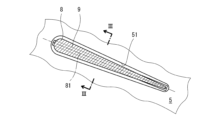
- FIG. 2 is a cross-sectional view of one vane
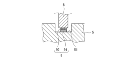
- FIG. 3 is a cross-sectional view taken along line III-III in FIG. 2.
- FIG. 1 shows a centrifugal turbomachine 1 according to one embodiment.
- the fluid used in the centrifugal turbomachine 1 may be either a gas or a liquid.
- the centrifugal turbomachine 1 is a single-stage type, but the centrifugal turbomachine 1 may also be a multi-stage type.
- the centrifugal turbomachine 1 includes an impeller 3, a hub 5 disposed on the rear side of the impeller 3, and a shroud 6 positioned around the impeller 3 and forming a radial flow passage 11 between the impeller 3 and the hub 5.
- the centrifugal turbomachine 1 includes a volute casing 7 forming a volute chamber communicating with the radial flow passage 11, but the volute chamber may be omitted.
- the impeller 3 includes a hub 31 that expands in diameter from the front to the back, and a number of blades 32 provided on the outer circumferential surface of the hub 31.
- the impeller 3 is fixed to the rotating shaft 2, and a bearing 4 that rotatably supports the rotating shaft 2 is held by the hub 5.
- vanes 8 are arranged in the radial flow passage 11.
- the vanes 8 are diffuser vanes when the centrifugal turbomachine 1 is a centrifugal compressor and a centrifugal pump, and are nozzle vanes when the centrifugal turbomachine 1 is a radial turbine.
- the vanes 8 are integrally provided with the shroud 6.
- the hub 5 is also formed with a number of recesses 51 into which the tips of the vanes 8 fit. Furthermore, a seal 9 is disposed within each recess 51 to provide a seal between the bottom of the recess 51 and the tip of the corresponding vane 8.
- the contour of the recess 51 is slightly larger than the contour of the vane 8.
- the vane 8 has a shape that widens from one end on the impeller 3 side to the other end opposite the impeller 3.
- the seal 9 has a constant width and is disposed along the center line 81 of the corresponding vane 8.
- the center line 81 is a straight line, but the center line 81 may also be a curved line.
- the seal 9 deforms in response to dimensional changes between the bottom of the recess 51 and the corresponding tip of the vane 8.
- the seal 9 is a brush seal including a base 91 and brush bristle material 92 embedded in the base 91, as shown in FIG. 3.
- the base 91 is fixed to the bottom of the recess 51 with an adhesive or the like, and the brush bristle material 92 is pressed against the tip surface of the vane 8 in an elastically deformed state.
- the brush bristle material 92 may be a metal wire or carbon fiber.
- the seal 9 may be a gap seal made of elastically deformable resin, in other words a strip made of resin.
- the resin may be nylon.
- the seals 9 arranged in each recess 51 deform in response to the dimensional change between the bottom of the recess 51 and the tip of the vane 8, so that when thermal deformation occurs in the hub 5 and shroud 6, a gap is prevented from being formed between the hub 5 and the vane 8 where the vane 8 is not provided. Therefore, the performance improvement effect of the centrifugal turbomachine 1 can be achieved regardless of the operating state, such as the design rated point or partial load.
- the vane 8 may be integrally provided on the hub 5, and a recess 51 may be formed in the shroud 6.
- a recess 51 may be formed in the shroud 6.
- the seals arranged in each recess deform in response to dimensional changes between the bottom of the recess and the tip of the vane, preventing the formation of gaps between the vanes and the hub or shroud on which the vanes are not provided when thermal deformation occurs in the hub and shroud.
- the seal may be positioned along the centerline of the corresponding vane.
- the seal may be a brush seal or an elastically deformable resin gap seal.
Landscapes
- Engineering & Computer Science (AREA)
- Mechanical Engineering (AREA)
- General Engineering & Computer Science (AREA)
- Structures Of Non-Positive Displacement Pumps (AREA)
Abstract
遠心式ターボ機械(1)は、羽根車(3)と、羽根車(3)の背面側に配置されるハブ(5)と、羽根車(3)の周囲に位置し、ハブ(5)との間に径方向流路(11)を形成するシュラウド(6)を含む。ハブ(5)とシュラウド(6)の一方には、径方向流路(11)内に配置される複数のベーン(8)が設けられ、ハブ(5)とシュラウド(6)の他方には、ベーン(8)の先端がそれぞれ嵌まり込む複数の窪み(51)が形成されている。各窪み(51)内には、当該窪み(51)の底と対応するベーン(8)の先端との間をシールする、窪み(51)の底とベーン(8)の先端との間の寸法変化に追従して変形するシール(9)が配置されている。
Description
本開示は、遠心式ターボ機械に関する。
従来から、遠心圧縮機、遠心ポンプ、ラジアルタービンなどの遠心式ターボ機械が知られている。遠心圧縮機および遠心ポンプは流体に仕事を与えて昇圧し、ラジアルタービンは高圧の流体から動力を回収する。
遠心式ターボ機械は、羽根車と、前記羽根車の背面側に配置されるハブと、前記羽根車の周囲に位置し、前記ハブとの間に径方向流路を形成するシュラウドを含む。ハブまたはシュラウドには、前記径方向流路内に配置される複数のベーンが設けられる。ベーンは、例えば、遠心圧縮機および遠心ポンプではディフューザーベーンであり、ラジアルタービンではノズルベーンである。
一般的に、ハブとシュラウドのうちのベーンが設けられていない方とベーンとの間には、熱変形によるそれらの接触を防止するためにある程度の隙間が形成される。しかし、前記隙間は、ターボ機械の性能を劣化させる漏洩流れを生じさせる。
例えば、特許文献1には、ハブとシュラウドのうちのベーンが設けられていない方に、ベーンの先端が嵌まり込む窪みが形成された遠心圧縮機が開示されている。なお、窪みは、特許文献1では「凹部」と呼ばれている。このような遠心圧縮機では、ハブとシュラウドのうちのベーンが設けられていない方とベーンとの間の隙間を通じた漏洩流れが低減される。
特許文献1の遠心圧縮機の構造を、ある程度の高温や低温で運転するターボ機械に対して適用する場合、上述した窪みが、設計定格点辺りでベーンの先端と当該窪みの間のクリアランスが最小となるようなサイズに設定される。一方、ターボ機械は、設計定格点よりも低い回転数や低い圧力比といった条件下での部分負荷で運転されることも多い。しかし、このような部分負荷では、設計定格点に対して熱バランスや温度分布が大きく変わるため、ベーンの先端と窪みの間のクリアランスが増大する。このため、漏洩流れの低減による性能向上効果が限定的である。
そこで、本開示は、設計定格点や部分負荷といった運転状態に拘わらずに性能向上効果を発揮できる遠心式ターボ機械を提供することを目的とする。
本開示は、羽根車と、前記羽根車の背面側に配置されるハブと、前記羽根車の周囲に位置し、前記ハブとの間に径方向流路を形成するシュラウドと、前記ハブと前記シュラウドの一方に設けられた、前記径方向流路内に配置される複数のベーンと、を備え、前記ハブと前記シュラウドの他方には、前記複数のベーンの先端がそれぞれ嵌まり込む複数の窪みが形成されており、各窪み内には、当該窪みの底と対応するベーンの先端との間をシールする、前記窪みの底と前記ベーンの先端との間の寸法変化に追従して変形するシールが配置されている、遠心式ターボ機械を提供する。
本開示によれば、設計定格点や部分負荷といった運転状態に拘わらずに性能向上効果を発揮できる遠心式ターボ機械が提供される。
図1に、一実施形態に係る遠心式ターボ機械1を示す。遠心式ターボ機械1に用いられる流体は気体と液体のどちらであってもよい。本実施形態では遠心式ターボ機械1が単段式であるが、遠心式ターボ機械1は多段式であってもよい。
遠心式ターボ機械1は、羽根車3と、羽根車3の背面側に配置されるハブ5と、羽根車3の周囲に位置し、ハブ5との間に径方向流路11を形成するシュラウド6を含む。本実施形態では、遠心式ターボ機械1が径方向流路11と連通する渦巻室を形成する渦巻ケーシング7を含むが、渦巻室はなくてもよい。
羽根車3は、正面から背面に向かって拡径するハブ31と、ハブ31の外周面に設けられた複数のブレード32を含む。羽根車3は回転軸2に固定されており、回転軸2を回転可能に支持するベアリング4がハブ5に保持されている。
径方向流路11には複数のベーン8が配置されている。ベーン8は、遠心式ターボ機械1が遠心圧縮機および遠心ポンプである場合はディフューザーベーンであり、遠心式ターボ機械1がラジアルタービンである場合はノズルベーンである。
本実施形態では、ベーン8がシュラウド6に一体的に設けられている。また、ハブ5には、ベーン8の先端がそれぞれ嵌まり込む複数の窪み51が形成されている。さらに、各窪み51内には、当該窪み51の底と対応するベーン8の先端との間をシールするシール9が配置されている。
図2に示すように、窪み51の輪郭はベーン8の輪郭よりも僅かに大きい。ベーン8は、羽根車3側の一端から羽根車3とは反対側の他端に向かって幅が広くなる形状を有する。一方、シール9は、一定の幅を有し、対応するベーン8の中心線81に沿って配置されている。図2では、中心線81が直線であるが、中心線81は曲線であってもよい。
シール9は、窪み51の底と対応するベーン8の先端との間の寸法変化に追従して変形するものである。本実施形態では、シール9が、図3に示すように、ベース91と、ベース91に植え込まれたブラシ毛材92を含むブラシシールである。ベース91が窪み51の底に接着剤などで固定されており、ブラシ毛材92が弾性変形した状態でベーン8の先端面に押し付けられている。例えば、ブラシ毛材92は、金属ワイヤであってもよいし、カーボンファイバーであってもよい。
ただし、シール9は、弾性変形可能な樹脂製の隙間シール、換言すれば樹脂からなる帯状体であってもよい。例えば、樹脂としてはナイロンなどが挙げられる。
以上説明したように、本実施形態の遠心式ターボ機械1では、各窪み51内に配置されたシール9が窪み51の底とベーン8の先端との間の寸法変化に追従して変形するので、ハブ5およびシュラウド6に熱変形が生じたときにベーン8が設けられていないハブ5とベーン8との間に隙間が形成されることが防止される。従って、設計定格点や部分負荷といった運転状態に拘わらずに遠心式ターボ機械1の性能向上効果を発揮することができる。
<変形例>
本開示は上述した実施形態に限定されるものではなく、本開示の要旨を逸脱しない範囲で種々の変形が可能である。
本開示は上述した実施形態に限定されるものではなく、本開示の要旨を逸脱しない範囲で種々の変形が可能である。
例えば、前記実施形態とは逆に、ベーン8がハブ5に一体的に設けられ、シュラウド6に窪み51が形成されてもよい。この構成であれば、ハブ5およびシュラウド6に熱変形が生じたときにベーン8が設けられていないシュラウド6とベーン8との間に隙間が形成されることが防止される。
<まとめ>
第1の態様として、本開示は、羽根車と、前記羽根車の背面側に配置されるハブと、前記羽根車の周囲に位置し、前記ハブとの間に径方向流路を形成するシュラウドと、前記ハブと前記シュラウドの一方に設けられた、前記径方向流路内に配置される複数のベーンと、を備え、前記ハブと前記シュラウドの他方には、前記複数のベーンの先端がそれぞれ嵌まり込む複数の窪みが形成されており、各窪み内には、当該窪みの底と対応するベーンの先端との間をシールする、前記窪みの底と前記ベーンの先端との間の寸法変化に追従して変形するシールが配置されている、遠心式ターボ機械を提供する。
第1の態様として、本開示は、羽根車と、前記羽根車の背面側に配置されるハブと、前記羽根車の周囲に位置し、前記ハブとの間に径方向流路を形成するシュラウドと、前記ハブと前記シュラウドの一方に設けられた、前記径方向流路内に配置される複数のベーンと、を備え、前記ハブと前記シュラウドの他方には、前記複数のベーンの先端がそれぞれ嵌まり込む複数の窪みが形成されており、各窪み内には、当該窪みの底と対応するベーンの先端との間をシールする、前記窪みの底と前記ベーンの先端との間の寸法変化に追従して変形するシールが配置されている、遠心式ターボ機械を提供する。
上記の構成によれば、各窪み内に配置されたシールが窪みの底とベーンの先端との間の寸法変化に追従して変形するので、ハブおよびシュラウドに熱変形が生じたときにハブとシュラウドのうちのベーンが設けられていない方とベーンとの間に隙間が形成されることが防止される。従って、設計定格点や部分負荷といった運転状態に拘わらずに遠心式ターボ機械の性能向上効果を発揮することができる。
第2の態様として、第1の態様において、例えば、前記シールは、対応するベーンの中心線に沿って配置されてもよい。
第3の態様として、第1または第2の態様において、例えば、前記シールは、ブラシシールまたは弾性変形可能な樹脂製の隙間シールであってもよい。
Claims (3)
- 羽根車と、
前記羽根車の背面側に配置されるハブと、
前記羽根車の周囲に位置し、前記ハブとの間に径方向流路を形成するシュラウドと、
前記ハブと前記シュラウドの一方に設けられた、前記径方向流路内に配置される複数のベーンと、を備え、
前記ハブと前記シュラウドの他方には、前記複数のベーンの先端がそれぞれ嵌まり込む複数の窪みが形成されており、
各窪み内には、当該窪みの底と対応するベーンの先端との間をシールする、前記窪みの底と前記ベーンの先端との間の寸法変化に追従して変形するシールが配置されている、遠心式ターボ機械。 - 前記シールは、対応するベーンの中心線に沿って配置されている、請求項1に記載の遠心式ターボ機械。
- 前記シールは、ブラシシールまたは弾性変形可能な樹脂製の隙間シールである、請求項1または2に記載の遠心式ターボ機械。
Applications Claiming Priority (2)
| Application Number | Priority Date | Filing Date | Title |
|---|---|---|---|
| JP2023191343A JP2025078978A (ja) | 2023-11-09 | 2023-11-09 | 遠心式ターボ機械 |
| JP2023-191343 | 2023-11-09 |
Publications (1)
| Publication Number | Publication Date |
|---|---|
| WO2025100012A1 true WO2025100012A1 (ja) | 2025-05-15 |
Family
ID=95695168
Family Applications (1)
| Application Number | Title | Priority Date | Filing Date |
|---|---|---|---|
| PCT/JP2024/027693 Pending WO2025100012A1 (ja) | 2023-11-09 | 2024-08-02 | 遠心式ターボ機械 |
Country Status (2)
| Country | Link |
|---|---|
| JP (1) | JP2025078978A (ja) |
| WO (1) | WO2025100012A1 (ja) |
Citations (2)
| Publication number | Priority date | Publication date | Assignee | Title |
|---|---|---|---|---|
| JPS5082708U (ja) * | 1973-12-03 | 1975-07-16 | ||
| JP2010196705A (ja) * | 2009-02-24 | 2010-09-09 | Dyson Technology Ltd | 遠心圧縮機 |
-
2023
- 2023-11-09 JP JP2023191343A patent/JP2025078978A/ja active Pending
-
2024
- 2024-08-02 WO PCT/JP2024/027693 patent/WO2025100012A1/ja active Pending
Patent Citations (2)
| Publication number | Priority date | Publication date | Assignee | Title |
|---|---|---|---|---|
| JPS5082708U (ja) * | 1973-12-03 | 1975-07-16 | ||
| JP2010196705A (ja) * | 2009-02-24 | 2010-09-09 | Dyson Technology Ltd | 遠心圧縮機 |
Also Published As
| Publication number | Publication date |
|---|---|
| JP2025078978A (ja) | 2025-05-21 |
Similar Documents
| Publication | Publication Date | Title |
|---|---|---|
| US11098731B2 (en) | Grooved shroud casing treatment for high pressure compressor in a turbine engine | |
| US7614847B2 (en) | Pattern for the surface of a turbine shroud | |
| EP1967699B1 (en) | Gas turbine engine with an abradable seal | |
| US7600968B2 (en) | Pattern for the surface of a turbine shroud | |
| US20120230818A1 (en) | Airfoil and corresponding guide vane, blade, gas turbine and turbomachine | |
| US20130149118A1 (en) | Labyrinth seals | |
| JP5630576B2 (ja) | ガスタービン | |
| EP2309097A1 (en) | Airfoil and corresponding guide vane, blade, gas turbine and turbomachine | |
| US20100196139A1 (en) | Leakage flow minimization system for a turbine engine | |
| JP2012233475A (ja) | ステータベーン列を備えた遠心圧縮機組立体 | |
| CN110206592B (zh) | 用于径流式叶轮机械的耐高温高压一体式叶轮-密封结构 | |
| JP2011528081A (ja) | 低ギャップ損失を有する軸流ターボ機械 | |
| US8561997B2 (en) | Adverse pressure gradient seal mechanism | |
| US4645417A (en) | Compressor casing recess | |
| JP2018009569A (ja) | ガスタービン圧縮機受動間隙制御 | |
| JP2011137458A (ja) | タービンエンジンにおける圧縮機の動作に関するシステム及び装置 | |
| EP2971547A1 (en) | Cantilever stator with vortex initiation feature | |
| US5653579A (en) | Ceramic blade with tip seal | |
| JP2016160938A (ja) | 翼形部及び翼形部の先端における圧力を管理する方法 | |
| CA1300030C (en) | Vane assembly for a gas turbine | |
| US9470101B2 (en) | Turbomachine | |
| JP2025078978A (ja) | 遠心式ターボ機械 | |
| CN119755134A (zh) | 一种低振动叶片结构及应用其的离心或透平流体机械 | |
| JP2019002361A (ja) | ターボ機械 | |
| US20190162074A1 (en) | Rotatable component for turbomachines, including a non-axisymmetric overhanging portion |
Legal Events
| Date | Code | Title | Description |
|---|---|---|---|
| 121 | Ep: the epo has been informed by wipo that ep was designated in this application |
Ref document number: 24888314 Country of ref document: EP Kind code of ref document: A1 |
|
| NENP | Non-entry into the national phase |
Ref country code: DE |