WO2025089280A1 - ケージ異常検出装置、及びケージ異常検出方法 - Google Patents
ケージ異常検出装置、及びケージ異常検出方法 Download PDFInfo
- Publication number
- WO2025089280A1 WO2025089280A1 PCT/JP2024/037614 JP2024037614W WO2025089280A1 WO 2025089280 A1 WO2025089280 A1 WO 2025089280A1 JP 2024037614 W JP2024037614 W JP 2024037614W WO 2025089280 A1 WO2025089280 A1 WO 2025089280A1
- Authority
- WO
- WIPO (PCT)
- Prior art keywords
- cage
- egg
- abnormality detection
- eggs
- row
- Prior art date
- Legal status (The legal status is an assumption and is not a legal conclusion. Google has not performed a legal analysis and makes no representation as to the accuracy of the status listed.)
- Pending
Links
Images


Classifications
-
- A—HUMAN NECESSITIES
- A01—AGRICULTURE; FORESTRY; ANIMAL HUSBANDRY; HUNTING; TRAPPING; FISHING
- A01K—ANIMAL HUSBANDRY; AVICULTURE; APICULTURE; PISCICULTURE; FISHING; REARING OR BREEDING ANIMALS, NOT OTHERWISE PROVIDED FOR; NEW BREEDS OF ANIMALS
- A01K45/00—Other aviculture appliances, e.g. devices for determining whether a bird is about to lay
-
- A—HUMAN NECESSITIES
- A01—AGRICULTURE; FORESTRY; ANIMAL HUSBANDRY; HUNTING; TRAPPING; FISHING
- A01K—ANIMAL HUSBANDRY; AVICULTURE; APICULTURE; PISCICULTURE; FISHING; REARING OR BREEDING ANIMALS, NOT OTHERWISE PROVIDED FOR; NEW BREEDS OF ANIMALS
- A01K29/00—Other apparatus for animal husbandry
-
- A—HUMAN NECESSITIES
- A01—AGRICULTURE; FORESTRY; ANIMAL HUSBANDRY; HUNTING; TRAPPING; FISHING
- A01K—ANIMAL HUSBANDRY; AVICULTURE; APICULTURE; PISCICULTURE; FISHING; REARING OR BREEDING ANIMALS, NOT OTHERWISE PROVIDED FOR; NEW BREEDS OF ANIMALS
- A01K31/00—Housing birds
- A01K31/14—Nest-boxes, e.g. for singing birds or the like
- A01K31/16—Laying nests for poultry; Egg collecting
-
- A—HUMAN NECESSITIES
- A01—AGRICULTURE; FORESTRY; ANIMAL HUSBANDRY; HUNTING; TRAPPING; FISHING
- A01K—ANIMAL HUSBANDRY; AVICULTURE; APICULTURE; PISCICULTURE; FISHING; REARING OR BREEDING ANIMALS, NOT OTHERWISE PROVIDED FOR; NEW BREEDS OF ANIMALS
- A01K43/00—Testing, sorting or cleaning eggs ; Conveying devices ; Pick-up devices
Definitions
- the present invention relates to a cage abnormality detection device and a cage abnormality detection method.
- Patent Document 1 Conventionally, it has been considered to manage the number of eggs laid by laying hens for each individual cage in an egg-laying hen house.
- the number of eggs laid is managed for a single row of cages.
- Patent Document 1 it is possible to evaluate the number of eggs laid in a row of cages from past data, to identify a cage row that lays fewer eggs than the standard number of eggs laid in a day, and to analyze egg-laying trends in a cage row over the past week.
- Patent Document 1 it is difficult to quickly and easily detect abnormalities in a specific cage row or cage by simply managing the egg production rate for a single cage row.
- the present invention aims to quickly and easily detect abnormalities in a specific cage row or cage by relatively comparing multiple cage rows.
- the cage abnormality detection device of the present invention is characterized by having sensors corresponding to multiple cage rows housing egg-laying hens of approximately the same age, and an abnormality detection unit that detects abnormalities in a specific cage or cage row based on information obtained from the sensors.
- This cage abnormality detection device detects abnormalities in a specific cage or cage row contained in multiple cage rows by relatively comparing the multiple cage rows based on information obtained from sensors corresponding to the multiple cage rows housing egg-laying hens of approximately the same age, making it possible to quickly and easily detect abnormalities such as egg-laying abnormalities, egg-collection abnormalities, equipment abnormalities, and egg-laying hens.
- abnormalities such as egg-laying abnormalities, egg-collection abnormalities, equipment abnormalities, and egg-laying hens can be quickly and easily detected, making it possible to quickly and easily detect, for example, malfunctions of feeders or water dispensers, the outbreak of infectious diseases, the influence of microorganisms such as mites, or a decrease in egg laying due to ventilation conditions, etc.
- the abnormality can be detected by detecting eggs on the egg collection belt that is installed along the cage row. For this reason, it is desirable that the sensor is fixed to the egg collection belt installed in each of the multiple cage rows, or is installed so as to be movable along the egg collection belt. If the sensor moves along the egg collection belt, the sensor may be configured to detect the condition of the egg-laying hens in the cage.
- one example of installing a sensor so as to be movable along the egg collection belt is to install it on a traveling cart that has a feeder, etc.
- the senor it is desirable for the sensor to detect the eggs placed on the egg collection belt or their physical properties.
- the abnormality detection unit In order to detect abnormalities by simply comparing the information of multiple cage rows, it is desirable for the abnormality detection unit to treat the cage row equipped with the egg collection belt that starts and stops at the same timing as a comparison group, and detect abnormalities in a specific cage or cage row included in the comparison group. This allows for comparison of information from multiple egg collection belts (multiple cage rows considered as a comparison group) that have the same egg collection time and number of egg collections, making it possible to accurately detect abnormalities such as egg-laying abnormalities.
- the cage abnormality detection device of the present invention prefferably includes a recording unit that links the information obtained from the sensor to position information within the cage row and records the information.
- the abnormality detection unit When detecting an abnormality in a specific cage row among multiple cage rows, depending on the condition of each cage row, it may not be possible to accurately detect the abnormality just by comparing the information obtained from the sensor. For example, if half of the laying hens in the third cage row died last week due to a breakdown in the drinking water faucet, an abnormality in the specific cage row will be erroneously detected if the egg information from the egg collection belt corresponding to the third cage row is used as is. Therefore, it is desirable for the abnormality detection unit to detect an abnormality in the specific cage or cage row based on cage row information including information on the laying hens housed in each cage in each of the multiple cage rows, in addition to the information obtained from the sensor.
- the abnormality detection unit When detecting an abnormality in a specific cage row among multiple cage rows, depending on the health of the egg-laying hens housed in each cage row, it may not be possible to accurately detect the abnormality by simply comparing the information obtained from the sensors. Therefore, it is desirable for the abnormality detection unit to detect an abnormality in the specific cage or cage row using egg-laying hens information including the body temperature or activity level of the egg-laying hens in addition to the information obtained from the sensors.
- the cage abnormality detection device of the present invention includes a collection belt that collects eggs from the multiple cage rows by cage row, the sensor is a camera that captures images of the eggs on the collection belt, and the abnormality detection unit detects abnormalities in the specific cage or cage row based on the image captured by the camera.
- the cage abnormality detection method is characterized in that sensors are provided in correspondence with multiple cage rows housing laying hens of approximately the same age, and an abnormality in a specific cage or cage row included in the multiple cage rows is detected based on information obtained from the sensors.
- the egg collection management system of the present invention is characterized by comprising an egg collection belt that collects eggs from a row of cages housing laying hens and transports them downstream, which is one end of the cage row, an egg stopper that moves between a blocking position that stops the movement of the eggs from the cage row to the egg collection belt and an open position that allows the movement of the eggs from the cage row to the egg collection belt, and a control device that coordinates and controls the operation of the egg collection belt and the egg stopper.
- the operation of the egg collection belt and the egg stopper are coordinated and controlled. For example, by setting the egg stopper to the blocking position while the egg collection belt is in transporting motion, new eggs will not be transferred in from each cage while the egg collection belt is in transporting motion, and egg-laying information such as the number of eggs laid in each cage before the egg collection belt starts to be transported, and the presence or absence of dirty eggs or deformed eggs, can be accurately managed.
- abnormalities such as egg-laying abnormalities, egg-collection abnormalities, equipment abnormalities, and egg-laying hen abnormalities can be accurately detected, so that, for example, a decrease in the number of eggs laid due to malfunctions of feeders or water dispensers, the outbreak of infectious diseases, the influence of microorganisms such as mites, or ventilation conditions, etc. can be accurately detected.
- control device set the egg stopper to the blocking position during a circular transport operation in which the egg collection belt transports the eggs released from the most upstream cage downstream.
- the control device If the egg stopper is in the blocking position before starting the circular conveying operation, it is desirable for the control device to set the egg stopper to the open position, then to the blocking position, and then to start the circular conveying operation.
- the eggs remaining in each cage can be moved to the egg collection belt before the egg collection belt starts its circular transport operation.
- egg-laying information such as the number of eggs laid in each cage and the presence or absence of dirty eggs or deformed eggs before the egg collection belt starts its circular transport operation can be managed with high accuracy.
- the egg management system of the present invention desirably comprises an egg sensor provided at one end of the cage row for detecting the eggs or physical properties of the eggs transported by the egg collection belt, and a recording unit for recording information obtained from the egg sensor by linking it to cage information such as cage numbers.
- the control device performs a temporary release operation to temporarily set the egg stopper to the open position during the conveying operation of the egg collection belt.
- the recording unit records conveying distance information from the start of the round conveying operation of the egg collection belt to the temporary release operation.
- control device coordinates and controls the operation of the egg collection belt and the operation of the egg stopper based on time-zone-specific egg-laying information according to the physiology of the egg-laying hens.
- the egg collection belt can be transported during times that avoid peak egg-laying hens' egg-laying peak hours.
- the egg-laying information acquisition method of the present invention is a method for acquiring egg-laying information in an egg-laying hen house having an egg collection belt that collects eggs from a row of cages housing egg-laying hens and transports them downstream, which is one end of the cage row, and an egg stopper that moves between a blocking position that stops the movement of the eggs from the cage row to the egg collection belt and an open position that allows the movement of the eggs from the cage row to the egg collection belt, wherein, with the egg stopper in the blocking position, an egg sensor that detects the eggs or physical properties of the eggs is moved along the egg collection belt, or the egg sensor is fixed to one end of the cage row and the eggs are transported by the egg collection belt, thereby acquiring egg-laying information corresponding to each cage.
- egg-laying information corresponding to each cage is acquired with the egg stopper in the blocking position. Therefore, new eggs are not transferred in from each cage when the egg sensor detects them, and egg-laying information such as the number of eggs laid in each cage and the presence or absence of dirty eggs or deformed eggs can be acquired with high accuracy.
- the present invention configured in this way, allows for relative comparison of multiple cage rows, making it possible to quickly and easily detect abnormalities in a specific cage row or cage.
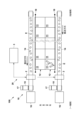
- FIG. 1 is a plan view showing a schematic diagram of an egg-laying chicken house system according to one embodiment of the present invention.
- FIG. 2 is a side view showing a schematic diagram of the egg-laying chicken house system of the embodiment.
- FIG. 2 is a functional block diagram of the cage abnormality detection device of the embodiment.
- 5 is a schematic diagram showing the relationship between the round transport operation of the egg collection belt and the opening and closing operation of the egg stopper in the embodiment.
- FIG. FIG. 11 is a diagram showing the number distribution in each cage before the egg collection belt starts its circular transport operation in this embodiment.
- FIG. 4 is a diagram showing detection information etc. according to the embodiment.
- 13 is a schematic diagram showing an egg collecting operation and detected eggs when a temporary release operation is performed in the modified embodiment.
- FIG. 13A and 13B are a side view and a plan view, respectively, illustrating a cage abnormality detection device according to a modified embodiment.
- the egg-laying hen house system 100 of this embodiment has an egg-laying hen house 10 having an artificial environment adjustment function such as an enclosed chicken house (windowless chicken house) for egg-laying hens, and a cage abnormality detection device 20 provided in the egg-laying hen house 10.
- an artificial environment adjustment function such as an enclosed chicken house (windowless chicken house) for egg-laying hens
- a cage abnormality detection device 20 provided in the egg-laying hen house 10.
- the egg-laying hen house 10 is provided with a plurality of cage rows 12 in which a plurality of cages 11 housing egg-laying hens of approximately the same age are arranged in one direction.
- the cage rows 12 are arranged side by side from left to right as shown in Figures 1 and 2.
- the cage rows 12 are arranged in three tiers, one above the other, but the number of tiers is not limited to this.
- the egg-laying hens of approximately the same age include egg-laying hens whose ages differ by up to one month, and preferably include egg-laying hens whose ages differ by up to about two weeks.
- the egg-laying hen house 10 is also provided with a number of egg collection belts 14 that collect eggs E from each of the cage rows 12 and transport them to one end of the cage rows 12.
- one egg collection belt 14 is provided corresponding to each cage row 12.
- Each egg collection belt 14 is driven by a belt drive device 15 and moves toward one end of each cage row 12.
- the belt drive device can drive the multiple egg collection belts 14 collectively and can be configured using a belt drive motor or the like.
- the egg collection belts 14 and the belt drive device 15 form an egg collection conveyor.
- the eggs E transported to one end of each cage row 12 are then transported to another egg collection device 16.
- the belt drive device 15 is also provided with an encoder 17 for detecting the transport distance (movement distance) of the egg collection belt 14.
- the belt drive device 15 is controlled by the function of the control and calculation device 3, which will be described later.
- an egg stopper 18 is provided between each cage row 12 and each egg collection belt 14.
- This egg stopper 18 is moved by an actuator (not shown) between a blocking position that stops the movement from the cage row 12 to the egg collection belt 14 and an open position that allows the movement from the cage row 12 to the egg collection belt 14.
- the egg stopper 18 is controlled by the function of the control and calculation device 3, which will be described later.
- Cage abnormality detection device 20 detects abnormalities in a specific cage 11 or cage row 12 by detecting eggs E on each egg collection belt 14.
- This cage abnormality detection device 20 can detect abnormalities such as egg-laying abnormalities, egg-collection abnormalities, equipment abnormalities, egg-laying hen abnormalities, etc.
- detecting abnormalities in a cage 11 or cage row 12 includes detecting abnormalities such as egg-laying abnormalities, egg-collection abnormalities, equipment abnormalities, egg-laying hen abnormalities, etc.
- the cage abnormality detection device 20 is provided at one end (downstream end) of the cage row 12 and includes an egg sensor 2 that detects eggs E transported to the one end (downstream end) by the egg collection belt 14, and a control and calculation device 3 that detects abnormalities in the cage row 12 based on the detection signal of the egg sensor 2, etc.
- the egg sensor 2 is provided at one end (downstream end) of the cage row 12 in a position where it can detect eggs E on the egg collection belt 14.
- the egg sensor 2 of this embodiment is provided at the downstream end of the egg collection belt 14, between the most downstream cage 11 of the cage row 12 and the belt drive device 15.
- the egg sensor 2 may be, for example, an imaging sensor such as a camera or a line sensor, an ultrasonic sensor, an optical sensor (for example, a transmission type or reflection type photoelectric sensor), a capacitance sensor, a mechanical switch (limit switch), or the like.
- the control and calculation device 3 controls various devices for detecting abnormalities in the cages 11 or the cage rows 12, and also controls the egg collection belts 14 and egg stoppers 18.
- the control and calculation device 3 is composed of a computer having a CPU, memory, an input/output interface, an AD converter, an input device, a display device, etc.
- the CPU and peripheral devices work together based on a predetermined program stored in the memory to perform each function of the control and calculation device 3.
- the control and calculation device 3 may be composed of a single computer or multiple computers.
- the control and calculation device 3 has a drive device control unit 31 that controls the belt drive device 15 of the egg collection belt 14, and a stopper control unit 32 that controls the stopper drive actuator (not shown) of the egg stopper 18.
- the control device 30 consisting of the drive device control unit 31 and the stopper control unit 32 coordinates and controls the operation of the egg collection belt 14 and the egg stopper 18.
- the egg collection belt 14, egg stopper 18, control device 30, etc. constitute an egg collection management system.
- the drive device control unit 31 controls the belt drive device 15 so that the multiple egg collection belts 14 are driven with the same start and stop operations.
- the drive device control unit 31 synchronously controls the belt drive devices 15 that drive each of the multiple egg collection belts 14, so that the conveying start times and conveying stop times of the multiple egg collection belts 14 are the same.
- the multiple egg collection belts 14 perform their conveying operations at the same timing. Note that the conveying start times and conveying stop times of the multiple egg collection belts 14 do not need to be completely the same, and they may be slightly different.
- one-stop conveying operation in which the egg collection belt 14 makes a full revolution, all of the eggs on the egg collection belt 14, including the egg E that came out of the most upstream cage 11, are transported to one end (downstream end) of the cage row 12 and transferred to another egg collection device 16.
- the egg sensor 2 detects all of the eggs E on the egg collection belt 14.
- the stopper control unit 32 sets the egg stoppers 18 in the blocking position while the drive device control unit 31 is driving the egg collection belts 14 (during the conveying operation of the egg collection belts 14). Specifically, as shown in FIG. 4, the stopper control unit 32 sets the egg stoppers 18 in the blocking position during the one-loop conveying operation, and sets the egg stoppers 18 in the blocking position from the start of the one-loop conveying operation to the end of the one-loop conveying operation. This prevents new eggs E from moving from the cage row 12 to the egg collection belt 14 during the one-loop conveying operation of the egg collection belt 14.
- the one-loop conveying operation may end when the conveying distance information becomes the set distance, when the conveying time becomes the set time, or when the egg sensor 2 does not detect eggs E for a predetermined time. Then, when the one-loop conveying operation of the egg collection belt 14 ends, the stopper control unit 32 moves the egg stoppers 18 to the open position while the egg collection belt 14 is stopped. This allows new eggs E to move from the cage row 12 to the egg collection belt 14.
- the stopper control unit 32 sets the egg stopper 18 to the open position and then to the blocking position, and then starts the circular transport operation by the egg collection belt 14.
- the eggs E remaining in each cage 11 can be moved to the egg collection belt 14 before the egg collection belt 14 starts its circular transport operation.
- egg-laying information such as the number of eggs laid in each cage 11 before the egg collection belt 14 starts its circular transport operation, and the presence or absence of dirty eggs, deformed eggs, etc. can be accurately managed.
- the stopper control unit 32 controls the stopper drive actuator so that the multiple egg stoppers 18 are driven with the same blocking/opening operation.
- the stopper control unit 32 synchronously controls the stopper drive actuator that drives each of the multiple egg stoppers 18, so that the opening start time and opening stop time of the multiple egg stoppers 18 are the same.
- the multiple egg stoppers 18 perform the opening/blocking operation at the same timing. Note that the opening start time and opening stop time of the multiple egg stoppers 18 do not need to be completely the same, and may be slightly different.
- the control and calculation device 3 has an egg information calculation unit 33 that calculates egg information of the multiple egg collection belts 14 from the detection signals of each of the multiple egg sensors 2, and an abnormality detection unit 34 that detects an abnormality in a specific cage row 12 included in the multiple cage rows 12 based on the egg information of the multiple egg collection belts 14.
- the egg information calculation unit 33 detects and counts the eggs E based on the detection signal of the egg sensor 2.
- the egg information calculation unit 33 also obtains transport distance information using a pulse signal that is an output signal of the encoder 17 provided in the belt drive device 15, and each time an egg E is detected, the egg information calculation unit 33 can link the detection information (count information) of the egg E with the transport distance information (position information) at the time the egg E was detected and cage information such as the cage number, and record this as egg distribution information in the recording unit 35.
- the recording unit 35 can also record date and time information of the transport operation of the egg collection belt 14.
- a position display unit (not shown), such as a QR code, may be provided on the egg collection belt 14, and the position display unit may be read by the reading unit.
- FIG. 5 shows the number distribution when a round transport operation is performed in one cage row 12.
- This cage row is made up of 90 cages, with each cage housing eight laying hens (720 chickens in total).
- the horizontal axis (rows) represents the cage number
- the vertical axis (columns) represents the number of eggs.
- the number of eggs laid in cages 3 and 4 is significantly lower than in the other cages, and it can be seen that an abnormality has occurred in cages 3 and 4.
- the abnormality detection unit 34 detects abnormalities in a specific cage row 12 by comparing the egg information (here, the number information) of each of the multiple egg collection belts 14 obtained by the egg information calculation unit 33. In this embodiment, the abnormality detection unit 34 detects abnormalities in a specific cage row 12 by comparing egg information (here, the number information) under the same or similar conditions. Specifically, the abnormality detection unit 34 sets cage rows 12 equipped with egg collection belts 14 that start and stop at the same timing as a comparison group, and detects abnormalities in a specific cage 11 or cage row 12 included in the comparison group.
- the egg information (number information) of multiple egg collection belts 14 obtained during the same period is compared.
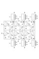
- Figure 6 shows egg information (number information) of egg collection belts corresponding to six cage rows a1-a3 and b1-b3, which are a comparison group, and by comparing them, an abnormality in specific cage row a2 is detected.
- a list of the egg information (including not only number information but also egg distribution information) shown in Figure 6 can be displayed on the display, and the specific cage row in which an abnormality was detected can also be displayed in a recognizable manner.
- possible methods for comparing egg information to detect abnormalities include detecting an abnormality when the egg information (number counted in one conveying operation) of multiple egg collection belts 14 deviates by more than a predetermined value from the average or median, or detecting an abnormality when the difference from the egg information of a predetermined egg collection belt 14 deviates by more than a predetermined value.
- the abnormality detection unit 34 may also detect abnormalities in a specific cage row 12 based on cage row information including information on the laying hens housed in each cage 11 in each of the cage rows 12, in addition to egg information on the multiple egg collection belts 14 (information obtained from the egg sensor 2). This cage row information is periodically updated with the latest chicken breed, age, number of individuals, etc.
- a machine learning algorithm may also be used to detect abnormalities by the abnormality detection unit 34. This machine learning algorithm may be supervised learning, in which various data accumulated in the recording unit 35 of the control calculation device 3, etc., is used as teacher data, or it may be unsupervised learning.
- the abnormality detection unit 34 may detect abnormalities in a specific cage row 12 based on egg-laying hen information including the body temperature or activity level of the egg-laying hens housed in each cage 11 in each of the cage rows 12, in addition to the egg information of the multiple egg collection belts 14 (information obtained from the egg sensor 2).
- this egg-laying hen information is measured periodically or in real time by a body temperature sensor such as a temperature sensor provided in each cage 11 or a specific cage 11, or a movement amount sensor such as a camera for measuring the movement amount of the egg-laying hens.
- control and calculation device 3 may have an abnormality notification unit 36 that notifies the occurrence of an abnormality when an abnormality is detected by the abnormality detection unit 34.
- This abnormality notification unit 36 may display information notifying the occurrence of an abnormality on a display device such as a display, or may use an indicator light or an alarm provided inside or outside the egg-laying hen house 10.
- abnormalities in a specific cage 11 or cage row 12 included in the cage rows 12 are detected by relatively comparing the cage rows 12 based on information obtained from the egg sensors 2 corresponding to each of the cage rows 12, so that abnormalities such as egg-laying abnormalities, egg-collection abnormalities, equipment abnormalities, and egg-laying hen abnormalities can be detected quickly and easily compared to the case where an abnormality in a cage row 12 is detected based on a single cage row 12.
- abnormalities such as egg-laying abnormalities, egg-collection abnormalities, equipment abnormalities, and egg-laying hen abnormalities can be detected quickly and easily, so that, for example, malfunctions of feeders or water dispensers, outbreaks of infectious diseases, influences of microorganisms such as mites, or a decrease in egg laying number due to ventilation conditions, etc. can be detected quickly and easily.
- the multiple egg collection belts 14 are driven with the same start/stop operation, and egg information from multiple egg collection belts 14 (multiple cage rows 12 considered as a comparison group) that have the same egg collection time and number of egg collections is compared, making it possible to accurately detect abnormalities in a specific cage 11 or cage row 12.
- the multiple egg stoppers 18 are driven with the same shutoff/open operation, and egg information from multiple egg collection belts 14 that have the same time period during which eggs E move from the cage row 12 is compared, making it possible to accurately detect abnormalities in a specific cage 11 or cage row 12.
- the egg information calculation unit 33 is provided in a control and calculation device 3 that is provided separately from the egg sensor 2, but the egg information calculation unit 33 and the egg sensor 2 may be integrated into one unit.
- the egg information calculation unit 33 may also calculate the physical properties of the egg E (e.g., the volume, weight, external shape or appearance of the egg, etc.) as egg information by, for example, processing two-dimensional image data from the imaging sensor that is the egg sensor 2.
- the physical properties of the egg E e.g., the volume, weight, external shape or appearance of the egg, etc.
- the control and calculation device 3 may also obtain the amount of feed provided by the feeder and the amount of feed consumed, and the amount of water provided by the waterer and the amount of water consumed, and use this data together with the egg information to detect abnormalities in a particular cage 11 or cage row 12.
- control and calculation device 3 may acquire operation information of the air conditioning equipment of the egg-laying chicken coop 10, and detect abnormalities in a specific cage 11 or cage row 12 from the operation information together with the egg information.
- the stopper control unit 32 it is desirable for the stopper control unit 32 to perform a temporary release operation that temporarily sets the egg stopper 18 to the open position during the round-trip conveying operation of the egg collection belt 14. It is also desirable for the recording unit 35 to record conveying distance information from the start of the round-trip conveying operation of the egg collection belt 14 to the temporary release operation.
- Figure 7 shows the egg collection operation when a temporary release operation is performed during the egg collection belt 14's round transport operation, and the cage from which the detected eggs E were transferred to the egg collection belt 14.
- Figure 7 shows (a) the egg collection from the day before yesterday (collection of one day's worth of eggs), (b) yesterday's egg collection (collection of one day's worth of eggs), and (c) today's egg collection (collection of one day's worth of eggs), and the temporary release operation is performed in (a) and (b).
- egg collection belt 14 carries eggs "A" corresponding to cages 1 to 60. Then, a circular transport operation is started. When egg E corresponding to cage 30 is detected by egg sensor 2 (9:15), a temporary release operation is performed and eggs “B” corresponding to cages 1 to 30 are newly added to egg E corresponding to cages 31 to 60 on egg collection belt 14. Then, the circular transport operation is resumed and ends. When the circular transport operation ends, egg collection belt 14 carries eggs “D” corresponding to cages 31 to 60 (see FIG. 7B). The eggs “D” corresponding to cages 31 to 60 are located in front of cages 1 to 30 on the egg collection belt 14.
- the egg collection belt 14 is in a state in which the eggs “G” corresponding to the cages 21 to 60 are placed on it (see FIG. 7(c)).
- the eggs "G” corresponding to cages 21 to 60 are located in front of cages 1 to 40 on the egg collection belt 14.
- control device 30 may coordinate the operation of the egg collection belt 14 and the egg stopper 18 based on time-zone-specific egg-laying information according to the physiology of the egg-laying hens. For example, after the peak egg-laying time period of the egg-laying hens according to the time-zone-specific egg-laying information has passed, the egg collection belt 14 may start its circular transport operation while the egg stopper 18 is maintained in the blocking position. With this configuration, for example, the transport operation of the egg collection belt can be performed while avoiding the peak egg-laying time period of the egg-laying hens.
- the comparison group in the abnormality detection unit 34 in the above embodiment is a plurality of cage rows 12 provided with egg collection belts 14 that start and stop at the same timing, but the comparison group is not limited to this.
- the comparison group may be cages 11 or cage rows 12 at different height positions in the egg-laying hen house 10 (e.g., upper floors, middle floors, and lower floors, etc.), or cages 11 at different positions or areas in the longitudinal direction of the cage row 12 (e.g., upstream, central, and downstream, near the air inlet, central part of the hen house, and near the air outlet, etc.).
- multiple areas in the longitudinal direction of the cage row 12 may overlap each other.
- the comparison group may include cages 11 or cage rows 12 of different egg-laying hen house 10.
- the comparison group may also be a plurality of cage rows 12 provided with egg collection belts 14 that start and stop at timings that are shifted by a predetermined time.
- the senor 2 is provided at the downstream end of the egg collection belt 14, but it may be provided so as to be movable along the egg collection belt 14.
- the sensor 2 may be provided on a traveling cart (not shown) that moves along the cage row 12.
- the traveling cart is provided with a feeder (not shown) that feeds food into a feed trough (not shown) provided along the cage row 12.
- the sensor 2 is not limited to a configuration that detects eggs on the egg collection belt 14, but may be a configuration that captures an image of the inside of each cage 11 to detect the condition of the egg-laying hens.
- the position information may be obtained from the travel distance from the starting point, or may be obtained by providing a position display unit (not shown) such as a QR code on the cage 11 and reading the position display unit with a reading unit.
- the egg sensor 2 in the above embodiment detects eggs on the egg collection belt 14, it may have the configuration shown in FIG. 7.
- the egg-laying chicken house 10 shown in FIG. 8 is equipped with a collection belt 19 that collects eggs E from multiple cage rows 12 for each cage row 12.
- This collection belt 19 is connected to multiple egg collection belts 14 and collects eggs E from multiple egg collection belts 14.
- FIG. 8 shows a configuration in which eggs E from a total of four cage rows 12, two rows in front and back and two rows above and below, are collected.
- a connection belt 191 is provided between the collection belt 19 and the egg collection belt 14 as necessary.
- the collection belt 19 has transport areas R1 to R4 corresponding to each cage row 12.
- This sensor 2 can be a camera that can capture images of the eggs E (the transport regions R1 to R4 corresponding to each cage row 12) on the collecting belt 19 all at once.
- the abnormality detection unit 34 detects abnormalities in a specific cage 11 or cage row 12 based on the image captured by camera 2.
- the number of apparent sensors can be reduced by making the pixel areas of the image captured by camera 2 correspond to each cage row 12.
- the abnormality detection unit 34 in the above embodiment detects an abnormality in a specific cage 11 or cage row 12 by relatively comparing the multiple cage rows 12 included in the comparison group, but in cases where there are a small number of cage rows 12, in addition to this relative comparison, an abnormality in a specific cage 11 or cage row 12 may be detected by comparing with previously prepared reference information or past data.
- previously prepared reference information include the standard number of eggs laid.
- the control and calculation device 3 of the cage abnormality detection device 20 in the above embodiment may be integrated with the control device of the egg-laying hen house 10 to configure the egg-laying hen house 10 and the cage abnormality detection device 20 to be controlled collectively.
- the present invention allows for quick and easy detection of abnormalities in a particular cage row or cage by relatively comparing multiple cage rows.
Landscapes
- Life Sciences & Earth Sciences (AREA)
- Environmental Sciences (AREA)
- Animal Husbandry (AREA)
- Biodiversity & Conservation Biology (AREA)
- Birds (AREA)
- Zoology (AREA)
- Housing For Livestock And Birds (AREA)
Priority Applications (3)
| Application Number | Priority Date | Filing Date | Title |
|---|---|---|---|
| JP2024572504A JP7751341B2 (ja) | 2023-10-23 | 2024-10-22 | ケージ異常検出装置、及びケージ異常検出方法 |
| CN202480027923.8A CN121099907A (zh) | 2023-10-23 | 2024-10-22 | 笼子异常检测装置以及笼子异常检测方法 |
| KR1020257031214A KR20250150121A (ko) | 2023-10-23 | 2024-10-22 | 케이지 이상 검출 장치 및 케이지 이상 검출 방법 |
Applications Claiming Priority (4)
| Application Number | Priority Date | Filing Date | Title |
|---|---|---|---|
| JP2023-181616 | 2023-10-23 | ||
| JP2023181616 | 2023-10-23 | ||
| JP2024100507 | 2024-06-21 | ||
| JP2024-100507 | 2024-06-21 |
Publications (1)
| Publication Number | Publication Date |
|---|---|
| WO2025089280A1 true WO2025089280A1 (ja) | 2025-05-01 |
Family
ID=95515602
Family Applications (1)
| Application Number | Title | Priority Date | Filing Date |
|---|---|---|---|
| PCT/JP2024/037614 Pending WO2025089280A1 (ja) | 2023-10-23 | 2024-10-22 | ケージ異常検出装置、及びケージ異常検出方法 |
Country Status (4)
| Country | Link |
|---|---|
| JP (1) | JP7751341B2 (https=) |
| KR (1) | KR20250150121A (https=) |
| CN (1) | CN121099907A (https=) |
| WO (1) | WO2025089280A1 (https=) |
Citations (3)
| Publication number | Priority date | Publication date | Assignee | Title |
|---|---|---|---|---|
| JPS58141735A (ja) * | 1982-02-17 | 1983-08-23 | 三菱電機株式会社 | 鶏卵計数装置 |
| JPH06343366A (ja) * | 1993-06-11 | 1994-12-20 | Toyo Syst Kk | 家禽ケージシステムにおける集卵監視装置 |
| US20220217951A1 (en) * | 2020-01-19 | 2022-07-14 | Zhejiang University | Method and system for monitoring egg-laying performance of caged laying-hens at laying-hen positions |
Family Cites Families (5)
| Publication number | Priority date | Publication date | Assignee | Title |
|---|---|---|---|---|
| JPS58141734A (ja) | 1982-02-17 | 1983-08-23 | 三菱電機株式会社 | 鶏卵計数装置 |
| JPH0198562U (https=) * | 1987-12-17 | 1989-06-30 | ||
| JPH02260091A (ja) * | 1989-03-31 | 1990-10-22 | Niyuurii Kk | 鶏卵等の搬送物品の数量計測装置 |
| JP4482399B2 (ja) | 2004-08-16 | 2010-06-16 | 富士通株式会社 | 死亡率自動推定方法および死亡率自動推定装置 |
| WO2008114417A1 (ja) | 2007-03-20 | 2008-09-25 | Toyo System Co., Ltd. | 集卵障害を迅速に警告するシステム |
-
2024
- 2024-10-22 CN CN202480027923.8A patent/CN121099907A/zh active Pending
- 2024-10-22 WO PCT/JP2024/037614 patent/WO2025089280A1/ja active Pending
- 2024-10-22 KR KR1020257031214A patent/KR20250150121A/ko active Pending
- 2024-10-22 JP JP2024572504A patent/JP7751341B2/ja active Active
Patent Citations (3)
| Publication number | Priority date | Publication date | Assignee | Title |
|---|---|---|---|---|
| JPS58141735A (ja) * | 1982-02-17 | 1983-08-23 | 三菱電機株式会社 | 鶏卵計数装置 |
| JPH06343366A (ja) * | 1993-06-11 | 1994-12-20 | Toyo Syst Kk | 家禽ケージシステムにおける集卵監視装置 |
| US20220217951A1 (en) * | 2020-01-19 | 2022-07-14 | Zhejiang University | Method and system for monitoring egg-laying performance of caged laying-hens at laying-hen positions |
Also Published As
| Publication number | Publication date |
|---|---|
| JPWO2025089280A1 (https=) | 2025-05-01 |
| KR20250150121A (ko) | 2025-10-17 |
| CN121099907A (zh) | 2025-12-09 |
| JP7751341B2 (ja) | 2025-10-08 |
Similar Documents
| Publication | Publication Date | Title |
|---|---|---|
| JP2024054082A (ja) | 鶏卵分布測定装置、採卵鶏舎飼養管理システム及び鶏卵分布測定方法 | |
| EP2205065B1 (en) | Method and apparatus for monitoring the performance of automated egg removal | |
| Patel et al. | Role of artificial intelligence in livestock and poultry farming | |
| US8339587B2 (en) | Method for detecting a malfunctioning egg picker | |
| CN116649236A (zh) | 一种奶牛养殖饲喂监控管理系统 | |
| Ali et al. | Daytime occupancy of resources and flooring types by 4 laying hen strains in a commercial-style aviary | |
| JP7751341B2 (ja) | ケージ異常検出装置、及びケージ異常検出方法 | |
| DE102019110304A1 (de) | Vorrichtung, Bausatz und Verfahren zur berührungslosen Ermittlung der Körpertemperatur eines Nutztieres | |
| CN212344985U (zh) | 一种用于笼养蛋鸡区位产蛋性能监测的装置 | |
| JP2024054838A (ja) | 鶏卵分布測定装置、採卵鶏舎システム及び鶏卵分布測定方法 | |
| Sriharee et al. | Toward IoT and data analytics for the chicken welfare using RFID technology | |
| CN220966052U (zh) | 一种选育用禽蛋关联装置 | |
| CN118542262A (zh) | 一种家禽笼养定量喂料装置及方法 | |
| CN218213410U (zh) | 一种栖架笼鸡只层间运动轨迹采集装置以及栖架笼 | |
| JP7287675B2 (ja) | 情報取得及び分析機能付きの卵充填装置 | |
| JP2024175408A (ja) | ケージ列産卵監視装置 | |
| JP7813075B1 (ja) | 異常鶏発見支援装置 | |
| JP7763547B1 (ja) | 異常鶏情報管理システム | |
| CN116963595A (zh) | 猪饲养辅助装置、猪饲养辅助方法以及猪饲养辅助程序 | |
| WO2026028561A1 (ja) | 弱体鶏検出装置、及び、弱体鶏検出プログラム | |
| TW202315518A (zh) | 家禽健康監測系統及其方法 | |
| KR102846436B1 (ko) | 가금의 중량 및 이미지 분석을 통한 가금의 일령별 평균 중량 산출 시스템 | |
| Kristensen et al. | The intelligent pig barn | |
| CN211129379U (zh) | 一种笼养鸡自动测温呼叫设施 | |
| CN112841075A (zh) | 一种笼养鸡自动测温呼叫设施 |
Legal Events
| Date | Code | Title | Description |
|---|---|---|---|
| ENP | Entry into the national phase |
Ref document number: 2024572504 Country of ref document: JP Kind code of ref document: A |
|
| WWE | Wipo information: entry into national phase |
Ref document number: 2024572504 Country of ref document: JP |
|
| 121 | Ep: the epo has been informed by wipo that ep was designated in this application |
Ref document number: 24882391 Country of ref document: EP Kind code of ref document: A1 |
|
| ENP | Entry into the national phase |
Ref document number: 1020257031214 Country of ref document: KR Free format text: ST27 STATUS EVENT CODE: A-0-1-A10-A15-NAP-PA0105 (AS PROVIDED BY THE NATIONAL OFFICE) |
|
| WWP | Wipo information: published in national office |
Ref document number: 1020257031214 Country of ref document: KR |
|
| WWE | Wipo information: entry into national phase |
Ref document number: CN2024800279238 Country of ref document: CN |