WO2025089117A1 - 空気入りタイヤ及びその製造方法 - Google Patents
空気入りタイヤ及びその製造方法 Download PDFInfo
- Publication number
- WO2025089117A1 WO2025089117A1 PCT/JP2024/036471 JP2024036471W WO2025089117A1 WO 2025089117 A1 WO2025089117 A1 WO 2025089117A1 JP 2024036471 W JP2024036471 W JP 2024036471W WO 2025089117 A1 WO2025089117 A1 WO 2025089117A1
- Authority
- WO
- WIPO (PCT)
- Prior art keywords
- tire
- sealant
- layer
- pneumatic tire
- sealant layer
- Prior art date
- Legal status (The legal status is an assumption and is not a legal conclusion. Google has not performed a legal analysis and makes no representation as to the accuracy of the status listed.)
- Pending
Links
Images


Classifications
-
- B—PERFORMING OPERATIONS; TRANSPORTING
- B29—WORKING OF PLASTICS; WORKING OF SUBSTANCES IN A PLASTIC STATE IN GENERAL
- B29C—SHAPING OR JOINING OF PLASTICS; SHAPING OF MATERIAL IN A PLASTIC STATE, NOT OTHERWISE PROVIDED FOR; AFTER-TREATMENT OF THE SHAPED PRODUCTS, e.g. REPAIRING
- B29C33/00—Moulds or cores; Details thereof or accessories therefor
- B29C33/02—Moulds or cores; Details thereof or accessories therefor with incorporated heating or cooling means
-
- B—PERFORMING OPERATIONS; TRANSPORTING
- B29—WORKING OF PLASTICS; WORKING OF SUBSTANCES IN A PLASTIC STATE IN GENERAL
- B29D—PRODUCING PARTICULAR ARTICLES FROM PLASTICS OR FROM SUBSTANCES IN A PLASTIC STATE
- B29D30/00—Producing pneumatic or solid tyres or parts thereof
- B29D30/06—Pneumatic tyres or parts thereof (e.g. produced by casting, moulding, compression moulding, injection moulding, centrifugal casting)
-
- B—PERFORMING OPERATIONS; TRANSPORTING
- B60—VEHICLES IN GENERAL
- B60C—VEHICLE TYRES; TYRE INFLATION; TYRE CHANGING; CONNECTING VALVES TO INFLATABLE ELASTIC BODIES IN GENERAL; DEVICES OR ARRANGEMENTS RELATED TO TYRES
- B60C1/00—Tyres characterised by the chemical composition or the physical arrangement or mixture of the composition
-
- B—PERFORMING OPERATIONS; TRANSPORTING
- B60—VEHICLES IN GENERAL
- B60C—VEHICLE TYRES; TYRE INFLATION; TYRE CHANGING; CONNECTING VALVES TO INFLATABLE ELASTIC BODIES IN GENERAL; DEVICES OR ARRANGEMENTS RELATED TO TYRES
- B60C19/00—Tyre parts or constructions not otherwise provided for
- B60C19/12—Puncture preventing arrangements
-
- B—PERFORMING OPERATIONS; TRANSPORTING
- B60—VEHICLES IN GENERAL
- B60C—VEHICLE TYRES; TYRE INFLATION; TYRE CHANGING; CONNECTING VALVES TO INFLATABLE ELASTIC BODIES IN GENERAL; DEVICES OR ARRANGEMENTS RELATED TO TYRES
- B60C5/00—Inflatable pneumatic tyres or inner tubes
-
- C—CHEMISTRY; METALLURGY
- C09—DYES; PAINTS; POLISHES; NATURAL RESINS; ADHESIVES; COMPOSITIONS NOT OTHERWISE PROVIDED FOR; APPLICATIONS OF MATERIALS NOT OTHERWISE PROVIDED FOR
- C09K—MATERIALS FOR MISCELLANEOUS APPLICATIONS, NOT PROVIDED FOR ELSEWHERE
- C09K3/00—Materials not provided for elsewhere
- C09K3/10—Materials in mouldable or extrudable form for sealing or packing joints or covers
-
- C—CHEMISTRY; METALLURGY
- C09—DYES; PAINTS; POLISHES; NATURAL RESINS; ADHESIVES; COMPOSITIONS NOT OTHERWISE PROVIDED FOR; APPLICATIONS OF MATERIALS NOT OTHERWISE PROVIDED FOR
- C09K—MATERIALS FOR MISCELLANEOUS APPLICATIONS, NOT PROVIDED FOR ELSEWHERE
- C09K3/00—Materials not provided for elsewhere
- C09K3/12—Materials for stopping leaks, e.g. in radiators, in tanks
Definitions
- the present invention relates to a pneumatic tire with a sealant layer on the inner surface of the tire in the tread portion and a manufacturing method thereof, and more specifically to a pneumatic tire that enhances the adhesion between the inner surface of the tire and the sealant layer, thereby improving the durability of the tire, and a manufacturing method thereof.
- the object of the present invention is to provide a pneumatic tire and a manufacturing method thereof that enhances the adhesion between the inner surface of the tire and the sealant layer and improves the durability of the tire.
- the pneumatic tire of the present invention for achieving the above object is a pneumatic tire having a tread portion extending in the circumferential direction of the tire to form an annular shape, a pair of sidewall portions arranged on both sides of the tread portion, and a pair of bead portions arranged on the radially inward side of these sidewall portions, the tire has a release layer containing a silicone-based composition on the inner surface of the tire, a sealant layer is formed on the radially inward side of the release layer in the tread portion, the sealant of the sealant layer is made of a silicone-based composition, and the absolute value of the difference between the contact angle of water with respect to the release layer and the contact angle of water with respect to the sealant layer is 30° or less.
- the method for manufacturing a pneumatic tire of the present invention for achieving the above-mentioned object is a method for manufacturing the above-mentioned pneumatic tire, characterized in that after manufacturing the pneumatic tire excluding the sealant layer, a sealant made of a silicone-based composition is applied to the inner surface of the tire in the tread portion to form the sealant layer, and the temperature of the sealant applied to the inner surface of the tire is set to 70°C or lower.
- the inventor discovered that in order to increase the adhesion between the inner surface of a tire and a sealant layer, it is effective to use the contact angle of water as an index of compatibility between components and set the absolute value of the difference in the contact angles within a specific range, which led to the invention.
- the tire has a release layer containing a silicone-based composition on the inner surface, a sealant layer is formed on the tire radially inward side of the release layer in the tread portion, and the sealant in the sealant layer is composed of a silicone-based composition, so that both the release layer and the sealant layer contain a silicone-based composition, which contributes to improving compatibility. Furthermore, by setting the absolute value of the difference between the contact angle of water with the release layer and the contact angle of water with the sealant layer to a specific range (30° or less), compatibility can be made extremely good. This can increase the adhesion between the inner surface of the tire and the sealant layer, improving the durability of the tire.
- the thickness of the release layer is preferably in the range of 0.1 ⁇ m to 100.0 ⁇ m. This can effectively improve the durability of the tire.
- the glass transition temperature of the sealant is preferably in the range of -120°C to -40°C.
- the silicone composition that makes up the sealant is preferably a two-component curing silicone.
- Two-component curing silicone has low viscosity immediately after mixing the two components, making it possible to apply the material even at low temperatures.
- the distance L from the belt layer to the sealant layer is 10 mm or less at all points of the belt layer located at the innermost side in the tire radial direction. This makes it easier for the sealant to flow into the belt layer when a foreign object such as a nail penetrates the tread portion, ensuring good puncture sealing properties.
- a sound-absorbing material is installed along the tire circumferential direction on the radially inner side of the sealant layer.
- the sound-absorbing material can be installed on the sealant layer that is applied at a low temperature, so damage to the sound-absorbing material can be avoided and its sound-absorbing effect can be well maintained.
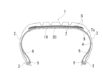
- FIG. 1 is a meridian cross-sectional view showing a pneumatic tire according to an embodiment of the present invention.
- FIG. 2 is a cross-sectional view showing a main part of the pneumatic tire of FIG. 3(a) and (b) are explanatory diagrams illustrating the contact angles ⁇ 10 and ⁇ 20 of water, respectively.
- FIG. 4 is a cross-sectional view showing an example of a method for manufacturing a pneumatic tire according to an embodiment of the present invention.
- FIG. 5 is a plan view showing a sealant layer formed on the inner surface of the tire in the tread portion of the pneumatic tire of FIG.
- FIG. 6 is a meridian cross-sectional view showing a pneumatic tire according to another embodiment of the present invention.
- Figures 1 and 2 show a pneumatic tire according to an embodiment of the present invention.
- the pneumatic tire of this embodiment has a tread portion 1 that extends in the circumferential direction of the tire to form an annular shape, a pair of sidewall portions 2 arranged on both sides of the tread portion 1, and a pair of bead portions 3 arranged radially inward of the sidewall portions 2.
- At least one carcass layer 4 (one layer in FIG. 1) is mounted between a pair of bead portions 3, and is made up of multiple carcass cords arranged in the radial direction.
- Organic fiber cords such as nylon and polyester are preferably used as the carcass cords that make up the carcass layer 4.
- An annular bead core 5 is embedded in each bead portion 3, and a bead filler 6 made of a rubber composition with a triangular cross section is arranged on the outer periphery of the bead core 5.
- the belt layer 7 includes multiple reinforcing cords that are inclined with respect to the tire circumferential direction, and are arranged so that the reinforcing cords cross each other between layers.
- the inclination angle of the reinforcing cords with respect to the tire circumferential direction is set in the range of 10° to 40°, for example.
- Steel cords are preferably used as the reinforcing cords of the belt layer 7.
- At least one belt cover layer 8 (two layers in FIG. 1) is arranged on the outer circumferential side of the belt layer 7, and is made of reinforcing cords arranged at an angle of, for example, 5° or less relative to the tire circumferential direction, with the aim of improving high-speed durability.
- This belt cover layer 8 is preferably a jointless structure in which a strip material made of at least one reinforcing cord that has been aligned and rubber-coated is continuously wound at an angle of substantially 0° relative to the tire circumferential direction.
- organic fiber cords such as nylon or aramid are preferably used.
- the above-mentioned tire internal structure shows a typical example of a pneumatic tire, but is not limited to this.
- An inner liner layer 9 is arranged along the carcass layer 4 as a component that constitutes the tire inner surface Ts.
- a release layer 10 is formed on the tire radially inner side of the tire inner surface Ts by applying or transferring a release agent.
- the release layer 10 contains a silicone-based composition.
- silicone-based compositions include synthetic polymer compounds having a main skeleton formed by siloxane bonds.
- the sealant layer 20 is formed continuously in the tire circumferential direction on the tire radial inner side of the release layer 10 in the tread portion 1. That is, the sealant layer 20, the release layer 10, and the tire inner surface Ts (inner liner layer 9) are laminated in this order from the tire radial inner side. It is preferable that the center position of the sealant layer 20 in the tire width direction coincides with the tire equator, but the center position may be shifted from the tire equator to either side in the tire width direction.
- the distance in the tire width direction between the center position of the sealant layer 20 in the tire width direction and the tire equator is preferably 10 mm or less, more preferably 5 mm or less.
- the sealant of the sealant layer 20 is composed of a silicone-based composition.
- the silicone-based composition includes a synthetic polymer compound having a main skeleton formed by a siloxane bond.
- the absolute value of the contact angle ⁇ 10 of water with respect to the release layer 10 and the absolute value of the contact angle ⁇ 20 of water with respect to the sealant layer 20 are preferably in the range of 90° to 120°.
- the absolute value of the contact angle ⁇ 10 of the release layer 10 and the absolute value of the contact angle ⁇ 20 of the sealant layer 20 are close to each other, and the absolute value of the difference between the contact angles ⁇ 10 and ⁇ 20 ,
- , is 30° or less.
- is preferably 20° or less, more preferably 10° or less.
- the contact angle of water is an index of compatibility, and adherends having similar contact angles tend to have high adhesion. Therefore, when the absolute value of the difference
- the contact angles ⁇ 10 and ⁇ 20 of water are measured in accordance with JIS R3257.
- a cut sample cut out from a product tire along the tire width direction can be used to measure the contact angles ⁇ 10 and ⁇ 20 of water on the release layer and sealant layer on the cut sample.
- the inner surface of the tire can be disassembled and processed into a sheet shape to perform the measurement.
- a sheet of sealant processed to a certain thickness before being applied to the inner surface of the tire, or a rubber sheet to which a release agent used for the inner surface of the tire is attached may also be used.
- FIG. 3 illustrates a case in which the contact angle ⁇ 20 is larger than the contact angle ⁇ 10 , but the magnitude relationship between the contact angles ⁇ 10 and ⁇ 20 is not limited to this.
- both the release layer 10 and the sealant layer 20 contain a silicone-based composition, which contributes to improving compatibility. Furthermore, the absolute value of the difference between the contact angle ⁇ 10 of water with the release layer 10 and the contact angle ⁇ 20 of water with the sealant layer 20,
- the glass transition temperature of the sealant in the sealant layer 20 is preferably in the range of -120°C to -40°C.
- the above-mentioned pneumatic tire can be manufactured by the following method.
- a pneumatic tire is manufactured that has the tread portion 1, a pair of sidewall portions 2, and a pair of bead portions 3 as described above, and has a release layer 10 containing a silicone-based composition formed on the tire inner surface Ts.
- the method of forming the release layer 10 on the tire inner surface Ts is not particularly limited, but for example, it can be formed by applying a release agent to the inner surface of a green tire during vulcanization.
- a sealant made of a silicone-based composition is applied to the tire inner surface Ts in the tread portion 1 to form a sealant layer 20.
- the temperature of the sealant applied to the tire inner surface Ts is set to 70°C or less. If this temperature exceeds 70°C, the distortion generated in the pneumatic tire during the process of applying the sealant to the tire inner surface Ts becomes large, and the durability of the tire deteriorates.
- the temperature of the sealant when applying the sealant to the tire inner surface Ts is preferably in the range of 5°C to 40°C, more preferably in the range of 10°C to 35°C, and most preferably in the range of 15°C to 30°C. This prevents over-vulcanization of the rubber member caused by heating during the formation of the sealant layer 20.
- the release layer 10 and the sealant layer 20 contain similar materials, they are easily compatible with each other, and the sealant layer 20 can be well adhered to the tire inner surface Ts.
- the sealant can be applied with the release agent attached to the tire inner surface, there is no need to perform a process of removing the release agent by buffing or laser treatment, which also leads to improved productivity.
- FIG. 4 shows a specific manufacturing method of a pneumatic tire according to an embodiment of the present invention
- FIG. 5 shows a sealant layer formed on the inner surface of the tire in the tread portion.
- the sealant extrusion device 31 mixes the sealants supplied from the pumps 32 and 33, and continuously discharges the mixed sealant from the nozzle 34 as a strip 21.
- the sealant extrusion device 31 is configured so that the position of the nozzle 34 can be freely changed.
- the sealant strip 21 can be arranged in a spiral shape on the release layer 10 while being inclined with respect to the tire circumferential direction Tc (see FIG. 5).
- the spirally arranged sealant strip 21 has its circumferential portions in close contact with each other.
- the sealant strip 21 arranged in a spiral shape is integrated to form the sealant layer 20.
- one-component curing silicone or two-component curing silicone can be used, but it is particularly preferable to use two-component curing silicone.
- One-component curing silicone can be, for example, moisture-curing silicone.
- Two-component curing silicone is composed of a first liquid and a second liquid, and a curing reaction begins by mixing these first and second liquids, and the stability of the sealant layer 20 is ensured after curing.
- the first and second liquids of the two-component curing silicone are supplied from pumps 32 and 33, respectively.
- Two-component curing silicone has a low viscosity immediately after mixing the two liquids, so it can be applied even at low temperatures.
- Two-component curing silicones are composed of, for example, a condensation curable silyl-terminated polymer, a silane crosslinker, a condensation catalyst, and a filler.
- condensation curable silyl-terminated polymers include polydialkylsiloxanes, alkylphenylsiloxanes, organic polymers having silyl groups (e.g., silyl polyethers, silyl acrylates), and polyisobutylenes having silyl groups.
- silane crosslinkers include alkoxy-functional silanes, oximosilanes, acetoxysilanes, and enoxysilanes.
- fillers include iron oxide, titanium dioxide, carbon black, and talc.
- condensation catalysts include titanates and zirconates. These condensation curable silyl-terminated polymers, silane crosslinkers, condensation catalysts, and fillers are stored in a state where they are separated into a first liquid and a second liquid in a combination that does not cause a curing reaction to proceed, and are mixed when used.
- two-component curing silicones include those described in Japanese Patent Publication No. 2018-503725 and Japanese Patent Publication No. 2022-550962.
- SST-2650 manufactured by Dow can be used as a commercially available two-component curing silicone.
- the belt cover layer 8 may cover only a portion of the belt layer 7 in the tire width direction (for example, the edge portions on both sides of the belt layer in the tire width direction), but it is preferable that the belt cover layer 8 covers the entire area of the belt layer 7 in the tire width direction. This can further improve the durability of the tire, and even if a nail is pierced, the amount of air leakage from the shoulder portion Sh can be suppressed, thereby further improving the puncture sealing performance.
- the belt cover layer 8 located on the inner side in the tire radial direction constitutes a full cover that covers the entire area of the belt layer 7, and the belt cover layer 8 located on the outer side in the tire radial direction constitutes an edge cover that covers only the edge portions of the belt layer 7.
- the thickness g of the release layer 10 is preferably in the range of 0.1 ⁇ m to 100.0 ⁇ m. In this way, by appropriately setting the thickness g of the release layer 10, the durability of the tire can be effectively improved.
- the thickness g of the release layer 10 is smaller than 0.1 ⁇ m, it will not blend well with the sealant layer 20, and the durability of the tire will deteriorate.
- it is larger than 100.0 ⁇ m the deformation of the release layer 10 will be significant when the tire deformation is applied to the release layer 10, accelerating the destruction of the release layer 10 and causing the sealant layer 20 to fall off.
- the thickness g of the release layer 10 is an average thickness.
- Such a thickness g of the release layer 10 can be detected using, for example, an electron microscope.
- an electron microscope When measuring the thickness g of the release layer 10 with an electron microscope, a cut sample cut from the tire along the tire width direction is used, and the thickness is measured at multiple locations on the cut sample (e.g., four locations in the tire circumferential direction and three locations in the tire width direction). The thickness g of the release layer 10 can be calculated by averaging the measurements at these multiple locations.
- the thickness S of the sealant layer 20 is preferably in the range of 2.0 mm to 5.0 mm. This ensures sufficient puncture sealing in the center as well as in the shoulders Sh. If the thickness S of the sealant layer 20 is less than 2.0 mm, the puncture sealing performance is reduced, and if it is greater than 5.0 mm, the sealant layer 20 will flow due to the centrifugal force of the tire, causing the tire to lose balance during running.
- the thickness S of the sealant layer 20 is the overall average thickness.
- the average thickness of the sealant layer 20 can be calculated, for example, by taking a tire meridian cross section at eight points around the tire circumference using a CT scan, and measuring the thickness of the sealant layer 20 at five points in each image taken: the tire equator, the outer edge positions (both sides) 10 mm inward in the tire width direction from the end 20e of the sealant layer 20, and the intermediate positions (both sides) between the tire equator and the outer edge positions.
- the distance (shortest distance) L from the belt layer 7 to the sealant layer 20 is 10 mm or less at all points of the belt layer 7 located at the innermost side in the tire radial direction. This makes it easier for the sealant to flow into the belt layer 7 when a foreign object such as a nail penetrates the tread portion 1, thereby ensuring good puncture sealing properties. If there is a part where the distance L from the belt layer 7 to the sealant layer 20 is greater than 10 mm, there is a risk that the puncture sealing properties in that part will be insufficient.
- FIG. 6 shows a pneumatic tire according to another embodiment of the present invention.
- a sound-absorbing material 40 is installed along the tire circumferential direction on the tire radially inner side of the sealant layer 20.
- the sound-absorbing material 40 is made of a porous material having open cells, and has a predetermined sound-absorbing characteristic based on its porous structure. It is preferable to use foamed polyurethane as the porous material of the sound-absorbing material 40.
- the sound-absorbing material 40 is attached onto the sealant layer 20 based on the adhesiveness of the sealant layer 20. In this case, the sound-absorbing material 40 is installed on the sealant layer 20 applied at a low temperature, so that damage to the sound-absorbing material 40 can be avoided and its sound-absorbing effect can be well maintained.
- Puncture sealing Each test tire was mounted on a wheel with a rim size of 19 x 8.5J, and a nail with a diameter of 5 mm was driven into the tread portion under conditions of an initial air pressure of 250 kPa and a temperature of 23°C. The nail was then removed and the tire was left for two weeks, after which the air pressure was measured.
- the evaluation results were expressed as an index using the reciprocal of the measured value, with the conventional example being set at 100. The higher the index value, the better the puncture sealing property.
Landscapes
- Engineering & Computer Science (AREA)
- Mechanical Engineering (AREA)
- Chemical & Material Sciences (AREA)
- Materials Engineering (AREA)
- Organic Chemistry (AREA)
- Tires In General (AREA)
Priority Applications (1)
| Application Number | Priority Date | Filing Date | Title |
|---|---|---|---|
| JP2025519635A JP7709110B1 (ja) | 2023-10-24 | 2024-10-11 | 空気入りタイヤ及びその製造方法 |
Applications Claiming Priority (2)
| Application Number | Priority Date | Filing Date | Title |
|---|---|---|---|
| JP2023182522 | 2023-10-24 | ||
| JP2023-182522 | 2023-10-24 |
Publications (1)
| Publication Number | Publication Date |
|---|---|
| WO2025089117A1 true WO2025089117A1 (ja) | 2025-05-01 |
Family
ID=95515950
Family Applications (1)
| Application Number | Title | Priority Date | Filing Date |
|---|---|---|---|
| PCT/JP2024/036471 Pending WO2025089117A1 (ja) | 2023-10-24 | 2024-10-11 | 空気入りタイヤ及びその製造方法 |
Country Status (2)
| Country | Link |
|---|---|
| JP (1) | JP7709110B1 (https=) |
| WO (1) | WO2025089117A1 (https=) |
Citations (3)
| Publication number | Priority date | Publication date | Assignee | Title |
|---|---|---|---|---|
| JP2018520040A (ja) * | 2015-07-03 | 2018-07-26 | コンティネンタル・ライフェン・ドイチュラント・ゲゼルシャフト・ミト・ベシュレンクテル・ハフツング | 粘着性シーリング材を含む空気入り自動車タイヤ |
| JP2022066554A (ja) * | 2017-02-08 | 2022-04-28 | 横浜ゴム株式会社 | 空気入りタイヤ |
| CN114953546A (zh) * | 2021-02-23 | 2022-08-30 | 诺基安伦卡特股份有限公司 | 用于将密封剂施加到充气轮胎的内表面的方法 |
-
2024
- 2024-10-11 WO PCT/JP2024/036471 patent/WO2025089117A1/ja active Pending
- 2024-10-11 JP JP2025519635A patent/JP7709110B1/ja active Active
Patent Citations (3)
| Publication number | Priority date | Publication date | Assignee | Title |
|---|---|---|---|---|
| JP2018520040A (ja) * | 2015-07-03 | 2018-07-26 | コンティネンタル・ライフェン・ドイチュラント・ゲゼルシャフト・ミト・ベシュレンクテル・ハフツング | 粘着性シーリング材を含む空気入り自動車タイヤ |
| JP2022066554A (ja) * | 2017-02-08 | 2022-04-28 | 横浜ゴム株式会社 | 空気入りタイヤ |
| CN114953546A (zh) * | 2021-02-23 | 2022-08-30 | 诺基安伦卡特股份有限公司 | 用于将密封剂施加到充气轮胎的内表面的方法 |
Also Published As
| Publication number | Publication date |
|---|---|
| JP7709110B1 (ja) | 2025-07-16 |
| JPWO2025089117A1 (https=) | 2025-05-01 |
Similar Documents
| Publication | Publication Date | Title |
|---|---|---|
| US11559960B2 (en) | Tire with an element attached to the surface thereof and method for attaching an element to the surface of a tire | |
| US11534944B2 (en) | Pneumatic tire and method of manufacturing same | |
| JP7549202B2 (ja) | 空気入りタイヤ | |
| JP7709110B1 (ja) | 空気入りタイヤ及びその製造方法 | |
| CN111051032A (zh) | 充气轮胎及其制造方法 | |
| JP7712593B1 (ja) | 空気入りタイヤ及びその製造方法 | |
| JP7712592B1 (ja) | 空気入りタイヤ及びその製造方法 | |
| JP7712594B1 (ja) | 空気入りタイヤ及びその製造方法 | |
| EP4019294B1 (en) | Production method for pneumatic tire | |
| WO2025089118A1 (ja) | 空気入りタイヤ及びその製造方法 | |
| JP7610152B1 (ja) | 空気入りタイヤ | |
| JP2025095784A (ja) | 空気入りタイヤ及びその製造方法 | |
| JP2025167031A (ja) | 空気入りタイヤ | |
| WO2025084238A1 (ja) | 空気入りタイヤ及びその製造方法 | |
| JP7712595B1 (ja) | 空気入りタイヤ及びその製造方法 | |
| JP2025069668A (ja) | 空気入りタイヤ及びその製造方法 | |
| JP2025095786A (ja) | 空気入りタイヤ及びその製造方法 | |
| WO2025084241A1 (ja) | 空気入りタイヤ及びその製造方法 | |
| WO2025084239A1 (ja) | 空気入りタイヤ及びその製造方法 | |
| JP2025167032A (ja) | 空気入りタイヤ | |
| JP2025179406A (ja) | 空気入りタイヤ及びその製造方法 | |
| CN121986029A (en) | Pneumatic tire and method for manufacturing the same | |
| JP2025173785A (ja) | 空気入りタイヤ及びその製造方法 | |
| JP2025095785A (ja) | 空気入りタイヤ | |
| JP2025176823A (ja) | 空気入りタイヤ及びその製造方法 |
Legal Events
| Date | Code | Title | Description |
|---|---|---|---|
| ENP | Entry into the national phase |
Ref document number: 2025519635 Country of ref document: JP Kind code of ref document: A |
|
| WWE | Wipo information: entry into national phase |
Ref document number: 2025519635 Country of ref document: JP |
|
| 121 | Ep: the epo has been informed by wipo that ep was designated in this application |
Ref document number: 24882230 Country of ref document: EP Kind code of ref document: A1 |