WO2025084115A1 - 画像処理方法、および画像処理装置、並びにプログラム - Google Patents
画像処理方法、および画像処理装置、並びにプログラム Download PDFInfo
- Publication number
- WO2025084115A1 WO2025084115A1 PCT/JP2024/034886 JP2024034886W WO2025084115A1 WO 2025084115 A1 WO2025084115 A1 WO 2025084115A1 JP 2024034886 W JP2024034886 W JP 2024034886W WO 2025084115 A1 WO2025084115 A1 WO 2025084115A1
- Authority
- WO
- WIPO (PCT)
- Prior art keywords
- thinning
- correction
- distance
- weight
- map
- Prior art date
- Legal status (The legal status is an assumption and is not a legal conclusion. Google has not performed a legal analysis and makes no representation as to the accuracy of the status listed.)
- Ceased
Links
Images






Classifications
-
- H—ELECTRICITY
- H04—ELECTRIC COMMUNICATION TECHNIQUE
- H04N—PICTORIAL COMMUNICATION, e.g. TELEVISION
- H04N23/00—Cameras or camera modules comprising electronic image sensors; Control thereof
- H04N23/60—Control of cameras or camera modules
Definitions
- the present disclosure relates to an image processing method, an image processing device, and a program, and in particular to an image processing method, an image processing device, and a program that can appropriately suppress rolling shutter distortion.
- exposure and readout are performed sequentially on a line-by-line basis in an image sensor that has multiple pixels arranged in a two-dimensional array. In other words, the exposure timing differs for each line of pixels.
- Patent Document 1 reduces rolling shutter distortion by thinning out the pixels that are exposed and read out on a line-by-line basis. For this reason, it is theoretically impossible to completely suppress rolling shutter distortion.
- Patent Document 2 discloses that when a subject that is close and moving at high speed is corrected, a phenomenon called "Jello" occurs.
- Patent Document 1 can only infer subjects that move at a constant speed in a straight line, so even if weighting is set, it will be weighting that does not track changes in the image. For this reason, subjects that move at a constant speed in rotation, pendulum motion, or pendulum motion around a fulcrum cannot be accurately represented with measurable precision.
- Neither method can fully suppress rolling shutter distortion, and in particular cannot suppress it with sufficient precision for use in visual effects techniques such as VFX (Visual Effects) used in the filming of TV dramas and movies.
- VFX Visual Effects
- the subject when attempting to key a subject waving their hands at high speed, with conventional technology the subject either blends into the background or crumbles like Jello, resulting in over-processing of the contours and an insufficient visual effect.
- This disclosure has been made in light of these circumstances, and in particular aims to appropriately suppress rolling shutter distortion.
- An image processing method is an image processing method that includes correcting the rolling shutter distortion of an image captured using a rolling shutter method by combining thinning correction, which corrects the distortion using a thinning method, and frame interpolation correction, which corrects the distortion using a frame interpolation method.
- An image processing device and a program include a thinning correction unit that uses a thinning method to correct the rolling shutter distortion of an image captured using a rolling shutter method, and a frame interpolation correction unit that uses a frame interpolation method to correct the rolling shutter distortion, and the image processing device and the program combine the correction by the thinning correction unit and the correction by the frame interpolation correction unit to correct the rolling shutter distortion.
- the rolling shutter distortion of an image captured using the rolling shutter method is corrected by a combination of thinning correction using a thinning method and frame interpolation correction using a frame interpolation method.
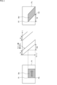
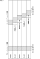
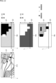
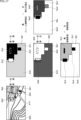
- FIGS. 1A and 1B are diagrams illustrating rolling shutter distortion.
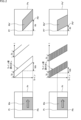
- FIG. 11 is a diagram illustrating thinning correction.
- FIG. 11 is a diagram illustrating frame interpolation correction.
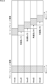
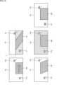
- 1A to 1C are diagrams illustrating an overview of a method for correcting rolling shutter distortion according to the present disclosure.
- FIG. 1 is a diagram illustrating an example of the configuration of an image processing system according to a preferred embodiment of the present disclosure.
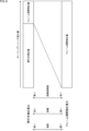
- 11A and 11B are diagrams illustrating weighting of thinning correction and frame interpolation correction.
- 11A and 11B are diagrams illustrating the amount of distortion correction per time for one line estimated from a target motion path for each subject.
- 11A and 11B are diagrams illustrating a distortion correction amount per line per time estimated from an estimated motion path of an imaging device.
- a figure explaining the distortion correction amount per unit time of one line which is the sum of the distortion amount per time of one line estimated from the estimated motion path of the imaging device and the distortion amount per time of one line estimated from the estimated motion path of the imaging device.
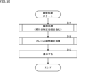
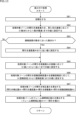
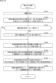
- 6 is a flowchart illustrating image processing by the image processing system of FIG. 5 .
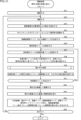
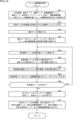
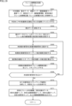
- 11 is a flowchart illustrating an imaging process (including a thinning-out correction process).
- 1A and 1B are diagrams illustrating examples of an RGB image and a corresponding velocity map, distance map, and distance confidence map; 13 is a flowchart illustrating a weighting process.
- 11 is a flowchart illustrating a frame interpolation correction process.
- FIGS. 11A to 11C are diagrams illustrating an overview of a modified example of the method for correcting rolling shutter distortion according to the present disclosure.
- 13 is a flowchart illustrating an imaging process (including a thinning-out correction process) in a modified example.
- 1A to 1C are diagrams illustrating an example of an RGB image and corresponding velocity map, distance map, distance confidence map, and weighting map.
- 13 is a flowchart illustrating a weighting process in a modified example.
- 11 is a flowchart illustrating a frame interpolation correction process.
- FIG. 1 is a diagram illustrating an example configuration of an application example of an image processing system according to the present disclosure.
- 13 is a flowchart illustrating a clonic convulsion monitoring process.
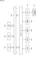
- FIG. 1 is a diagram illustrating an example of the configuration of a general-purpose computer.
- ⁇ Rolling shutter distortion> For example, consider a state in which a rectangular subject Mx is moving at a predetermined speed in the right direction indicated by the arrow in the real space Pr on the left side of Fig. 1. In this state, when the subject Mx is imaged by an imaging device made of a rolling shutter type image sensor, rolling shutter distortion occurs.
- Each pixel in the imaging element which is made up of multiple pixels arranged in a two-dimensional array, generates a pixel signal according to the amount of incident light from the real space Pr.
- the pixel signals of each pixel that constitutes the image sensor are read out sequentially in time series for each line on which the pixels are arranged.
- the vertical axis indicates lines and the horizontal axis indicates time, and the exposure period and readout timing of each pixel in units of a line are expressed. Note that in the center of Figure 1, the exposure period of the pixels that make up each line is expressed as period tp, and an example is shown in which the readout line order is from top to bottom.
- each pixel in a line starts from the top row. Then, after the exposure period tp has elapsed, each pixel in the top row is read out. After that, exposure starts for each pixel in the line below, and after the exposure period tp has elapsed, reading is performed. Next, exposure starts for each pixel in the line below, and after the exposure period tp has elapsed, reading is performed. The above process is repeated line by line.
- the exposure period and readout timing are gradually delayed from top to bottom in units of lines.
- the readout timing of the pixels capturing the upper left edge Pt of the subject Mx in real space Pr is delayed by a time tda, as shown in the center of Figure 1, relative to the readout timing of the pixels capturing the lower left edge Pb.
- the subject Mx is moving to the right in the figure at a predetermined speed, so even during the period in which the imaging element is capturing the image of the real space Pr, it will move to the right in the figure by the delay time tda.
- exposure begins at a position moved to the right from the upper left end Pt at a predetermined speed by the delay time tda, and reading is performed after the exposure period tp.
- the bottom left end Pb' of the image Mx' corresponding to the subject Mx is shifted from the top left end Pt' by a width da, which corresponds to the distance moved to the right in the figure by the delay time tda at a predetermined speed.
- All pixel signals constituting the image Mx' corresponding to the moving subject Mx are treated as an image that has moved to the right by the delay time, with each line being a unit. Therefore, in the real space Pr, the rectangular subject Mx is treated as an image Mx' that is distorted overall like a parallelogram on the image Ps that is the captured image.
- rolling shutter distortion The image distortion that occurs when capturing an image using the rolling shutter method is called rolling shutter distortion.
- ⁇ Thinning-out distortion correction> As a countermeasure against this rolling shutter distortion, generally known are rolling shutter distortion correction by a thinning method and rolling shutter distortion correction by a frame interpolation method.
- rolling shutter distortion correction by the thinning method will be referred to as thinning correction
- rolling shutter distortion correction by the frame interpolation method will be referred to as frame interpolation correction.
- Rolling shutter distortion is a phenomenon that occurs when pixels are read out line by line, as explained by showing the central part of Figure 1.
- Thinning-out correction is a correction that suppresses rolling shutter distortion by thinning out the number of lines to be read out, thereby shortening the overall readout time.
- Fig. 2 Note that the upper left, upper center, and upper right of Fig. 2 are the same as Fig. 1.
- the lower left of Fig. 2 is the same as the real space Pr of Fig. 1.
- the lower center of Fig. 2 is a diagram explaining thinning readout.
- the lower right of Fig. 2 is image Ps'', which is the imaging result corrected using the thinning method.
- Subject Mx is moving to the right in the figure at a predetermined speed.
- the lines of pixels to be read out are thinned out, resulting in a decrease in the overall number of lines to be read out.
- exposure begins at a position moved to the right from the top left end Pt at a predetermined speed by a delay time tdb ( ⁇ tda), and readout occurs after exposure period tp.
- the bottom left end Pb'' of image Mx'' is shifted from the top left end Pt'' by a width db ( ⁇ da) corresponding to the distance moved to the right in the figure by the delay time tdb ( ⁇ tda) at a specified speed.
- Frame interpolation distortion correction is a correction method that suppresses rolling shutter distortion by calculating the amount of correction per line using pixel signals from multiple consecutive frames and angular velocity and position information of the imaging device, and then performing frame interpolation by resampling to correct the pixel signals based on the calculated amount of correction.
- the correction amount per line is the sum of an estimated motion correction amount, which is the correction amount per line based on the actual movement of the imaging device when capturing an image estimated by a gyro sensor or the like, and a correction amount per line based on the target motion, which is the movement path of the subject.
- an estimated motion correction amount which is the correction amount per line based on the actual movement of the imaging device when capturing an image estimated by a gyro sensor or the like
- a correction amount per line based on the target motion which is the movement path of the subject.
- the estimated motion correction amount which is the correction amount per line
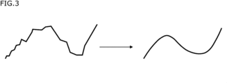
- the estimated motion correction amount is, for example, as shown in the left part of Figure 3, the detection results of a gyro sensor or the like actually detected by the imaging device when capturing an image, smoothed as shown in the right part of Figure 3.
- a gyro sensor or the like was mentioned above, this could also be an acceleration sensor, SLAM, or a combination of these.
- the amount of correction per line in the target movement which is the movement of the subject, becomes the target movement correction amount based on the target movement.
- the correction amount for each line is determined based on the estimated motion correction amount and the target motion correction amount. Then, by resampling according to the correction amount, rolling shutter distortion is suppressed.
- image M corresponding to subject Mo is captured with rolling shutter distortion like a parallelogram as it moves.
- images F1 and F2 corresponding to subjects F1o and F2o are not moving, so they are captured without rolling shutter distortion.
- image Pt is generated by applying thinning correction to image PI.
- image M corresponding to moving subject Mo is made into image Mt. This suppresses distortion in the horizontal direction. Images F1t and F2t corresponding to images F1 and F2 are left unchanged because no rolling shutter distortion occurs.
- thinning correction suppresses distortion depending on the number of lines to be read out and the number of lines to be thinned out. Therefore, the amount of distortion that can be suppressed is determined by the number of lines that can be thinned out. For this reason, when a relatively large amount of rolling shutter distortion has occurred, in order to completely suppress the distortion, it is necessary to thin out all of the lines between the first and last lines, which is not realistic. As a result, thinning correction cannot completely remove rolling shutter distortion from the image M of a moving subject Mo and the corresponding image Mt.
- image Pa is generated by applying frame interpolation correction to this image Pt.
- image Mt corresponding to subject Mo is made into an appropriately corrected image Ma.
- image Pa the images F1a and F2a are drawn as if a square flag has been distorted into a parallelogram. However, this does not depict the actual distortion that occurs, such as rolling shutter distortion, but merely indicates that an error such as Jello has occurred.
- a zone that exists for each subject is set on a line-by-line basis
- the weight (degree) of thinning correction and frame interpolation correction is set for each zone according to the speed, distance, and distance reliability of the subject within the zone, and the respective correction methods are combined to correct rolling shutter distortion.
- zone Zb below line L where image M and image F1 corresponding to moving subject Mo that can be set on a line-by-line basis exist image M corresponding to subject Mo that is large in size and moves at a predetermined speed exists, and image F1 that is small in size, distant, and not moving exists. Therefore, for example, the weight of the thinning correction and the weight of the frame interpolation correction are set in a balanced manner using the large-sized image Ma as the reference.
- the weight of the thinning correction is set high for image F2 present in zone Za, and the weight of the frame interpolation correction is set low, thereby suppressing the occurrence of errors such as Jello.
- the weight of the thinning correction and the weight of the frame interpolation correction are set in a balanced manner, making it possible to suppress rolling shutter distortion of the moving image Ma.
- the image processing system 101 in FIG. 3 is composed of an imaging device 111, a display processing unit 112, and cloud storage 113.
- the imaging device 111 is a camera that captures images using the so-called rolling shutter method, and captures RGB images while applying thinning rolling shutter correction according to the subject.
- the imaging device 111 identifies the amount of rolling shutter distortion, sets weights for thinning correction and frame interpolation correction, and controls the imaging of the RGB image so as to perform line thinning according to the weight of the thinning correction, thereby achieving thinning correction.
- the imaging device 111 sets the frame interpolation correction amount for the rolling shutter distortion amount according to the weight of the frame interpolation correction, and stores it in the memory unit 191 of the cloud storage 113 together with the RGB image captured in a thinning-corrected state.
- the display processing unit 112 acquires the RGB image and frame interpolation correction amount stored in the memory unit 191 of the cloud storage 113.
- the imaging device 111 may directly supply information on the RGB image and the frame interpolation correction amount to the display processing unit 112.
- the display processing unit 112 acquires the RGB image and the frame interpolation correction amount supplied from the imaging device 111.
- the display processing unit 112 acquires the RGB image captured with thinning correction applied and the frame interpolation correction amount, it applies frame interpolation correction to the RGB image captured with thinning correction applied based on the frame interpolation correction amount to generate and display a stabilized frame RGB image, and stores the generated stabilized frame RGB image in the memory unit 191 of the cloud storage 113.
- an image captured using the rolling shutter method is subjected to thinning correction and frame interpolation correction in an appropriate ratio according to the subject, generating a stabilized frame with the rolling shutter distortion corrected.
- the imaging device 111, display processing unit 112, and cloud storage 113 are described in detail below.
- the imaging device 111 generates a distance map, a distance confidence map, a speed map, a subject map (including subject information and a zone map, described later), thinning settings, imaging device information, motion data which is information on the position and orientation of the imaging device, weights for thinning correction and frame interpolation correction, and frame interpolation correction amount, which correspond to the captured RGB image, and outputs and stores them in the memory unit 191 in the cloud storage 113.
- the imaging device 111 When capturing RGB images as a video, the imaging device 111 generates a distance map, a distance confidence map, a speed map, a subject map (including subject information and a zone map, described later), thinning settings, imaging device information, motion data which is information on the position and orientation of the imaging device, weights for thinning correction and frame interpolation correction, and a frame interpolation correction amount, based on the timestamp assigned to each frame.
- the imaging device 111 includes a distance sensor 121, a distance map generating unit 122, an RGB sensor 123, an RGB image signal processing unit 124, a six-axis sensor 125, a motion detection unit 126, and a thinning correction unit 127.
- the distance sensor 121 is, for example, a LiDAR, a depth camera, or a stereo camera, and measures the distance to the subject in pixel units and outputs the pixel-by-pixel distance measurement results to the distance map generation unit 122.
- the distance map generation unit 122 generates a distance map by mapping the distances, which are the pixel-by-pixel distance measurement results supplied by the distance sensor 121, and outputs the distance map to the thinning correction unit 127.
- the RGB sensor 123 is an imaging element, such as a CMOS (Complementary Metal-Oxide-Semiconductor) image sensor or a CCD (Charge-Coupled Device) image sensor, and generates pixel signals according to the amount of incident light based on a predetermined RGB array, and outputs the signals to the RGB image signal processing unit 124.
- CMOS Complementary Metal-Oxide-Semiconductor
- CCD Charge-Coupled Device
- the RGB sensor 123 generates an RGB image signal by thinning out pixel signals in units of a predetermined number of lines based on the thinning settings provided by the thinning correction unit 127.
- the RGB image signal processing unit 124 performs a predetermined signal processing on the RGB pixel signals supplied by the RGB sensor 123 to generate an RGB image, and outputs the image to the thinning correction unit 127.
- the RGB image signal processing unit 124 When the RGB sensor 123 is performing thinning imaging based on the thinning setting, the RGB image signal processing unit 124 generates an RGB image by interpolating pixel signals of the thinned lines based on the thinning setting, and outputs the generated image to the thinning correction unit 127.
- the six-axis sensor 125 detects the acceleration and angular velocity in three axial directions (e.g., XYZ directions) of the imaging device 111 and outputs them to the motion detection unit 126.
- the motion detection unit 126 detects information about the position and orientation of the imaging device 111 in three-dimensional space based on the acceleration and angular velocity of the imaging device 111 in three-axis directions supplied by the six-axis sensor 125, and outputs this information to the thinning correction unit 127 as motion data of the imaging device 111.
- the thinning correction unit 127 obtains the distance map from the distance map generation unit 122, obtains the RGB image provided by the RGB image signal processing unit 124, and obtains the motion data of the imaging device 111 from the motion detection unit 126.
- the thinning correction unit 127 determines the thinning settings for the RGB sensor 123 based on the distance map, the RGB image, and the motion data of the imaging device 111, and controls the imaging of the imaging device 111.
- the thinning correction unit 127 generates a distance confidence map, a speed map, a subject map (including subject information), thinning settings, imaging device information, motion data which is information on the position and orientation of the imaging device, weights for each of the thinning correction and frame interpolation correction, and a frame interpolation correction amount based on the distance map, RGB image, and motion data of the imaging device 111, and outputs and stores them in the memory unit 191 in the cloud storage 113.
- the thinning correction unit 127 includes a semantic segmentation processing unit 141, a distance confidence map generating unit 142, a speed map generating unit 143, a weighting setting unit 144, a correction amount determining unit 145, and a thinning setting unit 146.
- the semantic segmentation processing unit 141 uses semantic segmentation to identify objects in an RGB image individually and on a pixel-by-pixel basis to generate an object map. Note that as long as it is possible to identify objects in an RGB image and generate an object map, it does not have to be semantic segmentation processing; for example, the semantic segmentation processing unit 141 may be configured with a DNN (Deep Neural Network), a recognizer, or AI (Artificial Intelligence) that has undergone machine learning to recognize objects, or it may use instance segmentation or panoptic segmentation.
- DNN Deep Neural Network
- AI Artificial Intelligence
- the distance reliability map generator 142 generates a distance reliability map in units of pixels from the magnitude of change in distance between frames in a time series of pixels that belong to the same subject, based on the subject map and the distance map. That is, if the distance information of pixels that belong to the same subject changes suddenly in the distance reliability map, the reliability of the distance information in the distance map is set low, and if the change in the distance information is gradual, the reliability of the distance information is set high.
- the velocity map generator 143 generates a velocity map by mapping the apparent velocity of each subject in units of pixels based on the positional changes of each subject in the RGB image between frames in a time series.
- the weighting setting unit 144 sets the range in which each subject exists in the RGB image as a zone in units of lines based on the RGB image, subject map, distance map, distance confidence map, and velocity map, generates a zone map, and sets weights for thinning correction and frame interpolation correction for each zone, setting the amount of correction for each.
- the weight setting unit 144 sets zones on a line-by-line basis based on the subject in the RGB image, as described with reference to FIG. 4, based on the subject map.
- Zones are set line by line, so if there are multiple subjects on the same line, there is a possibility that the same zone will contain multiple subjects.
- the weight setting unit 144 sets a reference subject from among multiple subjects present in the same zone based on a predetermined condition, and sets the zone based on the set reference subject.
- the predetermined condition may be based on the largest subject, a specific type of subject, the fastest subject, the subject with the highest distance reliability, or the closest subject in the same zone.
- the reference subject may also be set by comparing these multiple conditions.
- the weight setting unit 144 sets a reference subject under one of the conditions based on the RGB image, the subject map, the distance map, the distance confidence map, and the speed map, and sets the thinning correction amount for the zone based on the reference subject.
- the weight setting unit 144 sets weights based on the speed map, distance map, and distance reliability map so that the weight of the thinning correction amount increases as the speed of the reference subject increases, the distance decreases, and the distance reliability increases, as shown in FIG. 6, for example.
- FIG. 6 shows an example in which the thinning correction weight is set to a maximum of approximately 3/4, and conversely, the frame interpolation correction weight is set to a minimum of approximately 1/4.
- FIG. 6 shows an example in which the maximum weighting value for the amount of thinning correction is approximately 3/4, and the minimum weighting value for the amount of frame interpolation correction is approximately 1/4, but the maximum and minimum weighting values may be set in various ways based on the maximum amount of thinning correction used.
- weights related to the amount of thinning correction and the weights related to the amount of frame interpolation correction will be simply referred to as thinning correction weights and frame interpolation correction weights, and for simplicity's sake, they will be assumed to be set to values between 0 and 1.
- the weight setting unit 144 normalizes the speed histogram based on the speed map and sets the thinning speed weight. The faster the speed is, the closer the thinning speed weight is set to a value of 1, and the slower the speed is, the closer the thinning speed weight is set to a value of 0.
- the weight setting unit 144 normalizes the distance histogram based on the distance map and sets the thinning distance weight.
- the thinning distance weight is set to a value closer to 1 for shorter distances and closer to 0 for longer distances.
- the weight setting unit 144 normalizes the distance confidence histogram based on the distance confidence map and sets the thinned distance confidence weight.
- the thinned distance confidence weight is set to a value closer to 1 the higher the distance confidence, and is set to a value closer to 0 the lower the distance confidence.
- the weight setting unit 144 sets the thinning correction weight by multiplying the thinning speed weight, the thinning distance weight, and the thinning distance reliability weight.
- the weight setting unit 144 also sets the frame interpolation correction weight by subtracting the thinning correction weight from 1.
- the correction amount determination unit 145 calculates the amount of rolling shutter distortion for each subject for each zone, and determines the amount of thinning correction and the amount of frame interpolation correction by multiplying the amount of rolling shutter distortion for each subject by the weighting setting unit 144 set for each zone.
- the correction amount determination unit 145 calculates the thinning correction amount for each zone as the rolling shutter distortion amount x the thinning correction weight, and calculates the frame interpolation correction amount as the rolling shutter distortion amount x the frame interpolation correction weight.
- the amount of rolling shutter distortion (angle) for each subject is expressed as (the line direction angular velocity of the world coordinate system relative to the imaging device + the line direction angular velocity of each subject relative to the world coordinate system) x the read delay time per line before thinning.
- the amount of rolling shutter distortion (angle) for each subject is calculated from the motion data of the imaging device 111, the RGB image, the distance map, and the velocity map.
- the amount of rolling shutter distortion after thinning correction is applied is affected by the thinning in terms of the apparent angular velocity.
- the line direction angular velocity for each subject with respect to the world coordinate system is the apparent angular velocity per line for each subject's angle of view/thinning correction amount.
- the apparent angular velocity is multiplied by 4.
- the thinning setting unit 146 determines the specific number of lines to be thinned out based on the thinning correction amount determined by the correction amount determination unit 145 as the thinning setting, supplies this to the RGB sensor 123, and controls thinning imaging.
- the thinning setting unit 146 also supplies the thinning setting to the RGB image signal processing unit 124. That is, the RGB image signal processing unit 124 generates an RGB image by interpolating pixels of the thinned out lines using pixel signals from the RGB sensor 123 that have been thinned out based on the thinning setting.
- the display processing unit 112 is composed of a frame interpolation correction unit 161 and a display unit 162.
- the frame interpolation correction unit 161 reads out the RGB image, distance confidence map, speed map, subject map (including subject information and zone map), motion data, and frame interpolation correction amount from the memory unit 191 of the cloud storage 113, and applies frame interpolation correction to the thinned-out and corrected RGB image to generate a stabilized frame RGB image, which is output to the display unit 162 for display.
- the frame interpolation correction unit 161 stores stabilized motion data, which is motion data of the imaging device 111 corrected when generating the stabilized frame RGB image, a stabilized subject map, which is a subject map in the stabilized frame RGB image, a stabilized distance map corresponding to the stabilized frame RGB image, a stabilized distance reliability map, and a stabilization speed map in the memory unit 191 of the cloud storage 113.
- the frame interpolation correction unit 161 includes a motion path estimation unit 181, a target motion path estimation unit 182, and a motion correction unit 183.
- the motion path estimation unit 181 smoothes the motion of the imaging device 111 based on the motion data, which is time-series position and orientation data of the imaging device 111, and corrects the motion data.
- the motion path estimation unit 181 maps each pixel of the RGB image into a 3D space and matches the motion data for each frame in the time series based on the timestamp to estimate the motion path of the image capture device 111.
- the estimated motion path of the image capture device 111 is also referred to as the estimated motion path.
- the target motion path estimation unit 182 estimates the movement of a reference subject set for each zone as a target motion path based on the subject map, distance map, and information on each pixel of the RGB image mapped in 3D space.
- the motion correction unit 183 estimates the amount of correction per unit time for one line from the motion path of the imaging device 111 to a target motion path, which is the reference subject motion set for each zone. Then, based on the amount of correction per unit time for one line, the motion correction unit 183 resamples the RGB image so as to correct by the frame interpolation correction amount, thereby generating a stabilized frame RGB image.
- the apparent angular velocity (amount of distortion) per line relative to the subject's angle of view will be the angular velocity when the subject, the target, moves at a uniform linear speed with the imaging device 111 fixed.
- the angular velocity of the second line relative to the first line is expressed by angular velocity ⁇ 12
- the angular velocity of the third line relative to the second line is expressed by angular velocity ⁇ 23
- the angular velocity of the fourth line relative to the third line is expressed by angular velocity ⁇ 34
- the angular velocity of the fifth line relative to the fourth line is expressed by angular velocity ⁇ 45, as shown by the solid arrows in Figure 7.
- FIG. 7 shows the difference in the imaging position of a subject on lines 1 to 5 (lines 1 to 5) when the same subject moving to the right is imaged using the global shutter method and the rolling shutter method with the imaging device 111 fixed, with the left part being an example of the global shutter method and the right part being an example of the rolling shutter method.
- the global shutter method is a method in which no delay occurs on a line-by-line basis
- an example of the global shutter method is shown on the left side of FIGS. 7 to 9 to show a comparison between a case in which a delay occurs and a case in which there is no delay.
- the angular velocity in the line direction of the world coordinate system for the imaging device 111 will be the angular velocity when the imaging device 111 is panned to the right at uniform linear motion and captures an image of a fixed subject, that is, a target.
- FIG. 8 shows the difference in the position of the subject on lines 1 to 5 (lines 1 to 5) when the same fixed subject is imaged using the global shutter method and the rolling shutter method with the imaging device 111 panned to the right, with the left part being an example of the global shutter method and the right part being an example of the rolling shutter method.
- the amount of correction per unit time from the motion path of the imaging device 111 to the target motion path, which is the reference subject motion set for each zone can be estimated to be the sum of the amount of correction per unit time when the subject moves to the right with the imaging device 111 fixed, as indicated by the solid arrow, and the amount of correction per unit time when the imaging device 111 pans to the right, as indicated by the dotted arrow.
- the correction amount per unit time for one line of this block can be estimated to be the sum ⁇ + ⁇ ' of the angular velocity ⁇ , which is the correction amount per unit time for one line in the target movement, and the angular velocity ⁇ ', which is the correction amount per unit time for one line in the movement path of the imaging device 111.
- FIG. 9 shows the difference in the position of the subject on lines 1 to 5 when the imaging device 111 is panned to the right and the same subject moving to the right is imaged using the global shutter method and the rolling shutter method, with the left part being an example of the global shutter method and the right part being an example of the rolling shutter method.
- each path is uniform linear motion, but this is not limited to the above, and it may be estimated as uniform rotational motion, or as a combination of uniform linear motion and uniform rotational motion, or in particular, the uniform rotational motion may be estimated as pendulum motion seen from the side, or in particular as pendulum motion at the same distance from the fulcrum, or in particular as arm clonic convulsions, which are pendulum motion of the arm with the elbow as the fulcrum, or as leg clonic convulsions, which are pendulum motion of the leg with the knee as the fulcrum.
- the motion correction unit 183 estimates the amount of correction per unit time from the motion path of the imaging device 111 to the target motion path, which is the reference subject motion set for each zone. Furthermore, the motion correction unit 183 resamples the RGB image so as to correct by the frame interpolation correction amount based on the correction amount per unit time, to generate a stabilized frame RGB image, which is output to the display unit 162 for display.
- the motion correction unit 183 When generating the stabilized frame RGB image, the motion correction unit 183 generates a stabilized subject map, which is a subject map in the stabilized frame RGB image, a stabilized distance map corresponding to the stabilized frame RGB image, a stabilized distance reliability map, and a stabilization speed map based on the positional relationship of each pixel in the resampled RGB image. The motion correction unit 183 then stores the various generated maps together with stabilized motion data, which is the motion data of the imaging device 111 corrected when generating the stabilized frame RGB image, in the storage unit 191 of the cloud storage 113.
- step S11 the imaging device 111 executes imaging processing including thinning-out rolling shutter correction processing, applies thinning-out correction while capturing RGB images in successive frame units, and outputs and stores the imaging results in the memory unit 191 in the cloud storage 113.
- the imaging device 111 generates weights for the thinning correction and frame interpolation correction, and a frame interpolation correction amount, for each zone in which a subject exists in the RGB image, and corrects the rolling shutter distortion by capturing the RGB image while applying thinning correction by the distortion correction amount corresponding to the thinning correction weight.
- the imaging device 111 also generates a distance map, a distance confidence map, a speed map, a subject map (including subject information and zone map), thinning settings, imaging device information, motion data which is information on the position and orientation of the imaging device, weights for thinning correction and frame interpolation correction for each zone in which a subject exists in the RGB image, and a frame interpolation correction amount, which correspond to the captured RGB image, and outputs these to the memory unit 191 in the cloud storage 113 for storage.
- step S12 the display processing unit 112 executes frame interpolation correction processing, acquires an RGB image from the memory unit 191 in the cloud storage 113, applies frame interpolation correction, and generates a stabilized frame RGB image.
- the display processing unit 112 generates a stabilized frame RGB image by resampling and correcting the RGB image that has been subjected to thinning correction using frame interpolation correction by the frame interpolation correction amount that is set based on the respective weights of the thinning correction and the frame interpolation correction supplied from the imaging device 111.
- the display processing unit 112 also generates stabilized motion data, which is motion data of the imaging device 111 corrected when resampling the stabilized frame RGB image, a stabilized subject map, which is a subject map in the stabilized frame RGB image, a stabilized distance map corresponding to the stabilized frame RGB image, a stabilized distance reliability map, and a stabilization speed map, and stores them in the memory unit 191 of the cloud storage 113.
- stabilized motion data which is motion data of the imaging device 111 corrected when resampling the stabilized frame RGB image
- a stabilized subject map which is a subject map in the stabilized frame RGB image
- a stabilized distance map corresponding to the stabilized frame RGB image a stabilized distance reliability map
- a stabilization speed map a stabilization speed map
- step S13 the display processing unit 112 outputs the generated stabilized frame RGB image to the display unit 162 for display.
- weights for thinning correction and frame interpolation correction are set for each zone in which a subject exists in the RGB image, and an image is captured with thinning settings made according to the set weights, resulting in an RGB image being captured with thinning correction applied.
- a stabilized frame RGB image is generated and displayed by applying frame interpolation correction corresponding to the weighting set for the frame interpolation correction to the RGB image that has been subjected to thinning correction according to the weighting.
- step S31 the RGB sensor 123 generates RGB pixel signals according to the amount of incident light, and outputs them to the RGB image signal processing unit 124.
- the RGB image signal processing unit 124 generates an RGB image by performing a predetermined signal processing on the RGB pixel signals supplied from the RGB sensor 123, and outputs the RGB image to the thinning correction unit 127.
- step S31 may be repeated until the multiple frames required for the process are captured.
- the RGB image signal processing unit 124 since no thinning setting is made in the initial processing, the RGB image signal processing unit 124 generates an unthinned RGB image and outputs it to the thinning correction unit 127.
- step S32 the distance sensor 121 measures the distance to the subject and outputs the pixel-by-pixel distance measurement results to the distance map generation unit 122.
- the distance map generation unit 122 generates a distance map based on the pixel-by-pixel distance measurement results supplied by the distance sensor 121, and outputs the distance map to the thinning correction unit 127.
- the six-axis sensor 125 detects the acceleration and angular velocity of the imaging device 111 in three-axis directions and outputs them to the motion detection unit 126.
- the motion detection unit 126 detects information on the position and orientation of the imaging device 111 in three-dimensional space based on the acceleration and angular velocity of the imaging device 111 in the three-axis directions supplied by the six-axis sensor 125, and outputs this information to the thinning correction unit 127 as motion data of the imaging device 111.
- the motion detection unit 126 converts the detection results in the local coordinate system supplied by the six-axis sensor 125 into the world coordinate system to generate motion data.
- step S34 the semantic segmentation processing unit 141 performs semantic segmentation based on the RGB image, identifies individual objects in the image, and generates a subject map.
- the distance confidence map generating unit 142 generates a distance confidence map by mapping the distance confidence from the magnitude of change in distance over time of pixels belonging to the same subject based on the subject map and the distance map, so that the smaller the change in pixel unit, the higher the confidence.
- the velocity map generating unit 143 generates a velocity map by mapping the velocity in pixel units for each subject from the position change of each subject in the RGB image between frames in the time series.
- step S36 the weight setting unit 144 sets zones line by line based on the subject in the RGB image based on the subject map, and generates a zone map that groups the zones together.
- the weighting setting unit 144 sets the range above the line L on which the airplane is located as zone Z1, and sets the range below the line L as zone Z2.
- the velocity map, distance map, and distance confidence map are expressed, for example, as the velocity map Mv, distance map Md, and distance confidence map Mc in FIG. 12.
- image P11 which is an RGB image
- the main body of the airplane is close to the imaging position, so the main body of the airplane is represented in white and the distant background is represented in gray.
- the distance reliability map Mc the higher the reliability of the distance, the whiter the corresponding area is displayed as a distribution, and the lower the reliability of the distance, the darker the corresponding area is displayed.
- image P11 which is an RGB image
- the background position changes little, so it is displayed in white
- the airplane body, which changes little next, is displayed in gray
- the propellers, wheels, and windows, which tend to blend in with the background are displayed in black due to the large changes in their vicinity.
- step S37 the weight setting unit 144 sets one of the unprocessed zones as the zone to be processed.
- step S38 the correction amount determination unit 145 calculates the amount of rolling shutter distortion (angle) based on the reference object present in the processing target zone.
- the amount of rolling shutter distortion (angle) for each object is expressed as (the line direction angular velocity of the world coordinate system relative to the image capture device 111 + the line direction angular velocity of the object relative to the world coordinate system) x the read delay time per line.
- the correction amount determination unit 145 determines the line direction angular velocity of the world coordinate system relative to the image capture device 111 based on the motion data of the image capture device 111, and determines the line direction angular velocity of the subject relative to the RGB image world coordinate system based on the time series velocity map.
- the correction amount determination unit 145 also calculates the read delay time per line by multiplying the exposure time in the RGB sensor 123 by a unique coefficient that is pre-stored as information about the image capture device 111.
- the amount of rolling shutter distortion in frames after thinning correction is applied is affected by the thinning in terms of the apparent angular velocity.
- the line-direction angular velocity for each subject relative to the world coordinate system must be the apparent angular velocity per line relative to the subject's angle of view/thinning amount. In other words, for example, if the thinning amount is set to 1/4 of all lines, the line-direction angular velocity for each subject relative to the world coordinate system is multiplied by 4.
- step S39 the weight setting unit 144 executes a weighting process and sets the weights for each of the thinning correction and the frame interpolation correction.
- step S40 the correction amount determination unit 145 determines the thinning correction amount and the frame interpolation correction amount by multiplying the rolling shutter distortion amount of the processing target zone by the weighting setting unit 144 set for each zone.
- the correction amount determination unit 145 calculates the thinning correction amount for the processing target zone as the rolling shutter distortion amount x the weight of the thinning correction amount, and calculates the frame interpolation correction amount as the rolling shutter distortion amount x the weight of the frame interpolation correction amount.
- step S41 the weight setting unit 144 determines whether or not there are any unprocessed zones. If there are any unprocessed zones, the process returns to step S37. That is, the weights of the thinning correction and frame interpolation correction are set for all zones, and the processes from step S37 to S41 are repeated until the amounts of thinning correction and frame interpolation correction are determined.
- step S41 weights for thinning correction and frame interpolation correction are set for all zones, the amounts of thinning correction and frame interpolation correction are determined, and if it is determined that there are no unprocessed zones, processing proceeds to step S42.
- step S42 the thinning setting unit 146 determines the number of lines to be thinned out in the imaging of the RGB sensor as the thinning setting based on the thinning correction amount, and controls the RGB sensor 123 to capture an image based on the thinning setting. In other words, if the thinning setting is set here, thinned imaging will be performed from then on. At this time, the thinning setting unit 146 also outputs the thinning setting, which is information on the number of lines to be thinned out, to the RGB image signal processing unit 124.
- step S43 the RGB image signal processing unit 124 generates an RGB image by interpolating pixel signals of the lines thinned out by the RGB sensor 123 based on the thinning setting, and outputs the image to the thinning correction unit 127.
- the thinning correction unit 127 stores the thinning-corrected RGB image, the motion data of the imaging device 111, the distance map, the distance confidence map, the speed map, the subject map (including subject information and zone map), imaging device information (exposure time during imaging and delay time per line), and the frame interpolation correction amount (including information on the weight of the frame interpolation correction) in the memory unit 191 of the cloud storage 113.
- the thinning correction unit 127 may directly output the thinning-corrected RGB image, the motion data of the imaging device 111, the distance map, the distance confidence map, the speed map, the subject map (including the subject information and the zone map), the imaging device information (the exposure time during imaging and the delay time per line), and the frame interpolation correction amount for each zone set based on the subject (including information on the weight of the frame interpolation correction) to the frame interpolation correction unit 161 of the display processing unit 112.
- step S45 it is determined whether or not an instruction to end the process has been given. If an instruction to end the process has not been given, the process returns to step S32 and the subsequent steps are repeated.
- step S45 if an instruction to end the process is given, the process ends.
- weights for thinning correction and frame interpolation correction are set for each zone based on the RGB image, distance map, and motion data, the amount of thinning correction and the amount of frame interpolation correction are determined according to the set weights, and an RGB image that has been thinning-corrected according to the amount of thinning correction is captured. Then, the thinning-corrected RGB image, motion data of the imaging device 111, distance map, distance reliability map, speed map, subject map (including subject information and zone map), imaging device information (exposure time during imaging and delay time per line), and frame interpolation correction amount for each zone are stored in the memory unit 191 of the cloud storage 113.
- step S61 the weight setting unit 144 initializes the thinning correction weight, which is the weight for the thinning correction of the processing target zone, and sets it to 0.
- step S62 the weight setting unit 144 sets the thinning speed weight of the processing target zone according to the apparent speed, with the higher the speed being closer to 1 and the lower the speed being closer to 0. In other words, by setting the thinning correction weight larger according to the speed, it becomes possible to suppress the rolling shutter distortion that is larger at higher speeds.
- the weight setting unit 144 sets a weight such that the thinning speed weight is minimized based on the speed at which the area of the nearest airplane is represented in black with the largest area.
- the weight setting unit 144 sets the thinning speed weight based on the speed represented in gray.
- step S63 the weight setting unit 144 determines whether the movement of the subject that is the reference for the processing target zone is in line with the movement of the imaging device 111, based on the movement data of the imaging device 111.
- step S63 if the movement of the subject that is the reference for the processing target zone is a movement that follows the movement of the imaging device 111, processing proceeds to step S64.
- the movement of the subject that is the reference for the processing target zone is a movement that follows the movement of the imaging device 111, but this may also be the case when recording at a low resolution such as HD (High Definition), or when performing image processing for monitoring, or a combination of these.
- step S64 the weight setting unit 144 sets the thinning speed weight for the processing target zone to a value close to 1.
- step S64 if the movement of the subject that is the reference for the processing target zone does not match the movement of the imaging device 111, the processing of step S64 is skipped. In other words, in this case, a thinning speed weight according to the apparent speed is set.
- step S65 the weight setting unit 144 sets the thinning distance weight for the processing target zone based on the distance map so that the farther the distance is, the closer it is to 0, and the closer it is to 1. In other words, when the distance is close, the occurrence of jello can be suppressed by reducing the weight of the frame interpolation correction.
- the weight setting unit 144 sets a weight such that the thinning distance weight is maximized based on the distance to the closest position represented by the white color of the airplane body.
- the weight setting unit 144 sets the thinning distance weight based on the distance represented in gray.
- step S66 the weight setting unit 144 sets the thinning distance confidence weight for the processing target zone to a value closer to 0 the lower the distance confidence, and to a value closer to 1 the higher the distance confidence, based on the distance confidence map.
- the distance confidence is low and it is necessary to consider the possibility that the distance is close, it is possible to suppress the occurrence of jello by reducing the weight of the frame interpolation correction.
- the weight setting unit 144 sets the thinning distance confidence weight based on the distance confidence of the main body of the airplane that is expressed in the widest range of gray.
- the weight setting unit 144 sets the thinning distance reliability weight based on the distance reliability represented in light gray.
- step S67 the weight setting unit 144 calculates the thinning weight by multiplying the thinning speed weight, the thinning distance weight, and the thinning distance reliability weight.
- step S68 the weight setting unit 144 calculates the frame interpolation weight, which is the weight for the frame interpolation correction, by subtracting the thinning weight from 1.
- a thinning correction weight and a frame interpolation correction weight are set based on the speed map, distance map, and distance reliability map in the area where the reference subject that constitutes the zone exists.
- the faster the speed of the reference subject, the closer the distance value of the reference subject, and the higher the reliability of the distance reliability map of the reference subject the larger the thinning weight, which is the weight for the thinning correction, is set, and the smaller the frame interpolation weight, which is the weight for the frame interpolation correction, is set.
- the weighting related to the amount of thinning correction is set to, for example, at most 3/4, and conversely, the weighting related to the amount of frame interpolation correction is at most 1/4.
- FIG. 6 shows an example in which the maximum weighting value for the amount of thinning correction is approximately 3/4, and the minimum weighting value for the amount of frame interpolation correction is approximately 1/4, but the maximum and minimum weighting values may be set in various ways based on the maximum value of the amount of thinning correction used.
- step S81 the frame interpolation correction unit 161 of the display processing unit 112 reads and acquires the thinning-corrected RGB image stored in the memory unit 191 of the cloud storage 113, the motion data of the imaging device 111, the distance map, the distance reliability map, the speed map, the subject map, imaging device information (exposure time during imaging and delay time per line), and the frame interpolation correction amount (including information on the weight of the frame interpolation correction).
- step S82 the motion path estimation unit 181 maps each pixel of the RGB image into 3D space.
- step S83 the motion path estimation unit 181 smoothes the motion of the image capture device 111 based on the motion data, which is time-series position and orientation data of the image capture device 111, and corrects the motion data.
- step S84 the motion path estimation unit 181 matches the motion data for each frame in the time series based on the timestamps, and estimates the motion path of the imaging device 111.
- step S85 the target motion path estimation unit 182 sets the unprocessed zone as the zone to be processed.
- step S86 the target motion path estimation unit 182 estimates the movement of the reference subject set in the processing target zone as the target motion path based on the subject map, the distance map, and information on each pixel of the RGB image mapped in 3D space.
- step S87 the motion correction unit 183 estimates the amount of correction per unit time for one line from the estimated motion path of the imaging device 111 to the target motion path, which is the reference subject motion set in the processing target zone.
- step S88 the motion correction unit 183 resamples the RGB image so as to correct it by the frame interpolation correction amount based on the correction amount per unit time of one line calculated in the processing of step S87, and generates a stabilized frame RGB image of the processing target zone.
- step S89 the motion correction unit 183 determines whether or not there are any unprocessed zones.
- step S89 If there are any unprocessed zones in step S89, processing returns to step S85.
- steps S85 to S89 are repeated until stabilized frame RGB images are generated for all zones.
- step S89 the motion correction unit 183 generates a complete stabilized frame RGB image by synthesizing the stabilized frame RGB images of all zones.
- step S91 when generating a stabilized frame RGB image, the motion correction unit 183 generates a stabilized subject map, which is a subject map in the stabilized frame RGB image, a stabilization distance map corresponding to the stabilized frame RGB image, a stabilization distance reliability map, and a stabilization speed map based on the positional relationship of each pixel in the RGB image generated by resampling, and stores these in the memory unit 191 of the cloud storage 113 together with stabilized motion data, which is the motion data of the imaging device 111 corrected when generating the stabilized frame RGB image.
- a stabilized subject map which is a subject map in the stabilized frame RGB image
- a stabilization distance map corresponding to the stabilized frame RGB image a stabilization distance reliability map
- a stabilization speed map based on the positional relationship of each pixel in the RGB image generated by resampling
- frame interpolation correction is performed on the thinning-corrected RGB image, making it possible to perform rolling shutter correction that combines both thinning correction and frame interpolation correction based on the thinning weight and frame interpolation weight that are set based on the subject's speed, distance, and distance reliability.
- VFX Visual Effects
- this can also be used for clonic convulsion monitoring, which will be described later as an application example, or for photogrammetry, or for any video that requires accurate, measurable precision without the use of blur to depict fast-moving subjects, particularly subjects that move in uniform rotational motion, pendulum motion, or pendulum motion around a fulcrum, which conventional technology struggles to achieve.
- the image processing system 101 is configured in a state in which the imaging device 111, the display processing unit 112, and the cloud storage 113 are each capable of communicating with each other over a network.
- a configuration having the functions realized by the imaging device 111, the display processing unit 112, and the cloud storage 113 may be configured within hardware consisting of a single housing, such as a personal computer, a smartphone, or a new imaging device that includes the imaging device 111.
- thinning correction and frame interpolation correction can be combined according to the weights to appropriately suppress rolling shutter distortion.
- the weights of the thinning correction and the frame interpolation correction may be set based on the speed, distance, and distance reliability of each of the subjects.
- the occurrence of jello can be suppressed by increasing the weight of the thinning correction and decreasing the weight of the frame interpolation correction.
- the weights of the thinning-out correction and the inter-frame correction are appropriately set according to the speed, distance, and distance reliability of the subject, making it possible to appropriately combine thinning-out correction and frame interpolation correction for each subject, thereby making it possible to appropriately suppress rolling shutter distortion.
- steps S111 to S115 and from steps S121 to S124 in FIG. 16 are similar to the processes from steps S31 to S35 and from steps S42 to S45 in the flowchart in FIG. 11, so their explanation will be omitted.
- an RGB image such as that shown in image P11' in Figure 17 is captured, and five subjects are recognized as subjects, namely subject Sb1 corresponding to the body of the airplane in image P11, subject Sb2 corresponding to the propeller, subject Sb3 corresponding to the window, subject Sb4 corresponding to the wheels, and subject Sb5 corresponding to the background.
- the velocity map, distance map, and distance confidence map are expressed, for example, as the velocity map Mv', distance map Md', and distance confidence map Mc' in FIG. 17.
- the velocity map Mv' in image P11' which is an RGB image
- velocity distributions Sv1 to Sv5 corresponding to subjects Sb1 to Sb5 are set.
- image P11' which is an RGB image
- distance distributions Sd1 to Sd5 corresponding to subjects Sb1 to Sb5 are set.
- the distance confidence map Mc' the higher the confidence of the distance, the whiter the corresponding area is represented, and the lower the confidence of the distance, the blacker the corresponding area is represented.
- image P11' which is an RGB image
- distance confidence distributions Sc1 to Sc5 corresponding to subjects Sb1 to Sb5 are set.
- step S116 the weight setting unit 144 sets one of the unprocessed subjects as the subject to be processed.
- step S117 the correction amount determination unit 145 calculates the amount of rolling shutter distortion (angle) based on the subject to be processed. Note that the specific method of calculating the amount of rolling shutter distortion (angle) is the same as when the zone is used as a unit, so a description thereof will be omitted.
- step S118 the weight setting unit 144 executes weighting processing to set weights for the thinning correction and frame interpolation correction of the subject to be processed.
- step S119 the correction amount determination unit 145 determines the thinning correction amount and the frame interpolation correction amount by multiplying the amount of rolling shutter distortion of the subject to be processed by the weighting setting unit 144 set for the subject to be processed.
- step S120 the weight setting unit 144 determines whether or not there are any unprocessed subjects, and if there are any unprocessed subjects, the process returns to step S116. That is, the weights of the thinning correction and the frame interpolation correction are set for all the subjects, and the processes from step S116 to S120 are repeated until the amounts of the thinning correction and the frame interpolation correction are determined.
- step S120 weights for thinning correction and frame interpolation correction are set for all subjects, the amounts of thinning correction and frame interpolation correction are determined, and if it is determined that there are no unprocessed subjects, processing proceeds to step S121.
- the RGB sensor 123 is controlled so that the set number of lines are thinned based on the thinning correction amount set for each subject, thinned image capture is performed, and the pixels of the thinned lines are generated by interpolation, and an RGB image with corrected thinning is captured.
- the thinning correction unit 127 stores the thinning-corrected RGB image, the motion data of the imaging device 111, the distance map, the distance confidence map, the speed map, the subject map, imaging device information (exposure time during imaging and delay time per line), and the frame interpolation correction amount for each subject (including information on the weight of the frame interpolation correction) in the memory unit 191 of the cloud storage 113.
- the thinning correction unit 127 may directly output the thinning-corrected RGB image, the motion data of the imaging device 111, the distance map, the distance reliability map, the speed map, the subject map, imaging device information (exposure time during imaging and delay time per line), and the frame interpolation correction amount for each subject (including information on the weight of the frame interpolation correction) to the frame interpolation correction unit 161 of the display processing unit 112.
- weights for thinning correction and frame interpolation correction are set for each subject based on the RGB image, distance map, and motion data, the amount of thinning correction and the amount of frame interpolation correction according to the set weights are determined for each subject, and an RGB image that has been thinning-corrected according to the amount of thinning correction for each subject is captured. Then, the thinning-corrected RGB image, motion data of the imaging device 111, distance map, distance reliability map, speed map, subject map, imaging device information (exposure time during imaging and delay time per line), and frame interpolation correction amount (including information on the weight of frame interpolation correction) are stored in the memory unit 191 of the cloud storage 113.
- the weighting process in the modified example will be described with reference to the flowchart of Fig. 18.
- the weighting process in the modified example is a process in which the processing target is a subject
- the weighting process described with reference to Fig. 13 is a process in which the processing target is a zone.
- step S141 the weight setting unit 144 initializes the thinning weight, which is the weight for the thinning correction of the subject to be processed, and sets it to 0.
- step S142 the weight setting unit 144 sets the thinning speed weight of the subject to be processed based on the speed map, in accordance with the apparent speed, so that the higher the speed, the closer to 1, and the lower the speed, the closer to 0.
- the weight setting unit 144 sets the thinning speed weight based on the speed represented by the color in the velocity distribution Sv1 to Sv5 of the corresponding velocity map Mv'.
- step S143 the weight setting unit 144 determines whether the movement of the subject to be processed is in accordance with the movement of the imaging device 111, based on the movement data of the imaging device 111.
- step S143 the movement of the subject being processed is in accordance with the movement of the imaging device 111, the process proceeds to step S144.
- step S144 the weight setting unit 144 sets the thinning speed weight of the subject to be processed to a value close to 1.
- step S144 if the movement of the subject to be processed does not match the movement of the image capture device 111, the process of step S144 is skipped. In other words, in this case, a thinning speed weight according to the apparent speed is set.
- step S145 the weight setting unit 144 sets the thinning distance weight for the processing target subject to a value closer to 0 the farther the distance is, and a value closer to 1 the closer the distance is, based on the distance map.
- the weight setting unit 144 sets the thinning distance weight based on the distance represented by the color in the distance distribution Sd1 to Sd5 of the corresponding distance map Md'.
- step S146 the weight setting unit 144 sets the thinning distance confidence weight for the processing target subject to a value closer to 0 the lower the confidence, and to 1 the higher the confidence, based on the distance confidence map.
- the weight setting unit 144 sets the thinning distance confidence weight based on the distance confidence represented by the color in the distance confidence distribution Sc1 to Sc5 of the corresponding distance confidence map Mc'.
- step S147 the weight setting unit 144 calculates the thinning weight of the subject to be processed by multiplying the thinning speed weight, the thinning distance weight, and the thinning reliability weight.
- step S148 the weight setting unit 144 subtracts the thinning weight from 1 to calculate the frame interpolation weight, which is the weight for the frame interpolation correction of the subject to be processed.
- a thinning weight which is the weight for the thinning correction
- a frame interpolation weight which is the weight for the frame interpolation correction
- the thinning weights of all subjects are mapped in association with the RGB image, resulting in, for example, the thinning weight map Mw in FIG. 17.
- subject Sb1 which corresponds to the main body of the airplane, is moving but at a low speed and is also close, so the thinning weight Sw1 for the corresponding area is set small and the area is colored dark gray.
- the distance reliability Sv2 is extremely low, so it is colored black, the thinning weight Sw2 is minimized, and the frame interpolation correction is maximized.
- subject Sb2 corresponding to the propeller would be white and the thinning correction would be maximized, but a frame with extremely low distance reliability is shown as an example to show that jello does not occur even in a frame with extremely low distance reliability.
- the background weight Sw2 would also be minimized and the frame interpolation correction would be maximized, resulting in jello in which the background shakes due to the movement of the propeller.
- the processing of steps S64 and S144 makes it possible to always suppress jello even in an implementation in which the distance reliability shakes.
- Subject Sb3 corresponding to the window and subject Sb4 corresponding to the wheels are moving at a low speed and have low distance reliability, so the thinning weights Sw3 and Sw4 are set small and are colored light gray.
- Subject Sb5 which corresponds to the background, is relatively far away and moves slowly, but the distance confidence is high, so the thinning weight Sw5 is set high and the subject is colored white.
- the thinning weight which is the weight for the thinning correction
- the frame interpolation weight which is the weight for the frame interpolation correction
- step S161 the frame interpolation correction unit 161 of the display processing unit 112 reads and acquires the thinning-corrected RGB image stored in the memory unit 191 of the cloud storage 113, the motion data of the imaging device 111, the distance map, the distance reliability map, the speed map, the subject map, imaging device information (exposure time during imaging and delay time per line), and the frame interpolation correction amount for each subject (including information on the weight of the frame interpolation correction).
- step S162 the motion path estimation unit 181 maps each pixel of the RGB image into 3D space.
- step S163 the motion path estimation unit 181 smoothes the motion of the image capture device 111 based on the motion data, which is data on the time series position and orientation of the image capture device 111, and corrects the motion data.
- step S164 the motion path estimation unit 181 matches the motion data for each frame in the time series based on the timestamps, and estimates the motion path of the imaging device 111.
- step S165 the target motion path estimation unit 182 sets the unprocessed subject as the subject to be processed.
- step S166 the target motion path estimation unit 182 estimates the motion of the subject to be processed as a target motion path based on the subject map, the distance map, and information on each pixel of the RGB image mapped in 3D space.
- step S167 the motion correction unit 183 estimates the amount of correction per unit time for one line from the estimated motion path of the image capture device 111 to the target motion path, which is the motion of the subject to be processed.
- step S168 the motion correction unit 183 resamples the RGB image so as to correct it by the frame interpolation correction amount based on the correction amount per unit time of one line, and generates a stabilized frame RGB image of the subject to be processed.
- step S169 the motion correction unit 183 determines whether or not there are any unprocessed subjects.
- step S169 If there are any unprocessed subjects in step S169, processing returns to step S165.
- steps S165 to S169 are repeated until stabilized frame RGB images are generated for all subjects.
- step S170 the motion correction unit 183 generates a complete stabilized frame RGB image by combining the stabilized frame RGB images of all the subjects.
- step S171 when generating a stabilized frame RGB image, the motion correction unit 183 generates a stabilized subject map, which is a subject map in the stabilized frame RGB image, a stabilization distance map corresponding to the stabilized frame RGB image, a stabilization distance reliability map, and a stabilization speed map based on the positional relationship of each pixel in the RGB image generated by resampling, and stores these in the memory unit 191 of the cloud storage 113 together with stabilized motion data, which is the motion data of the imaging device 111 corrected when generating the stabilized frame RGB image.
- a stabilized subject map which is a subject map in the stabilized frame RGB image
- a stabilization distance map corresponding to the stabilized frame RGB image a stabilization distance reliability map
- a stabilization speed map based on the positional relationship of each pixel in the RGB image generated by resampling
- frame interpolation correction is applied to the thinning-corrected RGB image, making it possible to perform rolling shutter correction that combines thinning correction and frame interpolation correction for each subject based on the thinning weight and frame interpolation weight that are set based on the speed, distance, and distance reliability.
- VFX Visual Effects
- convulsion monitoring which is an application example described below
- photogrammetry or any other video that requires accurate, measurable precision without the use of blur to depict fast-moving subjects, particularly subjects that move in uniform rotational motion, pendulum motion, or pendulum motion around a fulcrum, which conventional technology struggles to achieve.
- image processing is realized that corrects rolling shutter distortion and generates and displays a stabilized frame RGB image, and as by-products, the stabilized frame RGB image, stabilized motion data, stabilized subject map, stabilization distance map, stabilization distance reliability map, and stabilization speed map are sequentially stored as metadata in the memory unit 191 of the cloud storage 113.
- the metadata stored in this way may be used to realize other processes.
- Metadata can be used to identify and individually identify people among the subjects in the stabilized frame RGB image, and estimate bone structure and height to monitor convulsions and determine whether they are clonic convulsions caused by a cardiac disorder, shivers caused by cold that occur in healthy people, or essential tremors that occur in healthy elderly people.
- Figure 20 shows an example of the configuration of an image processing system that uses metadata generated by image processing to correct rolling shutter distortion to monitor clonic convulsions caused by cardiac disorders.
- the image processing system 101' in FIG. 20 differs from the image processing system 101 in FIG. 5 in that it is newly equipped with a cardiogenic malfunction monitoring processing unit 211.
- the cardiogenic disorder monitoring processing unit 211 monitors the presence or absence of clonic convulsions caused by cardiogenic disorders based on the metadata generated when the above-mentioned image processing is performed to correct rolling shutter distortion and display the image.
- the cardiogenic malfunction monitoring processing unit 211 first acquires the stabilized frame RGB image, stabilized object map, stabilized velocity map, and stabilized distance map stored in the memory unit 191 of the cloud storage 113.
- the cardiogenic disorder monitoring processing unit 211 estimates the limb skeleton for each person based on the subject map and the velocity map, calculates the convulsion velocity of the limb skeleton, and compares it with a convulsion velocity threshold to determine whether clonic convulsions caused by a cardiogenic disorder are occurring.
- clonic convulsions could be determined by simply measuring the speed of the limb skeleton convulsions, but this required an evaluation based on the person's height, making it impossible to determine whether the tremor was due to cold, which occurs in healthy people, or essential tremor, which occurs in healthy elderly people, or whether it was clonic convulsions.
- Patent No. 6372388 proposes a technology that distinguishes between tremors, i.e., essential tremor, and convulsions, i.e., clonic convulsions, by detecting both the posture and direction of the fall.
- tremors i.e., essential tremor
- convulsions i.e., clonic convulsions
- Patent No. 6538055 proposes a technology that can distinguish between essential tremor and clonic convulsions even while the patient is in bed by also detecting EMG (surface myoelectric potential) signal data.
- EMG surface myoelectric potential
- a contact-type device had to be worn in order to make the diagnosis while the patient was in bed.
- the image processing system 101' of FIG. 20 of the present disclosure it is possible to set a threshold value for clonic convulsions according to the height of each person based on the metadata generated when the above-mentioned image processing is performed to correct the rolling shutter distortion and display the image. Therefore, it is possible to appropriately monitor the presence or absence of clonic convulsions even when the person is lying down in bed and without wearing a contact-type device.
- This processing is premised on the fact that image processing has been performed to correct and display the above-mentioned rolling shutter distortion. It is also premised on the fact that processing has been performed that combines thinning correction for each subject, as explained in the modified example, and frame interpolation correction.
- step S201 the cardiogenic malfunction monitoring processing unit 211 reads and acquires the stabilized frame RGB image, stabilized motion data, stabilized distance map, stabilized velocity map, and stabilized object map stored in the memory unit 191 of the cloud storage 113.
- step S202 the cardiogenic disorder monitoring processing unit 211 maps each pixel of the RGB image into a normalized 3D space.
- step S203 the cardiac disorder monitoring processing unit 211 individually identifies and extracts people from among the subjects based on the stabilized subject map, and estimates and stores the bone structure and height of each person based on the stabilized distance map.
- step S204 the cardiac disorder monitoring processing unit 211 sets the unprocessed person as the person to be processed.
- This predetermined coefficient/height is equivalent to a height varying in the range of 192 cm to 137 cm. For this reason, in the conventional technology, even if a threshold range calculated by processing dependent on the height of the person to be processed, which corresponds to the processing of step S205 of the present disclosure, is used, it is not possible to appropriately determine whether or not the person to be processed is experiencing clonic convulsions.
- This predetermined coefficient/height is equivalent to a height varying in the range of 163 cm to 157 cm, which is within the error range of the separately estimated height. Therefore, it is possible to appropriately determine whether or not the subject of processing is experiencing clonic convulsions, based on the threshold range calculated by processing that depends on the subject's height, such as step S205 of the present disclosure.
- step S206 the cardiac disorder monitoring processing unit 211 estimates the limb skeleton of the person being processed based on the stabilized subject map and the stabilized frame RGB image.
- the cardiogenic disorder monitoring processing unit 211 extracts the velocity at the position of the limb skeleton of the processing target person as the convulsion velocity of the processing target person based on the stabilization velocity map.
- the cardiogenic disorder monitoring processing unit 211 determines whether or not this stably and highly accurately extracted convulsion velocity is within a threshold range of convulsion velocity that can be considered as clonic convulsion of the processing target person.
- step S207 If it is determined in step S207 that the convulsion speed of the limb skeleton of the person being processed is within the threshold range of convulsion speed that can be considered as clonic convulsions of the person being processed, processing proceeds to step S208.
- step S208 the cardiogenic disorder monitoring processing unit 211 registers that the person being processed is suspected of having clonic convulsions.
- step S207 If it is determined in step S207 that the convulsion speed of the limb skeleton of the person to be processed is not within the threshold range of the convulsion speed of the person to be processed, processing proceeds to step S209.
- step S209 the cardiogenic disorder monitoring processing unit 211 registers that the person being processed is not experiencing clonic convulsions.
- step S210 the cardiogenic disorder monitoring processing unit 211 determines whether or not there are any unprocessed persons, and if there are any unprocessed persons, the process returns to step S204. In other words, the processes from step S204 to S210 are repeated until it is determined whether or not clonic convulsions are occurring for all persons.
- step S210 If, in step S210, there are no unprocessed persons, that is, if it is determined whether clonic convulsions are occurring for all persons, processing proceeds to step S211.
- step S211 the cardiogenic disorder monitoring processing unit 211 determines whether or not a person suspected of having clonic convulsions has been registered.
- step S211 If, in step S211, there is a person suspected of having clonic convulsions, processing proceeds to step S212.
- the various symptoms that may occur with the aforementioned clonic convulsions include visual information such as clutching the chest with the hands, a pained facial expression, eyes rolling up, eyes wide open, mouth wide open, breathing with the shoulders pulled back, leaning back, crouching, hugging the knees, jugular vein distension, jugular vein pulsation, orthopnea, agonal breathing, and cold sweat. Additionally, the various symptoms that may occur with the aforementioned clonic convulsions include audio information such as moans and calls for help.
- the aforementioned history over time of the person includes medical history, changes in wake-up times, reaction when the light is turned on, reaction when the light is flashing, reaction when called upon, reaction to warning sounds, changes in facial expression over time, changes in posture, changes in behavior, changes in voice quality, changes in complexion, and changes in facial expression.
- the cardiogenic disorder monitoring processing unit 211 outputs and displays information about individuals registered as individuals suspected of having clonic convulsions, such as facial images of individuals extracted from the stabilized frame RGB image, on the display unit 162, thereby identifying and presenting individuals suspected of having clonic convulsions.
- the identified person may be asked “Are you OK?" by voice using a voice output device, the identified person may be notified to an emergency system using a communication device, the identified person may contact a pre-set contact such as a family doctor or family member, the identified image may be sent, or a single determination result may be sent to a downstream determination device, which may then make a determination using multiple determination results.
- step S212 if there is no person suspected of having clonic convulsions in step S211, the process of step S212 is skipped.
- step S213 the cardiogenic malfunction monitoring processing unit 211 determines whether or not an instruction to end the process has been given. If it is determined that an instruction to end the process has not been given, the process returns to step S201, and the subsequent steps are repeated. At this time, the registered information of individuals suspected of having clonic convulsions and individuals deemed not to have clonic convulsions is initialized, and then the process returns to step S201.
- step S213 If it is determined in step S213 that termination has been instructed, the process ends.
- the above process makes it possible to set a highly accurate threshold value for the seizure speed required to determine clonic convulsions based on height for each person, based on the metadata generated during the image processing described above that corrects rolling shutter distortion and displays the image.
- the above-mentioned series of processes can be executed by hardware, but can also be executed by software.
- the programs constituting the software are installed from a recording medium into a computer built into dedicated hardware, or into, for example, a general-purpose computer capable of executing various functions by installing various programs.
- FIG 22 shows an example of the configuration of a general-purpose computer.
- This computer has a built-in CPU (Central Processing Unit) 1001.
- An input/output interface 1005 is connected to the CPU 1001 via a bus 1004.
- a ROM (Read Only Memory) 1002 and a RAM (Random Access Memory) 1003 are connected to the bus 1004.
- an input unit 1006 consisting of input devices such as a keyboard and mouse through which the user inputs operation commands
- an output unit 1007 which outputs a processing operation screen and images of the processing results to a display device
- a storage unit 1008 consisting of a hard disk drive for storing programs and various data
- a communication unit 1009 consisting of a LAN (Local Area Network) adapter and the like, which executes communication processing via a network such as the Internet.
- LAN Local Area Network
- a drive 1010 which reads and writes data to removable storage media 1011 such as a magnetic disk (including a flexible disk), an optical disk (including a CD-ROM (Compact Disc-Read Only Memory) and a DVD (Digital Versatile Disc)), a magneto-optical disk (including an MD (Mini Disc)), or a semiconductor memory.
- removable storage media 1011 such as a magnetic disk (including a flexible disk), an optical disk (including a CD-ROM (Compact Disc-Read Only Memory) and a DVD (Digital Versatile Disc)), a magneto-optical disk (including an MD (Mini Disc)), or a semiconductor memory.
- the CPU 1001 executes various processes according to a program stored in the ROM 1002, or a program read from a removable storage medium 1011 such as a magnetic disk, optical disk, magneto-optical disk, or semiconductor memory and installed in the storage unit 1008, and loaded from the storage unit 1008 to the RAM 1003.
- the RAM 1003 also stores data necessary for the CPU 1001 to execute various processes, as appropriate.
- the CPU 1001 loads a program stored in the storage unit 1008, for example, into the RAM 1003 via the input/output interface 1005 and the bus 1004, and executes the program, thereby performing the above-mentioned series of processes.
- the program executed by the computer (CPU 1001) can be provided, for example, by recording it on a removable storage medium 1011 such as a package medium.
- the program can also be provided via a wired or wireless transmission medium such as a local area network, the Internet, or digital satellite broadcasting.
- a program can be installed in the storage unit 1008 via the input/output interface 1005 by inserting the removable storage medium 1011 into the drive 1010.
- the program can also be received by the communication unit 1009 via a wired or wireless transmission medium and installed in the storage unit 1008.
- the program can be pre-installed in the ROM 1002 or storage unit 1008.
- the program executed by the computer may be a program in which processing is performed chronologically in the order described in this specification, or a program in which processing is performed in parallel or at the required timing, such as when called.
- the CPU 1001 in FIG. 22 realizes the functions of the thinning correction unit 127 and frame interpolation correction unit 161 in FIG. 5 and FIG. 20, and the cardiogenic malfunction monitoring processing unit 211, and the memory unit 1008 realizes the functions of the memory unit 191 of the cloud storage 113.
- a system refers to a collection of multiple components (devices, modules (parts), etc.), regardless of whether all the components are in the same housing. Therefore, multiple devices housed in separate housings and connected via a network, and a single device in which multiple modules are housed in a single housing, are both systems.
- the present disclosure can be configured as a cloud computing system in which a single function is shared and processed collaboratively by multiple devices over a network.
- each step described in the above flowchart can be executed by a single device, or can be shared and executed by multiple devices.
- a single step includes multiple processes
- the processes included in that single step can be executed by a single device, or can be shared and executed by multiple devices.
- the present disclosure can also be configured as follows.
- An image processing method including correcting rolling shutter distortion of an image captured by a rolling shutter method by a combination of thinning correction that corrects the rolling shutter distortion of an image captured by a thinning method and frame interpolation correction that corrects the rolling shutter distortion of an image captured by a rolling shutter method.
- the image processing method according to ⁇ 1> further comprising: setting a thinning-out correction weight indicating a degree of the thinning-out correction, and a frame interpolation correction weight indicating a degree of the frame interpolation correction.
- the method further includes identifying a subject in the image, The image processing method according to ⁇ 2>, wherein the thinning-out correction weight and the frame interpolation correction weight are set for each of the subjects.
- ⁇ 4> Measuring the distance to the subject; and mapping the distances to generate a distance map; generating a distance confidence map by mapping the confidence of the distance as a distance confidence based on a magnitude of a time series change of the distance in the distance map in a plurality of frames; and generating a velocity map by mapping the velocity of the object based on the images of successive frames.
- the image processing method wherein the thinning-out correction weight and the frame interpolation correction weight are set for each of the objects based on the distance map, the distance reliability map, and the velocity map.
- a thinning distance weight which is a weight for the thinning correction weight, is set for each of the objects based on the distance map
- a thinning distance confidence weight which is a weight for the thinning correction weight, is set for each of the objects based on the distance confidence map
- a thinning speed weight which is a weight for the thinning correction weight, is set for each of the objects based on the speed map
- the thinning-out correction weight is set as a value obtained by multiplying the thinning-out distance weight, the thinning-out distance reliability weight, and the thinning-out speed weight for each of the objects;
- the image processing method according to ⁇ 4>, wherein the frame interpolation correction weight is set as a value obtained by subtracting the thinning-out correction weight from 1.
- ⁇ 6> The image processing method according to ⁇ 5>, wherein the thinning distance weight is set to a value closer to 1 when the distance is closer, and a value closer to 0 when the distance is farther, based on the distance map, with the subject as a unit.
- ⁇ 7> The image processing method described in ⁇ 5>, wherein the thinning distance confidence weight is set to a value closer to 1 when the change in distance is smaller for each subject based on the distance map of consecutive frames, and the thinning distance confidence weight is set to a value closer to 0 when the change in distance is larger for each subject.
- ⁇ 8> The image processing method according to ⁇ 5>, wherein the thinning speed weight is set to a value closer to 1 as the speed is higher and to a value closer to 0 as the speed is lower, based on the speed map, with the subject as a unit.
- the image processing method according to ⁇ 4> further comprising: multiplying the amount of rolling shutter distortion by the frame interpolation correction weight to calculate a frame interpolation correction amount.
- the image processing method according to ⁇ 9> further comprising: controlling imaging of the image sensor so that, when capturing the image, pixel signals are thinned out and read out by the number of lines corresponding to the amount of thinning correction.
- the image processing method according to ⁇ 10> further comprising: applying the frame interpolation correction amount to the image captured by the image sensor, the image capture being controlled so as to thin out and read out pixel signals by a number of lines corresponding to the thinning correction amount.
- the method further includes setting a zone in which the subject exists within the image by using a line of an image sensor that captures the subject as a unit;
- ⁇ 13> When a plurality of subjects are present on the same line, and therefore a plurality of subjects are included in the zone, any one of the subjects is set as a reference subject based on a predetermined condition;
- the image processing method according to ⁇ 12>, wherein the thinning-out correction weight and the frame interpolation correction weight are set on the basis of the subject serving as the reference, with the zone being the unit.
- a thinning-out correction unit that corrects rolling shutter distortion of an image captured by a rolling shutter method by a thinning-out method; a frame interpolation correction unit that corrects the rolling shutter distortion by a frame interpolation method, the image processing device corrects the rolling shutter distortion by combining the correction by the thinning-out correction unit and the correction by the frame interpolation correction unit.
- a thinning-out correction unit that corrects rolling shutter distortion of an image captured by a rolling shutter method by a thinning-out method; causing a computer to function as a frame interpolation correction unit that corrects the rolling shutter distortion by a frame interpolation method; a program for correcting the rolling shutter distortion by combining the correction by the thinning-out correction unit and the correction by the frame interpolation correction unit;
- 101, 101' Image processing system 111 Imaging device, 112 Display processing unit, 113 Cloud storage, 121 Distance sensor, 122 Distance map generation unit, 123 RGB sensor, 124 RGB image signal processing unit, 125 6-axis sensor, 126 Motion detection unit, 127 Thinning correction unit, 141 Semantic segmentation processing unit, 142 Distance reliability map generation unit, 143 Velocity map generation unit, 144 Weighting processing unit, 145 Correction amount determination unit, 146 Thinning setting unit, 161 Frame interpolation correction unit, 181 Motion path estimation unit, 182 Target motion path estimation unit, 183 Motion correction unit, 191 Memory unit
Landscapes
- Engineering & Computer Science (AREA)
- Multimedia (AREA)
- Signal Processing (AREA)
- Studio Devices (AREA)
Priority Applications (1)
| Application Number | Priority Date | Filing Date | Title |
|---|---|---|---|
| JP2025553029A JPWO2025084115A1 (cg-RX-API-DMAC7.html) | 2023-10-20 | 2024-09-30 |
Applications Claiming Priority (2)
| Application Number | Priority Date | Filing Date | Title |
|---|---|---|---|
| JP2023-180876 | 2023-10-20 | ||
| JP2023180876 | 2023-10-20 |
Publications (1)
| Publication Number | Publication Date |
|---|---|
| WO2025084115A1 true WO2025084115A1 (ja) | 2025-04-24 |
Family
ID=95448340
Family Applications (1)
| Application Number | Title | Priority Date | Filing Date |
|---|---|---|---|
| PCT/JP2024/034886 Ceased WO2025084115A1 (ja) | 2023-10-20 | 2024-09-30 | 画像処理方法、および画像処理装置、並びにプログラム |
Country Status (2)
| Country | Link |
|---|---|
| JP (1) | JPWO2025084115A1 (cg-RX-API-DMAC7.html) |
| WO (1) | WO2025084115A1 (cg-RX-API-DMAC7.html) |
Cited By (1)
| Publication number | Priority date | Publication date | Assignee | Title |
|---|---|---|---|---|
| CN121280229A (zh) * | 2025-12-09 | 2026-01-06 | 苏州比格威医疗科技有限公司 | 一种多视角桶形畸变眼底图像的同步拼接方法、设备及存储介质 |
Citations (3)
| Publication number | Priority date | Publication date | Assignee | Title |
|---|---|---|---|---|
| WO2014156442A1 (ja) * | 2013-03-27 | 2014-10-02 | 富士フイルム株式会社 | レンズ交換式デジタルカメラ |
| WO2020036043A1 (ja) * | 2018-08-16 | 2020-02-20 | ソニー株式会社 | 情報処理装置と情報処理方法とプログラム |
| JP2021033015A (ja) * | 2019-08-22 | 2021-03-01 | キヤノン株式会社 | 像ブレ補正装置及びその制御方法、プログラム、記憶媒体 |
-
2024
- 2024-09-30 JP JP2025553029A patent/JPWO2025084115A1/ja active Pending
- 2024-09-30 WO PCT/JP2024/034886 patent/WO2025084115A1/ja not_active Ceased
Patent Citations (3)
| Publication number | Priority date | Publication date | Assignee | Title |
|---|---|---|---|---|
| WO2014156442A1 (ja) * | 2013-03-27 | 2014-10-02 | 富士フイルム株式会社 | レンズ交換式デジタルカメラ |
| WO2020036043A1 (ja) * | 2018-08-16 | 2020-02-20 | ソニー株式会社 | 情報処理装置と情報処理方法とプログラム |
| JP2021033015A (ja) * | 2019-08-22 | 2021-03-01 | キヤノン株式会社 | 像ブレ補正装置及びその制御方法、プログラム、記憶媒体 |
Cited By (1)
| Publication number | Priority date | Publication date | Assignee | Title |
|---|---|---|---|---|
| CN121280229A (zh) * | 2025-12-09 | 2026-01-06 | 苏州比格威医疗科技有限公司 | 一种多视角桶形畸变眼底图像的同步拼接方法、设备及存储介质 |
Also Published As
| Publication number | Publication date |
|---|---|
| JPWO2025084115A1 (cg-RX-API-DMAC7.html) | 2025-04-24 |
Similar Documents
| Publication | Publication Date | Title |
|---|---|---|
| US10394318B2 (en) | Scene analysis for improved eye tracking | |
| KR101071352B1 (ko) | 좌표맵을 이용한 팬틸트줌 카메라 기반의 객체 추적 장치 및 방법 | |
| JP7326465B2 (ja) | 運動障害疾患分析用の補助撮影装置、制御方法及び装置 | |
| US20240029283A1 (en) | Image depth prediction method, electronic device, and non-transitory storage medium | |
| CN111684458B (zh) | 目标检测方法、目标检测装置和无人机 | |
| WO2016074128A1 (en) | Image capturing apparatus and method | |
| US11954905B2 (en) | Landmark temporal smoothing | |
| WO2009091029A1 (ja) | 顔姿勢推定装置、顔姿勢推定方法、及び、顔姿勢推定プログラム | |
| WO2017033853A1 (ja) | 情報処理装置および情報処理方法 | |
| WO2021034443A1 (en) | Human motion transfer for dancing video synthesis | |
| US20250037482A1 (en) | Method and apparatus for optical detection and analysis in a movement environment | |
| KR102956743B1 (ko) | 웹 환경의 모바일 기기에서 깊이 정보를 이용한 객체 포즈 추정 방법 및 장치 | |
| JP2019212148A (ja) | 情報処理装置及び情報処理プログラム | |
| US12143723B2 (en) | Method and system for camera motion blur reduction | |
| US20230386078A1 (en) | Information processing apparatus, information processing method, and storage medium | |
| JP2024173036A (ja) | 情報処理装置、情報処理方法、及びプログラム | |
| JP2020144607A (ja) | 人検出装置および人検出方法 | |
| JP2004157778A (ja) | 鼻位置の抽出方法、およびコンピュータに当該鼻位置の抽出方法を実行させるためのプログラムならびに鼻位置抽出装置 | |
| Shehata et al. | Online model-based gait age and gender estimation | |
| US10671881B2 (en) | Image processing system with discriminative control | |
| Hu et al. | MagicCloth: Protect user privacy in AR streaming | |
| JP7566586B2 (ja) | 推定装置、推定システム、推定方法及びプログラム | |
| WO2023248732A1 (ja) | 信号処理装置、信号処理方法 | |
| US20230215038A1 (en) | Image processing apparatus, image processing method, and recording medium | |
| JP7326965B2 (ja) | 画像処理装置、画像処理プログラム、及び画像処理方法 |
Legal Events
| Date | Code | Title | Description |
|---|---|---|---|
| 121 | Ep: the epo has been informed by wipo that ep was designated in this application |
Ref document number: 24879541 Country of ref document: EP Kind code of ref document: A1 |
|
| ENP | Entry into the national phase |
Ref document number: 2025553029 Country of ref document: JP Kind code of ref document: A |
|
| WWE | Wipo information: entry into national phase |
Ref document number: 2025553029 Country of ref document: JP |
|
| NENP | Non-entry into the national phase |
Ref country code: DE |