WO2025079536A1 - 画像処理方法、画像処理システム及びプログラム - Google Patents
画像処理方法、画像処理システム及びプログラム Download PDFInfo
- Publication number
- WO2025079536A1 WO2025079536A1 PCT/JP2024/035690 JP2024035690W WO2025079536A1 WO 2025079536 A1 WO2025079536 A1 WO 2025079536A1 JP 2024035690 W JP2024035690 W JP 2024035690W WO 2025079536 A1 WO2025079536 A1 WO 2025079536A1
- Authority
- WO
- WIPO (PCT)
- Prior art keywords
- external light
- pixel value
- image
- image processing
- incident
- Prior art date
- Legal status (The legal status is an assumption and is not a legal conclusion. Google has not performed a legal analysis and makes no representation as to the accuracy of the status listed.)
- Pending
Links
Images
























Classifications
-
- A—HUMAN NECESSITIES
- A61—MEDICAL OR VETERINARY SCIENCE; HYGIENE
- A61B—DIAGNOSIS; SURGERY; IDENTIFICATION
- A61B1/00—Instruments for performing medical examinations of the interior of cavities or tubes of the body by visual or photographical inspection, e.g. endoscopes; Illuminating arrangements therefor
- A61B1/012—Instruments for performing medical examinations of the interior of cavities or tubes of the body by visual or photographical inspection, e.g. endoscopes; Illuminating arrangements therefor characterised by internal passages or accessories therefor
- A61B1/018—Instruments for performing medical examinations of the interior of cavities or tubes of the body by visual or photographical inspection, e.g. endoscopes; Illuminating arrangements therefor characterised by internal passages or accessories therefor for receiving instruments
-
- A—HUMAN NECESSITIES
- A61—MEDICAL OR VETERINARY SCIENCE; HYGIENE
- A61C—DENTISTRY; APPARATUS OR METHODS FOR ORAL OR DENTAL HYGIENE
- A61C19/00—Dental auxiliary appliances
- A61C19/04—Measuring instruments specially adapted for dentistry
-
- H—ELECTRICITY
- H04—ELECTRIC COMMUNICATION TECHNIQUE
- H04N—PICTORIAL COMMUNICATION, e.g. TELEVISION
- H04N23/00—Cameras or camera modules comprising electronic image sensors; Control thereof
- H04N23/56—Cameras or camera modules comprising electronic image sensors; Control thereof provided with illuminating means
-
- H—ELECTRICITY
- H04—ELECTRIC COMMUNICATION TECHNIQUE
- H04N—PICTORIAL COMMUNICATION, e.g. TELEVISION
- H04N23/00—Cameras or camera modules comprising electronic image sensors; Control thereof
- H04N23/60—Control of cameras or camera modules
-
- H—ELECTRICITY
- H04—ELECTRIC COMMUNICATION TECHNIQUE
- H04N—PICTORIAL COMMUNICATION, e.g. TELEVISION
- H04N23/00—Cameras or camera modules comprising electronic image sensors; Control thereof
- H04N23/60—Control of cameras or camera modules
- H04N23/63—Control of cameras or camera modules by using electronic viewfinders
Definitions
- the present disclosure provides an image processing method, an image processing system, and a program that can notify the user that a plaque area may have been erroneously detected due to external light entering the oral cavity.
- An image processing method is an image processing method for displaying a plaque area based on an RGB image obtained by photographing the teeth and plaque that are undergoing a fluorescent reaction when light including a wavelength range of blue light is irradiated onto the teeth, the method obtains the level of external light incident on the photographed area of the RGB image, performs plaque detection processing based on the RGB image, and changes the display mode of the plaque detection result depending on the level of external light incident on the photographed area of the RGB image.
- FIG. 17C is a diagram showing a first example of the determination results of the incidence level of each of the nine divided regions when external light is incident from the bottom left.
- FIG. 17D is a diagram showing a first example of the determination results of the incidence level of each of the nine divided regions when external light is incident from the bottom right.
- FIG. 17E is a diagram showing a first example of the determination results of the incidence level of each of the nine divided regions when external light is incident from the left.
- FIG. 17F is a diagram showing a first example of the determination results of the incidence level of each of the nine divided regions when external light is incident from above.
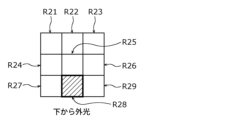
- FIG. 17G is a diagram showing a first example of the determination results of the incidence level of each of the nine divided regions when external light is incident from below.
- FIG. 17C is a diagram showing a first example of the determination results of the incidence level of each of the nine divided regions when external light is incident from the bottom left.
- FIG. 17D is a diagram showing a first example of the determination results of the
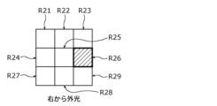
- FIG. 17H is a diagram showing a first example of the determination results of the incidence level of each of the nine divided regions when external light is incident from the right.
- FIG. 18A is a diagram showing a second example of the determination results of the incidence level of each of the nine divided regions when external light is incident from the upper left.
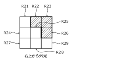
- FIG. 18B is a diagram showing a second example of the determination results of the incidence level of each of the nine divided regions when external light is incident from the upper right.
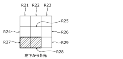
- FIG. 18C is a diagram showing a second example of the determination results of the incidence level of each of the nine divided regions when external light is incident from the bottom left.
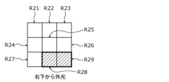
- FIG. 18D is a diagram showing a second example of the determination results of the incidence level of each of the nine divided regions when external light is incident from the bottom right.
- FIG. 18A is a diagram showing a second example of the determination results of the incidence level of each of the nine divided regions when external light is incident from the upper left.
- FIG. 18B is a diagram showing a second example of the
- FIG. 19G is a diagram showing a second example of the determination results of the incidence level of each of the nine divided regions when external light is incident from below.
- FIG. 19H is a diagram showing a second example of the determination results of the incidence level of each of the nine divided regions when external light is incident from the right.
- FIG. 20A is a diagram showing a fifth example of the determination results of the incidence level of each of the nine divided regions when external light is incident from the upper left.
- FIG. 20B is a diagram showing a fifth example of the determination results of the incidence level of each of the nine divided regions when external light is incident from the upper right.
- FIG. 20C is a diagram showing a fifth example of the determination results of the incidence level of each of the nine divided regions when external light is incident from the bottom left.
- FIG. 20A is a diagram showing a fifth example of the determination results of the incidence level of each of the nine divided regions when external light is incident from the upper left.
- FIG. 20B is a diagram showing a fifth example of the determination results
- FIG. 21F is a diagram showing a second example of the determination results of the incidence level of each of the nine divided regions when external light is incident from below.
- FIG. 21G is a diagram showing a second example of the determination results of the incidence level of each of the nine divided regions when external light is incident from the left.
- FIG. 21H is a diagram showing a second example of the determination results of the incidence level of each of the nine divided regions when external light is incident from the right.
- FIG. 22 is a diagram illustrating an example of first action information according to the second modification of the embodiment.
- FIG. 23 is a diagram illustrating an example of second countermeasure information according to the second modification of the embodiment.
- FIG. 24 is a diagram illustrating an example of the third action information according to the second modification of the embodiment.
- the number of pixels with high red pixel values varies greatly depending on whether external light is present or not.
- the inventors of the present application focused on this number of pixels with high red pixel values and discovered that this number of pixels can be used as an example of a method for determining the presence or absence of external light.
- the inventors of the present application then conducted extensive research into image processing methods and the like that can use, for example, the number of pixels with high red pixel values to notify users that a plaque area may have been erroneously detected due to external light entering the oral cavity, and devised the image processing methods and the like described below.
- the image processing method according to the fifth aspect is an image processing method according to any one of the first to fourth aspects, and the incidence level may be acquired based on the detection result of a detector that detects external light incident on the shooting area of the first RGB image.
- the image processing method according to the seventh aspect may be the image processing method according to the sixth aspect, in which the incidence level includes a first incidence level, the first red pixel count includes a first number of red pixels having the pixel value at each pixel value equal to or greater than the first pixel value, and the green pixel count having a green pixel value equal to or greater than the first pixel value includes a second number of green pixels having the pixel value at each pixel value equal to or greater than the first pixel value, and the image processing method may calculate the first incidence level based on a first accumulated value obtained by subtracting the second pixel count from the first pixel count at each pixel value equal to or greater than the first pixel value and accumulating the first subtraction value obtained by subtracting the second pixel number from the first pixel number, the first subtraction value being positive, and the display mode of the plaque detection result may be changed depending on whether the first incidence level is equal to or less than a first predetermined value.
- the presence or absence of external light is determined using the first incident level based on the first integrated value, and the display mode of the plaque detection result can be changed depending on the result of the determination of the presence or absence of external light.
- the image processing method according to the ninth aspect may be the image processing method according to the seventh aspect, in which the incidence level includes a second incidence level, and the second number of red pixels having a red pixel value equal to or greater than a second pixel value higher than the first pixel value includes a third number of red pixels having the pixel value at each pixel value equal to or greater than the second pixel value, and the image processing method may calculate the second incidence level based on a second integrated value obtained by subtracting the second pixel number from the third pixel number at each pixel value equal to or greater than the second pixel value, and integrating the second subtraction value obtained by subtracting the second pixel number from the third pixel number, the second subtraction value being positive, and the display mode of the plaque detection result may be changed depending on whether the second incidence level is equal to or less than a second predetermined value.
- the second integrated value it is possible to determine that there is external light even when external light is entering a localized area (for example, a localized area of a tooth is shiny). This makes it possible to reduce erroneous detections in which it is determined that there is no external light even when external light is entering a localized area.
- the image processing method according to the twelfth aspect may be the image processing method according to the sixth aspect, in which a V image is generated from V values obtained by HSV conversion of each pixel value of the first RGB image, and the incidence level is calculated based on an integrated value of the number of pixels whose V values are equal to or greater than the first pixel value.
- the image processing method according to the thirteenth aspect is an image processing method according to any one of the second to fourth aspects, and the predetermined value may be set according to the lighting environment of the space in which the first RGB image is captured.
- a predetermined value appropriate for each lighting environment is set, making it possible to accurately determine the presence or absence of external light even when the lighting environment changes.
- the image processing method according to the 19th aspect is an image processing method according to any one of the 16th to 18th aspects, in which the direction in which the external light is incident is determined based on the positional relationship of an area among the multiple areas in which the incidence level exceeds the predetermined value, and the countermeasure information may include information regarding the direction in which the external light is incident.
- the image processing system is an image processing system for displaying a plaque area based on an RGB image obtained by photographing the teeth and plaque that are undergoing a fluorescent reaction by irradiating the teeth with light including a wavelength range of blue light, and includes an acquisition unit that acquires the incidence level of external light incident on the photographed area of the RGB image, a plaque detection unit that performs plaque detection processing based on the RGB image, and a display control unit that changes the display mode of the plaque detection result depending on the incidence level of external light incident on the photographed area of the RGB image.
- the program according to the 21st aspect of the present disclosure is a program for causing a computer to execute an image processing method according to any one of the first to 19th aspects.
- each figure is a schematic diagram and is not necessarily an exact illustration. Therefore, for example, the scales of the figures do not necessarily match.
- the same reference numerals are used for substantially the same configurations, and duplicate explanations are omitted or simplified.
- the intraoral camera 10 has a toothbrush-like housing that can be handled with one hand, and the housing has a head portion 10a that is placed in the user's oral cavity when photographing the dentition, a handle portion 10b that is held by the user, and a neck portion 10c that connects the head portion 10a and the handle portion 10b.
- the imaging unit 21 is incorporated into the head portion 10a and the neck portion 10c.
- the imaging unit 21 has an image sensor (not shown) and a lens (not shown) arranged on its optical axis LA.
- the imaging element is a photographing device such as a CMOS (Complementary Metal Oxide Semiconductor) sensor or a CCD (Charge Coupled Device) element, and an image of the teeth is formed by a lens.
- the imaging element outputs a signal (image data) corresponding to the formed image to the outside.
- the dentition image photographed by the imaging element is an example of an RGB image.
- the dentition image may be an image of the side of the teeth, or an image of the occlusal surfaces of the teeth.
- the side of the teeth may be the inner (lingual) side or the outer (cheek) side.
- the photographing unit 21 may further have a light-blocking filter that blocks light of a color irradiated from the illumination unit and transmits fluorescence emitted by plaque in response to the light.
- the photographing unit 21 may have a blue light-blocking filter that blocks light components of blue wavelengths contained in light incident on the image sensor 14. When light including a wavelength range of blue light is irradiated onto teeth to detect plaque, if light including a wavelength range of blue light is strengthened to strengthen the excitation fluorescence of plaque, the entire RGB image will be blue-tinged.
- the intraoral camera 10 is also equipped with a number of first to fourth light emitting diodes (LEDs) 23A to 23D as an illumination unit (illumination device) that irradiates light onto the teeth to be photographed during photography.
- the first to fourth LEDs 23A to 23D irradiate plaque with light of a color (e.g., single-color light) that causes the plaque to fluoresce when irradiated with the plaque.
- the first to fourth LEDs 23A to 23D are, for example, blue LEDs that irradiate blue light including a wavelength with a peak at 405 nm. Note that the first to fourth LEDs 23A to 23D are not limited to blue LEDs, and may be any light source that irradiates light including the wavelength range of blue light.
- the intraoral camera system is generally configured such that the imaging unit 21 captures the fluorescence emitted by plaque in response to light from the illumination unit 23.
- the intraoral camera system includes an intraoral camera 10 and a mobile terminal 50.
- the intraoral camera system is an example of an image processing system.
- the intraoral camera system is configured to be able to notify the user that, when plaque regions are detected based on an image (RGB image) captured by the intraoral camera 10 while external light is entering the oral cavity, the plaque regions may have been erroneously detected due to external light entering the oral cavity.
- the notification may be to display information indicating the possibility of erroneous detection on the image (for example, see FIG. 9 described below), or to output the possibility of erroneous detection by sound, light, etc.
- external light is light other than the light emitted by the illumination unit 23, and examples include illumination light, sunlight, etc. External light may include, for example, light of the same color as the fluorescence emitted by plaque.
- the hardware unit 20 is a physical element of the intraoral camera 10, and includes an imaging unit 21, a sensor unit 22, an illumination unit 23, and an operation unit 24.
- the photographing unit 21 generates image data by photographing the teeth in the user's mouth.
- the photographing unit 21 receives a control signal from the camera control unit 31, performs operations such as photographing in accordance with the received control signal, and outputs moving or still image data obtained by photographing to the image processing unit 32.
- the photographing unit 21 has the above-mentioned image sensor, light-shielding filter, and lens.
- the photographing unit 21 generates image data based on light that has passed through the light-shielding filter. Furthermore, the image data is a tooth row image showing multiple teeth, but it is sufficient that the tooth row image shows at least one tooth.
- Each of the first to fourth LEDs 23A to 23D is configured so that at least the dimming can be controlled.
- Each of the first to fourth LEDs 23A to 23D may be configured so that the dimming and color can be controlled.
- the first to fourth LEDs 23A to 23D are arranged to surround the image capture unit 21.
- the signal processing unit 30 has various functional components realized by a CPU (Central Processing Unit) or MPU (Micro Processor Unit) that execute various processes described below, and a memory unit 35 such as a ROM (Read Only Memory) or RAM (Random Access Memory) that stores programs for causing each functional component to execute various processes.
- the signal processing unit 30 has a camera control unit 31, an image processing unit 32, a control unit 33, a lighting control unit 34, and a memory unit 35.
- the camera control unit 31 is mounted, for example, on the handle unit 10b of the intraoral camera 10, and controls the image capture unit 21.
- the camera control unit 31 controls at least one of the aperture and the shutter speed of the image capture unit 21 in response to a control signal from the image processing unit 32, for example.
- the image processing unit 32 is mounted, for example, on the handle unit 10b of the intraoral camera 10, acquires the dentition image (image data) captured by the imaging unit 21, performs image processing on the acquired dentition image, and outputs the dentition image after the image processing to the camera control unit 31 and the control unit 33.
- the image processing unit 32 may also output the dentition image after the image processing to the memory unit 35, and store the dentition image after the image processing in the memory unit 35.
- the dentition image output from the image processing unit 32 may be transmitted to the mobile terminal 50 via the communication unit 40, and the transmitted dentition image may be displayed on the touch screen 54 of the mobile terminal 50. This allows the dentition image to be presented to the user.
- the control unit 33 detects the area of plaque based on the image data that has been image-processed by the image processing unit 32.
- the control unit 33 may input the image data and identify the area of plaque that appears in the image data using a machine learning model that has been trained to output the area of plaque that appears in the image data.
- the memory unit 35 stores images of the dentition (image data) captured by the imaging unit 21.
- the memory unit 35 is realized, for example, by a semiconductor memory such as a ROM or RAM, but is not limited to this.
- the mobile terminal 50 displays the plaque area based on an RGB image of the teeth and plaque that are fluorescently reacting when light including the wavelength range of blue light is irradiated onto the teeth.
- the mobile terminal 50 also functions as a user interface for the intraoral camera system.
- the mobile terminal 50 includes an acquisition unit 51, a control unit 52, a display control unit 53, and a touch screen 54.
- the mobile terminal 50 includes a processor and a memory.
- the memory is a ROM, a RAM, or the like, and can store a program executed by the processor.
- the acquisition unit 51, the control unit 52, and the display control unit 53 are realized by a processor that executes a program stored in the memory.
- the mobile terminal 50 may be realized, for example, by a smartphone or tablet terminal capable of wireless communication.
- the acquisition unit 51 acquires an RGB image from the intraoral camera 10.
- the acquisition unit 51 is, for example, a wireless communication module that performs wireless communication.
- the control unit 52 subtracts the second number of pixels having the first pixel value from the first number of pixels having the pixel value for each of the pixel values equal to or greater than the first pixel value, accumulates the first subtraction value obtained by subtracting the second number of pixels from the first number of pixels, which is a positive first subtraction value, and calculates a first incidence level based on a first accumulated value obtained by accumulating the first subtraction values.
- the control unit 52 may, for example, calculate a value obtained by dividing the first accumulated value by the total number of pixels as the first incidence level. Note that calculating the incidence level is an example of obtaining the incidence level.
- the control unit 52 may determine whether or not external light is incident by evaluating the number of pixels whose green pixel value is smaller than the red pixel value. In this case, the control unit 52 may determine whether or not external light is incident based on a first red pixel number including a first pixel number of red pixels having a pixel value equal to or greater than the first pixel value, and a green pixel number including a second pixel number of green pixels having a pixel value (green pixel value) equal to or less than a fourth pixel value lower than the first pixel value.
- control unit 52 may subtract the second pixel number from the first pixel number, and calculate the first incidence level based on the first subtraction value if the first subtraction value obtained by subtracting the second pixel number from the first pixel number is positive. For example, the control unit 52 may calculate a value obtained by dividing the first subtraction value by the total number of pixels as the first incidence level.
- first red pixel number is not limited to the above, and may be the number of pixels whose red pixel value is relatively larger than the green pixel value, and the green pixel number may be the number of pixels whose green pixel value is relatively larger than the red pixel value.
- the third pixel value and the third predetermined value are appropriately set according to the lighting environment of the space in which the intraoral camera 10 is used.
- the third pixel value may be 250.
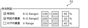
- Area A in Figure 4 is an area where almost all of the circles are plotted, indicating that there is no external light. From this, it is possible to determine with high accuracy that there is no external light by determining that there is no external light when the first incident level is equal to or lower than a threshold value r2 (e.g., approximately 0.18). Similarly, it is possible to determine with high accuracy that there is no external light by determining that there is no external light when the third incident level is equal to or lower than a threshold value v2 (e.g., approximately 0.24). In this case, since there is no external light, plaque detection processing is executed.
- a threshold value r2 e.g., approximately 0.18
- v2 e.g., approximately 0.24
- Area C in Figure 4 is an area where all circles indicating the presence of external light are plotted. From this, it is possible to determine with high accuracy that there is external light by determining that there is external light when the first incident level is equal to or greater than a threshold value r1 (e.g., 0.45). Similarly, it is possible to determine with high accuracy that there is external light by determining that there is external light when the third incident level is equal to or greater than a threshold value v1 (e.g., 0.45). In this case, since there is a high possibility that the plaque area will be erroneously detected due to external light, the plaque detection process is not executed.
- a threshold value r1 e.g. 0.45
- v1 e.g. 0.45
- Threshold value r1 is an example of a first predetermined value
- threshold value r2 is an example of a fourth predetermined value
- threshold value v1 is an example of a third predetermined value
- threshold value v2 is an example of a fifth predetermined value.
- Area B in Figure 4 is an area where circles with and without external light are plotted together.
- the plaque detection process is executed, but there is a possibility that the plaque area may be erroneously detected due to external light. Therefore, the display mode of the plaque detection result is made different when the area where at least one of the first incidence level and the third incidence level is plotted is area B from when it is area A. Specifically, when it is area B, the plaque detection result is displayed in a display mode that informs the user that the plaque area may have been erroneously detected.
- control unit 52 uses the first method, for example, if the value (number of pixels) obtained by subtracting the number of green pixels with pixel value 130 from the number of red pixels with pixel value 130 is positive, the control unit 52 uses the value itself in the calculation, and if the value is negative, sets the value to zero. Next, the control unit 52 performs similar processing for each pixel value between 131 and 255 inclusive. For example, if there are 100 red pixels with a pixel value of 130 and 50 green pixels with a pixel value of 130, the value in pixel value 130 will be 50. Also, for example, if there are 100 red pixels with a pixel value of 131 and 150 green pixels with a pixel value of 131, the value in pixel value 130 will be zero.
- the control unit 52 uses a value (number of pixels) obtained by subtracting the number of pixels whose green pixel value is 129 or less (i.e., the fourth pixel value is 129) from the number of pixels whose red pixel value is 130 or more (i.e., the first pixel value is 130) from the number of pixels whose green pixel value is 129 or less (i.e., the fourth pixel value is 129). For example, if there are 100 pixels whose red pixel value is 130 or more and 50 pixels whose green pixel value is 129 or less, the value is 50. Also, if there are 50 pixels whose red pixel value is 130 or more and 100 pixels whose green pixel value is 129 or less, the value is zero.
- control unit 52 determines that there is external light if the following formula 1 is satisfied using a first accumulated value obtained by accumulating the positive value.
- the first accumulated value of the two pixel values 130 and 131 is 50 (50 + 0).
- the second method above if there are 100 pixels with a red pixel value of 130 or more and 50 pixels with a green pixel value of 129 or less, the first accumulated value will be 50 (100 - 50).
- Area D in Figure 5 is an area where circles with and without external light are plotted together. In this case, the plaque detection process is executed, but there is a possibility that the plaque area may be erroneously detected due to external light. Therefore, when the area where the second incidence level and the third incidence level are plotted is area D, the plaque detection result is displayed in a display manner that notifies the user that the plaque area may have been erroneously detected.
- the pixel value for counting the number of pixels may be changed according to the lighting environment of the space.
- the pixel values (the above-mentioned first pixel value to third pixel value) may be input by the user, for example.
- the touch screen 54 functions as an input device and an output device, and is configured to be capable of displaying, for example, an image of a dentition.
- the touch screen 54 may have, for example, a display unit such as a liquid crystal display panel, and a touch panel disposed over the display unit.
- FIG. 7 is a diagram showing a captured image with and without external light in this embodiment, and a display example of a plaque detection result.
- FIG. 7 shows a captured image with and without external light, and a display example of a plaque detection result.
- the captured image is an RGB image obtained by the intraoral camera 10 capturing an image of the teeth and gums in the oral cavity.
- the display of the plaque detection result is an image in which the plaque area detected after the control unit 52 executes the plaque detection process is highlighted, and is an image displayed on the touch screen 54.
- the user can take images of the inside of their own oral cavity with the intraoral camera 10 and check the condition of the oral cavity displayed on the mobile terminal 50. This allows the user to easily check the health condition of their own teeth, etc.
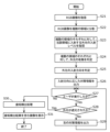
- the acquisition unit 51 acquires an RGB image transmitted from the intraoral camera 10 (S11).
- the RGB image is an image obtained by the intraoral camera 10 photographing the teeth and plaque that are undergoing a fluorescent reaction by irradiating the teeth with light that includes the wavelength range of blue light.
- the control unit 52 acquires the incident level of external light based on the acquired RGB image (S12).
- the control unit 52 may calculate the incident level, for example, by dividing at least one of the first to third integrated values based on the RGB image by the total number of pixels. Note that the incident level includes at least one of the first to third incident levels.
- FIG. 9 is a diagram showing an example of a display with and without external light according to this embodiment.
- FIG. 9 shows a dentition image. Note that for convenience, the display of plaque detection results (e.g., highlighted display) is omitted in (a) and (b) of FIG. 9.
- step S15 is an image displayed in step S15, in which first information (a circle with diagonal hatching in (a) in FIG. 9) indicating that external light is entering (or there is a possibility that external light is entering) is displayed superimposed on the image including the plaque detection result.
- the first information is displayed, for example, superimposed on an area different from the tooth area and the plaque area (e.g., the highlighted area). Note that if the incidence level is not below a predetermined value, the control unit 52 may prohibit the display of the plaque detection result or the execution of the plaque detection process.
- control unit 52 displays the first information when there is external light, and displays the second information or displays only the plaque detection result when there is no external light. In this way, the control unit 52 changes the display mode of the plaque detection result depending on the presence or absence of external light.
- the control unit 52 further determines whether or not at least one of the following is satisfied: the first incidence level is equal to or less than a first predetermined value (e.g., threshold value r1 shown in FIG. 4) and equal to or more than a fourth predetermined value (e.g., threshold value r2 shown in FIG. 4) lower than the first predetermined value, and the third incidence level is equal to or less than a third predetermined value (e.g., threshold value v1 shown in FIG. 4) and equal to or more than a fifth predetermined value (e.g., threshold value v2 shown in FIG. 4) lower than the third predetermined value.
- a first predetermined value e.g., threshold value r1 shown in FIG. 4
- a fourth predetermined value e.g., threshold value r2 shown in FIG.
- control unit 52 If it is determined that the above conditions are satisfied, the control unit 52 outputs the determination result to the display control unit 53, thereby superimposing information encouraging light blocking on the image displaying the plaque detection result.
- each predetermined value may be set according to the lighting environment under which the RGB image is captured.
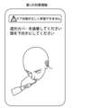
- FIG. 10 shows an example of a display encouraging the user to block light in accordance with this embodiment.
- the control unit 52 may issue a notification to prompt the user to block light to prevent external light from entering the oral cavity. Furthermore, instead of a display encouraging the user to block light, the control unit 52 may display a display encouraging the user to dim or turn off the lights. Note that the display encouraging the user to block light may include, for example, a display encouraging the user to close the curtains. Note that the display encouraging the user to block light is displayed, for example, superimposed on an area different from the tooth area and plaque area (for example, a highlighted area).
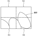
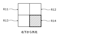
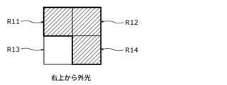
- the control unit 52 may divide the RGB image into a number of regions (four regions R1 to R4 in the example of FIG. 11), obtain the incident level of external light entering each of the divided regions, and vary the display mode of the plaque detection result depending on the determination result of whether the incident level of each of the multiple regions is below a predetermined value. For example, the control unit 52 may determine that external light is present when the incident level of at least one of the multiple regions is not below a predetermined value. The control unit 52 may perform a determination of Equation 1 and Equation 3 shown in the embodiment for each of the multiple regions, and determine that external light is present when at least one region satisfies at least one of Equation 1 and Equation 3.
- the first pixel value is set to, for example, a value larger than the first pixel value in the embodiment. For example, the narrower the area on the image for determining the incidence level, the larger the first pixel value may be set.
- the second pixel value is set to, for example, a value larger than the second pixel value in the embodiment.
- the first pixel value is, for example, 0.8
- the second pixel value is, for example, 0.5, but is not limited to this.
- the intraoral camera 10 stores a table that associates the sizes of multiple areas with the first pixel value and the second pixel value, and the first pixel value and the second pixel value may be automatically set based on the table. The sizes of the multiple areas may also be set, for example, by the user.
- the number of divisions is not particularly limited as long as it is two or more.
- the size, shape, etc. of each region may be the same or different.
- FIG. 14 is a flowchart showing the operation (image processing method) of the mobile terminal 50 according to this modified example.
- the intraoral camera system according to this modified example differs from the intraoral camera system according to the embodiment in that it divides an RGB image into multiple regions and presents information encouraging the user to take measures against external light based on the level of external light incident on each of the multiple regions (e.g., the presence or absence of external light).
- the following description will use the reference symbols of the intraoral camera system according to the embodiment.
- the acquisition unit 51 acquires an RGB image transmitted from the intraoral camera 10 (S21).
- the RGB image is an image obtained by the intraoral camera 10 photographing the teeth and plaque that are undergoing a fluorescent reaction by irradiating the teeth with light that includes the wavelength range of blue light.
- the multiple regions are quadrangular regions, but the shape is not limited to a quadrangular shape and may be any other shape, such as a circle, a triangle, or a polygon with pentagons or more sides.
- a single RGB image may contain a mixture of regions of multiple shapes. The areas of the multiple regions may be equal, or the area of at least one region may be different from the areas of the other regions.
- the quadrangles may be square or rectangular.
- the control unit 52 acquires the incidence level of external light incident on each of the multiple regions (S23). For example, the control unit 52 calculates at least one integrated value of the first to third integrated values for each of the multiple regions, and divides the calculated at least one integrated value by the total number of pixels in the region to calculate the incidence level. One incidence level is calculated for one region. Note that the incidence levels of each of the multiple regions are not limited to being acquired by calculation, and may be acquired from an external device via the acquisition unit 51, for example.
- the control unit 52 determines the presence or absence of external light for each of the multiple regions (S24).
- the control unit 52 determines the presence or absence of external light for each of the multiple regions based on the incidence level of the region.
- the control unit 52 may determine the presence or absence of external light for each of the multiple regions using the above (Equation 1) or (Equation 2).
- the first integrated value shown in (Equation 1) and the second integrated value shown in (Equation 2) are values in the region, and the total number of pixels is the total number of pixels in the region.
- the control unit 52 may determine whether or not external light is incident on the RGB image based on the determination result of step S24, and if it determines that external light is incident on the RGB image, may execute the processing from step S25 onwards, and if it determines that external light is not incident on the RGB image, may end the processing.
- the control unit 52 may determine that external light is incident on the RGB image if it determines in step S24 that external light is present in at least one of the multiple regions.
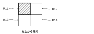
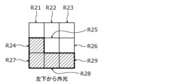
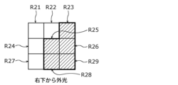
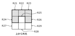
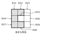
- the control unit 52 determines that external light is entering from the upper left of the RGB image, and when it is determined that external light is present only in regions R22 and R23, it determines that external light is entering from the upper right of the RGB image. Also, as shown in Figures 18G and 18H, when it is determined that external light is present only in regions R27 and R28, the control unit 52 determines that external light is entering from the lower left of the RGB image, and when it is determined that external light is present only in regions R28 and R29, it determines that external light is entering from the lower right of the RGB image.
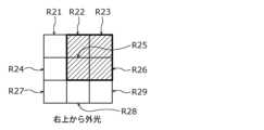
- FIGS. 19A to 19D show cases where it is determined that there is external light in three areas arranged in an L shape
- FIGS. 19E to 19H show cases where it is determined that there is external light in three areas that are connected in a straight line.
- Figs. 22 to 24 are diagrams showing examples of each piece of countermeasure information according to this modified example.
- the second countermeasure information shown in Fig. 23 includes countermeasures that impose a greater execution burden on the user than the first countermeasure information shown in Fig. 22, and the third countermeasure information shown in Fig. 24 includes, but is not limited to, countermeasures that impose a greater execution burden on the user than the second countermeasure information shown in Fig. 23.
- control unit 52 may decide to output the second countermeasure information, for example, when it is determined that there is external light in two of the four regions into which the RGB image is divided (see FIGS. 15E to 15H), or when it is determined that there is external light in three or four of the nine regions into which the RGB image is divided (see FIGS. 19A to 20H).
- FIG. 24 shows an example of the display of third countermeasure information, which includes measures such as turning off the lights in the room or moving the location where the intraoral camera is used.
- the first and second countermeasure information are measures that can be implemented without the user having to move, but the third countermeasure information includes measures in which the user has to move or control a device external to the intraoral camera system, and includes measures that impose a greater burden on the user than the first and second countermeasure information.
- the control unit 52 may also determine the third countermeasure information, for example, when it is determined that there is external light in one or two of the four regions into which the RGB image is divided, or when it is determined that there is external light in one to four of the nine regions into which the RGB image is divided, and the determination that there is external light is the second or subsequent time.
- the control unit 52 may determine the third countermeasure information, for example, when it has output the second countermeasure information and it is determined that there is external light despite the implementation of that countermeasure. In this way, the control unit 52 may determine the countermeasure information depending on whether it is determined that there is external light after outputting the countermeasure information.
- the mobile device 50 may determine and display countermeasure information according to at least one of the number of areas where the incident level exceeds a predetermined value and the positions (positions on the RGB image) of the areas where the incident level exceeds a predetermined value among the multiple areas.
- the control unit 52 determines whether the user has implemented the measure indicated by the outputted measure information (S27).
- the control unit 52 functions as a determination unit that determines whether the user has responded to the outputted measure information.
- the control unit 52 may determine that the user has implemented the measure information, for example, when the touch screen 54 receives a user operation indicating that the measure included in the measure information has been implemented, when information based on an image of the user captured by an external imaging device and indicating that the measure indicated by the measure information has been implemented is acquired via the acquisition unit 51, or when a predetermined time has elapsed since the output of the measure information.
- control unit 52 determines in step S24 executed again that there is no external light in each of the multiple regions, it determines Yes in step S28, and if it determines that there is external light in at least one of the multiple regions, it determines No in step S28.
- the control unit 52 If the external light is not blocked (No in S28), the control unit 52 outputs countermeasure information different from the countermeasure information output in step S26 (S29).
- the different countermeasure information is, for example, information according to at least one of the number of areas among the multiple areas in which the incident level after the countermeasure exceeds a predetermined value and the position of the area among the multiple areas.
- control unit 52 may output the first countermeasure information in step S26, it may output the second countermeasure information in step S29, and if the control unit 52 has output the second countermeasure information in step S26, it may output the third countermeasure information in step S29.
- the control unit 52 may, for example, determine and display the second countermeasure information that is different from the first countermeasure information based on the incidence level after the countermeasure is implemented for each of the multiple regions.
- the method of determining the other countermeasure information is not limited to the above, and other methods may be used.
- the other countermeasure information may be determined based on a table in which the output countermeasure information and at least one of the number and positions of areas determined to have external light before and after the output of the countermeasure information are associated with the other countermeasure information.
- step S29 is executed, or if step S27 returns No, processing returns to step S27 and continues.
- control unit 52 executes the processing from step S30 onwards.
- step S30 is similar to the process shown in step S13 in FIG. 8, and the process shown in step S31 is similar to the process shown in step S16 in FIG. 8, so the description will be omitted.
- the intraoral camera system according to one or more aspects has been described based on the embodiment, the present disclosure is not limited to the embodiment. As long as it does not deviate from the gist of the present disclosure, various modifications conceived by a person skilled in the art to the present embodiment and forms constructed by combining components in different embodiments may also be included in the present disclosure.
- the intraoral camera 10 in the above-described embodiments may also be mounted on, for example, an oral irrigator.
- the manner of notification is not limited to a display, and may be, for example, by emitting a sound or emitting light (e.g., a warning light).
- the mobile terminal 50 may be equipped with a sound output device such as a speaker or a light-emitting device such as an LED.
- control unit 52 may determine the first countermeasure information when the incidence level is less than the first level, determine the second countermeasure information when the incidence level is equal to or greater than the first level and less than a second level higher than the first level, and determine the third countermeasure information when the incidence level is equal to or greater than the second level.
- the mobile terminal 50 according to the above embodiment has been described as an example in which the display mode of the plaque detection result is changed according to the incidence level of external light incident on the shooting area of the RGB image, and countermeasure information for suppressing the influence of external light according to the incidence level is displayed.
- the present disclosure is not limited to this, and may be realized as an image processing method that does not change the display mode of the plaque detection result, but displays countermeasure information for suppressing the influence of external light according to the incidence level.
- the present disclosure may be realized as an image processing method for displaying a plaque area based on an RGB image obtained by photographing teeth and plaque that are fluorescently reacting by irradiating the teeth with light including a wavelength range of blue light, and the image processing method obtains the incidence level of external light incident on the shooting area of the RGB image and displays countermeasure information for suppressing the influence of external light according to the incidence level. This makes it possible to effectively suppress external light entering the oral cavity.
- an RGB image reflecting the result of the determination of the presence or absence of external light may also be displayed.
- the RGB image may be displayed as an image that is flipped left to right. This makes the incident direction of the external light in the image seen by the user match the actual incident direction, making it easier for the user to intuitively grasp the incident direction.
- step S14 shown in FIG. 8 may be executed between steps S12 and S13. If the answer is No at step S14, external light is incident, and so the plaque detection processing of step S13 may be omitted. Some of the steps may also be executed simultaneously (in parallel) with other steps, or some of the steps may not be executed.
- the division of functional blocks in the block diagram is one example, and multiple functional blocks may be realized as one functional block, one functional block may be divided into multiple blocks, or some functions may be transferred to other functional blocks. Furthermore, the functions of multiple functional blocks having similar functions may be processed in parallel or in a time-shared manner by a single piece of hardware or software.
- the mobile terminal 50 may be realized as a single device, or may be realized by multiple devices.
- the components of the mobile terminal 50 may be distributed in any manner among the multiple devices.
- at least some of the functions of the mobile terminal 50 may be realized by the intraoral camera 10 (e.g., the signal processing unit 30).
- the communication method between the multiple devices is not particularly limited, and may be wireless communication or wired communication. Furthermore, wireless communication and wired communication may be combined between the devices.
- each component described in the above embodiments may be realized as software, or may be realized as an LSI, which is typically an integrated circuit. These may be individually integrated into one chip, or may be integrated into one chip to include some or all of them.
- LSI is used, but depending on the degree of integration, it may be called IC, system LSI, super LSI, or ultra LSI.
- the method of integration is not limited to LSI, and may be realized with a dedicated circuit (a general-purpose circuit that executes a dedicated program) or a general-purpose processor. After LSI manufacture, a programmable FPGA (Field Programmable Gate Array) or a reconfigurable processor that can reconfigure the connection or settings of the circuit cells inside the LSI may be used.
- a programmable FPGA Field Programmable Gate Array
- reconfigurable processor that can reconfigure the connection or settings of the circuit cells inside the LSI may be used.
- an integrated circuit technology that replaces LSI appears due to advances in semiconductor technology or
- a system LSI is an ultra-multifunctional LSI manufactured by integrating multiple processing units on a single chip, and is specifically a computer system that includes a microprocessor, ROM, RAM, etc. Computer programs are stored in the ROM. The system LSI achieves its functions when the microprocessor operates according to the computer program.
- Another aspect of the present disclosure may be a computer program that causes a computer to execute each of the characteristic steps included in the image processing method shown in FIG. 8 or FIG. 14.
- This disclosure can be applied to intraoral camera systems.
Landscapes
- Health & Medical Sciences (AREA)
- Life Sciences & Earth Sciences (AREA)
- Engineering & Computer Science (AREA)
- Multimedia (AREA)
- Signal Processing (AREA)
- Biomedical Technology (AREA)
- Animal Behavior & Ethology (AREA)
- Veterinary Medicine (AREA)
- Public Health (AREA)
- General Health & Medical Sciences (AREA)
- Biophysics (AREA)
- Surgery (AREA)
- Radiology & Medical Imaging (AREA)
- Heart & Thoracic Surgery (AREA)
- Medical Informatics (AREA)
- Molecular Biology (AREA)
- Physics & Mathematics (AREA)
- Pathology (AREA)
- Optics & Photonics (AREA)
- Nuclear Medicine, Radiotherapy & Molecular Imaging (AREA)
- Oral & Maxillofacial Surgery (AREA)
- Dentistry (AREA)
- Epidemiology (AREA)
- Endoscopes (AREA)
Priority Applications (2)
| Application Number | Priority Date | Filing Date | Title |
|---|---|---|---|
| JP2025551479A JPWO2025079536A1 (https=) | 2023-10-13 | 2024-10-04 | |
| CN202480005907.9A CN120417823A (zh) | 2023-10-13 | 2024-10-04 | 图像处理方法、图像处理系统以及程序 |
Applications Claiming Priority (2)
| Application Number | Priority Date | Filing Date | Title |
|---|---|---|---|
| JP2023177750 | 2023-10-13 | ||
| JP2023-177750 | 2023-10-13 |
Publications (1)
| Publication Number | Publication Date |
|---|---|
| WO2025079536A1 true WO2025079536A1 (ja) | 2025-04-17 |
Family
ID=95395852
Family Applications (1)
| Application Number | Title | Priority Date | Filing Date |
|---|---|---|---|
| PCT/JP2024/035690 Pending WO2025079536A1 (ja) | 2023-10-13 | 2024-10-04 | 画像処理方法、画像処理システム及びプログラム |
Country Status (3)
| Country | Link |
|---|---|
| JP (1) | JPWO2025079536A1 (https=) |
| CN (1) | CN120417823A (https=) |
| WO (1) | WO2025079536A1 (https=) |
Citations (4)
| Publication number | Priority date | Publication date | Assignee | Title |
|---|---|---|---|---|
| JP2004237081A (ja) * | 2003-01-14 | 2004-08-26 | Morita Mfg Co Ltd | 診断用撮影器 |
| JP2007151782A (ja) * | 2005-12-05 | 2007-06-21 | Morita Mfg Co Ltd | 口腔観察器 |
| JP2008244794A (ja) | 2007-03-27 | 2008-10-09 | Olympus Corp | 画像処理装置、及び、画像処理方法 |
| JP2021124507A (ja) * | 2020-01-31 | 2021-08-30 | メディット コーポレーション | 外部光干渉除去方法 |
-
2024
- 2024-10-04 JP JP2025551479A patent/JPWO2025079536A1/ja active Pending
- 2024-10-04 CN CN202480005907.9A patent/CN120417823A/zh active Pending
- 2024-10-04 WO PCT/JP2024/035690 patent/WO2025079536A1/ja active Pending
Patent Citations (4)
| Publication number | Priority date | Publication date | Assignee | Title |
|---|---|---|---|---|
| JP2004237081A (ja) * | 2003-01-14 | 2004-08-26 | Morita Mfg Co Ltd | 診断用撮影器 |
| JP2007151782A (ja) * | 2005-12-05 | 2007-06-21 | Morita Mfg Co Ltd | 口腔観察器 |
| JP2008244794A (ja) | 2007-03-27 | 2008-10-09 | Olympus Corp | 画像処理装置、及び、画像処理方法 |
| JP2021124507A (ja) * | 2020-01-31 | 2021-08-30 | メディット コーポレーション | 外部光干渉除去方法 |
Also Published As
| Publication number | Publication date |
|---|---|
| JPWO2025079536A1 (https=) | 2025-04-17 |
| CN120417823A (zh) | 2025-08-01 |
Similar Documents
| Publication | Publication Date | Title |
|---|---|---|
| EP2992805B1 (en) | Electronic endoscope system | |
| CN108697307A (zh) | 计算系统 | |
| EP3270587A1 (en) | Image processing device, image processing method, and program | |
| JP2008182360A (ja) | 皮膚領域検出撮像装置 | |
| JPWO2015029537A1 (ja) | 器官画像撮影装置 | |
| EP4620433A1 (en) | Image processing method, image processing device, and program | |
| KR101774748B1 (ko) | 휴대폰을 이용한 자외선 영상 촬영장치 | |
| JPWO2018038269A1 (ja) | 電子内視鏡用プロセッサ及び電子内視鏡システム | |
| JP2011182993A (ja) | 歯垢検知装置 | |
| CN107409200A (zh) | 图像处理装置、图像处理方法和程序 | |
| CN105934941B (zh) | 摄像装置、视频信号处理方法以及存储介质 | |
| US8570433B1 (en) | Coloration artifact reduction | |
| CN108886563B (zh) | 图像处理方法、图像处理装置、便携式多功能设备 | |
| CN107427264A (zh) | 摄像装置、图像处理装置和图像处理方法 | |
| JPWO2019155816A1 (ja) | 内視鏡システム | |
| WO2025079536A1 (ja) | 画像処理方法、画像処理システム及びプログラム | |
| JP7784630B2 (ja) | 歯垢検出装置、歯垢検出方法及びプログラム | |
| CN114283107A (zh) | 口腔检测方法、口腔检测装置以及计算机可读存储介质 | |
| US20160242678A1 (en) | Organ image photographing apparatus | |
| JP6533335B2 (ja) | ホワイトバランス調整装置及びその作動方法並びに作動プログラム | |
| CN109076199B (zh) | 白平衡调整装置及其工作方法和非临时性的计算机可读介质 | |
| WO2025079525A1 (ja) | 画像処理方法、画像処理装置及びプログラム | |
| WO2025173550A1 (ja) | 情報処理装置、情報処理方法及びプログラム | |
| WO2025173551A1 (ja) | 情報処理装置、情報処理方法及びプログラム | |
| JP4831962B2 (ja) | 撮影装置 |
Legal Events
| Date | Code | Title | Description |
|---|---|---|---|
| 121 | Ep: the epo has been informed by wipo that ep was designated in this application |
Ref document number: 24877132 Country of ref document: EP Kind code of ref document: A1 |
|
| WWE | Wipo information: entry into national phase |
Ref document number: 202480005907.9 Country of ref document: CN |
|
| ENP | Entry into the national phase |
Ref document number: 2025551479 Country of ref document: JP Kind code of ref document: A |
|
| WWE | Wipo information: entry into national phase |
Ref document number: 2025551479 Country of ref document: JP |
|
| WWP | Wipo information: published in national office |
Ref document number: 202480005907.9 Country of ref document: CN |