WO2025075271A1 - 차량용 기계식 압축기 토크 연산 방법 - Google Patents
차량용 기계식 압축기 토크 연산 방법 Download PDFInfo
- Publication number
- WO2025075271A1 WO2025075271A1 PCT/KR2024/009246 KR2024009246W WO2025075271A1 WO 2025075271 A1 WO2025075271 A1 WO 2025075271A1 KR 2024009246 W KR2024009246 W KR 2024009246W WO 2025075271 A1 WO2025075271 A1 WO 2025075271A1
- Authority
- WO
- WIPO (PCT)
- Prior art keywords
- vehicle
- mechanical compressor
- torque
- calculating
- sensor data
- Prior art date
- Legal status (The legal status is an assumption and is not a legal conclusion. Google has not performed a legal analysis and makes no representation as to the accuracy of the status listed.)
- Pending
Links
Images


Classifications
-
- B—PERFORMING OPERATIONS; TRANSPORTING
- B60—VEHICLES IN GENERAL
- B60H—ARRANGEMENTS OF HEATING, COOLING, VENTILATING OR OTHER AIR-TREATING DEVICES SPECIALLY ADAPTED FOR PASSENGER OR GOODS SPACES OF VEHICLES
- B60H1/00—Heating, cooling or ventilating devices
- B60H1/32—Cooling devices
- B60H1/3204—Cooling devices using compression
- B60H1/3205—Control means therefor
-
- B—PERFORMING OPERATIONS; TRANSPORTING
- B60—VEHICLES IN GENERAL
- B60H—ARRANGEMENTS OF HEATING, COOLING, VENTILATING OR OTHER AIR-TREATING DEVICES SPECIALLY ADAPTED FOR PASSENGER OR GOODS SPACES OF VEHICLES
- B60H1/00—Heating, cooling or ventilating devices
- B60H1/32—Cooling devices
-
- F—MECHANICAL ENGINEERING; LIGHTING; HEATING; WEAPONS; BLASTING
- F04—POSITIVE - DISPLACEMENT MACHINES FOR LIQUIDS; PUMPS FOR LIQUIDS OR ELASTIC FLUIDS
- F04B—POSITIVE-DISPLACEMENT MACHINES FOR LIQUIDS; PUMPS
- F04B27/00—Multi-cylinder pumps specially adapted for elastic fluids and characterised by number or arrangement of cylinders
- F04B27/08—Multi-cylinder pumps specially adapted for elastic fluids and characterised by number or arrangement of cylinders having cylinders coaxial with, or parallel or inclined to, main shaft axis
- F04B27/14—Control
- F04B27/16—Control of pumps with stationary cylinders
- F04B27/18—Control of pumps with stationary cylinders by varying the relative positions of a swash plate and a cylinder block
-
- F—MECHANICAL ENGINEERING; LIGHTING; HEATING; WEAPONS; BLASTING
- F04—POSITIVE - DISPLACEMENT MACHINES FOR LIQUIDS; PUMPS FOR LIQUIDS OR ELASTIC FLUIDS
- F04B—POSITIVE-DISPLACEMENT MACHINES FOR LIQUIDS; PUMPS
- F04B27/00—Multi-cylinder pumps specially adapted for elastic fluids and characterised by number or arrangement of cylinders
- F04B27/08—Multi-cylinder pumps specially adapted for elastic fluids and characterised by number or arrangement of cylinders having cylinders coaxial with, or parallel or inclined to, main shaft axis
- F04B27/14—Control
- F04B27/16—Control of pumps with stationary cylinders
- F04B27/18—Control of pumps with stationary cylinders by varying the relative positions of a swash plate and a cylinder block
- F04B27/1804—Controlled by crankcase pressure
-
- G—PHYSICS
- G06—COMPUTING OR CALCULATING; COUNTING
- G06N—COMPUTING ARRANGEMENTS BASED ON SPECIFIC COMPUTATIONAL MODELS
- G06N3/00—Computing arrangements based on biological models
- G06N3/02—Neural networks
-
- G—PHYSICS
- G06—COMPUTING OR CALCULATING; COUNTING
- G06V—IMAGE OR VIDEO RECOGNITION OR UNDERSTANDING
- G06V10/00—Arrangements for image or video recognition or understanding
- G06V10/70—Arrangements for image or video recognition or understanding using pattern recognition or machine learning
- G06V10/82—Arrangements for image or video recognition or understanding using pattern recognition or machine learning using neural networks
-
- B—PERFORMING OPERATIONS; TRANSPORTING
- B60—VEHICLES IN GENERAL
- B60H—ARRANGEMENTS OF HEATING, COOLING, VENTILATING OR OTHER AIR-TREATING DEVICES SPECIALLY ADAPTED FOR PASSENGER OR GOODS SPACES OF VEHICLES
- B60H1/00—Heating, cooling or ventilating devices
- B60H1/32—Cooling devices
- B60H2001/3236—Cooling devices information from a variable is obtained
- B60H2001/3238—Cooling devices information from a variable is obtained related to the operation of the compressor
-
- B—PERFORMING OPERATIONS; TRANSPORTING
- B60—VEHICLES IN GENERAL
- B60H—ARRANGEMENTS OF HEATING, COOLING, VENTILATING OR OTHER AIR-TREATING DEVICES SPECIALLY ADAPTED FOR PASSENGER OR GOODS SPACES OF VEHICLES
- B60H1/00—Heating, cooling or ventilating devices
- B60H1/32—Cooling devices
- B60H2001/3236—Cooling devices information from a variable is obtained
- B60H2001/3248—Cooling devices information from a variable is obtained related to pressure
- B60H2001/325—Cooling devices information from a variable is obtained related to pressure of the refrigerant at a compressing unit
-
- B—PERFORMING OPERATIONS; TRANSPORTING
- B60—VEHICLES IN GENERAL
- B60H—ARRANGEMENTS OF HEATING, COOLING, VENTILATING OR OTHER AIR-TREATING DEVICES SPECIALLY ADAPTED FOR PASSENGER OR GOODS SPACES OF VEHICLES
- B60H1/00—Heating, cooling or ventilating devices
- B60H1/32—Cooling devices
- B60H2001/3269—Cooling devices output of a control signal
- B60H2001/327—Cooling devices output of a control signal related to a compressing unit
- B60H2001/3273—Cooling devices output of a control signal related to a compressing unit related to the operation of the vehicle, e.g. the compressor driving torque
-
- F—MECHANICAL ENGINEERING; LIGHTING; HEATING; WEAPONS; BLASTING
- F04—POSITIVE - DISPLACEMENT MACHINES FOR LIQUIDS; PUMPS FOR LIQUIDS OR ELASTIC FLUIDS
- F04B—POSITIVE-DISPLACEMENT MACHINES FOR LIQUIDS; PUMPS
- F04B2201/00—Pump parameters
- F04B2201/12—Parameters of driving or driven means
- F04B2201/1202—Torque on the axis
Definitions
- the present invention relates to a method for calculating torque of a mechanical compressor for a vehicle, and more specifically, to a method for calculating torque of a mechanical compressor for a vehicle that can accurately calculate the output torque of a mechanical compressor for a vehicle.
- a vehicle typically includes a prime mover that generates the power required for operation, and the prime mover is formed by an internal combustion engine that converts chemical energy into mechanical energy, a motor that converts electrical energy into mechanical energy, etc.
- a vehicle that uses an internal combustion engine as a motor is referred to as an internal combustion engine vehicle
- a vehicle that uses an internal combustion engine and a motor as a motor is referred to as a hybrid vehicle
- a vehicle that uses a motor as a motor is referred to as an electric vehicle.
- the vehicle includes an air conditioning unit for cooling and heating the interior regardless of the type of the engine, and the air conditioning unit is typically formed by a vapor compression refrigeration cycle.
- the air conditioning unit includes a compressor which receives power from the engine and compresses a low-temperature, low-pressure gaseous refrigerant into a high-temperature, high-pressure gaseous refrigerant, a first heat exchanger which cools (condenses) the high-temperature, high-pressure gaseous refrigerant compressed by the compressor into a low-temperature, high-pressure liquid refrigerant, an expansion unit which expands the low-temperature, high-pressure liquid refrigerant cooled by the first heat exchanger into a low-temperature, low-pressure liquid refrigerant, and a second heat exchanger which heats (evaporates) the low-temperature, low-pressure liquid refrigerant expanded by the expansion unit into a low-temperature, low-pressure gaseous refrigerant.
- the compressor is classified into a reciprocating compressor that compresses the refrigerant through the reciprocating motion of the piston and a rotary compressor that performs compression while rotating, depending on the compression method.
- the reciprocating compressor is classified into a crank-type compressor that transmits power to a plurality of pistons using a crank, a swash plate compressor that transmits power by a rotating shaft on which a swash plate is installed, etc., depending on the power transmission method.
- the rotary compressor can be classified into a vane rotary compressor that uses a rotating rotary shaft and vanes, and a scroll compressor that uses an orbiting scroll and a fixed scroll.
- the compressor may be classified into a mechanical compressor that uses the vehicle's engine and an electric compressor that uses a motor depending on the driving method.
- the swash plate type compressor is usually formed mechanically, and the swash plate type compressor formed mechanically and mounted on a vehicle is called a vehicle mechanical compressor.
- vehicle mechanical compressors are formed in a so-called variable capacity type that controls the refrigerant discharge amount by controlling the stroke of the piston by adjusting the inclination of the swash plate in order to improve compression performance and efficiency.
- a mechanical compressor for a vehicle includes a housing, a rotating shaft rotatably mounted on the housing, a pulley that rotates by receiving power from an engine of the vehicle, a clutch that selectively engages and disengages the pulley and the rotating shaft, a swash plate accommodated in a crank chamber of the housing and rotates together with the rotating shaft, a piston that reciprocates by the swash plate and sucks in and compresses refrigerant and discharges it into a discharge chamber of the housing, an inlet passage that guides refrigerant in the discharge chamber to the crank chamber such that an angle of inclination of the swash plate is adjusted to adjust a stroke of the piston, and a valve that adjusts an opening amount of the inlet passage.
- the air conditioning device including the vehicle mechanical compressor calculates the output torque of the vehicle mechanical compressor through the air conditioning control unit, and controls the valve based on the calculated output torque to control the stroke (more precisely, the stroke of the piston) of the swash plate type vehicle mechanical compressor.
- the conventional air conditioning device also uses sensor data measured from a sensor installed in the air conditioning device to calculate the output torque of the mechanical compressor for the vehicle.
- the refrigerant discharge amount of the vehicle mechanical compressor is varied as the stroke of the vehicle mechanical compressor is adjusted.
- the present invention aims to provide a method for calculating torque of a mechanical compressor for a vehicle capable of accurately calculating output torque.
- the present invention in order to achieve the above-mentioned object, provides a method for calculating a torque of a mechanical compressor for a vehicle, comprising: a sensor data receiving step for receiving sensor data measured by a sensor installed in an air conditioning device including a mechanical compressor for a vehicle; a first calculation step for calculating a theoretical torque value of the mechanical compressor for a vehicle from the sensor data through a predetermined relational expression; a second calculation step for calculating a torque compensation value for the theoretical torque value from the sensor data through a pre-learned artificial neural network model; and a third calculation step for calculating an output torque of the mechanical compressor for a vehicle by adding the theoretical torque value and the torque compensation value.
- the method further includes a count data generation step of generating count data for the driving time of the mechanical compressor for the vehicle, wherein the artificial neural network model can calculate the torque compensation value from the sensor data and the count data.
- the above count data can be reset each time the air conditioner is turned on.
- the method further includes a data normalization step of normalizing the sensor data and the count data to a number greater than or equal to 0 and less than or equal to 1, and the artificial neural network model can calculate the torque compensation value from the normalized sensor data and count data.
- the above artificial neural network model can calculate a plurality of primary parameter values from the sensor data and the count data, calculate at least one secondary parameter value by combining the plurality of primary parameter values, and calculate the torque compensation value using the at least one secondary parameter value.
- TQbase is the theoretical torque value
- vs is the volume per unit mass of the refrigerant of the air conditioning device
- Ps is the suction pressure of the vehicle mechanical compressor
- Pd is the discharge pressure of the vehicle mechanical compressor
- Nc is the rotational speed of the vehicle mechanical compressor
- n may be an eigentropic index.
- the discharge pressure of the above vehicle mechanical compressor may be sensor data measured by the above sensor.
- At least one of the volume per unit mass of the refrigerant of the air conditioning device, the suction pressure of the mechanical compressor for the vehicle, and the mass flow rate of the refrigerant of the air conditioning device may be a value calculated using the sensor data.
- the suction pressure of the above-mentioned vehicle mechanical compressor may be a value calculated using the above-mentioned sensor data.
- the torque calculation method of a mechanical compressor for a vehicle comprises: a sensor data receiving step of receiving sensor data measured by a sensor installed in an air conditioning device including a mechanical compressor for a vehicle; a first calculation step of calculating a theoretical torque value of the mechanical compressor for a vehicle from the sensor data through a predetermined relational expression; a second calculation step of calculating a torque compensation value for the theoretical torque value from the sensor data through a pre-learned artificial neural network model; and a third calculation step of calculating the output torque of the mechanical compressor for a vehicle by adding the theoretical torque value and the torque compensation value; thereby, the output torque of the mechanical compressor for a vehicle can be accurately calculated. Accordingly, the refrigerant discharge amount of the mechanical compressor for a vehicle can be appropriately controlled, so that cooling performance and efficiency can be improved, vehicle fuel efficiency can be improved, and engine stalling can be prevented.
- FIG. 1 is a flow chart illustrating a method for calculating torque of a mechanical compressor for a vehicle according to one embodiment of the present invention.
- Figure 2 is a schematic diagram illustrating an artificial neural network model for calculating a torque compensation value in the vehicle mechanical compressor torque calculation method of Figure 1.
- FIG. 3 is a schematic diagram illustrating a vehicle including an air conditioning device controlled by the vehicle mechanical compressor torque calculation method of FIG. 1;
- Fig. 4 is a cross-sectional view showing a vehicle mechanical compressor included in the air conditioning device of Fig. 3.
- Figure 5 is a diagram showing the accuracy of the output torque calculated by the vehicle mechanical compressor torque calculation method of Figure 1 in the form of a time series torque change.
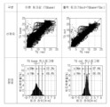
- Figure 6 is a diagram showing the accuracy of the output torque calculated by the vehicle mechanical compressor torque calculation method of Figure 1 in the form of a scatter plot and residual distribution.
- FIG. 1 is a flowchart illustrating a vehicle mechanical compressor torque calculation method according to an embodiment of the present invention
- FIG. 2 is a system diagram illustrating an artificial neural network model for calculating a torque compensation value in the vehicle mechanical compressor torque calculation method of FIG. 1
- FIG. 3 is a system diagram illustrating a vehicle including an air conditioning device controlled by the vehicle mechanical compressor torque calculation method of FIG. 1
- FIG. 4 is a cross-sectional view illustrating a vehicle mechanical compressor included in the air conditioning device of FIG. 3
- FIG. 5 is a diagram illustrating the accuracy of the output torque calculated by the vehicle mechanical compressor torque calculation method of FIG. 1 in the form of a time series torque change
- FIG. 6 is a diagram illustrating the accuracy of the output torque calculated by the vehicle mechanical compressor torque calculation method of FIG. 1 in the form of a scatter plot and a residual distribution.
- a vehicle may include a prime mover (100) that generates power and an air conditioning device (200) that receives some of the power generated by the prime mover (100) to provide heating and cooling inside the vehicle.
- the above-mentioned engine (100) can be formed by an internal combustion engine that converts chemical energy into mechanical energy, a motor that converts electrical energy into mechanical energy, etc.
- the vehicle mechanical compressor (210) may be formed as a so-called variable capacity swash plate type. That is, the vehicle mechanical compressor (210) comprises a housing (211), a rotating shaft (212) rotatably mounted on the housing (211), a pulley (213) that receives power from the motor (100) and rotates, a clutch (214) that selectively engages the pulley (213) and the rotating shaft (212), a swash plate (215) that is accommodated in the crank chamber (V4) of the housing (211) and rotates together with the rotating shaft (212), a piston (216) that is inserted into the bore (211a) of the housing (211) and reciprocates by the swash plate (215) to suck in and compress refrigerant and discharge it into the discharge chamber (V3) of the housing (211), and a stroke of the piston (216) is controlled by adjusting the angle of inclination of the swash plate (215) so that the refrigerant in the discharge chamber (V3)
- the vehicle mechanical compressor torque calculation method may include a sensor data receiving step (S1) of receiving the sensor data, and a first calculation step (S2) of calculating the theoretical torque value (TQbase) of the vehicle mechanical compressor (210) by substituting the sensor data received in the sensor data receiving step (S1) into a pre-determined relational expression.
- the vehicle mechanical compressor torque calculation method may further include a count data generation step (S3) of generating count data that counts the time elapsed since the vehicle mechanical compressor (210) is started (vehicle mechanical compressor driving time), a data normalization step (S4) of normalizing the sensor data received in the sensor data reception step (S1) and the count data generated in the count data generation step (S3) to a number greater than or equal to 0 and less than or equal to 1, and a second calculation step (S5) of inputting the sensor data and count data normalized in the data normalization step (S4) into a pre-learned artificial neural network model to calculate a torque correction value (TQai) for the theoretical torque value (TQbase).
- a count data generation step S3 of generating count data that counts the time elapsed since the vehicle mechanical compressor (210) is started (vehicle mechanical compressor driving time)
- S4 data normalization step
- S4 of normalizing the sensor data received in the sensor data reception step (S1) and the count data generated in the count data generation step (S
- the vehicle mechanical compressor torque calculation method may further include a third calculation step (S6) of calculating the output torque (TQout) of the vehicle mechanical compressor (210) by adding the theoretical torque value (TQbase) calculated in the first calculation step (S2) and the torque compensation value (TQai) calculated in the second calculation step (S5).
- S6 a third calculation step of calculating the output torque (TQout) of the vehicle mechanical compressor (210) by adding the theoretical torque value (TQbase) calculated in the first calculation step (S2) and the torque compensation value (TQai) calculated in the second calculation step (S5).
- TQbase is the theoretical torque value
- vs is the volume per unit mass of the refrigerant of the air conditioner (200)
- Ps is the suction pressure of the vehicle mechanical compressor (210)
- Pd is the discharge pressure of the vehicle mechanical compressor (210)
- Nc is the rotational speed per minute of the vehicle mechanical compressor (210)
- n is the isentropic index.
- the discharge pressure (Pd) of the vehicle mechanical compressor (210) is the sensor data measured by the sensor (250), and the volume per unit mass of the refrigerant of the air conditioning device (vs), the suction pressure (Ps) of the vehicle mechanical compressor, and the mass flow rate of the refrigerant of the air conditioning device ( ) may be a value calculated using the sensor data rather than a value measured from the sensor (250). That is, at least one of the data other than the discharge pressure (Pd) of the vehicle mechanical compressor (210) may be obtained by a regression calculation formula combining measurement values held without a separate sensor.
- the suction pressure (Ps) of the vehicle mechanical compressor is obtained by calculation.
- Pd discharge pressure
- the maximum-minimum normalization method is used, but it is not limited to this and other methods such as a standardization method may be used.
- the number and configuration of the first parameter (P1) and the second parameter (P2) may be appropriately modified, but the four first parameters (P1) and the three second parameters (P2) are selected through the artificial neural network model, and an explanation of how the four first parameters (P1) are obtained by combining the sensor data and the count data, how the three second parameters (P2) are obtained by combining the four first parameters (P1), and how the torque compensation value (TQai) is obtained by combining the three second parameters (P2) will be omitted.
- the suction pressure of the vehicle mechanical compressor and the differential pressure between the discharge pressure and the suction pressure may be calculated based on the sensor data, which is the discharge pressure of the vehicle mechanical compressor, and then used as the input values.
- the difference between the outside temperature and the indoor temperature, the difference between the outside temperature and the evaporator temperature, and the difference between the outside temperature and the duct discharge temperature can be calculated and then used as the input values.
- the vehicle mechanical compressor (210) can receive some of the power generated by the engine (100) to suck and compress the refrigerant. That is, when the engine (100) is rotated, the pulley (213) is rotated by being linked to the engine (100) through, for example, a belt, and the rotation shaft (212) can be rotated by contacting the pulley (213) by the clutch (214).
- the swash plate (215) is rotated together with the rotation shaft (212), the piston (216) reciprocates, and the refrigerant in the suction chamber (V1) is sucked into the compression chamber of the bore (211a), compressed, and then discharged into the discharge chamber (V3).
- the refrigerant discharged into the discharge chamber (V3) of the vehicle mechanical compressor (210) sequentially passes through the first heat exchanger (220), the expansion unit (230), and the second heat exchanger (240) through a pipe, and then flows back into the suction chamber (V1) of the vehicle mechanical compressor (210).
- the heat released or absorbed by the refrigerant as it passes through the first heat exchanger (220) and the second heat exchanger (240) can provide cooling and heating to the passenger compartment of the vehicle.
- the air conditioning device (200) according to the present embodiment and the vehicle including the same can be controlled as follows for optimal driving.
- the sensor (250) can measure the discharge pressure of the mechanical compressor (210) and transmit the sensor data to the air conditioning control unit (270).
- the above air conditioning control unit (270) can calculate the output torque (TQout) of the vehicle mechanical compressor (210) based on the sensor data received from the sensor (250) and the count data generated by itself.
- the air conditioning control unit (270) can calculate the theoretical torque value (TQbase) by substituting the sensor data received from the sensor (250) into the relational expression according to the sensor data receiving step (S1) and the first calculation step (S2).
- the air conditioning control unit (270) can calculate the torque compensation value (TQai) by normalizing the sensor data received from the sensor (250) and the count data generated by itself into a numerical value greater than or equal to 0 and less than or equal to 1 according to the sensor data receiving step (S1), the count data generating step (S3), the data normalization step (S4), and the second calculation step (S5) and then inputting the normalized sensor data and the count data into the artificial neural network model.
- TQai torque compensation value
- the air conditioning control unit (270) can calculate the output torque (TQout) by adding the torque correction value (TQai) to the theoretical torque value (TQbase).
- the air conditioning control unit (270) can control the stroke of the vehicle mechanical compressor (210) by controlling the valve (219) of the vehicle mechanical compressor (210) based on the calculated output torque (TQout).
- the valve (219) can be controlled by the air conditioning control unit (270) to increase the amount of refrigerant flowing into the inflow path (not shown) from the discharge chamber (V3). Then, the pressure of the crank chamber (V4) increases, and the sum of the moment of the swash plate (215) due to the pressure of the crank chamber (V4) and the moment due to the return spring of the swash plate (215) (hereinafter, referred to as the first moment) can increase.
- the inclination angle of the swash plate (215) decreases, the stroke of the piston (216) decreases, and the refrigerant discharge amount can decrease.
- the inclination angle of the swash plate (215) can be measured as the angle between the rotation axis (212) of the swash plate (215) and the normal line of the swash plate (215) based on the rotation center of the swash plate (215).
- the valve (219) can be controlled by the air conditioning control unit (270) to reduce the amount of refrigerant flowing into the inflow path (not shown) from the discharge chamber (V3). Then, the pressure of the crank chamber (V4) can be reduced, and the first moment can be reduced. And, since the first moment becomes smaller than the second moment, the inclination angle of the swash plate (215) increases, the stroke of the piston (216) increases, and the refrigerant discharge amount can be increased.
- the opening amount of the inflow passage (not shown) must be reduced so that the amount of refrigerant flowing into the crankcase (V4) from the discharge chamber (V3) must be reduced, and the refrigerant in the crankcase (V4) must be discharged to the outside of the crankcase (V4).
- the discharge passage (218) that guides the refrigerant in the crankcase (V4) to the suction chamber (V1) and the orifice hole that depressurizes the refrigerant passing through the discharge passage (218) to prevent an increase in the pressure in the suction chamber (V1) are provided.
- the valve (219) can be controlled by the air conditioning control unit (270) to maintain the amount of refrigerant flowing into the inflow path (not shown) from the discharge chamber (V3). Then, the first moment and the second moment are maintained in the same state, the inclination angle of the swash plate (215) is maintained in a steady state, and the stroke of the piston (216) and the refrigerant discharge amount can be maintained constant.
- the compression reaction force of the piston (216) is proportional to the compression amount
- the compression reaction force of the piston (216) and the second moment increase as the inclination angle of the swash plate (215) increases.
- the pressure of the crank chamber (V4) for maintaining the inclination angle of the swash plate (215) also increases. That is, when the inclination angle of the swash plate (215) is maintained in a steady state in a relatively large state, a greater pressure is required in the crank chamber (V4) than in the crank chamber (V4) when the inclination angle of the swash plate (215) is maintained in a steady state in a relatively small state.
- the vehicle can be operated while providing optimal cooling and heating.
- the present embodiment calculates the output torque (TQout) by adding the theoretical torque value (TQbase) obtained through the above relational expression and the torque correction value (TQai) obtained through the artificial neural network model, so that the output torque (TQout) can be accurately calculated, as shown in FIGS. 5 and 6.
- the refrigerant discharge amount of the vehicle mechanical compressor (210) is appropriately controlled, so that problems such as a decrease in cooling performance and efficiency, a decrease in vehicle fuel efficiency, and engine stalling can be suppressed.
- the artificial neural network model that calculates the torque compensation value (TQai) is relatively simpler than the artificial neural network model that directly calculates the output torque (TQout), and thus is easy to develop and can also be easily redeveloped according to changes in conditions.
- the present embodiment which calculates the basic theoretical torque value (TQbase) using a predetermined relational expression, calculates the torque compensation value (TQai) to supplement the theoretical torque value (TQbase) using an artificial neural network model, and calculates the output torque (TQout) by adding the torque compensation value (TQai) to the theoretical torque value (TQbase), can be an efficient, effective, universal, and realistic alternative for accurately calculating the output torque (TQout).
- the time series data characteristics that change over time after the start-up of the air conditioner (200) are reflected in the artificial neural network model, thereby enabling more accurate calculation of the torque compensation value (TQai).
- the initial start-up time corresponds to the time when the torque is the highest, and in order to identify the initial start-up time and increase the prediction accuracy when the torque is high, it may be desirable that the count data be reset every time the air conditioner is turned on.
- the sensor data received from the sensor (250), the count data generated from the air conditioning control unit (270), and the calculated values obtained by calculating from the sensor data may have different scales.
- the dependency of the torque compensation value (TQai) on each data becomes proportional to the scale of the data. That is, the influence of important but small-scale data on the torque compensation value (TQai) becomes small, and the influence of unimportant but large-scale data on the torque compensation value (TQai) becomes large. Accordingly, a torque compensation value (TQai) with low accuracy may be calculated.
- the present embodiment normalizes all of the sensor data received from the sensor (250), the count data generated from the air conditioning control unit (270), and the calculated values obtained by calculating from the sensor data to a value greater than or equal to 0 and less than or equal to 1, and then calculates the torque compensation value (TQai) from the normalized data, thereby calculating a torque compensation value (TQai) with high accuracy.
- the theoretical torque value (TQbase) when calculating the theoretical torque value (TQbase), the above relationship based on the physical formula was used, but it is not limited thereto. That is, after deriving an empirical formula from data acquired through multiple experiments in advance, the theoretical torque value (TQbase) can also be calculated using the derived empirical formula.
- the artificial neural network model should be trained to calculate a torque compensation value (TQai) close to the difference between the theoretical torque value (TQbase) calculated by the empirical formula and the actual value (TQreal) of the output torque (TQout).
Landscapes
- Engineering & Computer Science (AREA)
- Theoretical Computer Science (AREA)
- Physics & Mathematics (AREA)
- Evolutionary Computation (AREA)
- General Physics & Mathematics (AREA)
- Health & Medical Sciences (AREA)
- Artificial Intelligence (AREA)
- Mechanical Engineering (AREA)
- Computing Systems (AREA)
- General Health & Medical Sciences (AREA)
- General Engineering & Computer Science (AREA)
- Software Systems (AREA)
- Databases & Information Systems (AREA)
- Multimedia (AREA)
- Life Sciences & Earth Sciences (AREA)
- Biomedical Technology (AREA)
- Biophysics (AREA)
- Computational Linguistics (AREA)
- Data Mining & Analysis (AREA)
- Molecular Biology (AREA)
- Medical Informatics (AREA)
- Mathematical Physics (AREA)
- Computer Vision & Pattern Recognition (AREA)
- Thermal Sciences (AREA)
- Compressors, Vaccum Pumps And Other Relevant Systems (AREA)
Abstract
본 발명은 차량용 기계식 압축기 토크 연산 방법에 관한 것으로서, 차량용 기계식 압축기를 포함하는 공조 장치에 설치된 센서에서 측정된 센서 데이터를 수신하는 센서 데이터 수신 단계; 사전에 결정된 관계식을 통해 상기 센서 데이터로부터 상기 차량용 기계식 압축기의 이론 토크값을 연산하는 제1 연산 단계; 사전에 학습된 인공신경망 모델을 통해 상기 센서 데이터로부터 상기 이론 토크값에 대한 토크 보정값을 연산하는 제2 연산 단계; 상기 이론 토크값과 상기 토크 보정값을 합하여 상기 차량용 기계식 압축기의 출력 토크를 연산하는 제3 연산 단계;를 포함함으로써, 상기 차량용 기계식 압축기의 출력 토크를 정확하게 연산할 수 있다. 이에 따라, 차량용 기계식 압축기의 냉매 토출량이 적절히 조절될 수 있어, 냉방 성능 및 효율이 향상되고, 차량 연비가 향상되며, 시동 꺼짐이 예방될 수 있다. * 대표도 : 도 1
Description
본 발명은, 차량용 기계식 압축기 토크 연산 방법에 관한 것으로서, 더욱 상세하게는, 차량용 기계식 압축기의 출력 토크를 정확하게 연산할 수 있도록 한 차량용 기계식 압축기 토크 연산 방법에 관한 것이다.
일반적으로, 차량은 운행에 필요한 동력을 발생시키는 원동기를 포함하고, 원동기는 화학적 에너지를 기계적 에너지로 변환하는 내연 기관 엔진, 전기 에너지를 기계적 에너지로 변환하는 모터 등으로 형성된다.
여기서, 내연 기관 엔진을 원동기로 사용하는 차량은 내연 기관 차량이라 지칭되고, 내연 기관 엔진과 모터를 원동기로 사용하는 차량은 하이브리드 차량이라 지칭되며, 모터를 원동기로 사용하는 차량은 전기 차량이라 지칭된다.
한편, 차량은 원동기의 종류와는 무관하게 실내의 냉난방을 위한 공조 장치를 포함하고, 공조 장치는 통상적으로 증기 압축 냉동 사이클로 형성된다. 즉, 상기 공조 장치는, 원동기로부터 동력을 전달받아 저온 저압의 기상 냉매를 고온 고압의 기상 냉매로 압축하는 압축기, 상기 압축기에 의해 압축된 고온 고압의 기상 냉매를 저온 고압의 액상 냉매로 냉각(응축)시키는 제1 열교환기, 상기 제1 열교환기에 의해 냉각된 저온 고압의 액상 냉매를 저온 저압의 액상 냉매로 팽창시키는 팽창 유닛 및 상기 팽창 유닛에 의해 팽창된 저온 저압의 액상 냉매를 저온 저압의 기상 냉매로 가열(증발)시키는 제2 열교환기를 포함한다.
여기서, 상기 압축기는 압축 방식에 따라 피스톤의 왕복운동을 통해 냉매를 압축하는 왕복식 압축기와 회전운동을 하면서 압축을 수행하는 회전식 압축기로 분류되고, 상기 왕복식 압축기는 동력 전달방식에 따라 크랭크를 사용하여 복수의 피스톤으로 동력을 전달하는 크랭크식 압축기, 사판이 설치된 회전축으로 동력을 전달하는 사판식 압축기 등으로 분류되고, 상기 회전식 압축기는 회전하는 로터리축과 베인을 사용하는 베인 로터리식 압축기, 선회 스크롤과 고정 스크롤을 사용하는 스크롤식 압축기로 분류될 수 있다.
또한, 상기 압축기는 구동 방식에 따라 차량의 원동기를 사용하는 기계식 압축기 및 모터를 사용하는 전동식 압축기로 분류될 수도 있다.
여기서, 사판식 압축기는 통상 기계식으로 형성되고, 기계식으로 형성되고 차량에 탑재되는 사판식 압축기를 차량용 기계식 압축기라 하면, 차량용 기계식 압축기는 최근 압축 성능 및 효율 향상을 위해 사판의 경사각을 조절하여 피스톤의 스트로크를 조절함으로써 냉매 토출량을 조절하는 소위 가변 용량 방식으로 형성되고 있다.
즉, 차량용 기계식 압축기는, 하우징, 상기 하우징에 회전 가능하게 장착되는 회전축, 차량의 원동기로부터 동력을 전달받아 회전되는 풀리, 상기 풀리와 상기 회전축을 선택적으로 단속시키는 클러치, 상기 하우징의 크랭크실에 수용되고 상기 회전축과 함께 회전되는 사판, 상기 사판에 의해 왕복 운동되며 냉매를 흡입하고 압축하여 상기 하우징의 토출실로 토출하는 피스톤, 상기 사판의 경사각이 조절되어 상기 피스톤의 스트로크가 조절되도록 상기 토출실의 냉매를 상기 크랭크실로 안내하는 유입유로 및 상기 유입유로의 개도량을 조절하는 밸브를 포함한다.
그리고, 이러한 차량용 기계식 압축기를 포함하는 공조 장치는 공조 제어 유닛을 통해 차량용 기계식 압축기의 출력 토크를 연산하고, 연산된 출력 토크를 기초로 상기 밸브를 조절하여 상기 사판식 차량용 기계식 압축기의 스트로크(더욱 정확히는, 피스톤의 스트로크)를 조절한다.
여기서, 종래의 공조 장치는 상기 공조 장치에 설치되는 센서에서 측정된 센서 데이터를 상기 차량용 기계식 압축기의 출력 토크를 연산하는데에도 이용한다.
이와 같이, 상기 차량용 기계식 압축기의 스트로크가 조절됨에 따라 상기 차량용 기계식 압축기의 냉매 토출량이 가변된다.
그러나, 이러한 종래의 차량용 기계식 압축기 토크 연산 방법은, 출력 토크가 정확하게 연산되지 못하는 문제점이 있었다. 이에 따라, 차량용 기계식 압축기의 냉매 토출량이 적절히 조절되지 못하여, 냉방 성능 및 효율 저하, 차량 연비 저하, 시동 꺼짐 등의 문제점이 발생되었다.
따라서, 본 발명은, 출력 토크를 정확하게 연산할 수 있는 차량용 기계식 압축기 토크 연산 방법을 제공하는 것을 목적으로 한다.
본 발명은, 상기한 바와 같은 목적 달성을 위해, 차량용 기계식 압축기를 포함하는 공조 장치에 설치된 센서에서 측정된 센서 데이터를 수신하는 센서 데이터 수신 단계; 사전에 결정된 관계식을 통해 상기 센서 데이터로부터 상기 차량용 기계식 압축기의 이론 토크값을 연산하는 제1 연산 단계; 사전에 학습된 인공신경망 모델을 통해 상기 센서 데이터로부터 상기 이론 토크값에 대한 토크 보정값을 연산하는 제2 연산 단계; 상기 이론 토크값과 상기 토크 보정값을 합하여 상기 차량용 기계식 압축기의 출력 토크를 연산하는 제3 연산 단계;를 포함하는 차량용 기계식 압축기 토크 연산 방법을 제공한다.
상기 차량용 기계식 압축기의 구동 시간에 대한 카운트 데이터를 생성하는 카운트 데이터 생성 단계를 더 포함하고, 상기 인공신경망 모델은 상기 센서 데이터와 상기 카운트 데이터로부터 상기 토크 보정값을 연산할 수 있다.
상기 카운트 데이터는 상기 공조 장치가 켜지는 시점마다 리셋 될 수 있다.
상기 센서 데이터와 상기 카운트 데이터를 0 이상 1 이하의 수치로 정규화하는 데이터 정규화 단계를 더 포함하고, 상기 인공신경망 모델은 정규화된 센서 데이터와 카운트 데이터로부터 상기 토크 보정값을 연산할 수 있다.
상기 인공신경망 모델은 상기 센서 데이터와 상기 카운트 데이터로부터 복수의 1차 파라미터 값들을 연산하고, 상기 복수의 1차 파라미터 값들을 조합하여 적어도 하나의 2차 파라미터 값을 연산하며, 상기 적어도 하나의 2차 파리미터 값을 이용하여 상기 토크 보정값을 연산할 수 있다.
상기 인공신경망 모델에 입력되는 입력 변수는 적어도 4개 이상일 수 있다.
상기 관계식은 이고, TQbase는 상기 이론 토크값, vs는 상기 공조 장치의 냉매의 단위 질량당 체적, Ps는 상기 차량용 기계식 압축기의 흡입압, Pd는 상기 차량용 기계식 압축기의 토출압, 은 상기 공조 장치의 냉매의 질량 유량이고, Nc는 상기 차량용 기계식 압축기의 분당 회전수이고, n은 아이젠트로픽 인덱스일 수 있다.
상기 차량용 기계식 압축기의 토출압은 상기 센서에서 측정된 센서 데이터일 수 있다.
상기 공조 장치의 냉매의 단위 질량당 체적, 상기 차량용 기계식 압축기의 흡입압, 상기 공조 장치의 냉매의 질량 유량 중 적어도 하나는 상기 센서 데이터를 이용하여 연산된 값일 수 있다.
상기 차량용 기계식 압축기의 흡입압은 상기 센서 데이터를 이용하여 연산된 값일 수 있다.
본 발명에 의한 차량용 기계식 압축기 토크 연산 방법은, 차량용 기계식 압축기를 포함하는 공조 장치에 설치된 센서에서 측정된 센서 데이터를 수신하는 센서 데이터 수신 단계; 사전에 결정된 관계식을 통해 상기 센서 데이터로부터 상기 차량용 기계식 압축기의 이론 토크값을 연산하는 제1 연산 단계; 사전에 학습된 인공신경망 모델을 통해 상기 센서 데이터로부터 상기 이론 토크값에 대한 토크 보정값을 연산하는 제2 연산 단계; 상기 이론 토크값과 상기 토크 보정값을 합하여 상기 차량용 기계식 압축기의 출력 토크를 연산하는 제3 연산 단계;를 포함함으로써, 상기 차량용 기계식 압축기의 출력 토크를 정확하게 연산할 수 있다. 이에 따라, 차량용 기계식 압축기의 냉매 토출량이 적절히 조절될 수 있어, 냉방 성능 및 효율이 향상되고, 차량 연비가 향상되며, 시동 꺼짐이 예방될 수 있다.
도 1은 본 발명의 일 실시예에 따른 차량용 기계식 압축기 토크 연산 방법을 도시한 순서도,
도 2는 도 1의 차량용 기계식 압축기 토크 연산 방법에서 토크 보정값을 연산하는 인공신경망 모델을 도시한 계통도,
도 3은 도 1의 차량용 기계식 압축기 토크 연산 방법에 의해 제어되는 공조 장치를 포함하는 차량을 도시한 계통도,
도 4는 도 3의 공조 장치에 포함되는 차량용 기계식 압축기를 도시한 단면도,
도 5는 도 1의 차량용 기계식 압축기 토크 연산 방법으로 연산된 출력 토크의 정확도를 시계열 토크 변화 형태로 도시한 도표,
도 6은 도 1의 차량용 기계식 압축기 토크 연산 방법으로 연산된 출력 토크의 정확도를 산점도와 잔차 분포 형태로 도시한 도표이다.
이하, 본 발명에 의한 차량용 기계식 압축기 토크 연산 방법을 참조하여 상세히 설명한다.
도 1은 본 발명의 일 실시예에 따른 차량용 기계식 압축기 토크 연산 방법을 도시한 순서도이고, 도 2는 도 1의 차량용 기계식 압축기 토크 연산 방법에서 토크 보정값을 연산하는 인공신경망 모델을 도시한 계통도이고, 도 3은 도 1의 차량용 기계식 압축기 토크 연산 방법에 의해 제어되는 공조 장치를 포함하는 차량을 도시한 계통도이고, 도 4는 도 3의 공조 장치에 포함되는 차량용 기계식 압축기를 도시한 단면도이고, 도 5는 도 1의 차량용 기계식 압축기 토크 연산 방법으로 연산된 출력 토크의 정확도를 시계열 토크 변화 형태로 도시한 도표이며, 도 6은 도 1의 차량용 기계식 압축기 토크 연산 방법으로 연산된 출력 토크의 정확도를 산점도와 잔차 분포 형태로 도시한 도표이다.
도 3을 참조하면, 본 발명의 일 실시예에 따른 차량은, 동력을 발생시키는 원동기(100) 및 상기 원동기(100)에서 발생된 동력 중 일부를 전달받아 실내의 냉난방을 제공하는 공조 장치(200)를 포함할 수 있다.
상기 원동기(100)는 화학적 에너지를 기계적 에너지로 변환하는 내연 기관 엔진, 전기 에너지를 기계적 에너지로 변환하는 모터 등으로 형성될 수 있다.
상기 공조 장치(200)는 증기 압축 냉동 사이클로 형성될 수 있다. 즉, 상기 공조 장치(200)는, 상기 원동기(100)로부터 동력을 전달받아 저온 저압의 기상 냉매를 고온 고압의 기상 냉매로 압축하는 차량용 기계식 압축기(210), 상기 차량용 기계식 압축기(210)에 의해 압축된 고온 고압의 기상 냉매를 저온 고압의 액상 냉매로 냉각(응축)시키는 제1 열교환기(220), 상기 제1 열교환기(220)에 의해 냉각된 저온 고압의 액상 냉매를 저온 저압의 액상 냉매로 팽창시키는 팽창 유닛(230) 및 상기 팽창 유닛(230)에 의해 팽창된 저온 저압의 액상 냉매를 저온 저압의 기상 냉매로 가열(증발)시키는 제2 열교환기(240)를 포함할 수 있다.
여기서, 도 4를 참조하면, 상기 차량용 기계식 압축기(210)는 소위 가변 용량 사판식 으로 형성될 수 있다. 즉, 상기 차량용 기계식 압축기(210)는 하우징(211), 상기 하우징(211)에 회전 가능하게 장착되는 회전축(212), 상기 원동기(100)로부터 동력을 전달받아 회전되는 풀리(213), 상기 풀리(213)와 상기 회전축(212)을 선택적으로 단속시키는 클러치(214), 상기 하우징(211)의 크랭크실(V4)에 수용되고 상기 회전축(212)과 함께 회전되는 사판(215), 상기 하우징(211)의 보어(211a)에 삽입되고 상기 사판(215)에 의해 왕복 운동되며 냉매를 흡입하고 압축하여 상기 하우징(211)의 토출실(V3)로 토출하는 피스톤(216), 상기 사판(215)의 경사각이 조절되어 상기 피스톤(216)의 스트로크가 조절되도록 상기 토출실(V3)의 냉매를 상기 크랭크실(V4)로 안내하는 유입유로(미도시), 상기 크랭크실(V4)의 냉매를 상기 하우징(211)의 흡입실(V1)로 안내하는 배출유로(218) 및 상기 유입유로(미도시)의 개도량을 조절하는 밸브(예를 들어, 기계식 압력 조절 밸브 또는 전자식 압력 조절 밸브)(219)를 포함할 수 있다.
그리고, 상기 공조 장치(200)는 상기 차량용 기계식 압축기(210)의 토출압을 측정하는 센서(250) 및 상기 센서(250)에서 측정된 센서 데이터를 수신하고 상기 차량용 기계식 압축기(210)의 출력 토크(TQout)를 연산하며 상기 출력 토크(TQout)에 기초하여 상기 밸브(219)를 제어하는 공조 제어 유닛(270)을 더 포함하고, 상기 공조 제어 유닛(270)은 도 1에 도시된 차량용 기계식 압축기 토크 연산 방법에 따라 상기 차량용 기계식 압축기(210)의 출력 토크(TQout)를 연산하도록 형성될 수 있다.
구체적으로, 상기 차량용 기계식 압축기 토크 연산 방법은 상기 센서 데이터를 수신하는 센서 데이터 수신 단계(S1) 및 상기 센서 데이터 수신 단계(S1)에서 수신한 센서 데이터를 사전에 결정된 관계식에 대입시켜 상기 차량용 기계식 압축기(210)의 이론 토크값(TQbase)을 연산하는 제1 연산 단계(S2)를 포함할 수 있다.
그리고, 상기 차량용 기계식 압축기 토크 연산 방법은 상기 차량용 기계식 압축기(210)가 시동된 이후 경과된 시간(차량용 기계식 압축기 구동 시간)을 카운트한 카운트 데이터를 생성하는 카운트 데이터 생성 단계(S3), 상기 센서 데이터 수신 단계(S1)에서 수신한 센서 데이터와 상기 카운트 데이터 생성 단계(S3)에서 생성한 카운트 데이터를 각각 0 이상 1 이하의 수치로 정규화하는 데이터 정규화 단계(S4) 및 상기 데이터 정규화 단계(S4)에서 정규화된 센서 데이터와 카운트 데이터를 사전에 학습된 인공신경망 모델에 대입시켜 상기 이론 토크값(TQbase)에 대한 토크 보정값(TQai)을 연산하는 제2 연산 단계(S5)를 더 포함할 수 있다.
그리고, 상기 차량용 기계식 압축기 토크 연산 방법은 상기 제1 연산 단계(S2)에서 연산된 상기 이론 토크값(TQbase)과 상기 제2 연산 단계(S5)에서 연산된 상기 토크 보정값(TQai)을 합하여 상기 차량용 기계식 압축기(210)의 출력 토크(TQout)를 연산하는 제3 연산 단계(S6)를 더 포함할 수 있다.
상기 관계식은 다음과 같은 물리식일 수 있다.

이때, TQbase는 상기 이론 토크값, vs는 상기 공조 장치(200)의 냉매의 단위 질량당 체적, Ps는 상기 차량용 기계식 압축기(210)의 흡입압, Pd는 상기 차량용 기계식 압축기(210)의 토출압,  은 상기 공조 장치(200)의 냉매의 질량 유량이고, Nc는 상기 차량용 기계식 압축기(210)의 분당 회전수이고, n은 아이젠트로픽 인덱스(isentropic index)이다.
여기서, 센서 설치에 소요되는 원가, 공수 등을 절감하기 위해, 상기 차량용 기계식 압축기(210)의 토출압(Pd)만 상기 센서(250)에서 측정된 상기 센서 데이터이고, 상기 공조 장치의 냉매의 단위 질량당 체적(vs), 상기 차량용 기계식 압축기의 흡입압(Ps), 상기 공조 장치의 냉매의 질량 유량( ) 중 적어도 하나는 상기 센서(250)로부터 측정되는 값이 아닌 상기 센서 데이터를 이용하여 연산된 값일 수 있다. 즉, 상기 차량용 기계식 압축기(210)의 토출압(Pd) 이외의 데이터들 중 적어도 하나는 별도의 센서 없이 보유하고 있는 측정값을 조합한 회귀 연산식으로 얻어질 수 있다. 이때, 상기 차량용 기계식 압축기의 흡입압(Ps)이 연산으로 얻어지는 것이 바람직할 수 있다. 그리고, 원가, 공수 등을 최대한 절감하기 위해서는, 상기 차량용 기계식 압축기(210)의 토출압(Pd) 이외의 데이터들 모두가 연산으로 얻어지는 것이 바람직할 수 있다.
상기 데이터 정규화 단계(S4)에서는 예를 들어 최대-최소 정규화 방법을 이용하나, 이에 한정되는 것은 아니고 표준화 방법 등 다른 방법을 이용할 수도 있다.
상기 인공신경망 모델은 사전에 많은 테스트를 통해 얻어진 상기 이론 토크값(TQbase)과 차량용 기계식 압축기(210)의 출력 토크(TQout)의 실측치(TQreal) 사이 차이값을 학습하여 나름의 연산 체계를 수립하고 이를 이용하여 상기 이론 토크값(TQbase)과 상기 실측치(TQreal) 사이 차이값에 근접하는 상기 토크 보정값(TQai)을 연산하도록 형성되는데, 본 실시예의 인공신경망 모델은, 도 2에 도시된 바와 같이, 상기 데이터 정규화 단계(S4)에서 정규화된 센서 데이터와 카운트 데이터를 조합하여 4개의 1차 파라미터(P1)를 연산하고, 상기 4개의 1차 파라미터(P1)를 조합하여 3개의 2차 파라미터(P2)를 연산하며, 상기 3개의 2차 파라미터(P2)를 이용하여 상기 토크 보정값(TQai)을 연산할 수 있다.
여기서, 상기 1차 파라미터(P1)와 상기 2차 파라미터(P2)의 개수와 구성은 적절히 변형될 수 있겠으나, 상기 4개의 1차 파라미터(P1) 및 상기 3개의 2차 파라미터(P2)는 상기 인공신경망 모델을 통해 선정된 것으로, 상기 4개의 1차 파라미터(P1)가 상기 센서 데이터와 상기 카운트 데이터를 어떻게 조합하여 얻어진 것인지, 그리고 상기 3개의 2차 파라미터(P2)가 상기 4개의 1차 파라미터(P1)를 어떻게 조합하여 얻어진 것인지, 그리고 상기 토크 보정값(TQai)이 상기 3개의 2차 파라미터(P2)를 어떻게 조합하여 얻어진 것인지에 대한 설명은 생략하겠다.
다만, 상기 1차 파리미터(P1)에 고려되는 입력값이 많을수록 상기 상기 토크 보정값(TQai)의 정확도가 상승되며, 토크 예측의 복잡성을 고려하면, 상기 1차 파리미터(P1)는 적어도 4개의 입력 변수를 고려하는 것이 바람직할 수 있다. 즉, 상기 1차 파리미터(P1)는 상기 센서 데이터와 상기 카운트 데이터 뿐만 아니라 상기 센서 데이터와 회귀 연산식을 이용하여 얻을 수 있는 여러 연산값들(예를 들어, 차량용 기계식 압축기의 흡입압, 밸브(219)에 인가되는 전류값, 제2 열교환기(240)의 온도, 외기 온도 등)도 고려하는 것이 바람직할 수 있다. 이 경우, 상기 센서 데이터인 상기 차량용 기계식 압축기의 토출압을 기초로 상기 차량용 기계식 압축기의 흡입압 및 상기 토출압과 상기 흡입압의 차압을 연산한 후 이를 상기 입력값으로 활용할 수 있다. 또는, 상기 센서 데이터인 상기 차량용 기계식 압축기의 토출압을 기초로 외기 온도와 실내 온도의 차이값, 외기 온도와 증발기 온다의 차이값, 외기 온도와 덕트 토출 온도의 차이값을 연산한 후 이를 상기 입력값으로 활용할 수 있다.
이하, 본 실시예에 따른 공조 장치(200)의 작용효과에 대해 설명한다.
즉, 상기 차량이 시동되면 상기 원동기(100)가 회전되고, 상기 공조 장치(200)가 시동되면 상기 차량용 기계식 압축기(210)가 상기 원동기(100)에서 발생된 동력 중 일부를 전달받아 냉매를 흡입하고 압축할 수 있다. 즉, 상기 원동기(100)가 회전될 때 상기 풀리(213)가 예를 들어 벨트를 통해 상기 원동기(100)에 연동되어 회전되고, 상기 회전축(212)은 상기 클러치(214)에 의해 상기 풀리(213)에 접촉되어 회전될 수 있다. 그러면, 상기 사판(215)이 상기 회전축(212)과 함께 회전되고, 상기 피스톤(216)은 왕복 운동되며, 상기 흡입실(V1)의 냉매가 상기 보어(211a)의 압축실로 흡입되고 압축된 후 상기 토출실(V3)로 토출될 수 있다. 상기 차량용 기계식 압축기(210)의 토출실(V3)로 토출된 냉매는 배관을 통해 상기 제1 열교환기(220), 상기 팽창 유닛(230) 및 상기 제2 열교환기(240)를 순차적으로 통과한 후 상기 차량용 기계식 압축기(210)의 흡입실(V1)로 다시 유입되는데, 냉매가 상기 제1 열교환기(220)와 상기 제2 열교환기(240)를 통과하며 방출 또는 흡수하는 열로 상기 차량의 승객실에 냉난방이 제공될 수 있다.
여기서, 본 실시예에 따른 공조 장치(200) 및 이를 포함하는 차량은 최적 운전을 위해 다음과 같이 제어될 수 있다.
즉, 도 3에 도시된 바와 같이, 상기 센서(250)는 상기 기계식 압축기(210)의 토출압을 측정하여 상기 공조 제어 유닛(270)으로 상기 센서 데이터를 송신할 수 있다.
상기 공조 제어 유닛(270)은 상기 센서(250)로부터 수신한 상기 센서 데이터 및 자체적으로 생성하는 상기 카운트 데이터에 기초하여 상기 차량용 기계식 압축기(210)의 출력 토크(TQout)를 연산할 수 있다.
구체적으로, 도 1을 참조하면, 상기 공조 제어 유닛(270)은 상기 센서 데이터 수신 단계(S1) 및 상기 제1 연산 단계(S2)에 따라 상기 센서(250)로부터 수신한 센서 데이터를 상기 관계식에 대입시켜 상기 이론 토크값(TQbase)을 연산할 수 있다.
그리고, 도 1 및 도 2를 참조하면, 상기 공조 제어 유닛(270)은 상기 센서 데이터 수신 단계(S1), 상기 카운트 데이터 생성 단계(S3), 상기 데이터 정규화 단계(S4) 및 상기 제2 연산 단계(S5)에 따라 상기 센서(250)로부터 수신한 센서 데이터와 자체적으로 생성한 카운트 데이터를 각각 0 이상 1 이하의 수치로 정규화한 후 상기 인공신경망 모델에 대입시켜 상기 토크 보정값(TQai)을 연산할 수 있다.
그리고, 도 1을 참조하면, 상기 공조 제어 유닛(270)은 상기 이론 토크값(TQbase)에 상기 토크 보정값(TQai)을 합하여 상기 출력 토크(TQout)를 연산할 수 있다.
그리고, 상기 공조 제어 유닛(270)은, 도 3에 도시된 바와 같이, 연산한 상기 출력 토크(TQout)에 기초하여 상기 차량용 기계식 압축기(210)의 밸브(219)를 조절하여 상기 차량용 기계식 압축기(210)의 스트로크를 조절할 수 있다.
구체적으로, 상기 출력 토크(TQout)가 큰 경우, 즉, 냉매 토출량의 감소가 필요한 경우, 상기 밸브(219)가 상기 공조 제어 유닛(270)에 의해 제어되어 상기 토출실(V3)로부터 상기 유입유로(미도시)로 유입되는 냉매량을 증가시킬 수 있다. 그러면, 상기 크랭크실(V4)의 압력이 증가되고, 상기 크랭크실(V4)의 압력에 의한 사판(215) 모멘트와 상기 사판(215)의 리턴 스프링에 의한 모멘트의 합(이하, 제1 모멘트)가 증가될 수 있다. 그리고, 상기 제1 모멘트가 상기 피스톤(216)의 압축 반력에 의한 모멘트(이하, 제2 모멘트)보다 커져, 상기 사판(215)의 경사각은 감소되고, 상기 피스톤(216)의 스트로크가 감소되며, 냉매 토출량이 감소될 수 있다.
여기서, 상기 사판(215)의 경사각은 상기 사판(215)의 회전 중심을 기준으로 상기 사판(215)의 회전축(212)과 상기 사판(215)의 법선 사이 각도로 측정될 수 있다.
반면, 상기 출력 토크(TQout)가 작은 경우, 즉, 냉매 토출량의 증가가 필요한 경우, 상기 밸브(219)가 상기 공조 제어 유닛(270)에 의해 제어되어 상기 토출실(V3)로부터 상기 유입유로(미도시)로 유입되는 냉매량을 감소시킬 수 있다. 그러면, 상기 크랭크실(V4)의 압력이 감소되고, 상기 제1 모멘트가 감소될 수 있다. 그리고, 상기 제1 모멘트가 상기 제2 모멘트보다 작아져, 상기 사판(215)의 경사각은 증가되고, 상기 피스톤(216)의 스트로크가 증가되며, 냉매 토출량이 증가될 수 있다.
여기서, 상기 크랭크실(V4)의 압력이 감소되기 위해서는, 상기 유입유로(미도시)의 개도량이 감소되어 상기 토출실(V3)로부터 상기 크랭크실(V4)로 유입되는 냉매량이 감소되야 할 뿐만 아니라, 상기 크랭크실(V4)의 냉매가 상기 크랭크실(V4)의 외부로 배출되어야 하고, 이를 위하여 상기 크랭크실(V4)의 냉매를 상기 흡입실(V1)로 안내하는 상기 배출유로(218) 및 상기 흡입실(V1)의 압력 상승을 방지하도록 상기 배출유로(218)를 통과하는 냉매를 감압시키는 오리피스 홀이 구비된다.
한편, 상기 출력 토크(TQout)가 적정 수준인 경우, 즉, 냉매 토출량의 유지가 필요한 경우, 상기 밸브(219)가 상기 공조 제어 유닛(270)에 의해 제어되어 상기 토출실(V3)로부터 상기 유입유로(미도시)로 유입되는 냉매량을 유지할 수 있다. 그러면, 상기 제1 모멘트와 상기 제2 모멘트가 같은 상태로 유지되고, 상기 사판(215)의 경사각이 정상상태(steady state)로 유지되고, 상기 피스톤(216)의 스트로크와 냉매 토출량이 일정하게 유지될 수 있다.
여기서, 상기 피스톤(216)의 압축 반력은 압축량에 비례하기 때문에, 상기 피스톤(216)의 압축 반력 및 상기 제2 모멘트는 상기 사판(215)의 경사각이 커질수록 증가된다. 이에 따라, 상기 사판(215)의 경사각이 증가할수록, 상기 사판(215)의 경사각을 유지하기 위한 상기 크랭크실(V4)의 압력도 증가된다. 즉, 상기 사판(215)의 경사각이 상대적으로 큰 상태에서 정상상태로 유지되는 경우의 상기 크랭크실(V4) 압력은 상기 사판(215)의 경사각이 상대적으로 작은 상태에서 정상상태로 유지되는 경우의 상기 크랭크실(V4) 압력보다 더 큰 압력이 요구된다.
이와 같이, 상기 차량용 기계식 압축기(210)의 스트로크가 조건에 맞게 제어됨에 따라, 차량이 최적의 냉난방을 제공하면서 운행될 수 있다.
이 과정에서, 본 실시예는, 상기 출력 토크(TQout)가 상기 관계식을 통해 얻어지는 상기 이론 토크값(TQbase)과 상기 인공신경망 모델을 통해 얻어지는 상기 토크 보정값(TQai)을 합하여 연산됨에 따라, 도 5 및 도 6에 도시된 바와 같이 상기 출력 토크(TQout)가 정확하게 연산될 수 있다. 그리고, 상기 출력 토크(TQout)가 정확하게 연산됨에 따라, 상기 차량용 기계식 압축기(210)의 냉매 토출량이 적절히 조절되어, 냉방 성능 및 효율 저하, 차량 연비 저하, 시동 꺼짐 등의 문제가 억제될 수 있다.
여기서, 본 실시예와 달리 상기 인공신경망 모델로 상기 출력 토크(TQout)를 직접 연산하는 것을 고려해 볼 수 있으나, 실차 환경에서는 실내 온도, 실외 온도, 차량 상태, 차량 주변 환경, 운전자 조작 등 다양하고 복잡한 조건들이 있고, 이러한 조건들의 데이터를 확보하기가 불가능하기 때문에, 출력 토크(TQout)를 직접 연산하는 인공신경망 모델을 개발하기에는 어려움이 있다. 또한, 출력 토크(TQout)를 직접 연산하는 인공신경망 모델을 개발했다 하더라도, 그 인공신경망 모델은 특정 공조 장치(200)와 특정 차량에 한해 개발된 것이라, 공조 장치(200)의 구성요소가 변경되거나 공조 장치(200)가 탑재되는 차량이 변경되는 등 조건이 변경될 경우 인공신경망 모델을 다시 개발하는데 상당한 시간과 비용이 소요된다. 그래서, 출력 토크(TQout)를 직접 연산하는 인공신경망 모델을 개발하는 것은 비효율적이다. 반면, 상기 토크 보정값(TQai)을 연산하는 인공신경망 모델은 출력 토크(TQout)를 직접 연산하는 인공신경망 모델보다 상대적으로 간단하여, 개발이 용이하고, 조건 변경에 따른 재개발도 용이할 수 있다. 이에 따라, 기본적인 이론 토크값(TQbase)을 소정의 관계식으로 연산하고, 이론 토크값(TQbase)을 보완할 토크 보정값(TQai)을 인공신경망 모델로 연산하여, 이론 토크값(TQbase)에 토크 보정값(TQai)을 합해 출력 토크(TQout)를 연산하는 본 실시예는 출력 토크(TQout)를 정확하게 연산하기 위한 효율적, 효과적, 범용적, 현실적인 대안이 될 수 있다.
그리고, 본 실시예는, 상기 센서 데이터 뿐만 아니라 상기 카운트 데이터를 고려함에 따라, 상기 공조 장치(200)의 시동 이후 시간에 따라 변하는 시계열 데이터 특성(예를 들어, 시간이 지남에 따라 냉방 부하가 줄어들기 때문에 점점 낮아지는 토크의 변화)을 상기 인공신경망 모델에 반영함으로써, 상기 토크 보정값(TQai)을 더욱 정확하게 연산할 수 있다. 여기서, 초기 기동 시점에는 토크가 가장 높은 시점에 해당하는데, 초기 기동 시점을 파악하여 토크가 높을 때의 예측 정확도를 높이기 위해, 상기 카운트 데이터는 상기 공조 장치가 켜지는 시점마다 리셋 되는 것이 바람직할 수 있다.
한편, 상기 센서(250)로부터 수신한 센서 데이터, 상기 공조 제어 유닛(270)에서 생성한 카운트 데이터 및 상기 센서 데이터로부터 연산하여 얻는 연산값들은 스케일이 서로 상이할 수 있다. 그런데, 이와 같이 스케일이 서로 상이한 데이터들로부터 바로 토크 보정값(TQai)을 연산할 경우에는, 토크 보정값(TQai)의 각 데이터에 대한 의존도가 데이터의 스케일에 비례하게 된다. 즉, 중요하지만 스케일이 작은 데이터가 토크 보정값(TQai)에 미치는 영향도는 작아지고, 중요하지 않지만 스케일이 큰 데이터가 토크 보정값(TQai)에 미치는 영향도는 커진다. 이에 따라, 정확도가 낮은 토크 보정값(TQai)이 연산될 수 있다. 이를 고려하여, 본 실시예는 상기 센서(250)에서 수신한 센서 데이터, 상기 공조 제어 유닛(270)에서 생성한 카운트 데이터 및 상기 센서 데이터로부터 연산하여 얻는 연산값들을 모두 0 이상 1 이하의 수치로 정규화한 다음, 정규화된 데이터들로부터 토크 보정값(TQai)을 연산함에 따라, 정확도가 높은 토크 보정값(TQai)을 연산할 수 있다.
한편, 본 실시예의 경우 상기 이론 토크값(TQbase)을 연산할 때 물리식에 근거한 상기 관계식을 이용하였으나, 이에 한정되는 것은 아니다. 즉, 사전에 여러 번의 실험을 통해 획득한 데이터로부터 경험식을 도출한 후, 도출된 상기 경험식을 이용하여 이론 토크값(TQbase)을 연산할 수도 있다. 물론, 이 경우, 상기 인공신경망 모델은 상기 경험식으로 연산된 이론 토크값(TQbase)과 출력 토크(TQout)의 실측치(TQreal) 사이 차이에 근접한 토크 보정값(TQai)을 연산하도록 학습되어야 할 것이다.
Claims (10)
- 차량용 기계식 압축기를 포함하는 공조 장치에 설치된 센서에서 측정된 센서 데이터를 수신하는 센서 데이터 수신 단계;사전에 결정된 관계식을 통해 상기 센서 데이터로부터 상기 차량용 기계식 압축기의 이론 토크값을 연산하는 제1 연산 단계;사전에 학습된 인공신경망 모델을 통해 상기 센서 데이터로부터 상기 이론 토크값에 대한 토크 보정값을 연산하는 제2 연산 단계;상기 이론 토크값과 상기 토크 보정값을 합하여 상기 차량용 기계식 압축기의 출력 토크를 연산하는 제3 연산 단계;를 포함하는 차량용 기계식 압축기 토크 연산 방법.
- 제1항에 있어서,상기 차량용 기계식 압축기의 구동 시간에 대한 카운트 데이터를 생성하는 카운트 데이터 생성 단계를 더 포함하고,상기 인공신경망 모델은 상기 센서 데이터와 상기 카운트 데이터로부터 상기 토크 보정값을 연산하는 차량용 기계식 압축기 토크 연산 방법.
- 제2항에 있어서,상기 카운트 데이터는 상기 공조 장치가 켜지는 시점마다 리셋 되는 차량용 기계식 압축기 토크 연산 방법.
- 제2항에 있어서,상기 센서 데이터와 상기 카운트 데이터를 0 이상 1 이하의 수치로 정규화하는 데이터 정규화 단계를 더 포함하고,상기 인공신경망 모델은 정규화된 센서 데이터와 카운트 데이터로부터 상기 토크 보정값을 연산하는 차량용 기계식 압축기 토크 연산 방법.
- 제2항에 있어서,상기 인공신경망 모델은 상기 센서 데이터와 상기 카운트 데이터로부터 복수의 1차 파라미터 값들을 연산하고, 상기 복수의 1차 파라미터 값들을 조합하여 적어도 하나의 2차 파라미터 값을 연산하며, 상기 적어도 하나의 2차 파리미터 값을 이용하여 상기 토크 보정값을 연산하는 차량용 기계식 압축기 토크 연산 방법.
- 제5항에 있어서,상기 인공신경망 모델에 입력되는 입력 변수는 적어도 4개 이상인 것을 특징으로 하는 차량용 기계식 압축기 토크 연산 방법.
- 제1항에 있어서,상기 관계식은 이고,TQbase는 상기 이론 토크값, vs는 상기 공조 장치의 냉매의 단위 질량당 체적, Ps는 상기 차량용 기계식 압축기의 흡입압, Pd는 상기 차량용 기계식 압축기의 토출압, 은 상기 공조 장치의 냉매의 질량 유량이고, Nc는 상기 차량용 기계식 압축기의 분당 회전수이고, n은 아이젠트로픽 인덱스인 차량용 기계식 압축기 토크 연산 방법.
- 제7항에 있어서,상기 차량용 기계식 압축기의 토출압은 상기 센서에서 측정된 센서 데이터인 것을 특징으로 하는 차량용 기계식 압축기 토크 연산 방법.
- 제7항에 있어서,상기 공조 장치의 냉매의 단위 질량당 체적, 상기 차량용 기계식 압축기의 흡입압, 상기 공조 장치의 냉매의 질량 유량 중 적어도 하나는 상기 센서 데이터를 이용하여 연산된 값인 것을 특징으로 하는 차량용 기계식 압축기 토크 연산 방법.
- 제9항에 있어서,상기 차량용 기계식 압축기의 흡입압은 상기 센서 데이터를 이용하여 연산된 값인 것을 특징으로 하는 차량용 기계식 압축기 토크 연산 방법.
Applications Claiming Priority (2)
| Application Number | Priority Date | Filing Date | Title |
|---|---|---|---|
| KR1020230133592A KR20250050497A (ko) | 2023-10-06 | 2023-10-06 | 차량용 기계식 압축기 토크 연산 방법 |
| KR10-2023-0133592 | 2023-10-06 |
Publications (1)
| Publication Number | Publication Date |
|---|---|
| WO2025075271A1 true WO2025075271A1 (ko) | 2025-04-10 |
Family
ID=95283357
Family Applications (1)
| Application Number | Title | Priority Date | Filing Date |
|---|---|---|---|
| PCT/KR2024/009246 Pending WO2025075271A1 (ko) | 2023-10-06 | 2024-07-01 | 차량용 기계식 압축기 토크 연산 방법 |
Country Status (2)
| Country | Link |
|---|---|
| KR (1) | KR20250050497A (ko) |
| WO (1) | WO2025075271A1 (ko) |
Citations (5)
| Publication number | Priority date | Publication date | Assignee | Title |
|---|---|---|---|---|
| KR20020075206A (ko) * | 2001-03-22 | 2002-10-04 | 가부시키가이샤 도요다 지도숏키 | 압축기토크 산출방법, 공조장치 및 엔진제어장치 |
| KR20090071203A (ko) * | 2007-12-27 | 2009-07-01 | 한라공조주식회사 | 차량용 공조장치의 예상토크 산출방법 |
| JP4333668B2 (ja) * | 2005-11-22 | 2009-09-16 | 株式会社デンソー | 内燃機関の制御装置 |
| KR101632751B1 (ko) * | 2010-02-12 | 2016-06-22 | 한온시스템 주식회사 | 차량 공조장치용 압축기의 예상토크 산출방법 |
| US20230116964A1 (en) * | 2020-03-12 | 2023-04-20 | Johnson Controls Tyco IP Holdings LLP | Systems and methods for controlling variable refrigerant flow systems and equipment using artificial intelligence models |
Family Cites Families (1)
| Publication number | Priority date | Publication date | Assignee | Title |
|---|---|---|---|---|
| KR102805342B1 (ko) | 2020-02-19 | 2025-05-13 | 한온시스템 주식회사 | 사판식 압축기 제어 방법 및 사판식 압축기 |
-
2023
- 2023-10-06 KR KR1020230133592A patent/KR20250050497A/ko active Pending
-
2024
- 2024-07-01 WO PCT/KR2024/009246 patent/WO2025075271A1/ko active Pending
Patent Citations (5)
| Publication number | Priority date | Publication date | Assignee | Title |
|---|---|---|---|---|
| KR20020075206A (ko) * | 2001-03-22 | 2002-10-04 | 가부시키가이샤 도요다 지도숏키 | 압축기토크 산출방법, 공조장치 및 엔진제어장치 |
| JP4333668B2 (ja) * | 2005-11-22 | 2009-09-16 | 株式会社デンソー | 内燃機関の制御装置 |
| KR20090071203A (ko) * | 2007-12-27 | 2009-07-01 | 한라공조주식회사 | 차량용 공조장치의 예상토크 산출방법 |
| KR101632751B1 (ko) * | 2010-02-12 | 2016-06-22 | 한온시스템 주식회사 | 차량 공조장치용 압축기의 예상토크 산출방법 |
| US20230116964A1 (en) * | 2020-03-12 | 2023-04-20 | Johnson Controls Tyco IP Holdings LLP | Systems and methods for controlling variable refrigerant flow systems and equipment using artificial intelligence models |
Also Published As
| Publication number | Publication date |
|---|---|
| KR20250050497A (ko) | 2025-04-15 |
Similar Documents
| Publication | Publication Date | Title |
|---|---|---|
| US6484520B2 (en) | Displacement control apparatus for variable displacement compressor, displacement control method and compressor module | |
| US7779821B2 (en) | Intake-air cooling device for internal combustion engine and automobile using the same | |
| EP2581242A1 (en) | Vehicle air-conditioning device, and refrigerant leakage diagnosis method for vehicle air-conditioning device | |
| EP1726829B1 (en) | Control apparatus for variable capacity compressor and method of calculating torque of variable capacity compressor | |
| US7025572B2 (en) | Compressor with integral control unit | |
| US20070039340A1 (en) | Controlling method of air conditioning system for vehicles | |
| EP1726465B1 (en) | Apparatus for and method of calculating torque of variable capacity compressor | |
| US4452571A (en) | Multiple cylinder rotary compressor | |
| CN212898706U (zh) | 模拟高原环境的发动机进排气系统 | |
| CN212202435U (zh) | 一种空压机高低温试验箱 | |
| WO2025075271A1 (ko) | 차량용 기계식 압축기 토크 연산 방법 | |
| JP2005016352A (ja) | 圧縮機出力算出装置およびそれを用いた制御装置 | |
| JP4119143B2 (ja) | 可変容量コンプレッサの駆動トルク算出装置 | |
| US20020104327A1 (en) | Vehicular air conditioner | |
| WO2024205351A1 (ko) | 공조 장치, 이에 대한 제어 방법 및 이에 포함되는 압축기 | |
| JP2003278660A (ja) | 可変容量コンプレッサの駆動トルク算出装置 | |
| CN118776950B (zh) | 一种用于车辆座舱降温热负荷的试验装置及确定方法 | |
| Lee | Performance simulation of scroll compressors | |
| GB2342711A (en) | Air conditioning system for a motor vehicle | |
| KR100681973B1 (ko) | 엔진 구동식 공기 조화 장치 | |
| KR20210105811A (ko) | 사판식 압축기 제어 방법 및 사판식 압축기 | |
| KR102896226B1 (ko) | 용량 가변형 사판식 압축기 | |
| WO2022203261A1 (ko) | 스크롤 압축기 및 이를 포함하는 차량용 공조장치 | |
| KR102797366B1 (ko) | 용량 가변형 사판식 압축기 | |
| CN217236014U (zh) | 用于测试空调性能的系统、空调实验室 |
Legal Events
| Date | Code | Title | Description |
|---|---|---|---|
| 121 | Ep: the epo has been informed by wipo that ep was designated in this application |
Ref document number: 24874830 Country of ref document: EP Kind code of ref document: A1 |