WO2025075096A1 - 骨格部材 - Google Patents
骨格部材 Download PDFInfo
- Publication number
- WO2025075096A1 WO2025075096A1 PCT/JP2024/035465 JP2024035465W WO2025075096A1 WO 2025075096 A1 WO2025075096 A1 WO 2025075096A1 JP 2024035465 W JP2024035465 W JP 2024035465W WO 2025075096 A1 WO2025075096 A1 WO 2025075096A1
- Authority
- WO
- WIPO (PCT)
- Prior art keywords
- less
- steel sheet
- content
- area ratio
- base steel
- Prior art date
- Legal status (The legal status is an assumption and is not a legal conclusion. Google has not performed a legal analysis and makes no representation as to the accuracy of the status listed.)
- Pending
Links
Images
Classifications
-
- C—CHEMISTRY; METALLURGY
- C22—METALLURGY; FERROUS OR NON-FERROUS ALLOYS; TREATMENT OF ALLOYS OR NON-FERROUS METALS
- C22C—ALLOYS
- C22C38/00—Ferrous alloys, e.g. steel alloys
-
- C—CHEMISTRY; METALLURGY
- C22—METALLURGY; FERROUS OR NON-FERROUS ALLOYS; TREATMENT OF ALLOYS OR NON-FERROUS METALS
- C22C—ALLOYS
- C22C38/00—Ferrous alloys, e.g. steel alloys
- C22C38/60—Ferrous alloys, e.g. steel alloys containing lead, selenium, tellurium, or antimony, or more than 0.04% by weight of sulfur
-
- C—CHEMISTRY; METALLURGY
- C21—METALLURGY OF IRON
- C21D—MODIFYING THE PHYSICAL STRUCTURE OF FERROUS METALS; GENERAL DEVICES FOR HEAT TREATMENT OF FERROUS OR NON-FERROUS METALS OR ALLOYS; MAKING METAL MALLEABLE, e.g. BY DECARBURISATION OR TEMPERING
- C21D9/00—Heat treatment, e.g. annealing, hardening, quenching or tempering, adapted for particular articles; Furnaces therefor
- C21D9/46—Heat treatment, e.g. annealing, hardening, quenching or tempering, adapted for particular articles; Furnaces therefor for sheet metals
-
- C—CHEMISTRY; METALLURGY
- C22—METALLURGY; FERROUS OR NON-FERROUS ALLOYS; TREATMENT OF ALLOYS OR NON-FERROUS METALS
- C22C—ALLOYS
- C22C18/00—Alloys based on zinc
-
- C—CHEMISTRY; METALLURGY
- C22—METALLURGY; FERROUS OR NON-FERROUS ALLOYS; TREATMENT OF ALLOYS OR NON-FERROUS METALS
- C22C—ALLOYS
- C22C18/00—Alloys based on zinc
- C22C18/04—Alloys based on zinc with aluminium as the next major constituent
Definitions
- the present invention relates to a skeletal member that has excellent axial crushing properties.
- the present invention relates to a skeletal member that has excellent collision properties when used as a skeletal member for an automobile.
- energy absorbing members arranged at the front and rear of the vehicle body are required to absorb collision energy by plastically deforming the members during a collision, but in the axial collapse of the energy absorbing members, fracture often occurs due to the occurrence of large local strain. If such fracture develops into a large crack and the member collapses, the collision load may be significantly reduced, which may cause instability in the energy absorption performance, and the instability of the energy absorption performance is a major issue in applying high-strength steel plates to the vehicle body. Therefore, it is important to improve the collision performance of the vehicle body by applying materials to the energy absorbing members that are high strength, can withstand high collision loads, suppress collision fracture, and have stable energy absorption performance.
- Non-Patent Document 1 discloses that 980 MPa-class materials with different material structures were applied to test specimens simulating energy absorbing members, and axial crushing tests were performed. The results showed that, compared to dual phase (DP) steel consisting of ferrite and martensite, and transformation-induced plasticity (TRIP) steel containing retained austenite, dual phase steel containing tempered martensite and bainite in addition to retained austenite, the generation of voids during bending deformation is suppressed, and thus the bending fracture resistance during a collision is superior.
- DP dual phase
- TRIP transformation-induced plasticity
- Non-Patent Document 1 only examines the basic characteristics of axial crushing for materials with a material strength of 905 to 925 MPa. Furthermore, when collision deformation is more severe, it is conceivable that further improvements in bending fracture resistance may be necessary. For example, when considering the application of even higher strength steel of the 1180 MPa class or higher, it is unclear whether collision fracture can be suppressed simply by creating a similar material structure, and it may be necessary to apply a material with even better bending properties.
- the present invention focuses on the above points and aims to provide a skeleton member with excellent axial crushing properties by making the base steel plate of the top panel have a soft layer on the surface and a tensile strength of 980 MPa to 1.8 GPa.
- the invention aims to provide a skeleton member for automobiles that combines load-bearing properties and fracture prevention performance during a collision.
- excellent axial crushing properties means that when subjected to an axial crushing test, the material has load-bearing properties and fracture-resistance performance (crack resistance) that are equal to or greater than a specified level, and has excellent shock absorption properties.
- the present inventors conducted extensive research to achieve the above-mentioned object, and as a result, obtained the following findings: That is, the inventors discovered that the effects intended by the present invention can be achieved by satisfying the following [1] to [5], and thus arrived at the present invention.
- the surface layer has a soft surface layer whose Vickers hardness is 84% or less of the Vickers hardness at the 1/4 position of the plate thickness, The thickness of the surface soft layer satisfies the following formula (1), The tensile strength is 980 MPa or more and 1.8 GPa or less. Skeletal components.
- X is the thickness of the surface soft layer ( ⁇ m)
- t is the thickness of the base steel sheet ( ⁇ m)
- [Sb] and [Sn] are the Sb and Sn contents (mass%) in the base steel sheet, respectively.
- the structure in the superficial soft layer is as follows:
- the area ratio of ferrite is 60.0% or more, Among structures other than ferrite, the area ratio of fresh martensite divided by the total area ratio of bainitic ferrite, fresh martensite, and tempered martensite (excluding retained austenite) is 0.5 or less;
- the area ratio of retained austenite is 3.0% or less,
- the structure at 1/4 of the sheet thickness of the base steel sheet is as follows:
- the area ratio of ferrite is 55.0% or less (including 0.0%),
- the total area ratio of bainitic ferrite and tempered martensite (excluding retained austenite) is more than 40.0%, Area ratio of fresh martensite: 10.0% or less (including 0.0%);
- C 0.050% or more and 0.400% or less, Si: 0.02% or more and 3.00% or less, Mn: 1.50% or more and less than 3.50%; P: 0.001% or more and 0.100% or less, S: 0.0001% or more and 0.0200% or less, Al: 0.005% or more and 2.000% or less, N: 0.0100% or less, Sb: 0.200% or less (including 0%), and Sn: 0.200% or less (including 0%);
- the balance is composed of Fe and unavoidable impurities.
- the framework member according to the above [1] or [2].
- the composition further includes, in mass%, Nb: 0.200% or less, Ti: 0.200% or less, V: 0.200% or less, B: 0.0100% or less, Cr: 1.000% or less, Ni: 1.000% or less, Mo: 1.000% or less, Cu: 1.000% or less, Ta: 0.100% or less, W: 0.500% or less, Mg: 0.0200% or less, Zn: 0.0200% or less, Co: 0.0200% or less, Zr: 0.1000% or less, Ca: 0.0200% or less, Se: 0.0200% or less, Te: 0.0200% or less, Ge: 0.0200% or less, As: 0.0500% or less, Sr: 0.0200% or less, Cs: 0.0200% or less, Hf: 0.0200% or less, Pb: 0.0200% or less, Contains at least one element selected from Bi: 0.0200% or less and REM: 0.0200% or less
- the R/t value measured in a 90 degree V-bend test in accordance with JIS Z 2248 is 2.0 or less.
- R is the limit bending radius ( ⁇ m)
- t is the thickness of the base steel sheet ( ⁇ m).
- the present invention can provide components that have excellent axial crushing properties, i.e., high load-bearing properties and fracture-inhibiting properties (crack resistance), and excellent shock-absorbing properties, as typified by applications to automotive frame components.
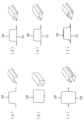
- FIG. 1 is a diagram for explaining a specific example of a cross-sectional shape pattern of a framework member according to an embodiment of the present invention.
- FIG. 2 is a diagram for explaining an example of a process for manufacturing a framework member according to an embodiment of the present invention.
- FIG. 3 is a diagram for explaining the axial crush test method.
- FIG. 4(a) shows a photograph of an example of a fractured portion after an axial crushing test in a comparative example
- FIG. 4(b) shows a photograph of an example of a fractured portion after an axial crushing test in an example of the present invention.
- the skeletal member of the present invention has a cross-sectional shape including a top plate portion extending in the width direction and two vertical wall portions extending from both widthwise ends of the top plate portion in a direction different from the extending direction of the top plate portion.
- the framework member can have various configurations, such as a processed part alone, a combination of a processed part and a flat plate-shaped reinforcing part that reinforces the processed part, or a combination of a plurality of processed parts.
- FIG. 1 Examples of cross-sectional shape patterns are shown in Fig. 1.
- each pattern shown in (a) to (f) shows a cross-sectional shape and a perspective view.
- the cross-sectional shape may not have a closed cross section (see Fig. 1(a)), or may have a closed cross section (see Figs. 1(b) and (c)).
- the processed part 10 or the reinforcing part 11 may have a hole shape or an uneven shape at any location (Fig.
- a specific cross section may be not only a shape extending in the normal direction of the cross section, but also a shape extending along a certain curve or a shape extending while applying a magnification along a certain direction.
- the base steel sheet of the top plate portion has a soft surface layer having a Vickers hardness of 84% or less of the Vickers hardness at a quarter of the plate thickness in a region from the surface to 20 ⁇ m or more in the plate thickness direction and within 0.1 times the plate thickness.
- the soft surface layer means a decarburized layer.
- the soft surface layer contributes to suppressing the propagation of bending cracks during collision deformation, improving the performance as a skeletal member.
- the bendability during press forming is improved.
- the vertical wall portions and the flange portions also have a soft surface layer.
- the Vickers hardness can be measured at a load of 9.8 ⁇ 10 ⁇ 2 N based on JIS Z 2244-1 (2020).
- base steel sheet refers to the steel sheet that serves as the base material in the skeletal member of the present invention.
- the surface of the base steel sheet can be subjected to plating, painting, coating, etc., but plating layers, painting layers, coating layers, etc. are not included in the base steel sheet.
- the surface soft layer has a thickness that satisfies the following formula (1). 20 ⁇ X ⁇ 0.1 ⁇ t-3800 ⁇ [Sb]-1900 ⁇ [Sn]...(1)
- X is the thickness of the surface soft layer ( ⁇ m)
- t is the thickness of the base steel sheet ( ⁇ m)
- [Sb] and [Sn] are the contents (mass%) of Sb and Sn in the base steel sheet, respectively.
- the thickness (X) of the surface soft layer is less than 20 ⁇ m, the desired bendability intended by the present invention cannot be obtained.
- the surface soft layer thickness (X) exceeds (0.1 ⁇ t ⁇ 3800 ⁇ [Sb] ⁇ 1900 ⁇ [Sn]) ⁇ m, it is not possible to achieve both the high strength and the fracture suppression performance during collision that are intended in the present invention. Therefore, the surface soft layer thickness (X) is specified to be 20 ⁇ m or more and (0.1 ⁇ t ⁇ 3800 ⁇ [Sb] ⁇ 1900 ⁇ [Sn]) ⁇ m or less.
- the surface segregation of these elements reduces the allowable upper limit of the soft surface layer thickness (X) that affects bending cracks.
- the upper limit of the soft surface layer that provides good bending properties is (0.1 x t - 3800 x [Sb] - 1900 x [Sn]) ⁇ m.
- the thickness of the surface soft layer is preferably 30 ⁇ m or more, and more preferably 40 ⁇ m or more.
- the thickness of the surface soft layer is preferably 0.1 ⁇ t ⁇ m or less, and more preferably 0.08 ⁇ t ⁇ m or less.
- the base steel sheet in the top plate portion has a tensile strength of 980 MPa or more and 1.8 GPa or less.
- the tensile strength (TS) and yield stress (YS) can be measured by a tensile test in accordance with JIS Z 2241 (2011).
- Ferrite area ratio 60.0% or more
- the surface layer is deformed more than the inside. Therefore, voids are easily formed in the surface layer.
- the area ratio of ferrite 60.0% or more. It is more preferable that the area ratio of ferrite is 80.0% or more, and even more preferable that it is 90.0% or more.
- the area ratio of ferrite may be 100.0%.
- the area ratio of ferrite may be less than 100.0%.
- the area ratio of ferrite may be 98.0% or less, or 96.0% or less.
- This value may be 0.4 or less, or 0.35 or less.
- the lower limit of the value obtained by dividing the area ratio of fresh martensite in the soft surface layer by the total area ratio of bainitic ferrite, fresh martensite, and tempered martensite (excluding retained austenite) is not particularly limited, and may be 0.0. This value may be 0.1 or more, or 0.15 or more.
- the area ratio of retained austenite is preferably 3.0% or less.
- the area ratio of retained austenite is more preferably 2.0% or less, and even more preferably 1.0% or less.
- the lower limit of the area ratio of the retained austenite is not particularly limited, but the area ratio of the retained austenite is preferably 0.1% or more, and more preferably 0.3% or more.
- the area ratio of ferrite is preferably 55.0% or less.
- the area ratio of ferrite is more preferably 45.0% or less, and more preferably 30.0% or less.
- the lower limit of the area ratio of ferrite is not particularly limited and may be 0.0%.
- the area ratio of ferrite may be 1.0% or more, or 2.0% or more.
- Total area ratio of bainitic ferrite and tempered martensite (excluding retained austenite): More than 40.0% Bainitic ferrite and tempered martensite have intermediate hardness between soft ferrite and hard fresh martensite, and are important phases for ensuring good bending properties of the base steel sheet, bending properties of the shear deformation end face, and axial crushing properties. Bainitic ferrite is also a useful phase for obtaining an appropriate amount of retained austenite by utilizing the diffusion of C from bainitic ferrite to untransformed austenite. Tempered martensite is effective for improving TS. Therefore, it is preferable that the total area ratio of bainitic ferrite and tempered martensite (excluding retained austenite): be more than 40.0%.
- the total area ratio of bainitic ferrite and tempered martensite is 65.0% or more, and even more preferable that it is 80.0% or more.
- the upper limit of the total area ratio of bainitic ferrite and tempered martensite may be 100.0%.
- the total area ratio of bainitic ferrite and tempered martensite may be 96.0% or less, or 92.0% or less.
- Bainitic ferrite is upper bainite with little carbide that is formed in a relatively high temperature range.
- the area ratio of fresh martensite 10.0% or less (including 0.0%)
- the area ratio of fresh martensite is preferably 10.0% or less.
- the area ratio of fresh martensite is more preferably 5.0% or less.
- the lower limit of the area ratio of fresh martensite is not particularly limited and may be 0.0%.
- the area ratio of fresh martensite may be 1.0% or more, or 2.0% or more.
- fresh martensite used here refers to as-quenched (untempered) martensite, and also includes islands of fresh martensite (isolated) within ferrite grains.
- the area ratio of retained austenite is less than 3.5%.
- the area ratio of the retained austenite is more preferably 3.0% or less.
- the area ratio of the retained austenite is further preferably 2.5% or less, and even more preferably 2.0% or less.
- the lower limit of the area ratio of the retained austenite is not particularly limited and may be 0%.
- the area ratio of the retained austenite is preferably 0.1% or more, and more preferably 0.2% or more.
- the term "retained austenite" as used herein also includes (isolated) island-like retained austenite within ferrite grains, which will be described later.
- the area ratio of the remaining structure other than the above is preferably 10.0% or less.
- the area ratio of the remaining structure is more preferably 7.0% or less, and even more preferably 5.0% or less.
- the area ratio of the remaining structure may be 0.0%.
- the remaining structure is not particularly limited, and examples include carbides such as pearlite and cementite.
- the type of remaining structure can be confirmed, for example, by observation with a SEM (Scanning Electron Microscope).
- the area ratios of ferrite, bainitic ferrite, tempered martensite and hard second phase (fresh martensite + retained austenite) at the 1/4 sheet thickness position of the base steel sheet are measured as follows. That is, a sample is cut out so that the plate thickness cross section (L cross section) parallel to the longitudinal direction of the base steel sheet becomes the observation surface. The observation surface of the sample is then polished with diamond paste, and then finish-polished with alumina. The observation surface of the sample is then etched with 1 vol. % nital to reveal the structure. Next, the observation position is set to 1/4 of the sheet thickness of the base steel sheet, and five fields of view are observed with a magnification of 3000 times by SEM.
- the field of view to be observed is selected within the range of 1/4 of the sheet thickness of the steel sheet ⁇ 100 ⁇ m, and one field of view is 38 ⁇ m ⁇ 30 ⁇ m.
- the area ratio of each constituent structure ferrite, bainitic ferrite, tempered martensite, and hard second phase (fresh martensite + retained austenite)) divided by the measured area is calculated for five fields of view using Adobe Photoshop of Adobe Systems, and the area ratio of each structure is calculated by averaging these values.
- the zinc plating layer is excluded, and the image is taken so as to include the internal oxide layer.
- Ferrite A black region that is lumpy in shape. It contains almost no carbides. Also, isolated islands of fresh martensite and isolated islands of retained austenite within the ferrite grains are not included in the area ratio of ferrite. Bainitic ferrite: This region is black to dark gray in color and has a blocky or amorphous shape. It also contains a relatively small number of carbides. Tempered martensite: This is a gray area with an amorphous morphology. It also contains a relatively large number of carbides. Hard second phase (retained austenite + fresh martensite): This is a region that is white to light gray in color and has an amorphous morphology. It also does not contain carbides.
- Carbides These are white areas that are dotted or linear in shape and are included in bainite, tempered bainite and tempered martensite.
- Remaining structure The above-mentioned pearlite and cementite are included, and the forms thereof are as known.
- the area ratio of retained austenite is measured as follows.
- the base steel sheet is mechanically ground in the thickness direction (depth direction) to a position of 1/4 of the thickness, and then chemically polished with oxalic acid to obtain an observation surface.
- the observation surface is then observed by X-ray diffraction.
- MoK ⁇ rays are used as the incident X-rays, and the ratio of the diffraction intensity of each of the (200), (220) and (311) faces of fcc iron (austenite) to the diffraction intensity of each of the (200), (211) and (220) faces of bcc iron is obtained, and the volume fraction of the retained austenite is calculated from the ratio of the diffraction intensity of each face.
- the retained austenite is then considered to be three-dimensionally homogeneous, and the volume fraction of the retained austenite is taken as the area fraction of the retained austenite.
- the area ratio of fresh martensite is determined by subtracting the area ratio of retained austenite from the area ratio of the hard second phase determined as described above.
- [Area ratio of fresh martensite (%)] [Area ratio of hard second phase (%)] - [Area ratio of retained austenite (%)]
- the area ratio of the remaining structure is determined by subtracting the area ratio of ferrite, the area ratio of bainitic ferrite, the area ratio of tempered martensite, and the area ratio of the hard second phase determined as described above from 100.0%.
- [Area ratio of remaining structure (%)] 100.0 - [Area ratio of ferrite (%)] - [Area ratio of bainitic ferrite (%)] - [Area ratio of tempered martensite (%)] - [Area ratio of hard second phase (%)]
- the structure of the soft surface layer can be identified at a position halfway through the thickness of the soft surface layer in the same manner as the identification of the structure at a position 1/4 through the thickness of the base steel sheet described above.
- the base steel sheet used for the base material of the present invention preferably has a component composition containing, in mass%, C: 0.050% or more and 0.400% or less, Si: 0.02% or more and 3.00% or less, Mn: 1.50% or more and less than 3.50%, P: 0.001% or more and 0.100% or less, S: 0.0001% or more and 0.0200% or less, Al: 0.005% or more and 2.000% or less, N: 0.0100% or less, Sb: 0.200% or less (including 0%), and Sn: 0.200% or less (including 0%), with the balance being Fe and unavoidable impurities.
- the unit for each component composition is "mass %", but hereinafter, unless otherwise specified, it will be simply indicated as "%".
- C 0.050% or more and 0.400% or less C is an effective element for generating an appropriate amount of tempered martensite, bainite, tempered bainite, etc., to ensure a TS of 980 MPa or more, a high YS, and a high YR.
- the C content is less than 0.050%, the area ratio of ferrite increases, making it difficult to achieve a TS of 980 MPa or more. In addition, this may lead to a decrease in YS and YR.
- the C content exceeds 0.400%, the area ratio of fresh martensite increases excessively, TS becomes excessively high, and El decreases.
- the C content is preferably 0.050% or more and 0.400% or less.
- the C content is more preferably 0.070% or more.
- the C content is further preferably 0.080% or more, and even more preferably 0.090% or more.
- the C content is more preferably 0.300% or less.
- the C content is further preferably 0.280% or less, and even more preferably 0.250% or less.
- Si 0.02% or more and 3.00% or less Si is an element that suppresses excessive softening of tempered martensite. If the Si content is less than 0.02%, the tempered martensite may be excessively softened, making it difficult to ensure a TS of 980 MPa or more. On the other hand, if the Si content exceeds 3.00%, the area ratio of ferrite increases excessively, and the C concentration in austenite during annealing increases excessively, so that the desired bendability of the shear deformed end surface may not be achieved. Therefore, the Si content is preferably 0.02% or more and 3.00% or less. The Si content is more preferably 0.10% or more. The Si content is further preferably 0.20% or more, and even more preferably 0.30% or more. Moreover, the Si content is more preferably 1.80% or less. The Si content is further preferably 1.70% or less, and even more preferably 1.60% or less.
- Mn 1.50% or more and less than 3.50%
- Mn is an element that adjusts the area ratio of bainitic ferrite and tempered martensite. If the Mn content is less than 1.50%, the area ratio of ferrite increases, making it difficult to achieve a TS of 980 MPa or more. In addition, this may result in a decrease in YS and YR.
- Ms point or Ms the martensite transformation start temperature Ms
- the Mn content is preferably 1.50% or more and less than 3.50%.
- the Mn content is more preferably 2.00% or more.
- the Mn content is further preferably 2.20% or more.
- the Mn content is more preferably 3.20% or less.
- the Mn content is further preferably 3.10% or less, and even more preferably 3.00% or less.
- P 0.001% or more and 0.100% or less
- P is an element that has a solid solution strengthening effect and increases the TS and YS of a steel sheet.
- the P content is preferably 0.001% or more.
- the P content is more preferably 0.002% or more, and even more preferably 0.004% or more.
- the P content is more preferably 0.030% or less.
- the P content is more preferably 0.025% or less, and even more preferably 0.020% or less.
- S 0.0001% or more and 0.0200% or less S exists as sulfides in steel.
- the S content is preferably 0.0200% or less.
- the S content is more preferably 0.0080% or less.
- the S content is further preferably 0.0050% or less, and even more preferably 0.0030% or less.
- the S content is preferably 0.0001% or more, more preferably 0.0003% or more, and even more preferably 0.0005% or more.
- Al 0.005% or more and 2.000% or less
- Al promotes ferrite transformation during annealing and in the cooling process after annealing. That is, Al is an element that affects the area ratio of ferrite.
- the Al content is less than 0.005%, the area ratio of ferrite decreases, and ductility may decrease.
- the Al content exceeds 2.000%, the area ratio of ferrite increases excessively, and it may be difficult to make TS 980 MPa or more. In addition, it may also lead to a decrease in YS and YR. Therefore, the Al content is preferably 0.005% or more and 2.000% or less.
- the Al content is more preferably 0.010% or more.
- the Al content is more preferably 0.015% or more.
- the Al content is further preferably 0.020% or more, and even more preferably 0.030% or more.
- the Al content is more preferably 1.000% or less, further preferably 0.800% or less, and further preferably 0.500% or less.
- N 0.0100% or less N exists as nitrides in steel.
- the N content is preferably 0.0100% or less.
- the N content is more preferably 0.0050% or less.
- the N content is further preferably 0.0045% or less, and even more preferably 0.0040% or less.
- the N content is preferably 0.0005% or more, more preferably 0.0010% or more, and further preferably 0.0015% or more.
- Sb 0.200% or less (including 0%)
- Sb is a useful element that can improve plating and chemical conversion treatment properties by segregating on the surface of the base steel sheet during annealing. Therefore, the Sb content may be 0%, but is preferably 0.002% or more. The Sb content is more preferably 0.005% or more. The Sb content is further preferably 0.007% or more, and even more preferably 0.008% or more. On the other hand, if the Sb content exceeds 0.200%, the effect of improving the plating property and chemical conversion property is saturated, and there is a risk of causing a decrease in the bendability and crack propagation resistance inside the steel sheet. Therefore, when Sb is contained, the Sb content is preferably 0.200% or less. The Sb content is more preferably 0.020% or less. The Sb content is further preferably 0.015% or less. The Sb content is even more preferably 0.012% or less. Even more preferably, the Sb content is 0.011% or less.
- Sn 0.200% or less (including 0%)
- Sn is a useful element that segregates on the surface of the base steel sheet during annealing to improve plating and chemical conversion properties. Therefore, the Sn content may be 0%, but is preferably 0.002% or more. The Sn content is more preferably 0.003% or more.
- the Sn content is preferably 0.200% or less.
- the Sn content is more preferably 0.020% or less.
- the Sn content is even more preferably 0.012% or less.
- the Sn content is even more preferably 0.008% or less, and even more preferably 0.004% or less.
- the base steel sheet according to one embodiment of the present invention has a composition that contains the above basic components, with the balance other than the above basic components including Fe (iron) and unavoidable impurities.
- the base steel sheet according to one embodiment of the present invention has a composition that contains the above basic components, with the balance consisting of Fe and unavoidable impurities.
- the base steel sheet according to one embodiment of the present invention may contain at least one selected from the optional components shown below. Note that the effects of the present invention can be obtained so long as the optional components shown below are contained in amounts below the upper limit amounts, so no lower limit is set. Note that when the optional elements listed below are contained in amounts below the preferred lower limit values described below, the elements are considered to be included as unavoidable impurities.
- Nb 0.200% or less, Ti: 0.200% or less, V: 0.200% or less, B: 0.0100% or less, Cr: 1.000% or less, Ni: 1.000% or less, Mo: 1.000% or less , Cu: 1.000% or less, Ta: 0.100% or less, W: 0.500% or less, Mg: 0.0200% or less, Zn: 0.0200% or less, Co: 0.0200% or less, Zr: 0.100 At least one selected from the following: 0% or less, Ca: 0.0200% or less, Se: 0.0200% or less, Te: 0.0200% or less, Ge: 0.0200% or less, As: 0.0500% or less, Sr: 0.0200% or less, Cs: 0.0200% or less, Hf: 0.0200% or less, Pb: 0.0200% or less, Bi: 0.0200% or less, and REM: 0.0200% or less
- Nb 0.200% or less Nb forms fine carbides, nitrides, or carbonitrides during hot rolling or annealing, thereby increasing TS and YS.
- the Nb content is preferably 0.001% or more.
- the Nb content is more preferably 0.005% or more.
- the Nb content exceeds 0.200%, a large amount of coarse precipitates and inclusions may be generated. The coarse precipitates and inclusions may become the starting points of voids and cracks during bending deformation, so it may be difficult to ensure the bendability required for a skeleton member. Therefore, when Nb is contained, the Nb content is preferably 0.200% or less.
- the Nb content is more preferably 0.060% or less.
- Ti 0.200% or less Like Nb, Ti forms fine carbides, nitrides, or carbonitrides during hot rolling or annealing, thereby increasing TS and YS. In order to obtain such an effect, the Ti content is preferably 0.001% or more. The Ti content is more preferably 0.005% or more. On the other hand, if the Ti content exceeds 0.200%, a large amount of coarse precipitates and inclusions may be generated. The coarse precipitates and inclusions may become the starting points of voids and cracks during bending deformation, so it may be difficult to ensure the bendability required for a skeleton member. Therefore, when Ti is contained, the Ti content is preferably 0.200% or less. The Ti content is more preferably 0.060% or less.
- V 0.200% or less
- V forms fine carbides, nitrides, or carbonitrides during hot rolling or annealing, thereby increasing TS and YS.
- the V content is preferably 0.001% or more.
- the V content is more preferably 0.005% or more.
- the V content is further preferably 0.010% or more, and even more preferably 0.030% or more.
- the V content exceeds 0.200%, a large amount of coarse precipitates and inclusions may be generated. The coarse precipitates and inclusions may become the starting points of voids and cracks during bending deformation, so it may be difficult to ensure the bendability required for a skeletal member. Therefore, when V is contained, the V content is preferably 0.200% or less.
- the V content is more preferably 0.060% or less.
- B 0.0100% or less
- B is an element that enhances hardenability by segregating at the austenite grain boundaries.
- B is an element that controls the generation and grain growth of ferrite during cooling after annealing.
- the B content is preferably 0.0001% or more.
- the B content is more preferably 0.0002% or more.
- the B content is further preferably 0.0005% or more, and even more preferably 0.0007% or more.
- the B content exceeds 0.0100%, cracks may occur inside the base steel sheet during hot rolling, which is a manufacturing process for the base steel sheet.
- the B content is preferably 0.0100% or less.
- the B content is more preferably 0.0050% or less.
- Cr 1.000% or less
- Cr is an element that enhances hardenability, so that the addition of Cr produces an appropriate amount of tempered martensite, thereby increasing TS and YS.
- the Cr content is preferably 0.0005% or more.
- the Cr content is more preferably 0.010% or more.
- the Cr content is more preferably 0.030% or more, and even more preferably 0.050% or more.
- the Cr content is more preferably 0.100% or more, and even more preferably 0.150% or more.
- the Cr content exceeds 1.000%, the area ratio of fresh martensite increases, and the bendability (as a skeletal member) decreases, and it may be difficult to ensure the bendability of the base steel sheet end portion in particular. Therefore, when Cr is contained, the Cr content is preferably 1.000% or less.
- the Cr content is more preferably 0.800% or less, and further preferably 0.700% or less.
- Ni 1.000% or less
- Ni is an element that enhances hardenability, so the addition of Ni produces a large amount of tempered martensite, increasing TS and YS.
- the Ni content is 0.005% or more.
- the Ni content is more preferably 0.020% or more.
- the Ni content is further preferably 0.040% or more, and even more preferably 0.060% or more.
- the Ni content exceeds 1.000%, the area ratio of fresh martensite increases, the bendability (as a skeletal member) decreases, and it may be difficult to ensure the bendability of the base steel sheet end in particular. Therefore, when Ni is contained, the Ni content is preferably 1.000% or less.
- the Ni content is more preferably 0.800% or less.
- the Ni content is further preferably 0.600% or less, and even more preferably 0.400% or less.
- Mo 1.000% or less
- Mo is an element that enhances hardenability, so the addition of Mo produces a large amount of tempered martensite, increasing TS and YS.
- the Mo content is more preferably 0.030% or more.
- the Mo content is further preferably 0.100% or more, and even more preferably 0.150% or more.
- the Mo content exceeds 1.000%, the area ratio of fresh martensite increases, the bendability (as a skeletal member) decreases, and it may be difficult to ensure the bendability of the base steel sheet end in particular. Therefore, when Mo is contained, the Mo content is preferably 1.000% or less.
- the Mo content is more preferably 0.500% or less, further preferably 0.450% or less, and even more preferably 0.400% or less.
- the Mo content is more preferably 0.350% or less, and even more preferably 0.300% or less.
- Cu 1.000% or less
- Cu is an element that enhances hardenability, so the addition of Cu produces a large amount of tempered martensite, increasing TS and YS.
- the Cu content is more preferably 0.008% or more, and even more preferably 0.010% or more.
- the Cu content is more preferably 0.020% or more.
- the Cu content is more preferably 0.100% or more, and even more preferably 0.150% or more.
- the area ratio of fresh martensite may increase excessively. Also, a large amount of coarse precipitates and inclusions may be generated.
- the Cu content is preferably 1.000% or less.
- the Cu content is more preferably 0.200% or less.
- Ta 0.100% or less Ta, like Ti, Nb and V, increases TS and YS by forming fine carbides, nitrides or carbonitrides during hot rolling or annealing.
- Ta partially dissolves in Nb carbides or Nb carbonitrides to generate composite precipitates such as (Nb, Ta) (C, N). This suppresses the coarsening of precipitates and stabilizes precipitation strengthening. This further improves TS and YS.
- the Ta content is 0.001% or more. It is more preferable that the Ta content is 0.002% or more, and even more preferable that it is 0.004% or more.
- the Ta content is preferably 0.100% or less.
- the Ta content is more preferably 0.090% or less, and even more preferably 0.080% or less.
- the Ta content is more preferably 0.030% or less, and even more preferably 0.010% or less.
- W 0.500% or less
- W is an element that enhances hardenability, and thus the addition of W produces a large amount of tempered martensite, thereby increasing TS and YS.
- the W content is preferably 0.001% or more.
- the W content is more preferably 0.010% or more, and further preferably 0.030% or more.
- the W content exceeds 0.500%, the area ratio of fresh martensite increases, the bendability (as a skeletal member) decreases, and it may be difficult to ensure the bendability of the base steel sheet end portion in particular. Therefore, when W is contained, the W content is preferably 0.500% or less.
- the W content is more preferably 0.450% or less, and even more preferably 0.400% or less.
- the W content is even more preferably 0.300% or less.
- Mg 0.0200% or less
- Mg is an element that is effective in making the shape of inclusions such as sulfides and oxides spherical and improving the hole expandability and bendability of the base steel sheet.
- the Mg content is 0.0001% or more.
- the Mg content is more preferably 0.0005% or more, and even more preferably 0.0010% or more.
- the Mg content is even more preferably 0.0030% or more.
- the Mg content exceeds 0.0200%, a large amount of coarse precipitates and inclusions may be generated.
- the Mg content is preferably 0.0200% or less.
- the Mg content is more preferably 0.0180% or less, and even more preferably 0.0150% or less.
- the Mg content is even more preferably 0.0100% or less.
- Zn 0.0200% or less
- Zn is an element that is effective in making the shape of inclusions spherical and improving the hole expandability and bendability of the base steel sheet.
- the Zn content is preferably 0.0010% or more.
- the Zn content is more preferably 0.0020% or more, and even more preferably 0.0030% or more.
- the Zn content exceeds 0.0200%, a large amount of coarse precipitates and inclusions may be generated. In such a case, the excessively coarse precipitates and inclusions may become the starting points of voids and cracks during bending deformation, so that it may be difficult to ensure the bendability required for a skeleton member. Therefore, when Zn is contained, the Zn content is preferably 0.0200% or less.
- the Zn content is more preferably 0.0180% or less, and further preferably 0.0150% or less.
- Co is an element that is effective in making the shape of inclusions spheroidal and improving the hole expandability and bendability of the base steel sheet.
- the Co content is preferably 0.0010% or more.
- the Co content is more preferably 0.0020% or more, and even more preferably 0.0030% or more.
- the Co content exceeds 0.0200%, a large amount of coarse precipitates and inclusions may be generated. In such a case, the excessively coarse precipitates and inclusions may become the starting point of voids and cracks during bending deformation, so that it may be difficult to ensure the bendability required for a skeletal member. Therefore, when Co is contained, the Co content is preferably 0.0200% or less.
- the Co content is more preferably 0.0180% or less, and further preferably 0.0150% or less.
- Zr 0.1000% or less
- Zr is an element that is effective in making the shape of inclusions spheroidal and improving the hole expandability and bendability of the base steel sheet.
- the Zr content is preferably 0.0010% or more.
- the Zr content is preferably 0.1000% or less.
- the Zr content is more preferably 0.0300% or less, even more preferably 0.0150% or less, and even more preferably 0.0100% or less.
- Ca 0.0200% or less Ca exists as inclusions in steel.
- the Ca content exceeds 0.0200%, a large amount of coarse inclusions may be generated.
- the excessively coarse precipitates and inclusions may become the starting point of voids and cracks during bending deformation, it may be difficult to ensure the bendability required for a skeletal member. Therefore, when Ca is contained, it is preferable that the Ca content is 0.0200% or less.
- the Ca content is preferably 0.0020% or less.
- the Ca content is more preferably 0.0019% or less, and further preferably 0.0018% or less.
- the lower limit of the Ca content is not particularly limited, but the Ca content is preferably 0.0005% or more.
- the Ca content is more preferably 0.0010% or more.
- Se 0.0200% or less, Te: 0.0200% or less, Ge: 0.0200% or less, As: 0.0500% or less, Sr: 0.0200% or less, Cs: 0.0200% or less, Hf: 0.0200% or less, Pb: 0.0200% or less, Bi: 0.0200% or less, and REM: 0.0200% or less Se, Te, Ge, As, Sr, Cs, Hf, Pb, Bi, and REM are all effective elements for improving the hole expandability and bendability of the base steel sheet. In order to obtain such an effect, it is preferable that the contents of Se, Te, Ge, As, Sr, Cs, Hf, Pb, Bi, and REM are each 0.0001% or more.
- the contents of Se, Te, Ge, As, Sr, Cs, Hf, Pb, Bi and REM are each 0.0200% or less, and the content of As is 0.0500% or less.
- the Se content is more preferably 0.0005% or more, and even more preferably 0.0008% or more.
- the Se content is even more preferably 0.0010% or more, and even more preferably 0.0050% or more.
- the Se content is more preferably 0.0180% or less, and even more preferably 0.0150% or less.
- the Te content is more preferably 0.0005% or more, and even more preferably 0.0008% or more.
- the Te content is even more preferably 0.0010% or more, and even more preferably 0.0050% or more.
- the Te content is more preferably 0.0180% or less, and even more preferably 0.0150% or less.
- the Ge content is more preferably 0.0005% or more, and even more preferably 0.0008% or more.
- the Ge content is more preferably 0.0010% or more, and even more preferably 0.0050% or more.
- the Ge content is more preferably 0.0180% or less, and even more preferably 0.0150% or less.
- the As content is more preferably 0.0010% or more, and even more preferably 0.0015% or more.
- the As content is even more preferably 0.0050% or more.
- the As content is more preferably 0.0400% or less, and even more preferably 0.0300% or less.
- the Sr content is more preferably 0.0005% or more, and even more preferably 0.0008% or more.
- the Sr content is even more preferably 0.0010% or more, and even more preferably 0.0050% or more.
- the Sr content is more preferably 0.0180% or less, and even more preferably 0.0150% or less.
- the Cs content is more preferably 0.0005% or more, and even more preferably 0.0008% or more.
- the Cs content is even more preferably 0.0010% or more, and even more preferably 0.0050% or more.
- the Cs content is more preferably 0.0180% or less, and even more preferably 0.0150% or less.
- the Hf content is more preferably 0.0005% or more, and even more preferably 0.0008% or more.
- the Hf content is even more preferably 0.0010% or more, and even more preferably 0.0050% or more.
- the Hf content is more preferably 0.0180% or less, and even more preferably 0.0150% or less.
- the Pb content is more preferably 0.0005% or more, and even more preferably 0.0008% or more.
- the Pb content is even more preferably 0.0010% or more, and even more preferably 0.0050% or more.
- the Pb content is more preferably 0.0180% or less, and even more preferably 0.0150% or less.
- the Bi content is more preferably 0.0005% or more, and even more preferably 0.0008% or more.
- the Bi content is even more preferably 0.0010% or more, and even more preferably 0.0050% or more.
- the Bi content is more preferably 0.0180% or less, and even more preferably 0.0150% or less.
- the Bi content is even more preferably 0.0100% or less.
- the REM content is more preferably 0.0005% or more, and even more preferably 0.0008% or more.
- the REM content is more preferably 0.0010% or more, and even more preferably 0.0020% or more.
- the REM content is more preferably 0.0180% or less, and even more preferably 0.0150% or less.
- the REM content is even more preferably 0.0100% or less.
- REM refers to scandium (Sc), which has atomic number 21, yttrium (Y), which has atomic number 39, and lanthanoids ranging from lanthanum (La), which has atomic number 57, to lutetium (Lu), which has atomic number 71.
- the REM concentration in the present invention refers to the total content of one or more elements selected from the above-mentioned REMs.
- the REM is not particularly limited, but is preferably Sc, Y, Ce, or La.
- the steel sheet used as the base material for the skeletal member of the present invention may be a cold-rolled steel sheet, which is a base steel sheet, or it may be a hot-dip galvanized steel sheet (GI) in which a plating layer is formed on the base steel sheet, or an alloyed hot-dip galvanized steel sheet (GA).
- GI hot-dip galvanized steel sheet
- GA alloyed hot-dip galvanized steel sheet
- a plating layer is formed on the base steel sheet (on the surface of the base steel sheet), and this plating layer may be provided on only one surface of the base steel sheet, or on both surfaces. That is, in the present invention, a base steel sheet may be provided, and a plating layer (a zinc plating layer, an aluminum plating layer, etc.) may be formed on the base steel sheet.
- the plating layer (zinc plating layer) referred to here refers to a plating layer whose main component is Zn (Zn content is 50.0% or more), and examples of this include a hot-dip galvanized layer and an alloyed hot-dip galvanized layer.
- the hot-dip galvanized layer is composed of, for example, Zn, 20.0 mass% or less of Fe, and 0.001 mass% to 1.0 mass% of Al.
- the hot-dip galvanized layer may optionally contain one or more elements selected from the group consisting of Pb, Sb, Si, Sn, Mg, Mn, Ni, Cr, Co, Ca, Cu, Li, Ti, Be, Bi, and REM in a total amount of 0.0 mass% to 3.5 mass%.
- the Fe content of the hot-dip galvanized layer is more preferably less than 7.0 mass%. The remainder other than the above elements is unavoidable impurities.
- the galvannealed layer is preferably composed of, for example, 20.0% by mass or less Fe and 0.001% by mass or more and 1.0% by mass or less Al.
- the galvannealed layer may optionally contain one or more elements selected from the group consisting of Pb, Sb, Si, Sn, Mg, Mn, Ni, Cr, Co, Ca, Cu, Li, Ti, Be, Bi and REM in a total amount of 0.0% by mass or more and 3.5% by mass or less.
- the Fe content of the galvannealed layer is more preferably 7.0% by mass or more, and even more preferably 8.0% by mass or more.
- the Fe content of the galvannealed layer is more preferably 15.0% by mass or less, and even more preferably 12.0% by mass or less. The remainder other than the above elements is unavoidable impurities.
- the plating weight of the plating layer (zinc plating layer) per side is not particularly limited, but is preferably 20 g/ m2 or more and 80 g/ m2 or less.
- the plating weight of the plating layer is measured as follows. That is, a treatment solution is prepared by adding 0.6 g of a corrosion inhibitor for Fe (Ivit 700BK (registered trademark) manufactured by Asahi Chemical Industry Co., Ltd.) to 1 L of a 10 mass% aqueous hydrochloric acid solution. Next, a steel sheet (galvanized steel sheet) to be used as a test material is immersed in the treatment solution to dissolve the plating layer (galvanized layer). The mass loss of the test material before and after dissolution is then measured, and the value is divided by the surface area of the base steel sheet (the surface area of the part that was covered with plating) to calculate the plating coverage (g/ m2 ).
- a corrosion inhibitor for Fe Ivit 700BK (registered trademark) manufactured by Asahi Chemical Industry Co., Ltd.
- the thickness of the steel plate according to one embodiment of the present invention is not particularly limited, but is preferably 0.5 mm or more. More preferably, it is 0.6 mm or more. Even more preferably, it is 0.8 mm or more. Furthermore, the thickness of the steel plate is preferably 2.3 mm or less. More preferably, it is 1.6 mm or less.
- R limit bending radius
- t plate thickness measured by a 90-degree V-bend test conforming to JIS Z 2248 (2022) is 2.0 or less.
- Excellent bendability means excellent fracture resistance characteristics during collision deformation.
- the method for producing a steel sheet used as a base material of the present invention includes a hot rolling step of hot rolling a steel slab to obtain a hot rolled steel sheet, a pickling step of pickling the hot rolled steel sheet, a cold rolling step of cold rolling, an annealing step of annealing the steel sheet after the cold rolling step, a cooling step of cooling the steel sheet, and a plating step of galvanizing the steel sheet as necessary.
- the galvanizing step include hot dip galvanizing and galvannealing.
- the method for producing a base steel sheet of the present invention includes a hot rolling step of hot rolling a steel slab having the above-mentioned component composition under a finish rolling temperature of 820°C or higher, and an annealing step of heating the steel sheet after the hot rolling step and annealing it under conditions of an annealing temperature of 750°C to 900°C, a soaking time of 20 seconds or longer, and an atmosphere with a dew point of -10°C or higher, and further satisfying formulas (2) and (3).
- T is the annealing temperature (° C.)
- t1 is the time (s) from 650° C. to the annealing temperature T during temperature increase in the annealing step
- t2 is the soaking time (s)
- [%C] is the C content of the steel plate
- [%Si] is the Si content of the steel plate
- [%Mn] is the Mn content of the steel plate.
- the method of smelting the steel material is not particularly limited, and any known smelting method such as converter or electric furnace is suitable.
- any known smelting method such as converter or electric furnace is suitable.
- energy-saving processes such as direct rolling and direct rolling, in which the steel slab is not cooled to room temperature but is still loaded into the heating furnace, or is rolled immediately after a short period of heat retention, can also be applied without any problems.
- the slab heating temperature is preferably 1100° C. or higher from the viewpoint of dissolving carbides and reducing the rolling load.
- the slab heating temperature is preferably 1300° C. or lower.
- the slab heating temperature is the temperature of the slab surface.
- the slab is made into a sheet bar by rough rolling under normal conditions, but when the heating temperature is low, it is preferable to heat the sheet bar using a bar heater or the like before finish rolling from the viewpoint of preventing trouble during hot rolling.
- Finish rolling temperature 820°C or higher.
- a low finish rolling temperature leads to an increase in the rolling load.
- a low finish rolling temperature increases the rolling reduction rate in the unrecrystallized state of austenite, causing abnormal structures elongated in the rolling direction to develop, reducing the ductility, hole expandability, and bendability of the final material.
- the finish rolling temperature is set to 820°C or higher.
- the finish rolling temperature is preferably 830°C or higher, more preferably 850°C or higher.
- the finish rolling temperature is preferably 1080°C or lower, more preferably 1050°C or lower.
- the coiling temperature after hot rolling is not particularly limited, but consideration must be given to the possibility of reducing the ductility, hole expandability, and bendability of the final material. For this reason, it is preferable that the coiling temperature after hot rolling be 300°C or higher. It is also preferable that the coiling temperature after hot rolling be 700°C or lower.
- the rough-rolled sheets may be joined together and continuously finished.
- the rough-rolled sheets may also be wound up once.
- some or all of the finish rolling may be performed as lubricated rolling. Performing lubricated rolling is also effective from the standpoint of uniforming the shape of the steel sheet and the material. Note that the friction coefficient during lubricated rolling is preferably in the range of 0.10 to 0.25.
- the hot-rolled steel sheet produced as described above may be subjected to pickling.
- Pickling can remove oxides from the steel sheet surface, and therefore can be performed to ensure good chemical conversion treatability and plating quality in the final high-strength steel sheet product.
- Pickling may be performed once or multiple times.
- the hot-rolled pickled sheet or hot-rolled steel sheet obtained as described above is subjected to cold rolling as necessary.
- the pickled sheet may be subjected to cold rolling as it is after hot rolling, or may be subjected to cold rolling after heat treatment.
- the cold-rolled steel sheet obtained after cold rolling may be subjected to pickling.
- the cold rolling is carried out by multi-pass rolling requiring two or more passes, such as tandem multi-stand rolling or reverse rolling.
- the cold rolling reduction ratio is 20% or more and 80% or less.
- the cold rolling reduction ratio (cumulative reduction ratio) is not particularly limited, but is preferably 20% or more and 80% or less. If the cold rolling reduction ratio is less than 20%, the steel structure is likely to become coarse and non-uniform in the annealing process, and the TS and bendability of the final product may be reduced. On the other hand, if the cold rolling reduction ratio exceeds 80%, the shape of the steel sheet is likely to be defective, and when zinc plating is performed in the subsequent process, the amount of zinc plating may be non-uniform.
- annular process In one embodiment of the present invention, it is preferable to raise the temperature of the steel sheet after the hot rolling process (when cold rolling is not performed) or after the cold rolling process (when cold rolling is performed), and anneal the steel sheet under the conditions of an annealing temperature of 750° C. or more and 900° C. or less, a soaking time of 20 seconds or more, and an atmosphere with a dew point of ⁇ 10° C. or more, and further under the conditions that satisfy formula (2) and formula (3).
- T is the annealing temperature (° C.)
- t1 is the time (s) from 650° C. to the annealing temperature T during the temperature rise in the annealing process
- t2 is the soaking time (s).
- Annealing temperature 750° C. to 900° C. If the annealing temperature is less than 750° C., the ratio of austenite generated during heating in the two-phase region of ferrite and austenite becomes insufficient, and the area ratio of ferrite increases excessively after annealing, making it impossible to obtain the desired TS and YS. On the other hand, if the annealing temperature exceeds 900° C., the ductility decreases. Therefore, the annealing temperature is preferably 750° C. or higher and 900° C. or lower. The annealing temperature is more preferably 880° C. or lower. The annealing temperature is even more preferably 870° C. or lower. The annealing temperature is more preferably 780° C. or higher, and even more preferably 800° C. or higher. The annealing temperature is the maximum temperature (soaking temperature) reached in the annealing process.
- the soaking time is preferably 20 seconds or more.
- the soaking time is more preferably 30 seconds or more, and more preferably 50 seconds or more.
- the upper limit of the soaking time is not particularly limited, the soaking time is preferably 900 seconds or less, and more preferably 800 seconds or less.
- the annealing time is even more preferably 600 seconds or less, and even more preferably 250 seconds or less.
- the soaking time is a holding time in a temperature range of (annealing temperature -40°C) or more and (annealing temperature) or less.
- the soaking time includes not only the holding time at the annealing temperature, but also the residence time in a temperature range of (annealing temperature -40°C) or more and (annealing temperature) or less during heating and cooling before and after reaching the annealing temperature.
- the number of annealing steps may be two or more, but is preferably one from the viewpoint of energy efficiency.
- Dew point of the atmosphere in the annealing step -10°C or higher
- the dew point of the atmosphere in the annealing step is preferably -10°C or higher.
- the dew point of the annealing atmosphere in the annealing step is more preferably -5°C or higher, even more preferably 0°C or higher, and most preferably +5°C or higher.
- the dew point of the annealing atmosphere in the annealing step is preferably 30°C or lower.
- the dew point of the annealing atmosphere in the annealing step is more preferably 25°C or lower, and even more preferably 20°C or lower.
- T is the annealing temperature (° C.)
- t1 is the time (s) from 650° C. to the annealing temperature T during the temperature rise in the annealing process
- t2 is the soaking time (s).
- t1 is the time (s) from 650° C. to the annealing temperature (soaking temperature) T during the temperature rise in the annealing process
- t2 is the soaking time (holding time) (s) in the annealing process
- Ac1 is the Ac1 point (° C.).
- Y in formula (3) is set to be 2400 or more and 20000 or less.
- Y is more preferably 9000 or more, and further preferably 12000 or more.
- Y is more preferably 19000 or less, and further preferably 18000 or less.
- t1 is 30 s or more. Also, it is preferable that t1 is 80 s or less.
- [%C] is the C content in the steel plate
- [%Si] is the Si content in the steel plate
- [%Mn] is the Mn content in the steel plate.
- the steel sheet after the annealing step is preferably cooled to a cooling stop temperature of less than 100°C.
- the cooling start temperature can be set to 750°C or higher and 900°C or lower.
- the cooling stop temperature is more preferably 80° C. or lower, and even more preferably 60° C. or lower.
- the cooling stop temperature is more preferably 5°C or higher, and even more preferably 15°C or higher.
- the average cooling rate during this cooling step is preferably 10° C./s or more and 50° C./s or less.
- This cooling step makes it possible to obtain the steel structure specified in the present invention.
- the dew point of the atmosphere in this cooling step is preferably -20°C or less. If the dew point of the atmosphere exceeds -20°C, the thickness of the soft surface layer in the in-plane direction of the steel sheet becomes more uneven, and the tensile strength specified in the present invention may not be obtained. Therefore, the dew point of the atmosphere in this cooling step is preferably -20°C or less.
- the above average cooling rate (° C./s) is obtained by dividing the difference between the cooling start temperature (° C.) and the cooling end temperature (° C.) in the cooling step by the cooling time (s).
- first holding process (reheating holding process)
- reheating holding step it is preferable to reheat the steel sheet to a reheating holding temperature range of not less than the cooling stop temperature and not more than 440° C., and hold the temperature for not less than 10 seconds.
- the reheating holding temperature range is more preferably 420°C or less, and even more preferably 400°C or less.
- the retention time is more preferably 20 seconds or more, and further preferably 30 seconds or more.
- the retention time is more preferably 100 seconds or less, and further preferably 80 seconds or less.
- the surface strain introducing step it is preferable to impart a tension of 19.6 N/ mm2 or more to the steel sheet after the above-mentioned first holding step in the reheating holding temperature range.
- the load cells must be arranged parallel to the tension direction.
- the load cells are preferably disposed at positions 200 mm from both ends of the roll, and the body length of the roll used is preferably 1500 to 2500 mm.
- this tension is preferably 21.5 N/ mm2 or more, and more preferably 23.5 N/ mm2 or more. Moreover, this tension is preferably 147 N/ mm2 or less, and more preferably 98 N/ mm2 or less. This tension is even more preferably 39.2 N/ mm2 or less.
- the steel sheet after the surface layer strain introduction step is preferably held in the reheating holding temperature range for 10 seconds or more.
- the holding time in the second holding step is more preferably 15 seconds or more, and even more preferably 20 seconds or more.
- the holding time is preferably 60 seconds or less, and more preferably 50 seconds or less.
- the steel sheet is subjected to a zinc plating treatment in the plating step, thereby obtaining a zinc-plated steel sheet.
- the galvanizing treatment include hot-dip galvanizing treatment and hot-dip galvannealing treatment.
- hot-dip galvanizing it is preferable to immerse the steel sheet in a zinc plating bath at 440°C to 500°C, and then adjust the coating weight by gas wiping or the like.
- a plating bath with an Al content of 0.10 mass% to 0.23 mass%, with the balance being Zn and unavoidable impurities.
- alloying hot-dip galvanizing treatment it is preferable to carry out the hot-dip galvanizing treatment as described above, and then to carry out alloying treatment by heating the hot-dip galvanized steel sheet to an alloying temperature of 450° C. or more and 600° C. or less. If the alloying temperature is less than 450°C, the Zn-Fe alloying rate is slow, and alloying may be difficult. On the other hand, if the alloying temperature exceeds 600°C, untransformed austenite is transformed into pearlite, making it difficult to achieve a TS of 980 MPa or more.
- the alloying temperature is more preferably 500°C or more, and further preferably 510°C or more.
- the alloying temperature is more preferably 570°C or less.
- the coating weight of both the hot-dip galvanized steel sheet (GI) and the galvannealed steel sheet (GA) is preferably 20 to 80 g/ m2 per side.
- the coating weight can be adjusted by gas wiping or the like.
- the steel sheet obtained as described above may be further subjected to temper rolling. If the reduction rate of temper rolling exceeds 2.00%, the yield stress increases, and the dimensional accuracy when the steel sheet is formed into a component may decrease. Therefore, the reduction rate of temper rolling is preferably 2.00% or less.
- the lower limit of the reduction rate of temper rolling is not particularly limited, but it is preferably 0.05% or more from the viewpoint of productivity.
- Temper rolling may be performed on a device connected to the annealing device for performing each of the above-mentioned processes (online), or on a device not connected to the annealing device for performing each of the processes (offline).
- the number of rolling times of temper rolling may be one or more than two. As long as the same elongation rate as that of temper rolling can be imparted, rolling using a leveler or the like may be used.
- Other manufacturing method conditions are not particularly limited, but from the viewpoint of productivity, it is preferable to carry out the above-mentioned series of processes such as annealing, hot-dip galvanizing, and alloying of zinc plating in a continuous galvanizing line (CGL). After hot-dip galvanizing, wiping is possible to adjust the coating weight. Note that plating conditions other than those mentioned above can be based on standard hot-dip galvanizing methods.
- FIG. 2 shows an example of a process for manufacturing a skeletal member using a steel plate having a base steel plate as a base material.
- the skeletal member 1 may have a hat-shaped part (processed part 10) consisting of a top plate part, a vertical wall part, and a flange part, and a back plate part (reinforcement part 11).
- the hat-shaped part shown in FIG. 2(a) is processed by a normal forming method for thin plate material such as press forming, bending, roll forming, and extrusion forming. As shown in FIG.
- the hat-shaped part (processed part 10) and the back plate part (reinforcement part 11) are processed into an integrated part (skeletal member 1) by assembling them by a joining method such as spot welding (see symbol A in the figure), laser welding, bolt fastening, adhesive joining, or crimping.
- a joining method such as spot welding (see symbol A in the figure), laser welding, bolt fastening, adhesive joining, or crimping.
- an end fixing jig 12 is further attached to an integrated part (skeleton member 1) having a hat-shaped part and a back plate part to obtain a hollow cross-sectional part 13.
- 40 mm, 40 mm, and 20 mm shown in Fig. 2(a) are examples of the lengths of the top plate part, vertical wall part, and flange part in the cross-sectional shape, respectively, but the lengths of the top plate part, vertical wall part, and flange part are not limited to these lengths.
- the back plate part is joined to the hat-shaped part to form a closed cross section, which prevents the cross section of the hat-shaped part from opening, and is a reinforcing member for stably subjecting the skeletal member to large deformation.
- this back plate part for example, cold-rolled steel sheet or galvanized steel sheet can be used.
- the back plate part be a steel sheet with a tensile strength of 590 MPa or more.
- the above shows an example in which the base steel sheet is treated in the annealing process, cooling process, first holding process, surface strain introduction process, and second holding process while it is still in the steel sheet state.
- the heat treatment processes from the annealing process to the second holding process do not necessarily have to be performed while the base steel sheet is in the steel sheet state.
- the heat treatment processes from the annealing process to the second holding process may be performed after the base steel sheet is press-formed into the shape of a skeletal member.
- the skeletal member of the present invention has excellent collision characteristics, particularly when used as a skeletal member for an automobile, but the use is not limited to this.
- the skeletal member of the present invention can be used as a skeletal member for architectural structures or mechanical structures.
- a strength member such as a pillar or beam for an architectural structure
- it can be a strong skeletal member with excellent impact resistance in the event of an earthquake.
- a skeletal member for a mechanical structure it can be a strong skeletal member with excellent impact resistance when some kind of impact load is applied to the mechanical structure.
- ⁇ Steel sheet manufacturing method> A slab having the chemical composition shown in Table 1 was manufactured by melting in a converter and continuous casting. The steel slab was heated to 1200°C, and after heating, the steel slab was subjected to hot rolling consisting of rough rolling and finish rolling at a finish rolling temperature of 900°C to obtain a hot-rolled steel sheet. The obtained hot-rolled steel sheet was then pickled and cold-rolled at a cold rolling reduction rate of 30 to 60% to obtain a cold-rolled steel sheet having a thickness of 1.6 mm. The obtained cold-rolled steel sheet was then subjected to annealing and cooling. In addition, some of the steel sheets were subjected to hot-dip galvanizing or alloyed hot-dip galvanizing.
- Table 2 shows the conditions in the annealing process, the cooling process, the plating process during the cooling process, the reheating and holding process (first holding process), the surface layer strain introduction process, and the second holding process.
- the type of plating process GA is a condition in which alloyed hot-dip galvanizing treatment was performed
- GI is a condition in which hot-dip galvanizing treatment was performed
- CR is a condition in which the base steel sheet was not subjected to plating treatment.
- a blank for use as a hat-shaped frame member was cut out from the above steel plate. That is, materials were prepared so that the hat-shaped member would have a constant cross section with an axial length of 200 mm after molding, and the hat-shaped member was produced by press molding.
- the cross-sectional shape of the hat-shaped member is shown in Figure 2.
- the length of the top plate and vertical wall was 40 mm
- the length of the flange was 20 mm
- all bending ridges connecting the top plate and vertical wall and the vertical wall and flange were molded to have an inner bending radius of 5 mm.
- This back plate member is a cold-rolled steel plate with a thickness of 1.6 mm and a tensile strength of 1,180 MPa, and is a reinforcing member that is joined to the hat-shaped part to form a closed cross-section, thereby suppressing the opening of the cross-section of the hat-shaped part in the axial crushing test described below, thereby effectively and stably causing large deformation.
- a jig for fixing the end cross section was joined by arc welding to one end of the frame member in the axial direction of the test body.
- the method for measuring the surface soft layer is as follows. A steel plate test piece was cut out from the top plate of the hat-shaped skeletal member, and the plate thickness cross section (L cross section) perpendicular to the longitudinal direction of the hat-shaped skeletal member was smoothed by wet polishing. Then, using a Vickers hardness tester, measurements were performed at 1 ⁇ m intervals from a position 1 ⁇ m in the plate thickness direction from the surface of the steel plate test piece to a position 120 ⁇ m in the plate thickness direction with a load of 9.8 ⁇ 10 ⁇ 2 N. Thereafter, measurements were performed at 20 ⁇ m intervals to the center of the plate thickness. The region where the hardness was reduced to 84% or less compared to the hardness at the 1/4 position of the plate thickness was defined as the soft layer (surface soft layer), and the thickness of the region in the plate thickness direction was defined as the thickness of the soft layer.
- ⁇ Tissue measurement method> The structure at the position of 1/2 the thickness of the surface soft layer and the structure at the position of 1/4 the sheet thickness of the base steel sheet were measured by the method described above.
- ⁇ Tensile test> The tensile test was performed in accordance with JIS Z 2241 (2011). That is, a JIS No. 5 test piece was taken from the top plate of the hat-shaped frame member. Using the taken test piece, a tensile test was performed at a crosshead speed of 10 mm/min to measure TS and YS.
- V (90°) bending test was performed in accordance with JIS Z 2248 (2022). A test piece measuring 100 mm x 35 mm was taken from the top plate of the hat-shaped frame member by shearing and end grinding. Bend radius R: Varies in increments of 0.1 to 0.5 mm Test method: Die support, punch press molding load: 10 tons Test speed: 30 mm/min Holding time: 5 s Bending direction: transverse to rolling (C) direction Evaluation was performed three times, and the minimum bending radius (critical bending radius) R at which cracks did not appear was divided by the thickness t of the base steel sheet to calculate R/t. In addition, using a Leica stereo microscope, cracks with a length of 200 ⁇ m or more at 25x magnification were determined to be cracks.
- ⁇ Axial crush test> 3 is a diagram for explaining an axial crush test method carried out to evaluate the collision performance of a frame part (hollow cross-section part) 13 produced based on this embodiment.
- the axial crush test was carried out using an autograph bending tester.
- the end fixing jig 12 was installed on the flat floor surface of the non-movable part 20 of the bending tester so that the axial direction of the test piece was the moving direction of the bending tester.
- a punch 22 having a flat surface was attached to the moving part 21 of the bending tester so that the flat surface of the punch 22 was perpendicular to the moving direction of the tester (see symbol X in FIG. 3), and the test piece (hollow cross-section part 13) was crushed by moving the moving part 21 of the bending tester.
- the punch moving speed was 10 mm/min, and the punch moving stroke was 100 mm.
- the test was performed on three members using each material. The load on the punch during the crushing test was measured, and the maximum load value at the time of initial buckling was taken. The average value of the three members was calculated and used as the maximum load N3 average. Regarding the pass/fail of the maximum load N3 average, a value of 220 kN or more was judged as good, and a value of less than 220 kN was judged as bad.
- Figure 4 shows examples of fractured parts after the axial crush test of frame parts using the materials of Experiment No. 10 (Comparative Example) and Experiment No. 3 (Example of the present invention).
- the fracture shown in FIG. 4 is a fracture of the base material (steel plate itself) by bending.
- the fracture form is confirmed in which the fracture progresses through the base material and becomes a large crack
- the fracture form is confirmed in which the base material is bent and broken but the crack is limited to a partial crack at the bending deformation part.
- the arrow shown in FIG. 4(a) indicates the position where the large crack occurs in the base material
- the arrow shown in FIG. 4(b) indicates the position where the small crack occurs in the base material.
- the fracture part with a fracture length of 20 mm or more was judged to be a large crack
- the fracture part with a fracture length of less than 20 mm was judged to be a small crack
- the number of each fracture part was measured.
- the above fracture judgment and quantity measurement were performed for all three bodies, and the total value was calculated, and this total value was taken as the total number of fractures.
- the body with one or more large cracks or five or more small cracks was judged to be poor, and the rest was judged to be good.
- Nos. 5 to 9, 11, and 13 are comparative examples in which the tensile strength of the base steel sheet of the top plate portion is less than 980 MPa.
- Comparative Examples No. 9, 10, and 52 since the soft surface layer was thin, the R/t value in the bending test was large, and large cracks occurred in two or more places in the axial crushing test.
- the total number of breaks is less than those in Comparative Example No. 9, Comparative Example No. 10, and Comparative Example No. 52, and the bending break resistance property of the base material during a collision is excellent. Also, it can be seen that the present invention example shows a high maximum load value due to a high YS compared to Comparative Example Nos. 5 to 9, 11, and 13.
- the thickness of the surface soft layer was thick, and R/t was 1.5 or less, which was particularly excellent in bending properties, so the total number of fractures was suppressed to 2 or less minor cracks, and it can be seen that the bending fracture resistance properties were further excellent.
- R/t was 1.5 or less, which was particularly excellent in bending properties, so the total number of fractures was suppressed to 2 or less minor cracks, and it can be seen that the bending fracture resistance properties were further excellent.
Landscapes
- Chemical & Material Sciences (AREA)
- Engineering & Computer Science (AREA)
- Materials Engineering (AREA)
- Mechanical Engineering (AREA)
- Metallurgy (AREA)
- Organic Chemistry (AREA)
- Heat Treatment Of Sheet Steel (AREA)
Priority Applications (2)
| Application Number | Priority Date | Filing Date | Title |
|---|---|---|---|
| JP2025505541A JPWO2025075096A1 (https=) | 2023-10-04 | 2024-10-03 | |
| CN202480062706.2A CN121941786A (zh) | 2023-10-04 | 2024-10-03 | 骨架构件 |
Applications Claiming Priority (2)
| Application Number | Priority Date | Filing Date | Title |
|---|---|---|---|
| JP2023-172601 | 2023-10-04 | ||
| JP2023172601 | 2023-10-04 |
Publications (1)
| Publication Number | Publication Date |
|---|---|
| WO2025075096A1 true WO2025075096A1 (ja) | 2025-04-10 |
Family
ID=95283400
Family Applications (1)
| Application Number | Title | Priority Date | Filing Date |
|---|---|---|---|
| PCT/JP2024/035465 Pending WO2025075096A1 (ja) | 2023-10-04 | 2024-10-03 | 骨格部材 |
Country Status (3)
| Country | Link |
|---|---|
| JP (1) | JPWO2025075096A1 (https=) |
| CN (1) | CN121941786A (https=) |
| WO (1) | WO2025075096A1 (https=) |
Citations (7)
| Publication number | Priority date | Publication date | Assignee | Title |
|---|---|---|---|---|
| JP2017002384A (ja) * | 2015-06-15 | 2017-01-05 | 新日鐵住金株式会社 | 耐スポット溶接部破断特性に優れた鋼板及びその製造方法 |
| WO2018151322A1 (ja) | 2017-02-20 | 2018-08-23 | 新日鐵住金株式会社 | 高強度鋼板 |
| WO2019116531A1 (ja) | 2017-12-15 | 2019-06-20 | 日本製鉄株式会社 | 鋼板、溶融亜鉛めっき鋼板および合金化溶融亜鉛めっき鋼板 |
| WO2019187027A1 (ja) | 2018-03-30 | 2019-10-03 | 日本製鉄株式会社 | 合金化溶融亜鉛めっき鋼板 |
| WO2021200580A1 (ja) * | 2020-03-31 | 2021-10-07 | Jfeスチール株式会社 | 鋼板、部材及びそれらの製造方法 |
| WO2022136686A1 (en) * | 2020-12-23 | 2022-06-30 | Voestalpine Stahl Gmbh | A zinc or zinc-alloy coated strip or steel with improved zinc adhesion |
| WO2023026819A1 (ja) * | 2021-08-24 | 2023-03-02 | Jfeスチール株式会社 | 高強度鋼板およびその製造方法 |
-
2024
- 2024-10-03 JP JP2025505541A patent/JPWO2025075096A1/ja active Pending
- 2024-10-03 CN CN202480062706.2A patent/CN121941786A/zh active Pending
- 2024-10-03 WO PCT/JP2024/035465 patent/WO2025075096A1/ja active Pending
Patent Citations (7)
| Publication number | Priority date | Publication date | Assignee | Title |
|---|---|---|---|---|
| JP2017002384A (ja) * | 2015-06-15 | 2017-01-05 | 新日鐵住金株式会社 | 耐スポット溶接部破断特性に優れた鋼板及びその製造方法 |
| WO2018151322A1 (ja) | 2017-02-20 | 2018-08-23 | 新日鐵住金株式会社 | 高強度鋼板 |
| WO2019116531A1 (ja) | 2017-12-15 | 2019-06-20 | 日本製鉄株式会社 | 鋼板、溶融亜鉛めっき鋼板および合金化溶融亜鉛めっき鋼板 |
| WO2019187027A1 (ja) | 2018-03-30 | 2019-10-03 | 日本製鉄株式会社 | 合金化溶融亜鉛めっき鋼板 |
| WO2021200580A1 (ja) * | 2020-03-31 | 2021-10-07 | Jfeスチール株式会社 | 鋼板、部材及びそれらの製造方法 |
| WO2022136686A1 (en) * | 2020-12-23 | 2022-06-30 | Voestalpine Stahl Gmbh | A zinc or zinc-alloy coated strip or steel with improved zinc adhesion |
| WO2023026819A1 (ja) * | 2021-08-24 | 2023-03-02 | Jfeスチール株式会社 | 高強度鋼板およびその製造方法 |
Non-Patent Citations (2)
| Title |
|---|
| "文献4には、脱炭層を有するマルテンサイト冷延鋼板(CRM1500)において、脱炭層深さが深くなることで曲げ角 度()が増大することが示されている", 1 January 2022 (2022-01-01), pages 53 - 54 |
| KOMINE, TRANSACTIONS OF THE SOCIETY OF AUTOMOTIVE ENGINEERS OF JAPAN, vol. 52, no. 1, 2021, pages 94 - 99 |
Also Published As
| Publication number | Publication date |
|---|---|
| JPWO2025075096A1 (https=) | 2025-04-10 |
| CN121941786A (zh) | 2026-04-28 |
Similar Documents
| Publication | Publication Date | Title |
|---|---|---|
| US12435384B2 (en) | High-strength steel sheet and method for manufacturing same | |
| JP7601257B2 (ja) | 鋼板、部材およびそれらの製造方法 | |
| JP6787535B1 (ja) | 高強度鋼板およびその製造方法 | |
| JP7197063B1 (ja) | 亜鉛めっき鋼板および部材、ならびに、それらの製造方法 | |
| KR20250004713A (ko) | 강판, 부재 및 그들의 제조 방법 | |
| WO2023026819A1 (ja) | 高強度鋼板およびその製造方法 | |
| JP7537634B2 (ja) | 鋼板、部材およびそれらの製造方法 | |
| WO2023007833A1 (ja) | 亜鉛めっき鋼板および部材、ならびに、それらの製造方法 | |
| KR20240075851A (ko) | 아연 도금 강판 및 부재, 그리고, 그것들의 제조 방법 | |
| JP7197062B1 (ja) | 亜鉛めっき鋼板および部材、ならびに、それらの製造方法 | |
| JP7176666B1 (ja) | クラッド鋼板および部材、ならびに、それらの製造方法 | |
| JP7601256B2 (ja) | 鋼板、部材およびそれらの製造方法 | |
| WO2023188539A1 (ja) | 鋼板、部材およびそれらの製造方法 | |
| WO2024116396A1 (ja) | 溶融亜鉛めっき鋼板、溶融亜鉛めっき鋼板を用いてなる部材、部材からなる自動車の骨格構造部品用又は自動車の補強部品、ならびに溶融亜鉛めっき鋼板及び部材の製造方法 | |
| WO2025075096A1 (ja) | 骨格部材 | |
| JP7740597B2 (ja) | 鋼板、部材およびそれらの製造方法 | |
| JP7616491B1 (ja) | 鋼板、部材およびそれらの製造方法 | |
| JP7616490B1 (ja) | 鋼板、部材およびそれらの製造方法 | |
| JP7711775B2 (ja) | 溶融亜鉛めっき鋼板、溶融亜鉛めっき鋼板を用いてなる部材、部材からなる自動車の骨格構造部品又は自動車の補強部品、ならびに溶融亜鉛めっき鋼板及び部材の製造方法 | |
| JP7740596B2 (ja) | 鋼板、部材およびそれらの製造方法 | |
| KR20260053568A (ko) | 골격 부재 | |
| WO2026070022A1 (ja) | 鋼板及び部材、並びに、それらの製造方法 | |
| WO2026070019A1 (ja) | 鋼板及び部材、並びに、それらの製造方法 | |
| KR20260053079A (ko) | 강판, 부재 및 그들의 제조 방법 | |
| EP4696802A1 (en) | High-strength steel plate, high-strength plated steel plate, methods for manufacturing same, and member |
Legal Events
| Date | Code | Title | Description |
|---|---|---|---|
| ENP | Entry into the national phase |
Ref document number: 2025505541 Country of ref document: JP Kind code of ref document: A |
|
| WWE | Wipo information: entry into national phase |
Ref document number: 2025505541 Country of ref document: JP |
|
| 121 | Ep: the epo has been informed by wipo that ep was designated in this application |
Ref document number: 24874696 Country of ref document: EP Kind code of ref document: A1 |
|
| WWE | Wipo information: entry into national phase |
Ref document number: 2024874696 Country of ref document: EP |
|
| WWE | Wipo information: entry into national phase |
Ref document number: 2601002227 Country of ref document: TH |