WO2025069595A1 - 作業機械 - Google Patents
作業機械 Download PDFInfo
- Publication number
- WO2025069595A1 WO2025069595A1 PCT/JP2024/021802 JP2024021802W WO2025069595A1 WO 2025069595 A1 WO2025069595 A1 WO 2025069595A1 JP 2024021802 W JP2024021802 W JP 2024021802W WO 2025069595 A1 WO2025069595 A1 WO 2025069595A1
- Authority
- WO
- WIPO (PCT)
- Prior art keywords
- target
- excavation
- bucket
- work machine
- calculation unit
- Prior art date
- Legal status (The legal status is an assumption and is not a legal conclusion. Google has not performed a legal analysis and makes no representation as to the accuracy of the status listed.)
- Pending
Links
Images









Classifications
-
- E—FIXED CONSTRUCTIONS
- E02—HYDRAULIC ENGINEERING; FOUNDATIONS; SOIL SHIFTING
- E02F—DREDGING; SOIL-SHIFTING
- E02F3/00—Dredgers; Soil-shifting machines
- E02F3/04—Dredgers; Soil-shifting machines mechanically-driven
- E02F3/28—Dredgers; Soil-shifting machines mechanically-driven with digging tools mounted on a dipper- or bucket-arm, i.e. there is either one arm or a pair of arms, e.g. dippers, buckets
- E02F3/36—Component parts
- E02F3/42—Drives for dippers, buckets, dipper-arms or bucket-arms
- E02F3/43—Control of dipper or bucket position; Control of sequence of drive operations
-
- E—FIXED CONSTRUCTIONS
- E02—HYDRAULIC ENGINEERING; FOUNDATIONS; SOIL SHIFTING
- E02F—DREDGING; SOIL-SHIFTING
- E02F9/00—Component parts of dredgers or soil-shifting machines, not restricted to one of the kinds covered by groups E02F3/00 - E02F7/00
- E02F9/20—Drives; Control devices
Definitions
- the present invention relates to a work machine equipped with a work implement.
- Patent Document 1 proposes a control device that plans a target path for a work implement (hereinafter also referred to as a work device or bucket) equipped on a work machine according to a predetermined excavation curve ratio, and controls the work implement along the target path.
- a work implement hereinafter also referred to as a work device or bucket
- Patent Document 1 it is possible to generate an excavation path for the work equipment equipped on the work machine and control it along that excavation path.
- the present invention has been made in consideration of the above, and aims to provide a work machine equipped with a control device that can plan an excavation path that can excavate a target amount of soil regardless of the terrain.
- the work machine of the present invention is a work machine equipped with a work implement including a bucket and a control device that controls the excavation operation of the work implement
- the control device is characterized in that it is equipped with a target path planning calculation unit that plans a target excavation path that represents the target attitude of the work implement, including the ground angle of the bucket, in a time series based on a preset target excavation volume, topographical information of the excavation range by the work implement, and a maximum excavation volume constraint for the ground angle of the bucket, and a target path following unit that controls the operation of the work implement, including the ground angle of the bucket, so as to follow the target excavation path.
- the present invention makes it possible to plan an excavation route that can excavate a target amount of soil regardless of the terrain.
- FIG. 1 is a perspective view of a hydraulic excavator equipped with a control system including a control device (controller) of the present invention.
- FIG. 1 is a system diagram of a control system according to a first embodiment of the present invention.
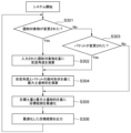
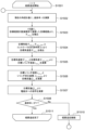
- 4 is a flowchart of a repose angle calculation unit, a maximum soil volume constraint calculation unit, and a target path planning calculation unit of a controller according to the first embodiment of the present invention.
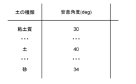
- 13 is an example of a table storing repose angles of a repose angle calculation unit.
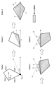
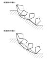
- 1 is an example of the geometry of a working device. An example of the relationship between the geometry of the work implement and the maximum soil volume constraint due to the angle of repose.
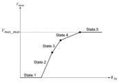
- 13 is a graph showing an example of the relationship between the absolute angle of a work implement and a maximum soil volume constraint. 13 is an example of a data format for a target route. 5 is a flowchart of a target path planning calculation unit of a controller according to the first embodiment of the present invention. 13 is an example of a target route after optimization calculation. 1 is a system diagram of a hydraulic system (hydraulic circuit) according to a first embodiment of the present invention.
- FIG. FIG. 2 is an example of an internal block diagram of a target path tracking unit of a controller according to the first embodiment of the present invention (when configured with only feedforward).
- FIG. 1 is an example of a flowchart of a target path tracking unit of a controller according to the first embodiment of the present invention (when configured with only feedforward).
- 13 is a specific example of a target angle extracted by the plan extraction unit. 13 shows a specific example of coefficients for an actuator speed calculation unit.
- FIG. 2 is an example of an internal block diagram of a target path tracking unit of a controller according to the first embodiment of the present invention (when feedback is used).
- 13 is an example of a flowchart of a target path tracking unit of a controller according to the first embodiment of the present invention (when feedback is used).
- 13 is a specific example of a target angle extracted by the plan extraction unit.
- FIG. 11 is a system diagram of a control system according to a second embodiment of the present invention. 13 is a graph showing an example of the relationship between the absolute angle of a work implement and a maximum soil volume constraint in the second embodiment of the present invention. 11A and 11B are diagrams comparing the operations and effects of the first and
- the embodiment of the present invention is described with respect to a backhoe-type shovel, it can be applied to all work machines that can move earth and sand with a work implement including a bucket. Specifically, this includes all shovels, such as loading-type shovels, two-piece shovels, and offset shovels, as well as wheel loaders and skid steer loaders.
- shovels such as loading-type shovels, two-piece shovels, and offset shovels, as well as wheel loaders and skid steer loaders.
- FIG. 1 is a perspective view of a hydraulic excavator 1 equipped with a control system including a control device (controller) of the present invention.
- the hydraulic excavator (hereinafter simply referred to as excavator) 1 comprises a lower running body 1C, an upper rotating body 1B rotatably attached to the lower running body 1C via a rotating device 4, and an articulated front 1A attached to the upper rotating body 1B.
- the front 1A is made up of a boom 8 rotatably attached to the upper rotating body 1B, an arm 9 rotatably attached to the boom 8, a bucket 10 rotatably attached to the arm 9, a bucket link 13 rotatably attached to the bucket 10 and the arm 9, a boom cylinder 5 connected to the boom 8 and upper rotating body 1B and changing the rotation angle of the boom 8 and upper rotating body 1B, an arm cylinder 6 connected to the boom 8 and arm 9 and changing the rotation angle of the boom 8 and arm 9, and a bucket cylinder 7 connected to the arm 9 and bucket link 13 and changing the rotation angle of the bucket 10 via the bucket link 13.
- the lower running structure 1C is equipped with a track mechanism driven by a travel motor 3, allowing the vehicle body to move.
- the slewing device 4 is composed of a slewing motor 11 that changes the rotation angle of the lower running structure 1C and the upper rotating structure 1B.
- a controller 20 equipped with the control system of the present invention and an input device 25 are provided on the upper rotating structure 1B.
- the control system of the present invention may be configured via wireless communication or the like as long as the excavation path can be calculated, and all components do not need to be mounted on the vehicle body.
- the work machine instead of the controller 20 and input device 25, the work machine (shovel 1) may be provided with a communication terminal, and the control system, its calculation device, and input device may be external.
- the shovel 1 has a boom angle measuring device 21a provided on the boom 8, which measures the relative rotation angle between the upper rotating body 1B and the boom 8, an arm angle measuring device 21b provided on the arm 9, which measures the relative rotation angle between the boom 8 and the arm 9, and a bucket angle measuring device 21c provided on the bucket 10, which measures the rotation angle between the arm 9 and the bucket 10.
- angle and angular velocity measuring device is assumed to be an angle sensor and is described as an angle measuring device, but as long as it can measure and calculate the relative angle, the form is not important, and the relative angle may be calculated based on the ground angle measured by an IMU (Inertial Measurement Unit) or the like.
- IMU Inertial Measurement Unit
- the shovel 1 also has a topography measuring device 22 mounted on the upper rotating body 1B, which can measure the topography of the area excavated by the bucket 10.
- multiple terrain measuring devices 22 may be provided, taking into consideration blind spots caused by the front 1A.
- the terrain measurement device 22 can be anything that can measure the surface shape of the terrain, such as a Lidar or stereo camera.
- FIG. 2 is a system diagram of a control system mounted on the controller 20 of this embodiment.
- the control system includes, as input devices 25, a target soil volume input unit 201 for inputting the target soil volume, a geometric shape input unit 203 for inputting the geometric shape (geometric information) of the bucket 10 as the work equipment, and an excavation target input unit 204 for inputting the type of excavation target, and data is input from these input devices 25.
- the work equipment geometric shape input unit 203 and the excavation target input unit 204 may be configured to directly input specific numerical values or to select from a list created in advance. Examples of the geometric shapes of the work equipment will be described later.
- the control system includes a controller 20, a repose angle calculation unit 205 that calculates the repose angle based on information about the excavation target, a maximum soil volume constraint calculation unit 206 that calculates the constraint on the maximum soil volume that can be loaded into the bucket 10 based on the repose angle and the geometric shape of the bucket 10, a mechanism information recording unit 208 that records mechanism information such as the length of the boom 8 and arm 9, a target path planning calculation unit 207 that plans a target path for the boom 8, arm 9, and bucket 10 of the work device based on the target soil volume, the terrain shape measured by the terrain measuring device 22, the maximum soil volume constraint, the geometric shape of the work device, and the mechanism information, and a target path following unit 209 that calculates solenoid valve commands to solenoid valves 62, 63, and 64 ( Figure 11) to control the boom 8, arm 9, and bucket 10 so as to follow the target path planned by the target path planning calculation unit 207.
- FIG. 3 is a flow chart of the repose angle calculation unit 205, the maximum soil volume constraint calculation unit 206, and the target path planning calculation unit 207 of the controller 20 of this embodiment.
- the repose angle is calculated based on the input information on the excavation object (S302) (repose angle calculation unit 205).
- the bucket 10 has been changed (S303). If the bucket 10 has been changed and after the process of S302 (calculating the repose angle), the maximum soil volume constraint is calculated based on the geometric shape and repose angle of the changed bucket 10 (S304) (maximum soil volume constraint calculation unit 206).
- the target route is calculated based on the target soil volume and maximum soil volume constraint (S305), and the calculated target route is output (S306) (target route plan calculation unit 207).
- calculation method in this embodiment is just one example, and any method that can calculate the maximum soil volume constraint based on the geometric shape will do.
- Figure 5 shows the geometric information of the bucket 10.
- the geometric information of the bucket 10 is composed of multiple points on the bucket 10, multiple lines connecting the points, and a surface enclosed by the multiple lines, and is approximated by a rectangular prism that contains the shape of the bucket 10.
- the vertices of the rectangular prism that is the geometric shape of the bucket 10 are called Pos. 1 to 4, 5 to 8 counterclockwise from the corner near the toe position, and the sides are called Sides. 1 to 4, 5 to 8.
- the geometric information is approximated by a rectangular prism, but in consideration of the calculation speed, any curved shape such as a polygonal prism or mesh data may be used, and the calculation method described below may be modified as appropriate.
- FIG. 6 is a schematic diagram showing an example of the relationship between the geometric shape of the bucket 10 and the maximum soil volume constraint due to the repose angle ⁇
- FIG. 7 is a graph showing an example of the relationship between the absolute angle ⁇ bk of the bucket 10 and the maximum soil volume constraint V max .
- the maximum soil volume constraint V max is determined based on the geometric shape and repose angle ⁇ of the bucket 10 and corresponds to the absolute angle (angle with respect to the ground) ⁇ bk of the bucket 10 .
- the path plan or target path refers to a data format in which the progress rate t (0 to 1) of the excavation operation and the relative angles of the boom 8, arm 9, and bucket 10 are arranged in chronological order (see Figure 8).
- FIG. 9 shows a flowchart of the target path optimization method in S305, that is, a flowchart of the target path planning calculation unit 207 of the controller 20 in this embodiment.
- the optimization method in S305 may be any method that optimizes the path relative to the relative angles of the boom 8, arm 9, and bucket 10.
- the optimization parameters may be determined as shown in Equations 2 to 4 (S701, S702). [Equation 2]
- a loop calculation is performed at a progress rate t for the relative angles ⁇ bm_t , ⁇ am_t , and ⁇ bk_t of the boom 8, arm 9, and bucket 10 defined by equations 2 to 4 (S703).
- the number of loops is appropriately determined based on the calculation speed and accuracy of the computer within the range of the progress rate t.
- Equation 5 the position P i ' of the geometric information of bucket 10 at the current progress rate t is calculated based on the geometric information of bucket 10 (coordinates P 1 to 8 of Pos. 1 to 8 in Figure 5) and the relative angles ⁇ bm_t , ⁇ am_t , and ⁇ bk_t (S705).
- T in Equation 5 is a coordinate transformation matrix (a forward kinematics transformation, for example, a homogeneous transformation matrix) determined from the geometric arrangement and joint directions of the boom 8, the arm 9, and the bucket 10.
- the volume of the overlap (Boolean product calculation) of the solid formed by P i ' and the terrain shape of the previous progress rate is set as the excavated volume V dig_t at the progress rate t (S706).
- the shape excluding the solid formed by P i ' (overlapping portion of the geometric information of the bucket 10) from the terrain shape of the previous progress rate is set as the terrain shape at the progress rate t (S707).
- an evaluation is performed based on the volume after excavation completion and the maximum soil volume constraint (S711).
- the evaluation value J is calculated using predetermined arbitrary weights ⁇ 1 and ⁇ 2 , the evaluation value J1 related to the volume after excavation completion, and the evaluation value J2 based on the maximum soil volume constraint (Equation 6). [Equation 4]
- the evaluation value J1 based on the volume after excavation is completed is calculated using the target excavation volume Vdigtarget and the excavated volume Vdig_t , which are preset in the target soil volume input unit 201 (Equation 7). [Equation 5]
- FIG. 11 is a system diagram of the hydraulic system (hydraulic circuit) which is the means for achieving the target flow rate in this embodiment (the downstream actuator control means in FIG. 2).
- the hydraulic system 50 comprises a tank 52 for storing hydraulic oil, a pump 51 that is driven by a prime mover such as an engine (not shown) to pressurize the hydraulic oil in the tank 52 and supply pressurized oil to the hydraulic system 50, a regulator 57 that controls the discharge flow rate of the pump 51, a relief valve 53 that is connected between the pump 51 and the tank 52 and limits the maximum value of the supply pressure, a spool valve 54 that controls the supply and discharge of pressurized oil to the boom cylinder 5 in response to the pilot pressure received at pressure receiving parts A1 and A2, and a pressure regulator 55 that controls the supply and discharge of pressurized oil to the arm cylinder 6 in response to the pilot pressure received at pressure receiving parts B1 and B2.
- a prime mover such as an engine (not shown) to pressurize the hydraulic oil in the tank 52 and supply pressurized oil to the hydraulic system 50
- a regulator 57 that controls the discharge flow rate of the pump 51
- a relief valve 53 that is connected between the pump 51 and the tank 52 and limits
- the bucket cylinder 7 includes a spool valve 55 that controls the supply and discharge of pressure oil to and from the bucket cylinder 7, a spool valve 56 that controls the supply and discharge of pressure oil to and from the bucket cylinder 7 in response to the pilot pressure received by the pressure receiving parts C1 and C2, a pilot pump 61 that is driven by a prime mover such as an engine (not shown) and supplies pilot pressure oil, and solenoid valves 62, 63, and 64 (also see FIG. 2) that reduce the pressure of the pilot pressure oil in response to a command (solenoid valve command) from the controller 20 and generate pilot pressure acting on the pressure receiving parts (A1, A2), (B1, B2), and (C1, C2) of the spool valves 54, 55, and 56.
- a command solenoid valve command
- the spool valves 54, 55, and 56 can control the flow rate and direction of the pressurized oil supplied to the boom cylinder 5, arm cylinder 6, and bucket cylinder 7 actuators according to the pilot pressure controlled by the controller 20, thereby controlling the operation of the boom 8, arm 9, and bucket 10.
- the actuator's operating speed and direction are controlled by controlling the pilot pressure, but the spool valves 54, 55, 56 themselves may be solenoid valves controlled by the controller 20, or the actuators (all or part of them) may be electrically powered. Any form is acceptable as long as the actuator's operating speed and direction can be controlled by the controller 20.
- Fig. 12 is an example of an internal block diagram of the target path tracking unit 209 in Fig. 2.
- the target path tracking unit 209 is composed of a plan extraction unit 1001, an angular velocity calculation unit 1002, an actuator velocity calculation unit 1003, a flow rate calculation unit 1004, and a solenoid valve operation unit 1005.
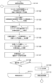
- Fig. 13 is a flowchart of the internal block diagram in Fig. 12.
- the target path tracking unit 209 sets the progress rate t to 0 and starts path tracking (S1101).
- the target path tracking unit 209 calculates the update amount ⁇ t of the progress rate based on the controller's calculation period (calculation time) ⁇ n and a predetermined k (S1102) (plan extraction unit 1001), and sequentially updates the progress rate t of the path plan for each controller period (S1108, S1109, S1110).
- k used in the calculation in S1102 can be any value as long as the actuator speed does not exceed a predetermined maximum value in the actuator speed calculation unit 1003 at the subsequent stage.
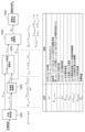
- the target path tracking unit 209 extracts a target angle ⁇ act_t for the current progress rate t and a next target angle ⁇ act_t+ ⁇ t based on the target path planned by the target path plan calculation unit 207 (S1103) (plan extraction unit 1001) (specific example: see FIG. 14).
- the target path tracking unit 209 calculates the target cylinder flow rate based on these target angles, mechanism design values, cylinder design values, etc. (S1104, S1105, S1106) (angular velocity calculation unit 1002, actuator velocity calculation unit 1003, flow rate calculation unit 1004) (also see FIG. 15), and calculates commands (solenoid valve commands) to the solenoid valves 62, 63, 64 based on the target cylinder flow rate (S1107) (solenoid valve operation unit 1005).
- Fig. 16 is another example of the internal block diagram of the target path tracking unit 209 in Fig. 2.
- the target path tracking unit 209 is composed of a plan extraction unit 1401, an angular velocity calculation unit 1402, an actuator velocity calculation unit 1403, a flow rate calculation unit 1404, and a solenoid valve operation unit 1405.
- Fig. 17 is a flowchart of the internal block diagram in Fig. 16.
- an angle measurement device 21 consisting of a boom angle measurement device 21a, an arm angle measurement device 21b, and a bucket angle measurement device 21c is required.
- the target route tracking unit 209 sets the progress rate t to 0 and starts route tracking (S1501).
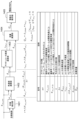
- the target path tracking unit 209 calculates a target angle ⁇ act_t in the plan extraction unit 1401 based on the current angle ⁇ act_sens obtained from the angle measurement device 21 (S1502, S1503).
- Any method for calculating the target angle may be used as long as it is uniquely determined based on the current angle. For example, one method is to set the progress rate corresponding to the angle closest to the current angle in the route plan as the current progress rate t, and use a plan that is a predetermined number ⁇ t2 ahead of that t (see FIG. 18).
- the angular velocity calculation unit 1402, actuator velocity calculation unit 1403, flow rate calculation unit 1404, and solenoid valve operation unit 1405 in FIG. 16, and S1504 to S1511 in FIG. 17 are similar to the angular velocity calculation unit 1002, actuator velocity calculation unit 1003, flow rate calculation unit 1004, and solenoid valve operation unit 1005 in FIG. 12, and S1104 to S1111 in FIG. 13, so their explanation will be omitted.
- Feedback allows deviations from the plan to be corrected during execution, allowing the system to follow the plan more accurately than if it were configured with feedforward alone.
- Example 2 An operation in which all the soil and sand spills out of the bucket is an operation in which the soil and sand simply moves. For example, an excavation operation in which the opening of the bucket is facing almost directly downward. In this case, the bucket passing volume ⁇ soil volume in the bucket, which is assumed in the excavation path plan in Example 1, no longer holds true.
- Example 1 the amount of soil in the bucket is always kept below the maximum soil volume constraint during excavation, but during actual excavation, due to the influence of the soil and the speed and inertia of the bucket itself, soil will not spill out of the bucket even if it exceeds the maximum soil volume constraint to some extent. Naturally, the soil will spill out when the bucket is stopped.
- Example 1 this point is not taken into consideration, so the freedom in route selection is limited.
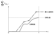
- Example 2 "a certain amount of play” is added to the maximum soil volume constraint curve, thereby expanding the freedom in route selection.
- FIG. 19 is a system diagram of a control system mounted on the controller 20 of this embodiment.
- control system includes a soil volume margin input unit 801 that can input soil volume margin using the input device 25 or the like, and a maximum soil volume constraint calculation unit with margin 802 that replaces the maximum soil volume constraint calculation unit 206 and calculates the maximum soil volume constraint based on the soil volume margin, the repose angle, and the geometric shape of the work device.
- a target path plan calculation unit 207 plans a target path based on the maximum earth volume constraint V′ max with margins calculated by a maximum earth volume constraint calculation unit 802 with margins.
- the soil volume margin added to Vmax may be constant with respect to the absolute angle ⁇ bk of the bucket 10, or may be variable according to the absolute angle ⁇ bk of the bucket 10. For example, the soil volume margin may be increased as the absolute angle ⁇ bk of the bucket 10 is smaller.
- the trade-off relationship between the amount of spillage and the degree of freedom of path selection can be adjusted by the angle margin, so that a system capable of adjusting the accuracy and the degree of freedom of path can be provided.
- the difference between the first embodiment and the second embodiment is shown in FIG. 21.
- the maximum soil volume constraint V max does not become greater than 0 until the line segment extended in the ⁇ direction from Pos.1 coincides with Side.1 as shown in Equation 1, and excavation is not performed. In other words, in a specific starting posture and terrain, excavation is not performed until halfway, and an operation of tracing the ground surface with the tip of the bucket is performed.
- the working machine (hydraulic excavator 1) of this embodiment includes a working implement including the bucket 10, and a control device (controller 20) that controls the excavation operation of the working implement, and the control device (controller 20) includes a target path planning calculation unit 207 that plans a target excavation path that represents a target attitude of the working implement including the ground angle of the bucket 10 in a time series (for continuing the excavation operation of the working implement) based on a preset target excavation volume (target soil volume), topographical information of the excavation range by the working implement (bucket 10), and a maximum excavation volume constraint (maximum soil volume constraint) for the ground angle of the bucket 10, and a target path following unit 209 that controls the operation of the working implement including the ground angle of the bucket 10 so as to follow the target excavation path (so as to operate along the target path).
- the target path planning calculation unit 207 inputs topographical information of the excavation range by the working implement (bucket 10) measured by a topography measuring device 22 (during
- the target path planning calculation unit 207 determines the maximum excavation volume constraint (maximum soil volume constraint) based on the geometric shape of the bucket 10.
- the excavation path can be planned even if the shape of the bucket 10 changes.
- the target path planning calculation unit 207 determines the maximum excavation volume constraint (maximum soil volume constraint) based on information about the excavation object (the type and properties of the object that affect the repose angle).
- the excavation path can be planned even if the object to be excavated changes.
- the target path planning calculation unit 207 inputs information about the excavation target from the input device 25 (excavation target input unit 204).
- any object to be excavated can be specified.
- the target path planning calculation unit 207 plans the target excavation path based on a maximum excavation volume constraint with margin (maximum soil volume constraint) that adds an excavation volume margin (soil volume margin) to the maximum excavation volume constraint (maximum soil volume constraint).
- the target path planning calculation unit 207 sets the excavation volume margin (soil volume margin) according to the ground angle of the bucket 10.
- the accuracy and freedom of the route can be adjusted.
- the present invention is not limited to the above-described embodiments, and includes various modified forms.
- the above-described embodiments have been described in detail to clearly explain the present invention, and are not necessarily limited to those having all of the configurations described. It is also possible to replace part of the configuration of one embodiment with the configuration of another embodiment, and it is also possible to add the configuration of another embodiment to the configuration of one embodiment. It is also possible to add, delete, or replace part of the configuration of each embodiment with other configurations.
- each function of the controller in the above-described embodiment may be realized in hardware, part or all, by designing it as an integrated circuit, for example.
- each function may be realized in software, by a processor interpreting and executing a program that realizes each function.
- Information such as the programs, tables, and files that realize each function may be stored in a storage device within the controller, a hard disk, an SSD (Solid State Drive), or other recording device, or an IC card, SD card, DVD, or other recording medium.
Landscapes
- Engineering & Computer Science (AREA)
- Mechanical Engineering (AREA)
- Mining & Mineral Resources (AREA)
- Civil Engineering (AREA)
- General Engineering & Computer Science (AREA)
- Structural Engineering (AREA)
- Operation Control Of Excavators (AREA)
Priority Applications (3)
| Application Number | Priority Date | Filing Date | Title |
|---|---|---|---|
| JP2025548497A JPWO2025069595A1 (https=) | 2023-09-26 | 2024-06-17 | |
| KR1020267003489A KR20260032609A (ko) | 2023-09-26 | 2024-06-17 | 작업 기계 |
| CN202480051738.2A CN121646667A (zh) | 2023-09-26 | 2024-06-17 | 作业机械 |
Applications Claiming Priority (2)
| Application Number | Priority Date | Filing Date | Title |
|---|---|---|---|
| JP2023-163335 | 2023-09-26 | ||
| JP2023163335 | 2023-09-26 |
Publications (1)
| Publication Number | Publication Date |
|---|---|
| WO2025069595A1 true WO2025069595A1 (ja) | 2025-04-03 |
Family
ID=95202751
Family Applications (1)
| Application Number | Title | Priority Date | Filing Date |
|---|---|---|---|
| PCT/JP2024/021802 Pending WO2025069595A1 (ja) | 2023-09-26 | 2024-06-17 | 作業機械 |
Country Status (4)
| Country | Link |
|---|---|
| JP (1) | JPWO2025069595A1 (https=) |
| KR (1) | KR20260032609A (https=) |
| CN (1) | CN121646667A (https=) |
| WO (1) | WO2025069595A1 (https=) |
Citations (9)
| Publication number | Priority date | Publication date | Assignee | Title |
|---|---|---|---|---|
| WO2010148449A1 (en) * | 2009-06-25 | 2010-12-29 | Commonwealth Scientific And Industrial Research Organisation | Autonomous loading |
| WO2017002749A1 (ja) * | 2015-06-29 | 2017-01-05 | 日立建機株式会社 | 作業機械の作業支援システム |
| CN106836364A (zh) * | 2017-01-17 | 2017-06-13 | 大连理工大学 | 智能挖掘机的自动控制系统及最优轨迹规划方法 |
| WO2019189260A1 (ja) * | 2018-03-27 | 2019-10-03 | 住友重機械工業株式会社 | ショベル |
| JP2020128695A (ja) * | 2015-09-16 | 2020-08-27 | 住友重機械工業株式会社 | ショベル及びショベル用のシステム |
| WO2021009873A1 (ja) * | 2019-07-17 | 2021-01-21 | 日本電気株式会社 | 掘削軌道生成方法、システム、及び掘削軌道生成装置 |
| CN113684876A (zh) * | 2021-09-01 | 2021-11-23 | 广西科技大学 | 一种基于作业性能数据插值的装载机铲装轨迹优化方法 |
| CN113833038A (zh) * | 2021-09-01 | 2021-12-24 | 广西科技大学 | 一种面向自动铲装的装载机铲装轨迹规划方法 |
| JP7088792B2 (ja) | 2018-09-12 | 2022-06-21 | 株式会社小松製作所 | 作業機械、制御装置、および制御方法 |
-
2024
- 2024-06-17 JP JP2025548497A patent/JPWO2025069595A1/ja active Pending
- 2024-06-17 WO PCT/JP2024/021802 patent/WO2025069595A1/ja active Pending
- 2024-06-17 CN CN202480051738.2A patent/CN121646667A/zh active Pending
- 2024-06-17 KR KR1020267003489A patent/KR20260032609A/ko active Pending
Patent Citations (9)
| Publication number | Priority date | Publication date | Assignee | Title |
|---|---|---|---|---|
| WO2010148449A1 (en) * | 2009-06-25 | 2010-12-29 | Commonwealth Scientific And Industrial Research Organisation | Autonomous loading |
| WO2017002749A1 (ja) * | 2015-06-29 | 2017-01-05 | 日立建機株式会社 | 作業機械の作業支援システム |
| JP2020128695A (ja) * | 2015-09-16 | 2020-08-27 | 住友重機械工業株式会社 | ショベル及びショベル用のシステム |
| CN106836364A (zh) * | 2017-01-17 | 2017-06-13 | 大连理工大学 | 智能挖掘机的自动控制系统及最优轨迹规划方法 |
| WO2019189260A1 (ja) * | 2018-03-27 | 2019-10-03 | 住友重機械工業株式会社 | ショベル |
| JP7088792B2 (ja) | 2018-09-12 | 2022-06-21 | 株式会社小松製作所 | 作業機械、制御装置、および制御方法 |
| WO2021009873A1 (ja) * | 2019-07-17 | 2021-01-21 | 日本電気株式会社 | 掘削軌道生成方法、システム、及び掘削軌道生成装置 |
| CN113684876A (zh) * | 2021-09-01 | 2021-11-23 | 广西科技大学 | 一种基于作业性能数据插值的装载机铲装轨迹优化方法 |
| CN113833038A (zh) * | 2021-09-01 | 2021-12-24 | 广西科技大学 | 一种面向自动铲装的装载机铲装轨迹规划方法 |
Also Published As
| Publication number | Publication date |
|---|---|
| CN121646667A (zh) | 2026-03-10 |
| JPWO2025069595A1 (https=) | 2025-04-03 |
| KR20260032609A (ko) | 2026-03-09 |
Similar Documents
| Publication | Publication Date | Title |
|---|---|---|
| CN113107043B (zh) | 使用传感器融合控制机器的运动 | |
| US10401176B2 (en) | System and method for determining machine state using sensor fusion | |
| US10521703B2 (en) | System and method for controlling machine pose using sensor fusion | |
| CN109757113B (zh) | 作业机械 | |
| US10459462B2 (en) | Sensor fusion feedback for controlling fluid pressures in a machine | |
| CN112639212B (zh) | 作业机械 | |
| CN111936706B (zh) | 平整模式集成 | |
| US20140064897A1 (en) | Single stick operation of a work tool | |
| JP6450008B2 (ja) | 作業機制御装置および作業機械 | |
| US11585071B2 (en) | Hystat swing motion actuation, monitoring, and control system | |
| US20250059725A1 (en) | Work machine | |
| WO2019123927A1 (ja) | 作業機械 | |
| CN116096972B (zh) | 作业机械 | |
| US11377813B2 (en) | Work machine with semi-automatic excavation and shaping | |
| CN116897235A (zh) | 用于对土方机械的循环操作进行自动控制的方法 | |
| JP7689057B2 (ja) | 建設機械 | |
| CN115715344B (zh) | 作业机械以及作业机械的控制系统 | |
| KR102587721B1 (ko) | 작업 기계 | |
| WO2025069595A1 (ja) | 作業機械 | |
| JP2025053883A (ja) | 作業機械の制御装置 | |
| WO2024195267A1 (ja) | 作業機械の制御システム | |
| WO2025154761A1 (ja) | 作業機械 |
Legal Events
| Date | Code | Title | Description |
|---|---|---|---|
| 121 | Ep: the epo has been informed by wipo that ep was designated in this application |
Ref document number: 24871400 Country of ref document: EP Kind code of ref document: A1 |
|
| ENP | Entry into the national phase |
Ref document number: 2025548497 Country of ref document: JP Kind code of ref document: A |
|
| WWE | Wipo information: entry into national phase |
Ref document number: 2025548497 Country of ref document: JP |
|
| ENP | Entry into the national phase |
Ref document number: 1020267003489 Country of ref document: KR Free format text: ST27 STATUS EVENT CODE: A-0-1-A10-A15-NAP-PA0105 (AS PROVIDED BY THE NATIONAL OFFICE) |
|
| WWE | Wipo information: entry into national phase |
Ref document number: 1020267003489 Country of ref document: KR |
|
| WWP | Wipo information: published in national office |
Ref document number: 1020267003489 Country of ref document: KR |