WO2025069410A1 - 風況情報提供システム、及び風況情報提供方法 - Google Patents
風況情報提供システム、及び風況情報提供方法 Download PDFInfo
- Publication number
- WO2025069410A1 WO2025069410A1 PCT/JP2023/035734 JP2023035734W WO2025069410A1 WO 2025069410 A1 WO2025069410 A1 WO 2025069410A1 JP 2023035734 W JP2023035734 W JP 2023035734W WO 2025069410 A1 WO2025069410 A1 WO 2025069410A1
- Authority
- WO
- WIPO (PCT)
- Prior art keywords
- wind
- condition information
- wind condition
- span
- saturation
- Prior art date
- Legal status (The legal status is an assumption and is not a legal conclusion. Google has not performed a legal analysis and makes no representation as to the accuracy of the status listed.)
- Pending
Links
Images









Classifications
-
- G—PHYSICS
- G01—MEASURING; TESTING
- G01H—MEASUREMENT OF MECHANICAL VIBRATIONS OR ULTRASONIC, SONIC OR INFRASONIC WAVES
- G01H9/00—Measuring mechanical vibrations or ultrasonic, sonic or infrasonic waves by using radiation-sensitive means, e.g. optical means
-
- G—PHYSICS
- G01—MEASURING; TESTING
- G01P—MEASURING LINEAR OR ANGULAR SPEED, ACCELERATION, DECELERATION, OR SHOCK; INDICATING PRESENCE, ABSENCE, OR DIRECTION, OF MOVEMENT
- G01P13/00—Indicating or recording presence, absence, or direction, of movement
-
- G—PHYSICS
- G01—MEASURING; TESTING
- G01P—MEASURING LINEAR OR ANGULAR SPEED, ACCELERATION, DECELERATION, OR SHOCK; INDICATING PRESENCE, ABSENCE, OR DIRECTION, OF MOVEMENT
- G01P5/00—Measuring speed of fluids, e.g. of air stream; Measuring speed of bodies relative to fluids, e.g. of ship, of aircraft
- G01P5/02—Measuring speed of fluids, e.g. of air stream; Measuring speed of bodies relative to fluids, e.g. of ship, of aircraft by measuring forces exerted by the fluid on solid bodies, e.g. anemometer
-
- G—PHYSICS
- G01—MEASURING; TESTING
- G01W—METEOROLOGY
- G01W1/00—Meteorology
Definitions
- the present invention relates to a wind condition information providing system and a wind condition information providing method.
- Patent Document 1 describes the detection of the speed and direction of wind blowing against a power line using a technology (distributed multipoint vibration measurement method, hereafter referred to as "DAS" (Distributed Acoustic Sensing)) that calculates vibrations caused by the expansion and contraction of the optical fiber based on the time from when pulsed light is incident on the optical fiber of an OPGW (Optical fiber composite overhead Ground Wire) until the backward Rayleigh scattered light returns, and the phase difference and intensity of the backward Rayleigh scattered light.
- DAS distributed multipoint vibration measurement method
- wind condition information information on wind conditions at the site where the power transmission line is located (hereinafter referred to as "wind condition information") is obtained remotely using a DAS.
- the present invention was made in consideration of this background, and aims to provide a wind condition information providing system and a wind condition information providing method that can stably provide meaningful wind condition information using DAS.
- a wind condition information providing system which is composed of an optical analysis unit and an information processing device, and obtains wind condition information, which is information indicating the current wind conditions in the span of the power line, based on the vibration intensity of the optical fiber obtained by DAS (Distributed Acoustic Sensing) at measurement points set along the optical fiber installed along the power line, and detects the presence or absence of a saturation state, which is a state in which the magnitude of the vibration intensity is above a predetermined threshold range and continues for a period of time that is greater than a predetermined threshold time.
- DAS Distributed Acoustic Sensing
- the wind condition information providing system also acquires the wind condition information based on a wind condition estimation component, which is a component in a specified frequency band, of the vibration intensity, and detects the presence or absence of the saturation state based on a saturation determination component, which is a component in a higher frequency band than the specified frequency band, of the vibration intensity.
- the wind condition information system detects the saturation state, it obtains the actual values of the change in wind speed over time at other observation points that are not in the saturated state during the saturation period in which the saturation state occurs, estimates the wind speed during the saturation period of the span based on the correlation between the actual measured value of the change in wind speed over time in the span and the actual value of the change in wind speed over time at the observation points, and complements the wind condition information during the saturation period of the span with the estimated wind speed.
- meaningful wind information can be provided stably using DAS.
- FIG. 1 is a diagram showing a schematic configuration of a wind condition information providing system.
- FIG. 2 is a diagram illustrating a mechanism for measuring a vibration state by a DAS.
- 1 is an example of a measured wind speed (parallel to the extension direction of the optical fiber).
- 1 is an example of a measured value of wind speed (in a direction perpendicular to the extending direction of the optical fiber).
- 1 is an example of a change in vibration intensity over time.
- 13 is an example of a change in vibration intensity over time for each frequency.
- 13 is an example of a change in vibration intensity over time when there is no saturation period.
- 13 is an example of a change in wind speed over time when there is no saturation period.
- 13 is an example of a change in vibration intensity over time when there is a saturation period.
- FIG. 11 is a schematic diagram illustrating a method for obtaining correlation in a first complementation method.
- FIG. 11 is a schematic diagram illustrating a first complementation method.
- FIG. 13 is a schematic diagram illustrating a method for obtaining correlation in a second complementation method.
- FIG. 11 is a schematic diagram illustrating a second complementation method.
- FIG. 2 is a diagram showing the main configuration of a wind condition information providing device. 2 is a block diagram showing main functions of the wind condition information providing device.
- FIG. FIG. 4 is a schematic diagram illustrating a main flow of a wind condition information provision process.
- 11 is a flowchart illustrating a wind condition information providing process.
- FIG 1 shows a schematic configuration of a wind condition information providing system (hereinafter referred to as "wind condition information providing system 1") described as one embodiment of the present invention.
- the wind condition information providing system 1 includes a wind condition information providing device 100 provided in a substation 6 or the like, and a wind condition information utilization device 300 that is communicatively connected to the wind condition information providing device 100. Both the wind condition information providing device 100 and the wind condition information utilization device 300 are configured using an information processing device (computer).
- the wind condition information providing device 100 uses the optical fiber 4a of the OPGW 4 (optical fiber composite overhead ground wire) (optical fiber composite overhead ground wire) installed on the power transmission line 3 as a vibration detection sensor, and obtains (estimates) the wind conditions (wind direction, wind speed) at each measurement point based on the vibration state at each measurement point using a technology (distributed multipoint vibration measurement method (hereinafter referred to as "DAS" (Distributed Acoustic Sensing))) that measures the vibration state (vibration intensity, vibration frequency) at each of multiple measurement positions (hereinafter referred to as "measurement points") set along the optical fiber 4a based on the expansion and contraction of the optical fiber 4a.
- DAS distributed multipoint vibration measurement method
- the DAS obtains the vibration state at each measurement point using, for example, the principle of a C-OTDR (Coherent detection Optical Time Domain Reflectometer).
- FIG 2 is a diagram explaining the mechanism by which the wind condition information providing device 100 measures the vibration state at each measurement point using DAS.
- the wind condition information providing device 100 inputs a light pulse (laser pulse, hereinafter also referred to as "incident light") from the end face of the optical fiber 4a, and measures the change speed ( ⁇ stretching frequency) of the phase difference of the backscattered light of the light pulse at each measurement point.
- the phase difference is estimated from the intensity change due to interference between the backscattered lights.
- the wind condition information providing device 100 determines the vibration frequency of the longitudinal wave and transverse wave of the optical fiber 4a at each measurement point (for example, vibration frequency in the range of up to 10 kHz).
- the wind condition information providing device 100 also determines the vibration intensity (spectral intensity, vibration amplitude) at each measurement point based on the phase difference for each vibration frequency.
- the wind condition information providing device 100 determines the position of each measurement point (the distance from the end face) based on the elapsed time from when the incident light is incident on the end face to when the returned light is received.
- the above measurement points are set, for example, at predetermined intervals d (m) along the optical fiber that are shorter than the span of the transmission tower 2 (0 (m), d (m), ..., N (m), N + d (m), N + 2 d (m)).
- predetermined interval d is 5 (m) and measurement points are set over a maximum range of 70 (km) of the transmission line 3, approximately 14,000 measurement points will be set along the optical fiber.
- the wind condition information providing device 100 obtains the vibration state of each span (between adjacent transmission towers 2) of the power line 3 based on the vibration state of each measurement point.
- Non-Patent Document 1 Search on the vibration characteristics of power lines during strong winds", Urban Disaster Management, Inayoshi Ken, Kyushu University, [online], Internet ⁇ URL: https://www.hues.kyushu-u.ac.jp/wp-content/uploads/2022/10/2HE02019E.pdf>
- the vibration state of the optical fiber 4a in the span has a certain correlation with the wind conditions in the span. Therefore, a model (statistical model, machine learning model, etc.) that represents the above correlation is generated in advance, and the wind conditions in the span can be obtained by inputting the vibration state obtained for the measurement points of the span into the model.
- the vibration mode (natural vibration mode) of the vibration state of the optical fiber 4a differs depending on the wind speed (the vibration state is nonlinear with respect to changes in wind speed)
- the above model is generated for each range of wind speeds (for example, a model is generated for cases where the wind speed is less than 3 (m/s) and a model is generated for cases where the wind speed is 3 (m/s) or more).
- the characteristics of the vibration state of the optical fiber 4a differ for each span due to differences in the span length and the installation state of the OPGW 4, the above model is generated for each span.
- the specified interval d (m) is shorter than the span of the transmission tower 2, multiple measurement points will be included in one span, but in that case, the method of acquiring the wind conditions for that span based on the vibration state of each measurement point is not necessarily limited.
- the wind conditions for the span may be the wind conditions for the measurement point with the highest wind speed among the multiple measurement points or the average value of the wind conditions for each measurement point.
- the wind condition information providing device 100 inputs the vibration state of the measurement points on the span into the above model, and determines the wind speed components (referred to as the "parallel direction component” and the “orthogonal direction component”, respectively) for the direction along the optical fiber 4a (the direction of the longitudinal waves; the extension direction of the optical fiber 4a; hereafter referred to as the "parallel direction”) and the direction perpendicular to the extension direction of the optical fiber 4a (the direction of the transverse waves; hereafter referred to as the "orthogonal direction”), and determines the wind conditions (wind direction, wind speed) on the span based on the determined parallel direction component and orthogonal direction component.
- the wind speed components referred to as the "parallel direction component” and the “orthogonal direction component”
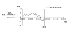
- Figure 3A shows an example of the time change (time series data) of the parallel component of wind speed in a span (hereinafter referred to as the "measured value (parallel direction)”), calculated using the above mechanism.
- Figure 3B shows an example of the time change of the perpendicular component of wind speed in the above span (hereinafter referred to as the “measured value (perpendicular direction)”), calculated by the wind condition information providing device 100.
- the horizontal axis of the graphs shown in each figure is time, and the vertical axis is wind speed (m/s).
- wind speed refers to at least either the parallel component of wind speed or the perpendicular component of wind speed.
- the wind condition information providing device 100 provides (transmits) information indicating the current wind conditions (hereinafter referred to as “wind condition information”) on each span (hereinafter referred to as “site") of the power transmission line 3, which is obtained by the above mechanism, to the wind condition information utilization device 300.
- the wind information utilization device 300 uses the wind information provided by the wind information providing device 100 to carry out or support business or work.
- the wind information utilization device 300 provides wind information to the operator of an unmanned aerial vehicle (drone) that flies along a power transmission line 3 to patrol and inspect power facilities (power transmission tower 2, power transmission line 3, substation equipment 4, etc.) to determine whether or not the drone can fly.
- the wind information utilization device 300 functions as an element of an operation control system that wirelessly communicates with the unmanned aerial vehicle, monitors the unmanned aerial vehicle, provides various information, and controls operation.
- the wind information utilization device 300 functions as an element of an information processing system that uses wind information to perform dynamic rating (a technology for operating power transmission and substation equipment by constantly monitoring the condition of the equipment and changing the current capacity according to the local conditions).
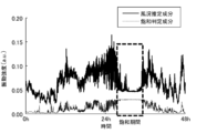
- Figure 4A shows the change over time in vibration strength of optical fiber 4a measured for a certain span of power transmission line 3.
- the horizontal axis of the graph in the figure is time (h), and the vertical axis is vibration strength (arbitrary units).
- the graph shown with a solid line is the average value of vibration strength in the frequency band used to estimate wind conditions (e.g., 0 to 25 Hz) among the frequency components of vibration strength (hereinafter referred to as the "wind condition estimation component”).
- the graph shown with a dotted line is the average value of vibration strength in the frequency band higher than the wind condition estimation component (e.g., 450 to 475 Hz) among the frequency components of vibration strength (hereinafter referred to as the "saturation determination component").
- Figure 4B shows the time variation (time series data) of vibration strength for each frequency in a specified frequency range (0-500 Hz) measured for the above span.
- the horizontal axis is frequency (Hz) and the vertical axis is time (h).
- time flows from the top to the bottom of the page.
- the shade of color represents vibration strength (the lighter the color, the greater the vibration strength).
- the vibration intensity of both the wind condition estimation component and the saturation determination component remains constant and barely changes.
- the vibration intensity of the saturation determination component remains almost constant during the above period (hereinafter, this state will be referred to as the "saturation state").
- the vibration intensity is represented by the time series difference (- ⁇ to + ⁇ ) (hereinafter referred to as the "phase difference") of the phase shift of the vibration caused by the expansion and contraction of the optical fiber 4a.
- the phase difference For example, if the vibration is small and the phase difference is 2 ⁇ or less, the vibration intensity can be observed as a continuous change. However, if the phase difference exceeds 2 ⁇ due to the influence of a strong wind, the change in vibration intensity becomes extremely small as in the above period, and the optical fiber 4a reaches a saturated state.
- the amount of wind required to saturate the optical fiber 4a depends on the type of optical fiber 4a. For example, a thin optical fiber 4a is lighter and therefore reaches a saturated state at a lower wind speed than a thick optical fiber 4a.
- FIG. 5A shows an example of the time change in vibration intensity of the wind condition estimation component and saturation determination component (time change in vibration intensity obtained by DAS) when there is no period in which the optical fiber 4a is saturated (hereinafter referred to as the "saturation period").
- FIG. 5B also shows an example of an estimate of the time change in wind speed obtained based on the wind condition estimation component of FIG. 5A.
- FIG. 5B also shows the time change in wind speed observed by a reference anemometer (Doppler lidar). As shown in the figure, the estimate of the time change in wind speed based on the wind condition estimation component and the observation value of the reference anemometer match well over the entire period shown in the figure.
- Doppler lidar Doppler lidar
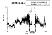
- Figure 6A is an example of the time change in vibration intensity of the wind condition estimation component and saturation judgment component (time change in vibration intensity obtained by DAS) when there is a saturation period.
- Figure 6B is an example of an estimated value of the time change in wind speed obtained based on the wind condition estimation component of Figure 6A.
- Figure 6B also shows the time change in wind speed observed by a reference anemometer (Doppler lidar). As shown in the figure, during periods other than the saturation period, the estimated value of the time change in wind speed based on the wind condition estimation component and the observed value of the reference anemometer match, but during the saturation period, the two differ greatly.
- the wind condition information providing device 100 monitors in real time whether or not the optical fiber 4a is saturated, and when it detects that the optical fiber 4a is saturated, it complements the wind conditions (wind condition information) during the saturated period using the following method.
- the wind condition information providing device 100 determines the time change in wind speed during the saturation period of a span in which a saturation state exists (hereinafter referred to as the "first span") based on the correlation between the actual value of the time change in wind speed of the first span and the actual value of the time change in wind speed of another span in the vicinity of the first span that is not saturated during the saturation period of the first span (hereinafter referred to as the "second span”) (hereinafter this method is referred to as the "first complementation method").
- the second span may not be saturated (see, for example, Non-Patent Document 2 ("On the influence of terrain and obstacles on wind", Omuro Kogen, [searched September 8, 2023], [online], Internet ⁇ URL: http://www.chl-izu.jp/weather/expfiles/expwind.htm>)).
- the second span can correctly obtain the change in wind speed over time during the saturation period of the first span. Therefore, in the first complementation method, the change in wind speed over time in the second span is used to estimate the wind speed during the saturation period of the first span.
- FIG. 7A and 7B are schematic diagrams illustrating the first complementation method.
- the wind condition information providing device 100 obtains a correlation (here, the average value of the ratio between the actual value of the time change of the wind speed in the first span and the actual value of the time change of the wind speed in the second span) between the actual value.
- the wind condition information providing device 100 obtains the wind speed in the saturation period of the first span by multiplying the wind speed in the saturation period of the second span by the average value of the ratio.
- the method of obtaining the correlation is not necessarily limited, and the correlation may be obtained by other methods such as statistical methods or machine learning.
- the wind condition information providing device 100 determines the time change in wind speed during the saturation period of a span that is in a saturated state based on the correlation between the actual value of the time change in wind speed in that span and the observed value of the time change in wind speed at a specified observation point of wind conditions located near that span (hereinafter, this method is referred to as the "second complementation method").
- the observed values of the time change in wind speed at the above observation points are provided to the wind condition information providing device 100 via a communication network from, for example, other wind condition observation systems (systems that collect information on each observation point from wind condition acquisition equipment such as anemometers installed at observation points in various locations) operated by organizations (public institutions, private organizations, etc.) that provide meteorological information in various locations.
- other wind condition observation systems systems that collect information on each observation point from wind condition acquisition equipment such as anemometers installed at observation points in various locations
- organizations public institutions, private organizations, etc.
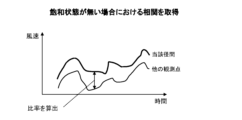
- FIG. 8A and 8B are schematic diagrams illustrating the second complementation method.
- the wind condition information providing device 100 obtains a correlation (here, the average value of the ratio between the actual value of the time change of the wind speed in the span) between the observed value of the time change of the wind speed at an observation point located near the span.
- the wind condition information providing device 100 obtains the wind speed in the saturation period of the span by multiplying the observed value in the saturation period at the observation point by the average value of the ratio.
- the method of obtaining the correlation is not necessarily limited, and the correlation may be obtained by other methods such as statistical methods or machine learning.
- the wind condition information providing device 100 includes a processor 101, a main storage device 102 (memory), an auxiliary storage device 103 (external storage device), an input device 104, an output device 105, a communication device 106, and an optical analysis unit 107. These are communicatively connected via a bus, a communication cable, or the like. Note that the wind condition information providing device 100 may be realized in whole or in part using virtual information processing resources, such as a virtual server provided by a cloud system.
- virtual information processing resources such as a virtual server provided by a cloud system.
- the processor 101 is configured using, for example, a CPU (Central Processing Unit), an MPU (Micro Processing Unit), a GPU (Graphics Processing Unit), an FPGA (Field Programmable Gate Array), an ASIC (Application Specific Integrated Circuit), an AI (Artificial Intelligence) chip, etc.
- a CPU Central Processing Unit
- MPU Micro Processing Unit
- GPU Graphics Processing Unit
- FPGA Field Programmable Gate Array
- ASIC Application Specific Integrated Circuit
- AI Artificial Intelligence
- the main memory device 102 is a memory device used by the processor 101 when executing a program, and is, for example, ROM (Read Only Memory), RAM (Random Access Memory), non-volatile memory (NVRAM (Non Volatile RAM)), etc.
- ROM Read Only Memory
- RAM Random Access Memory
- NVRAM Non Volatile RAM
- the auxiliary storage device 103 is a device that stores programs and data, and can be configured, for example, with an SSD (Solid State Drive), a hard disk drive, an optical storage device (CD (Compact Disc), DVD (Digital Versatile Disc), etc.). Programs and data can be read into the auxiliary storage device 103 from other information processing devices equipped with non-transient recording media or non-transient storage devices via a recording medium reading device or communication device 106. The programs and data stored (memorized) in the auxiliary storage device 103 are read into the main storage device 102 as needed.
- SSD Solid State Drive
- CD Compact Disc
- DVD Digital Versatile Disc
- the input device 104 is an interface that accepts information input from the outside, such as a keyboard, a mouse, a touch panel, or a voice input device.
- the output device 105 is an interface that outputs various information such as the progress of processing and the results of processing to the outside.
- the output device 105 is, for example, a display device (liquid crystal monitor, LCD (Liquid Crystal Display) etc.) that visualizes the various information described above, a device that converts the various information described above into audio (audio output device (speaker etc.)), or a device that converts the various information described above into text (printing device etc.).
- the information processing device 10 may be configured to input and output information between it and other devices via the communication device 106.
- the input device 104 and the output device 105 constitute a user interface that realizes interactive processing with the user (accepting information, providing information, etc.).
- the communication device 106 is a device that realizes communication with other devices via a communication network (such as a LAN (Local Area Network), WAN (Wide Area Network), the Internet, a public communication network, a dedicated line, etc.).
- the communication device 106 is a wired or wireless communication interface that realizes communication with other devices via a communication medium, such as a NIC (Network Interface Card), a wireless communication module, or a USB module (USB: Universal Serial Bus), etc.
- the optical analysis unit 107 is a device that uses a DAS to measure the vibration state of a measurement point, and includes a vibration measurement device using a C-OTDR and a signal processing circuit.
- the optical analysis unit 107 includes a CW (continuous wave) laser light source that generates an optical pulse (laser light) to be input to the end face of the optical fiber 4a, an optical pulse generator, an optical amplifier, optical equipment (optical detector, optical interferometer), a signal processing circuit (phase calculation circuit, etc.), etc.
- the optical analysis unit 107 and the optical fiber 4a are connected, for example, by optically connecting the output part of the laser light source of the optical analysis unit 107 to the connection port (socket) of the core wire of the OPGW installed in a substation, etc. Therefore, the connection does not cause any impact on the power system, such as a power outage.
- the wind condition information providing device 100 may be equipped with, for example, an operating system, a file system, a DBMS (Database Management System) (relational database, NoSQL, etc.), a KVS (Key-Value Store), etc.
- an operating system e.g., an operating system, a file system, a DBMS (Database Management System) (relational database, NoSQL, etc.), a KVS (Key-Value Store), etc.
- DBMS Database Management System
- NoSQL NoSQL, etc.
- KVS Key-Value Store
- the various functions of the wind condition information providing device 100 are realized by the processor 101 reading and executing programs stored in the main memory device 102, or by the hardware (FPGA, ASIC, AI chip, etc.) that constitutes the wind condition information providing device 100.
- the wind condition information providing device 100 stores various information (data), for example, as tables in a database or files managed by a file system.
- FIG. 9B is a block diagram showing the main functions of the wind condition information providing device 100.
- the wind condition information providing device 100 has the functions of a memory unit 110, a vibration state measurement unit 120, a span-by-span wind condition information generation unit 130, a saturation state determination unit 135, a complementary utilization information acquisition unit 140, a complementary processing unit 145, and a wind condition information providing unit 150.
- the memory unit 110 stores the vibration state for each measurement point 111, the model 112, the complementary use information 113, and the wind condition information for each span 114.
- the vibration state measurement unit 120 uses the DAS to measure the time change (time series data) of the vibration state at each measurement point, and manages the time change of the vibration state (vibration strength, vibration frequency) measured at each measurement point as the vibration state for each measurement point 111 by associating it with the identifier of each measurement point.
- the span-by-span wind condition information generating unit 130 acquires the vibration state of each span of the power transmission line 3 (the vibration state of each measurement point of each span) based on the vibration state of each measurement point of the measurement point vibration state 111, and inputs the acquired vibration state into the model 112 (the aforementioned model generated for each wind speed range and for each span) to acquire the time change in wind speed (time series data) in each span.
- the span-by-span wind condition information generating unit 130 manages the acquired time change in wind speed as span-by-span wind condition information 114, for example, by associating it with the identifier of each span or the identifier of each measurement point.
- the saturation state presence/absence determination unit 135 monitors the vibration state for each measurement point 111 in real time and determines whether or not the above-mentioned saturation period exists. Specifically, when a period in which the magnitude of the vibration intensity is equal to or greater than a preset threshold range continues for a preset threshold time or longer in the time change of the saturation determination component acquired from the vibration state for each measurement point 111, the saturation state presence/absence determination unit 135 determines that the period is a saturation period.
- the complementary use information acquisition unit 140 acquires information used to complement the wind speed during the saturation period, and manages the acquired information as complementary use information 113. For example, when the first complementary method described above is adopted, the complementary use information acquisition unit 140 acquires the actual values of the time change in wind speed for each of the first span and the second span described above. Also, when the second complementary method described above is adopted, the complementary use information acquisition unit 140 acquires the actual measured value of the time change in wind speed for the span, and the observed value of the time change in wind speed at an observation point located near the span.
- the complementation processing unit 145 uses the complementation utilization information 113 acquired by the complementation utilization information acquisition unit 140 to generate information for complementing the wind speed during the saturation period (estimated value of the wind speed during the saturation period). For example, when the first complementation method described above is adopted, the complementation processing unit 145 calculates the average value of the ratio based on the actual value of the time change of the wind speed in the span (the first span described above) and the actual value of the time change of the wind speed in the second span described above, and calculates the wind speed during the saturation period of the first span by multiplying the wind speed during the saturation period of the second span by the average value of the ratio.
- the complementation processing unit 145 calculates the average value of the ratio based on the actual value of the time change of the wind speed in the span and the observed value of the time change of the wind speed at an observation point near the span, and calculates the wind speed during the saturation period of the span by multiplying the observed value at the observation point by the average value of the ratio.
- the complementation processing unit 145 reflects the wind speed during the saturation period calculated as described above in the span-by-span wind condition information 114 (replaces the wind speed during the saturation period in the span-by-span wind condition information 114 with the wind speed during the saturation period calculated as described above).
- the wind condition information providing unit 150 provides the generated span-by-span wind condition information 114 to the wind condition information utilization device 300 (e.g., transmits it via a communication network).
- FIG. 10A is a schematic diagram explaining the process performed by the wind condition information providing device 100 (hereinafter referred to as "wind condition information providing process S1000")
- FIG. 10B is a flowchart explaining the wind condition information providing process S1000. Below, the wind condition information providing process S1000 will be explained with reference to these figures.
- the vibration state measurement unit 120 selects one span (S1011).
- the vibration state measurement unit 120 acquires the vibration state (vibration intensity, vibration frequency) of each measurement point of the selected span using the DAS, performs a fast Fourier transform (FFT) on the acquired vibration state of each measurement point, obtains the time change of the average vibration intensity for each frequency of each measurement point, and manages it as the vibration state for each measurement point 111 (S1012 to S1013).
- FFT fast Fourier transform
- the span-by-span wind condition information generating unit 130 calculates the time change in wind speed based on the time change in the wind condition estimation component of the selected span in the vibration state of each measurement point 111, and manages it as span-by-span wind condition information 114 (S1014).
- the saturation state determination unit 135 determines whether or not a saturation period is included in the time change of the saturation determination component of the selected span in the vibration state for each measurement point 111 (S1015). If a saturation period is included (S1015: Yes), the process proceeds to S1016. On the other hand, if a saturation period is not included (S1015: No), the process proceeds to S1017.
- the complementary use information acquisition unit 140 acquires the complementary use information 113.
- the complementary processing unit 145 also uses the complementary use information 113 to estimate the wind speed during the saturation period, for example, by the methods described above (first complementary method, second complementary method), and complements the wind speed during the saturation period of the span-by-span wind condition information 114.
- the wind condition information providing device 100 determines whether or not there is an unselected span in S1011. If there is an unselected span (S1017: Yes), the process returns to S1011. If there is no unselected span (S1017: No), the process proceeds to S1018.
- the wind condition information providing unit 150 transmits information based on the span-by-span wind condition information 114 to the wind condition information utilization device 300. This ends the wind condition information provision process S1000.
- the wind condition information providing system 1 of this embodiment it is possible to detect the presence of a saturation state in which the estimation accuracy of wind conditions based on vibration intensity decreases from the change over time in vibration intensity acquired by the DAS.
- the wind condition information system 1 detects saturation using saturation determination components in a higher frequency band than the frequency band of the wind condition estimation components, which are more likely to show characteristics of a saturated state among the vibration intensities acquired by the DAS, so it can detect saturation with high accuracy.
- the wind condition information providing system 1 complements the wind conditions during the saturation period using the first complementation method and the second complementation method, so it can provide the wind condition information utilization device 300 with stable and meaningful wind condition information.
- the saturation state determination unit 135 may determine whether or not a saturation state is present using a machine learning model that has been trained to output information indicating whether or not a saturation state is present as a target variable when feature quantities extracted by performing image recognition processing on the graphs (images) shown in Figures 6A and 6B are input as explanatory variables.
- Wind information system Power transmission tower 3 Power line 4 OPGW 4a Optical fiber 6
- Substation 100 Wind condition information providing device 107
- Optical analysis unit 110
- Storage unit 111
- Vibration state for each measurement point 112
- Model 113
- Complementary use information 114
- Wind condition information for each span 120
- Vibration state measurement unit 130
- Wind condition information for each span generation unit 135
- Saturation state presence/absence determination unit 140
- Complementary use information acquisition unit 145
- Complementary processing unit 150 Wind condition information providing unit S1000 Wind condition information provision processing
Landscapes
- Physics & Mathematics (AREA)
- General Physics & Mathematics (AREA)
- Engineering & Computer Science (AREA)
- Environmental & Geological Engineering (AREA)
- Aviation & Aerospace Engineering (AREA)
- Life Sciences & Earth Sciences (AREA)
- Atmospheric Sciences (AREA)
- Biodiversity & Conservation Biology (AREA)
- Ecology (AREA)
- Environmental Sciences (AREA)
- Indicating Or Recording The Presence, Absence, Or Direction Of Movement (AREA)
- Measurement Of Mechanical Vibrations Or Ultrasonic Waves (AREA)
Priority Applications (2)
| Application Number | Priority Date | Filing Date | Title |
|---|---|---|---|
| PCT/JP2023/035734 WO2025069410A1 (ja) | 2023-09-29 | 2023-09-29 | 風況情報提供システム、及び風況情報提供方法 |
| JP2024500685A JP7501812B1 (ja) | 2023-09-29 | 2023-09-29 | 風況情報提供システム、及び風況情報提供方法 |
Applications Claiming Priority (1)
| Application Number | Priority Date | Filing Date | Title |
|---|---|---|---|
| PCT/JP2023/035734 WO2025069410A1 (ja) | 2023-09-29 | 2023-09-29 | 風況情報提供システム、及び風況情報提供方法 |
Publications (1)
| Publication Number | Publication Date |
|---|---|
| WO2025069410A1 true WO2025069410A1 (ja) | 2025-04-03 |
Family
ID=91483413
Family Applications (1)
| Application Number | Title | Priority Date | Filing Date |
|---|---|---|---|
| PCT/JP2023/035734 Pending WO2025069410A1 (ja) | 2023-09-29 | 2023-09-29 | 風況情報提供システム、及び風況情報提供方法 |
Country Status (2)
| Country | Link |
|---|---|
| JP (1) | JP7501812B1 (https=) |
| WO (1) | WO2025069410A1 (https=) |
Citations (3)
| Publication number | Priority date | Publication date | Assignee | Title |
|---|---|---|---|---|
| WO2021171589A1 (ja) * | 2020-02-28 | 2021-09-02 | 日本電気株式会社 | 風速特定システム、風速特定装置、及び風速特定方法 |
| JP2022158078A (ja) * | 2021-04-01 | 2022-10-14 | 富士通株式会社 | 推定プログラム、推定方法、情報処理装置、および推定システム |
| JP2023050245A (ja) * | 2021-09-30 | 2023-04-11 | 富士通株式会社 | 推定プログラム、推定装置、及び推定方法 |
-
2023
- 2023-09-29 WO PCT/JP2023/035734 patent/WO2025069410A1/ja active Pending
- 2023-09-29 JP JP2024500685A patent/JP7501812B1/ja active Active
Patent Citations (3)
| Publication number | Priority date | Publication date | Assignee | Title |
|---|---|---|---|---|
| WO2021171589A1 (ja) * | 2020-02-28 | 2021-09-02 | 日本電気株式会社 | 風速特定システム、風速特定装置、及び風速特定方法 |
| JP2022158078A (ja) * | 2021-04-01 | 2022-10-14 | 富士通株式会社 | 推定プログラム、推定方法、情報処理装置、および推定システム |
| JP2023050245A (ja) * | 2021-09-30 | 2023-04-11 | 富士通株式会社 | 推定プログラム、推定装置、及び推定方法 |
Also Published As
| Publication number | Publication date |
|---|---|
| JP7501812B1 (ja) | 2024-06-18 |
| JPWO2025069410A1 (https=) | 2025-04-03 |
Similar Documents
| Publication | Publication Date | Title |
|---|---|---|
| WO2021077567A1 (zh) | 设备故障检测方法、设备故障检测装置及计算机存储介质 | |
| Zhang et al. | Event detection method comparison for distributed acoustic sensors using φ-OTDR | |
| CN114613116B (zh) | 防外破预警方法、装置、设备及存储介质 | |
| CN119251980A (zh) | 基于机器学习的光纤自然灾害预警方法及相关设备 | |
| JP7501812B1 (ja) | 風況情報提供システム、及び風況情報提供方法 | |
| CN118094719A (zh) | 一种铁路简支梁横隔板及支座损伤的评估方法及装置 | |
| JP7691003B2 (ja) | 判定装置、判定方法、およびプログラム | |
| US10742535B2 (en) | Monitoring a resource consumption of an application | |
| Manzato et al. | Removing the influence of rotor harmonics for improved monitoring of offshore wind turbines | |
| JP7464206B1 (ja) | 設備監視システム、及び設備監視方法 | |
| Erduran | Leveraging static bridge displacements for effective damage detection using vehicle-mounted sensors | |
| Allada et al. | An unsupervised learning algorithm for computer vision-based blind modal parameters identification of output-only structures from video measurements | |
| Song et al. | Nonstationary dynamic stochastic error analysis of fiber optic gyroscope based on optimized Allan variance | |
| Gao et al. | An experimental study on the identification of the root bolts' state of wind turbine blades using blade sensors | |
| CN113340226B (zh) | 输电线路杆塔的监测方法、装置、设备及介质 | |
| Kang et al. | Research on improving classification accuracy of cavitation intensity by sensor fusion | |
| JP7845110B2 (ja) | 電力設備の監視システム、及び監視方法 | |
| Falcone et al. | Use of Camera and AI for Mapping Monitoring for Architecture | |
| Huang et al. | Human intrusion detection with distributed fiber optic data based on Squeeze-Excitation and hierarchical connection enhancement network | |
| WO2025109652A1 (ja) | 設備監視システム、及び設備監視方法 | |
| JP7460042B1 (ja) | 災害発生予測システム、及び災害発生予測方法 | |
| JP7525082B1 (ja) | 設備監視システム、及び設備監視方法 | |
| CN121089778B (zh) | 光纤陀螺熔接点的间歇故障识别方法、设备、介质及产品 | |
| Bu et al. | Distributed OPGW abnormal vibration monitoring and forewarning based on LSTM | |
| CN114785414B (zh) | 光纤复合海缆外部声学干扰的识别方法及识别系统 |
Legal Events
| Date | Code | Title | Description |
|---|---|---|---|
| ENP | Entry into the national phase |
Ref document number: 2024500685 Country of ref document: JP Kind code of ref document: A |
|
| WWE | Wipo information: entry into national phase |
Ref document number: 2024500685 Country of ref document: JP |
|
| 121 | Ep: the epo has been informed by wipo that ep was designated in this application |
Ref document number: 23954377 Country of ref document: EP Kind code of ref document: A1 |