WO2025069217A1 - 超硬合金および切削工具 - Google Patents
超硬合金および切削工具 Download PDFInfo
- Publication number
- WO2025069217A1 WO2025069217A1 PCT/JP2023/035013 JP2023035013W WO2025069217A1 WO 2025069217 A1 WO2025069217 A1 WO 2025069217A1 JP 2023035013 W JP2023035013 W JP 2023035013W WO 2025069217 A1 WO2025069217 A1 WO 2025069217A1
- Authority
- WO
- WIPO (PCT)
- Prior art keywords
- cemented carbide
- binder phase
- hcp
- cobalt
- less
- Prior art date
- Legal status (The legal status is an assumption and is not a legal conclusion. Google has not performed a legal analysis and makes no representation as to the accuracy of the status listed.)
- Pending
Links
Images
Classifications
-
- C—CHEMISTRY; METALLURGY
- C22—METALLURGY; FERROUS OR NON-FERROUS ALLOYS; TREATMENT OF ALLOYS OR NON-FERROUS METALS
- C22C—ALLOYS
- C22C29/00—Alloys based on carbides, oxides, nitrides, borides, or silicides, e.g. cermets, or other metal compounds, e.g. oxynitrides, sulfides
- C22C29/02—Alloys based on carbides, oxides, nitrides, borides, or silicides, e.g. cermets, or other metal compounds, e.g. oxynitrides, sulfides based on carbides or carbonitrides
- C22C29/06—Alloys based on carbides, oxides, nitrides, borides, or silicides, e.g. cermets, or other metal compounds, e.g. oxynitrides, sulfides based on carbides or carbonitrides based on carbides, but not containing other metal compounds
- C22C29/08—Alloys based on carbides, oxides, nitrides, borides, or silicides, e.g. cermets, or other metal compounds, e.g. oxynitrides, sulfides based on carbides or carbonitrides based on carbides, but not containing other metal compounds based on tungsten carbide
Definitions
- Patent Document 1 cemented carbide alloys containing multiple tungsten carbide particles and a binder phase have been used as materials for cutting tools.
- the cemented carbide of the present disclosure is A cemented carbide comprising a plurality of tungsten carbide particles and a binder phase,
- the cemented carbide contains 89 volume % or more of the tungsten carbide particles and the binder phase in total,
- the cemented carbide contains 1.8% by volume or more and 20% by volume or less of the binder phase,
- the binder phase contains 80% by mass or more of cobalt,
- the cemented carbide includes an internal region having a distance from the surface of 300 ⁇ m or more; In the binder phase of the inner region, the percentage of the area S (hcp) of cobalt having hcp structure to the total area S (hcp) of cobalt having fcc structure S (fcc) ⁇ S (hcp) /(S (hcp) +S (fcc) ) ⁇ 100 is 45% or more.
- the percentage ⁇ S (hcp) /(S (hcp) +S (fcc) ) ⁇ 100 may be 50% or more and 70% or less, whereby the deformation resistance of the binder phase is improved, and a cutting tool including the cemented carbide can have a longer tool life.
- the binder phase may further contain at least one first element selected from the group consisting of silicon, phosphorus, germanium, tin, rhenium, ruthenium, osmium, iridium, and platinum. This improves the deformation resistance of the binder phase, and a cutting tool including the cemented carbide can have a longer tool life.
- the percentage of the mass M1 of the first element relative to the sum M1+M2 of the mass M1 of the first element and the mass M2 of cobalt, ⁇ M1/(M1+M2) ⁇ 100, may be 1% or more and 6% or less.
- the binder phase can have both superior hardness and superior toughness, so that a cutting tool including a cemented carbide containing the binder phase can have a longer tool life.
- the cutting tool of the present disclosure is a cutting tool having a cutting edge made of the cemented carbide alloy described in any one of (1) to (4) above.
- a ⁇ B means the upper and lower limits of a range (i.e., greater than or equal to A and less than or equal to B). If no unit is stated for A and only a unit is stated for B, the units of A and B are the same.
- any one numerical value listed as the lower limit and any one numerical value listed as the upper limit is also considered to be disclosed.
- a1 or more, b1 or more, and c1 or more are listed as the lower limit and a2 or less, b2 or less, and c2 or less are listed as the upper limit, a1 or more and a2 or less, a1 or more and b2 or less, a1 or more and c2 or less, b1 or more and a2 or less, b1 or more and b2 or less, b1 or more and c2 or less, c1 or more and a2 or less, c1 or more and b2 or less, and c1 or more and c2 or less are considered to be disclosed.
- the cemented carbide 3 according to one embodiment of the present disclosure (hereinafter also referred to as “embodiment 1”) is A cemented carbide (3) comprising a plurality of tungsten carbide particles (1) and a binder phase (2), The cemented carbide 3 contains tungsten carbide particles 1 and a binder phase 2 in a total amount of 89 volume % or more, The cemented carbide 3 contains a binder phase 2 of 1.8 volume % or more and 20 volume % or less, The binder phase 2 contains 80% by mass or more of cobalt, The cemented carbide 3 includes an internal region having a distance from the surface of 300 ⁇ m or more; In the binder phase of the internal region, the percentage of the area S (hcp) to the sum of the area S (hcp) of cobalt having the hcp structure and the area S (fcc) of co
- the cemented carbide of embodiment 1 can provide a cemented carbide that enables a longer tool life, particularly when used as a material for cutting tools for intermittent machining of high-strength materials, and a cutting tool equipped with the same.
- the reason for this is unclear, but is presumed to be as follows.
- the cemented carbide of the first embodiment comprises a plurality of tungsten carbide particles (hereinafter also referred to as "WC particles") and a binder phase, and the total content of the WC particles and binder phase in the cemented carbide is 89 volume % or more.
- WC particles tungsten carbide particles
- the cemented carbide has high hardness and strength, and a cutting tool comprising the cemented carbide can have excellent wear resistance and chipping resistance.
- the cemented carbide of embodiment 1 contains a binder phase of 1.8 volume % or more and 20 volume % or less, and the binder phase contains 80 mass % or more of cobalt.
- the cemented carbide has high hardness and strength, and a cutting tool including the cemented carbide can have excellent wear resistance and chipping resistance.
- the percentage of the area S (hcp) of the cobalt with hcp structure S ( hcp) and the area S (fcc) of the cobalt with fcc structure S (hcp ) is 45% or more.Therefore, the deformation resistance of binder phase is improved, and the deformation resistance of cemented carbide is improved.
- the cemented carbide of the first embodiment contains tungsten carbide particles and a binder phase in a total amount of 89% or more by volume. This can increase the hardness of the cemented carbide.
- the cemented carbide may contain tungsten carbide particles and a binder phase in a total amount of 89% to 100% by volume, 90% to 100% by volume, 91% to 100% by volume, or 92% to 100% by volume.
- the cemented carbide of embodiment 1 contains 1.8 volume % or more and 20 volume % or less of a binder phase. This allows the hardness and toughness of the cemented carbide to be increased.
- the content of the binder phase in the cemented carbide may be 2.0 volume % or more and 19.0 volume % or less, 3.0 volume % or more and 18.0 volume % or less, or 4.0 volume % or more and 17.0 volume % or less.
- the cemented carbide of embodiment 1 can be composed of a plurality of tungsten carbide particles and a binder phase.
- the cemented carbide can contain impurities to the extent that the effect of the present disclosure is not impaired.
- the cemented carbide may contain other phases (not shown) in addition to the tungsten carbide particles and the binder phase.
- the other phases may include carbides, nitrides or carbonitrides containing at least one element selected from the group consisting of titanium (Ti), tantalum (Ta), niobium (Nb), zirconium (Zr), hafnium (Hf) and molybdenum (Mo).
- the composition of the other phases may be, for example, at least one selected from the group consisting of TiCN, TaC, NbC, ZrC, HfC , Cr3C2 and Mo2C .
- the cemented carbide of embodiment 1 can be composed of tungsten carbide particles, a binder phase, and other phases.
- the cemented carbide can contain impurities to the extent that the effects of the present disclosure are not impaired.
- the content of other phases in the cemented carbide is permissible within a range that does not impair the effects of the present disclosure.
- the content of other phases in the cemented carbide may be 0 vol.% or more and 11 vol.% or less, more than 0 vol.% and 11 vol.% or less, more than 0 vol.% and 7 vol.% or less, or more than 0 vol.% and 4 vol.% or less.
- the cemented carbide of the first embodiment may contain impurities.
- impurities include iron (Fe), calcium (Ca), silicon (Si), and sulfur (S).
- the impurity content of the cemented carbide is acceptable within a range that does not impair the effects of the present disclosure.
- the impurity content of the cemented carbide may be 0 mass% or more and less than 0.1 mass%.
- the impurity content of the cemented carbide is measured by ICP optical emission spectroscopy (Inductively Coupled Plasma Emission Spectroscopy). The measuring device that can be used is Shimadzu Corporation's "ICPS-8100" (trademark).
- the tungsten carbide particle content of the cemented carbide of embodiment 1 may be 67% by volume or more and 98.2% by volume or less, 70% by volume or more and 97% by volume or less, or 75% by volume or more and 96% by volume or less.
- the method for measuring the tungsten carbide particle content (volume %) of the cemented carbide and the binder phase content (volume %) of the cemented carbide is as follows.
- the mirror-finished surface of the cemented carbide is photographed with a scanning electron microscope (SEM) to obtain a backscattered electron image.
- the photographed area is set to the center of the cross section of the cemented carbide, that is, a position that does not include areas with properties that are clearly different from the bulk part, such as near the surface of the cemented carbide (a position where the entire photographed area is the bulk part of the cemented carbide).
- the observation magnification is 5000x.
- the measurement conditions are an acceleration voltage of 3 kV, a current value of 2 nA, and a working distance (WD) of 5 mm.
- (H1) The measurement of (G1) above is performed in five different non-overlapping measurement fields.
- the average of the area percentages of tungsten carbide particles in the five measurement fields corresponds to the content (volume %) of tungsten carbide particles in the cemented carbide
- the average of the area percentages of the binder phase in the five measurement fields corresponds to the content (volume %) of the binder phase in the cemented carbide.
- the content of the other phases in the cemented carbide can be obtained by subtracting the content (volume %) of the tungsten carbide grains and the content (volume %) of the binder phase measured by the above procedure from the total cemented carbide (100 volume %).
- the cemented carbide of embodiment 1 may contain 1% by mass or more of cobalt.
- the cobalt content of the cemented carbide may be 1.0% by mass or more and 20% by mass or less, 2.0% by mass or more and 15% by mass or less, or 3.0% by mass or more and 12% by mass or less.
- the method for measuring the cobalt content of the cemented carbide is as follows. Using the same method as (A1) to (D1) of the method for measuring the tungsten carbide particle content and binder phase content of the cemented carbide, an element mapping image is obtained by performing analysis using SEM-EDX. Based on the element mapping image, the cobalt region in the cemented carbide is identified and the cobalt content is measured. The measurement is performed in five different, non-overlapping imaging regions. In the present disclosure, the average of the cobalt content in the five imaging regions corresponds to the cobalt content of the cemented carbide.
- the tungsten carbide particles include at least one of "pure WC particles (including WC containing no impurity elements and WC containing impurity elements below the detection limit)" and "WC particles containing impurity elements intentionally or unavoidably, as long as the effect of the present disclosure is not impaired.”
- the impurity content of the tungsten carbide particles (when the impurity elements are two or more types, the total concentration of the elements) is less than 0.1 mass%.
- the impurity element content of the tungsten carbide particles is measured by ICP emission spectrometry.
- the average particle size of the tungsten carbide particles is not particularly limited.
- the average particle size of the tungsten carbide particles can be, for example, 0.1 ⁇ m or more and 3.5 ⁇ m or less. It has been confirmed that the cemented carbide of the first embodiment enables the tool to have a longer life when used as a material for cutting tools, regardless of the average particle size of the tungsten carbide particles.
- the binder phase contains 80% by mass or more of cobalt. This allows the cemented carbide to have excellent toughness.
- the cobalt content of the binder phase may be 80% by mass or more and 100% by mass or less, 80% by mass or more and less than 100% by mass, or 90% by mass or more and less than 100% by mass.
- the method for measuring the cobalt content of the binder phase is as follows.
- An element mapping image and an image after binarization are obtained by the same method as (A1) to (E1) of the above-mentioned method for measuring the tungsten carbide particle content and binder phase content of the cemented carbide.
- the element mapping image and the image after binarization are superimposed to identify the region in which the binder phase exists in the element mapping image.
- a rectangular measurement field of view of 24.9 ⁇ m ⁇ 18.8 ⁇ m is set in the element mapping image.
- the cobalt content is measured in the region in which the binder phase exists in the measurement field.
- the above measurement is performed in five different measurement fields that do not overlap each other.
- the average of the cobalt contents in the regions in which the binder phase exists in the five measurement fields corresponds to the cobalt content of the binder phase.
- the binder phase may further contain at least one first element selected from the group consisting of silicon, phosphorus, germanium, tin, rhenium, ruthenium, osmium, iridium, and platinum. This improves the deformation resistance of the binder phase.
- the inclusion of the first element in the binder phase is confirmed by the following procedure.
- An element mapping image and an image after binarization are obtained by the same method as (A1) to (E1) of the above-mentioned method for measuring the tungsten carbide particle content and binder phase content of cemented carbide.
- the region in which the binder phase exists is identified in the element mapping image. If the first element is present in the region in which the binder phase exists in the element mapping, it is confirmed that the binder phase contains the first element.
- the percentage ⁇ M1/(M1+M2) ⁇ 100 of the mass of the first element M1 relative to the sum M1+M2 of the mass of the first element M1 and the mass of cobalt M2 may be 1% or more and 6% or less.
- the units of M1 and M2 are the same.
- the binder phase can have both better hardness and better toughness, so that a cutting tool including a cemented carbide containing the binder phase can have a longer tool life.
- the mass M1 of the first element means the total mass of all types of first elements when the binder phase contains two or more types of first elements.
- the percentage ⁇ M1/(M1+M2) ⁇ 100 may be 2% or more and 5% or less, or 3% or more and 4% or less.
- the method for measuring the percentage ⁇ M1/(M1+M2) ⁇ x 100 is as follows.
- An element mapping image and an image after binarization are obtained by the same method as (A1) to (E1) of the method for measuring the tungsten carbide particle content and binder phase content of the cemented carbide.
- the element mapping image and the image after binarization are superimposed to identify the region in which the binder phase exists in the element mapping image.
- a rectangular measurement field of view of 24.9 ⁇ m x 18.8 ⁇ m is set in the element mapping image.
- the percentage ⁇ m1/(m1+m2) ⁇ x 100 of the mass m1 of the first element relative to the sum m1+m2 of the mass m1 of the first element and the mass m2 of cobalt is calculated.
- the above measurement is performed in five different measurement fields that do not overlap with each other.
- the average of the percentage ⁇ m1/(m1+m2) ⁇ x 100 in the five measurement fields corresponds to the "percentage ⁇ M1/(M1+M2) ⁇ x 100" in the binder phase of the cemented carbide.
- the binder phase can contain, in addition to cobalt and the first element, at least one second element selected from the group consisting of iron, nickel, and chromium.
- the binder phase can consist of cobalt, the first element, and the second element.
- the binder phase can consist of cobalt, the first element, the second element, and unavoidable impurities. Examples of the unavoidable impurities include iron, nickel, and sulfur.
- the cemented carbide of embodiment 1 comprises an inner region that is 300 ⁇ m or more away from the surface, and in the binding phase of the inner region, the percentage of the area S (hcp) of the cobalt having hcp (hexagonal close-packed) structure S (hcp ) and the area S (fcc) of the cobalt having fcc (face-centered cubic) structure S ( hcp ) is 45% or more.
- This percentage ⁇ S (hcp) / (S (hcp) + S (fcc) ) ⁇ ⁇ 100 can be 45% or more and 80% or less, or can be 50% or more and 70% or less.
- the percentage of binder phase in the internal region of a cemented carbide ⁇ S (hcp) /(S (hcp) +S (fcc) ) ⁇ 100 is measured by the following procedure.
- the cemented carbide is cut out along the normal to its main surface to expose the cross section. If the surface of the cemented carbide does not have a flat area, the cemented carbide is cut out from any point on the surface in a direction toward the center of gravity of the cemented carbide to expose the cross section.
- the cross section is mirror-finished using a cross-section polisher (manufactured by JEOL Ltd.).
- the mirror-finished surface of the cemented carbide is observed using a scanning electron microscope (SEM: Carl Zeiss Gemini450 (trademark)) equipped with an electron backscatter diffraction (EBSD (Electron Backscatter Diffraction Pattern) device: Oxford Symmetry (trademark).
- EBSD analysis is performed on the obtained observation image.
- the observation image is acquired so as to include an internal region that is 300 ⁇ m or more away from the surface of the cemented carbide.
- a rectangular measurement field of view of 11.5 ⁇ m x 8.5 ⁇ m is set in the internal region of the observation image.
- the observation magnification is 10,000 times.
- the measurement conditions are an acceleration voltage of 15 kV, a current value of 20 nA, 0.02 ⁇ m/step, an exposure time of 1.5 to 3 ms, and a measurement time of 10 to 20 minutes.
- the EBSD analysis results are analyzed using commercially available software (AZtecCrystal (trademark) manufactured by Oxford), the crystal structure of the cobalt contained in the binder phase is identified in the above measurement field of view, and a color map is obtained.
- the crystal structure of the cobalt identified here is the crystal structure observed when the cobalt appearing on the mirror-finished surface of the cemented carbide is viewed in a planar view from the normal direction of the mirror-finished surface.
- the cemented carbide of embodiment 1 may include a surface region that is less than 300 ⁇ m away from the surface.
- the percentage ⁇ S (hcp) / (S (hcp) + S (fcc) ) ⁇ ⁇ 100 of the binder phase of the surface region of the cemented carbide of embodiment 1 is not particularly limited. This is because the surface region of the cemented carbide is affected by the stress during grinding when the cutting edge of the cutting tool made of the cemented carbide is formed by grinding, so it is not the essential part of the cemented carbide that directly affects the life of the cutting tool.
- the inner region of the cemented carbide that is 300 ⁇ m or more away from the surface is not easily subjected to stress when the cutting edge of the cutting tool is formed by grinding, so it is the essential part of the cemented carbide that affects the life of the cutting tool. Therefore, in the cemented carbide of the present disclosure, the percentage ⁇ S (hcp) / (S ( hcp) + S (fcc) ) ⁇ ⁇ 100 of the binder phase of the inner region is specified.
- the percentage ⁇ S (hcp) /(S (hcp) +S (fcc) ) ⁇ 100 in the binder phase in the surface region of the cemented carbide of embodiment 1 may, for example, be less than 45%.
- the cemented carbide of the first embodiment can be manufactured by carrying out the steps of preparing raw material powder, mixing, molding, and sintering in the above-mentioned order. Each step will be described below.
- the preparation step is a step of preparing a raw material powder of the cemented carbide.
- the raw material powder include tungsten carbide powder (hereinafter also referred to as "WC powder"), cobalt (Co) powder, first element powder, and alloy powder of the first element and cobalt.
- the first element powder include silicon (Si) powder, phosphorus (P) powder, germanium (Ge) powder, tin (Sn) powder, rhenium (Re) powder, ruthenium (Ru) powder, osmium (Os) powder, iridium (Ir) powder, and platinum (Pt) powder.
- the raw material powder examples include nickel (Ni) powder, niobium carbide (NbC) powder, tungsten carbide (TaC) powder, titanium carbonitride (TiCN) powder, and chromium carbide (Cr 3 C 2 ) powder. These raw material powders can be commercially available.
- the average particle size of these raw material powders is not particularly limited and can be, for example, 0.5 to 2 ⁇ m.
- the average particle size of the raw material powder means the average particle size measured by the FSSS (Fisher Sub-Sieve Sizer) method. The average particle size is measured using a "Sub-Sieve Sizer Model 95" (trademark) manufactured by Fisher Scientific.
- the mixing step is a step of mixing the raw material powders prepared in the preparation step in a predetermined ratio.
- a mixed powder in which the raw material powders are mixed is obtained by the mixing step.
- the mixing ratio of the raw material powders is appropriately adjusted depending on the composition of the target cemented carbide.
- the raw material powders can be mixed using conventional mixing methods such as an attritor, ball mill, or bead mill. Conventional mixing conditions can also be used.
- the mixing time can be, for example, 2 hours or more and 20 hours or less.
- the mixed powder may be granulated as necessary. Granulating the mixed powder makes it easier to fill the mixed powder into a die or mold during the molding step described below.
- a known granulation method can be used for granulation, and for example, a commercially available granulator such as a spray dryer can be used.
- the molding step is a step of molding the mixed powder obtained in the mixing step into a shape for a cutting tool to obtain a molded body.
- the molding method and molding conditions in the molding step are not particularly limited and may be general methods and conditions.
- the sintering step is a step of sintering the compact obtained in the compacting step to obtain a cemented carbide intermediate body. Specifically, the compact is held under conditions of 7 MPa and 1360° C. for 2 hours.
- the cooling step is a step of cooling the cemented carbide intermediate body after the sintering step. Specifically, the cemented carbide intermediate body is cooled to 1200°C in a vacuum and held for 30 minutes. Then, the cemented carbide intermediate body is slowly cooled to 1000°C in a vacuum at a temperature drop rate of -0.5°C/min. Then, the cemented carbide intermediate body is quenched to room temperature (23°C) in a vacuum at a temperature drop rate of -20°C/min to obtain the cemented carbide of the first embodiment.
- the sintering step is performed by holding the cemented carbide intermediate body under conditions of 7 MPa and 1360°C for 2 hours.
- the cemented carbide intermediate body is cooled in a vacuum to 1200°C and held for 30 minutes, and then the cemented carbide intermediate body is gradually cooled in a vacuum to 1000°C at a temperature drop rate of -0.5°C/min, and then the cemented carbide intermediate body is quenched in a vacuum to room temperature (23°C) at a temperature drop rate of -20°C/min.
- the cemented carbide according to the first embodiment can be produced in which the percentage ⁇ S (hcp) /(S (hcp) +S (fcc) ) ⁇ 100 in the binder phase in the internal region of the cemented carbide is 45% or more.
- the present inventors have found, as a result of intensive research, that the cemented carbide according to the present disclosure can be realized by adopting such a sintering step and a cooling step.
- a cutting tool according to an embodiment of the present disclosure includes a cutting edge made of the cemented carbide of embodiment 1.
- the cutting edge refers to a portion involved in cutting. More specifically, the cutting edge refers to a region surrounded by a cutting edge ridge and a virtual surface that is 0.5 mm or 2 mm away from the cutting edge ridge toward the cemented carbide side.
- Cutting tools include, for example, cutting tools, drills, end mills, indexable cutting tips for milling, indexable cutting tips for turning, metal saws, gear cutting tools, reamers, taps, etc.
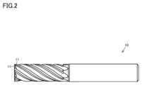
- the cutting tool 10 of the second embodiment can exhibit excellent effects, particularly in the case of an end mill.
- the cutting edge 11 of the cutting tool 10 shown in FIG. 2 is made of the cemented carbide of the first embodiment.
- the cemented carbide of embodiment 1 may constitute the entire tool or may constitute only a part of the tool.
- "constitute a part” refers to a mode in which the cemented carbide of embodiment 1 is brazed to a predetermined position of any substrate to form a cutting edge.
- the cutting tool of the second embodiment may further include a hard film that covers at least a portion of the surface of the substrate made of cemented carbide.
- the hard film may be made of, for example, diamond-like carbon or diamond.
- the cutting tool of embodiment 2 can be obtained by forming the cemented carbide of embodiment 1 into a desired shape.
- silicon (Si) powder (average particle size: 1 ⁇ m), phosphorus (P) powder (average particle size: 1 ⁇ m), germanium (Ge) powder (average particle size: 1 ⁇ m), tin (Sn) powder (average particle size: 1 ⁇ m), rhenium (Re) powder (average particle size: 1 ⁇ m), ruthenium (Ru) powder (average particle size: 1 ⁇ m), osmium (Os) powder (average particle size: 1 ⁇ m), iridium (Ir) powder (average particle size: 1 ⁇ m), and platinum (Pt) powder (average particle size: 1 ⁇ m) were prepared.
- ⁇ Mixing step> A mixed powder was obtained by mixing the raw material powders for 10 hours using an attritor in the ratios shown in Table 1.
- the ratio (mass %) of each raw material powder shown in Table 1 is the ratio when the total mixed powder is taken as 100 mass %.
- the cemented carbide intermediates were quenched in a vacuum to room temperature (23°C) at a temperature drop rate of -20°C/min (described in the "Temperature Drop Rate to 23°C” column of Table 2) to obtain the cemented carbide of each sample.
- the cemented carbide intermediate body after the sintering process was rapidly cooled in a vacuum to room temperature (23°C) at a cooling rate of -20°C/min (shown in the "Cooling rate to 23°C” column in Table 2) to obtain the cemented carbide samples.
- the cemented carbide and cutting tools of Samples 1 to 16 correspond to Examples.
- the cemented carbide and cutting tools of Samples 101 to 107 correspond to Comparative Examples. It was confirmed that the cutting tools of Samples 1 to 16 had longer tool lives than the cutting tools of Samples 101 to 107.
Landscapes
- Chemical & Material Sciences (AREA)
- Engineering & Computer Science (AREA)
- Materials Engineering (AREA)
- Mechanical Engineering (AREA)
- Metallurgy (AREA)
- Organic Chemistry (AREA)
- Cutting Tools, Boring Holders, And Turrets (AREA)
- Powder Metallurgy (AREA)
Priority Applications (4)
| Application Number | Priority Date | Filing Date | Title |
|---|---|---|---|
| PCT/JP2023/035013 WO2025069217A1 (ja) | 2023-09-26 | 2023-09-26 | 超硬合金および切削工具 |
| CN202380100059.5A CN121464232A (zh) | 2023-09-26 | 2023-09-26 | 硬质合金以及切削工具 |
| JP2024529595A JP7666744B1 (ja) | 2023-09-26 | 2023-09-26 | 超硬合金および切削工具 |
| TW113129376A TW202513819A (zh) | 2023-09-26 | 2024-08-06 | 超硬合金及切削工具 |
Applications Claiming Priority (1)
| Application Number | Priority Date | Filing Date | Title |
|---|---|---|---|
| PCT/JP2023/035013 WO2025069217A1 (ja) | 2023-09-26 | 2023-09-26 | 超硬合金および切削工具 |
Publications (1)
| Publication Number | Publication Date |
|---|---|
| WO2025069217A1 true WO2025069217A1 (ja) | 2025-04-03 |
Family
ID=95202512
Family Applications (1)
| Application Number | Title | Priority Date | Filing Date |
|---|---|---|---|
| PCT/JP2023/035013 Pending WO2025069217A1 (ja) | 2023-09-26 | 2023-09-26 | 超硬合金および切削工具 |
Country Status (4)
| Country | Link |
|---|---|
| JP (1) | JP7666744B1 (https=) |
| CN (1) | CN121464232A (https=) |
| TW (1) | TW202513819A (https=) |
| WO (1) | WO2025069217A1 (https=) |
Citations (4)
| Publication number | Priority date | Publication date | Assignee | Title |
|---|---|---|---|---|
| JP2004131769A (ja) | 2002-10-09 | 2004-04-30 | Toshiba Tungaloy Co Ltd | 超微粒超硬合金 |
| JP2019063932A (ja) * | 2017-09-29 | 2019-04-25 | 三菱マテリアル株式会社 | 耐溶着チッピング性にすぐれた切削工具 |
| JP2019063937A (ja) * | 2017-09-29 | 2019-04-25 | 三菱マテリアル株式会社 | 耐溶着チッピング性にすぐれた表面被覆切削工具 |
| JP2020504780A (ja) * | 2016-12-20 | 2020-02-13 | サンドビック インテレクチュアル プロパティー アクティエボラーグ | 切削工具 |
-
2023
- 2023-09-26 WO PCT/JP2023/035013 patent/WO2025069217A1/ja active Pending
- 2023-09-26 JP JP2024529595A patent/JP7666744B1/ja active Active
- 2023-09-26 CN CN202380100059.5A patent/CN121464232A/zh active Pending
-
2024
- 2024-08-06 TW TW113129376A patent/TW202513819A/zh unknown
Patent Citations (4)
| Publication number | Priority date | Publication date | Assignee | Title |
|---|---|---|---|---|
| JP2004131769A (ja) | 2002-10-09 | 2004-04-30 | Toshiba Tungaloy Co Ltd | 超微粒超硬合金 |
| JP2020504780A (ja) * | 2016-12-20 | 2020-02-13 | サンドビック インテレクチュアル プロパティー アクティエボラーグ | 切削工具 |
| JP2019063932A (ja) * | 2017-09-29 | 2019-04-25 | 三菱マテリアル株式会社 | 耐溶着チッピング性にすぐれた切削工具 |
| JP2019063937A (ja) * | 2017-09-29 | 2019-04-25 | 三菱マテリアル株式会社 | 耐溶着チッピング性にすぐれた表面被覆切削工具 |
Also Published As
| Publication number | Publication date |
|---|---|
| JP7666744B1 (ja) | 2025-04-22 |
| TW202513819A (zh) | 2025-04-01 |
| CN121464232A (zh) | 2026-02-03 |
| JPWO2025069217A1 (https=) | 2025-04-03 |
Similar Documents
| Publication | Publication Date | Title |
|---|---|---|
| US11858049B2 (en) | Cemented carbide and tool containing the same | |
| JP7666745B1 (ja) | 超硬合金および切削工具 | |
| JP7666744B1 (ja) | 超硬合金および切削工具 | |
| JP7694819B1 (ja) | 超硬合金 | |
| JP7694813B1 (ja) | 超硬合金 | |
| JP7694812B1 (ja) | 超硬合金 | |
| JP7694811B1 (ja) | 超硬合金 | |
| JP7670234B1 (ja) | 超硬合金および切削工具 | |
| JP7501800B1 (ja) | 超硬合金およびそれを用いた切削工具 | |
| JP7589840B1 (ja) | 超硬合金および切削工具 | |
| WO2026088289A1 (ja) | 超硬合金および切削工具 | |
| JP7782778B1 (ja) | 超硬合金および切削工具 | |
| JP7786662B1 (ja) | 超硬合金および切削工具 | |
| WO2026088288A1 (ja) | 超硬合金および切削工具 | |
| JP2025076775A (ja) | 超硬合金および切削工具 | |
| WO2026088290A1 (ja) | 超硬合金および切削工具 | |
| TW202613330A (zh) | 超硬合金及切削工具 | |
| TW202607158A (zh) | 超硬合金及切削工具 | |
| WO2026033732A1 (ja) | 超硬合金および切削工具 | |
| WO2025027677A1 (ja) | 超硬合金および切削工具 |
Legal Events
| Date | Code | Title | Description |
|---|---|---|---|
| ENP | Entry into the national phase |
Ref document number: 2024529595 Country of ref document: JP Kind code of ref document: A |
|
| WWE | Wipo information: entry into national phase |
Ref document number: 2024529595 Country of ref document: JP |
|
| 121 | Ep: the epo has been informed by wipo that ep was designated in this application |
Ref document number: 23954193 Country of ref document: EP Kind code of ref document: A1 |