WO2025069216A1 - 超硬合金 - Google Patents
超硬合金 Download PDFInfo
- Publication number
- WO2025069216A1 WO2025069216A1 PCT/JP2023/035012 JP2023035012W WO2025069216A1 WO 2025069216 A1 WO2025069216 A1 WO 2025069216A1 JP 2023035012 W JP2023035012 W JP 2023035012W WO 2025069216 A1 WO2025069216 A1 WO 2025069216A1
- Authority
- WO
- WIPO (PCT)
- Prior art keywords
- cemented carbide
- binder phase
- mass
- less
- content
- Prior art date
- Legal status (The legal status is an assumption and is not a legal conclusion. Google has not performed a legal analysis and makes no representation as to the accuracy of the status listed.)
- Pending
Links
Images
Classifications
-
- C—CHEMISTRY; METALLURGY
- C22—METALLURGY; FERROUS OR NON-FERROUS ALLOYS; TREATMENT OF ALLOYS OR NON-FERROUS METALS
- C22C—ALLOYS
- C22C29/00—Alloys based on carbides, oxides, nitrides, borides, or silicides, e.g. cermets, or other metal compounds, e.g. oxynitrides, sulfides
- C22C29/02—Alloys based on carbides, oxides, nitrides, borides, or silicides, e.g. cermets, or other metal compounds, e.g. oxynitrides, sulfides based on carbides or carbonitrides
- C22C29/06—Alloys based on carbides, oxides, nitrides, borides, or silicides, e.g. cermets, or other metal compounds, e.g. oxynitrides, sulfides based on carbides or carbonitrides based on carbides, but not containing other metal compounds
- C22C29/067—Alloys based on carbides, oxides, nitrides, borides, or silicides, e.g. cermets, or other metal compounds, e.g. oxynitrides, sulfides based on carbides or carbonitrides based on carbides, but not containing other metal compounds comprising a particular metallic binder
-
- C—CHEMISTRY; METALLURGY
- C22—METALLURGY; FERROUS OR NON-FERROUS ALLOYS; TREATMENT OF ALLOYS OR NON-FERROUS METALS
- C22C—ALLOYS
- C22C29/00—Alloys based on carbides, oxides, nitrides, borides, or silicides, e.g. cermets, or other metal compounds, e.g. oxynitrides, sulfides
- C22C29/02—Alloys based on carbides, oxides, nitrides, borides, or silicides, e.g. cermets, or other metal compounds, e.g. oxynitrides, sulfides based on carbides or carbonitrides
- C22C29/06—Alloys based on carbides, oxides, nitrides, borides, or silicides, e.g. cermets, or other metal compounds, e.g. oxynitrides, sulfides based on carbides or carbonitrides based on carbides, but not containing other metal compounds
- C22C29/08—Alloys based on carbides, oxides, nitrides, borides, or silicides, e.g. cermets, or other metal compounds, e.g. oxynitrides, sulfides based on carbides or carbonitrides based on carbides, but not containing other metal compounds based on tungsten carbide
-
- B—PERFORMING OPERATIONS; TRANSPORTING
- B22—CASTING; POWDER METALLURGY
- B22F—WORKING METALLIC POWDER; MANUFACTURE OF ARTICLES FROM METALLIC POWDER; MAKING METALLIC POWDER; APPARATUS OR DEVICES SPECIALLY ADAPTED FOR METALLIC POWDER
- B22F5/00—Manufacture of workpieces or articles from metallic powder characterised by the special shape of the product
- B22F2005/001—Cutting tools, earth boring or grinding tool other than table ware
-
- B—PERFORMING OPERATIONS; TRANSPORTING
- B22—CASTING; POWDER METALLURGY
- B22F—WORKING METALLIC POWDER; MANUFACTURE OF ARTICLES FROM METALLIC POWDER; MAKING METALLIC POWDER; APPARATUS OR DEVICES SPECIALLY ADAPTED FOR METALLIC POWDER
- B22F9/00—Making metallic powder or suspensions thereof
- B22F9/02—Making metallic powder or suspensions thereof using physical processes
- B22F9/026—Spray drying of solutions or suspensions
-
- C—CHEMISTRY; METALLURGY
- C22—METALLURGY; FERROUS OR NON-FERROUS ALLOYS; TREATMENT OF ALLOYS OR NON-FERROUS METALS
- C22C—ALLOYS
- C22C1/00—Making non-ferrous alloys
- C22C1/04—Making non-ferrous alloys by powder metallurgy
- C22C1/05—Mixtures of metal powder with non-metallic powder
- C22C1/051—Making hard metals based on borides, carbides, nitrides, oxides or silicides; Preparation of the powder mixture used as the starting material therefor
Definitions
- This disclosure relates to cemented carbide.
- Patent Document 1 cemented carbide alloys containing multiple tungsten carbide particles and a binder phase have been used as materials for cutting tools.
- the cemented carbide of the present disclosure is A cemented carbide comprising a plurality of tungsten carbide particles and a binder phase,
- the cemented carbide comprises 89 volume % or more of the tungsten carbide particles and the binder phase in total,
- the cemented carbide contains 1.8 vol. % or more and 20.0 vol. % or less of the binder phase, the binder phase comprises cobalt;
- the cemented carbide contains 1.0 mass% or more of cobalt,
- the percentage (Y2/Y1) ⁇ 100 of the Young's modulus Y2GPa at 600° C. to the Young's modulus Y1GPa at 25° C. measured by a nanoindenter method of the binder phase is 50% or more.
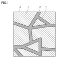
- FIG. 1 is a diagram illustrating a cross section of a cemented carbide according to an embodiment of the present disclosure.
- the present disclosure therefore aims to provide a cemented carbide alloy that enables a longer tool life, especially when used as a material for cutting tools for high-speed machining of difficult-to-cut materials with high tensile strength.
- the percentage (Y2/Y1) x 100 may be 70% or more. This makes it possible to provide a cemented carbide that can further extend the tool life of cutting tools, especially in high-speed machining of difficult-to-cut materials with high tensile strength.
- the Young's modulus Y1 may be 170 GPa or more. This makes it possible to provide a cemented carbide that can further extend the tool life of cutting tools, especially in high-speed machining of difficult-to-cut materials with high tensile strength.
- the percentage of the mass M1 of the first element in the binder phase relative to the sum M1+M2 of the mass M1 of the first element and the mass M2 of cobalt, ⁇ M1/(M1+M2) ⁇ 100, may be 1% or more and 6% or less. This makes it possible to provide a cemented carbide alloy that can further extend the tool life of cutting tools, especially in high-speed machining of difficult-to-cut materials with high tensile strength.
- a ⁇ B means the upper and lower limits of a range (i.e., greater than or equal to A and less than or equal to B). If no unit is stated for A and only a unit is stated for B, the units of A and B are the same.
- a cemented carbide according to one embodiment of the present disclosure will be described with reference to FIG.
- One embodiment of the present disclosure (hereinafter also referred to as "the present embodiment") is A cemented carbide (3) comprising a plurality of tungsten carbide particles (1) and a binder phase (2),
- the cemented carbide 3 contains the tungsten carbide particles 1 and the binder phase 2 in a total amount of 89 volume % or more,
- the cemented carbide 3 contains the binder phase 2 in an amount of 1.8 vol.% or more and 20.0 vol.% or less,
- the binder phase 2 contains cobalt,
- the cemented carbide 3 contains 1.0 mass% or more of cobalt,
- the percentage (Y2/Y1) ⁇ 100 of the Young's modulus Y2GPa at 600° C. to the Young's modulus Y1GPa at 25° C. measured by a nanoindenter method of the binder phase 2 is 50% or more.
- the cemented carbide 3 of this embodiment comprises a plurality of tungsten carbide particles 1 (hereinafter also referred to as "WC particles 1") and a binder phase 2, and the total content of the WC particles 1 and the binder phase 2 in the cemented carbide 3 is 89 volume % or more.
- WC particles 1 tungsten carbide particles 1
- binder phase 2 the total content of the WC particles 1 and the binder phase 2 in the cemented carbide 3 is 89 volume % or more.
- the cemented carbide 3 of the first embodiment contains 1.8 volume % or more and 20.0 volume % or less of the binder phase 2, the binder phase 2 contains cobalt, and the cemented carbide 3 contains 1.0 mass % or more of cobalt. Furthermore, the percentage (Y2/Y1) x 100 of the Young's modulus Y2GPa at 600°C to the Young's modulus Y1GPa at 25°C measured by the nanoindenter method of the binder phase 2 is 50% or more, and the "decrease in the Young's modulus of the cemented carbide 3" caused by changing from the condition of 25°C (in other words, the room temperature condition) to the condition of 600°C (in other words, the high temperature condition) can be suppressed.
- the "decrease in the Young's modulus of the cemented carbide 3" is suppressed, and the cutting tool using the cemented carbide 3 can have excellent chipping resistance, especially in high-speed machining of difficult-to-cut materials with high tensile strength.
- the cemented carbide 3 may contain tungsten carbide particles 1 and binder phase 2 in a total amount of 90% or more by volume and 100% or less by volume, 91% or more by volume and 100% or less by volume, or 92% or more by volume and 100% or less by volume.
- the cemented carbide 3 contains 1.8 vol.% or more and 20.0 vol.% or less of the binder phase 2. This allows the cemented carbide 3 to have an increased Young's modulus and toughness.
- the lower limit of the content of the binder phase 2 in the cemented carbide 3 may be 2.0 vol.% or more, 3.0 vol.% or more, or 4.0 vol.% or more.
- the upper limit of the content of the binder phase 2 in the cemented carbide 3 may be 19.0 vol.% or less, 18.0 vol.% or less, or 17.0 vol.% or less.
- the cemented carbide 3 may contain 2.0 vol.% or more and 19.0 vol.% or less of the binder phase 2, 3.0 vol.% or more and 18.0 vol.% or less of the binder phase 2, or 4.0 vol.% or more and 17.0 vol.% or less of the binder phase 2.
- the cemented carbide 3 of the first embodiment can be composed of a plurality of tungsten carbide particles 1 and a binder phase 2.
- the cemented carbide 3 of the present embodiment can include other phases (not shown) in addition to the tungsten carbide particles 1 and the binder phase 2.
- the other phases include carbides, nitrides, or carbonitrides containing at least one second element selected from the group consisting of titanium (Ti), tantalum (Ta), niobium (Nb), zirconium (Zr), hafnium (Hf), and molybdenum (Mo).
- the composition of the other phases is, for example, TiCN, TaC, NbC, ZrC, HfC, or Mo2C .
- the cemented carbide 3 of the first embodiment can be composed of tungsten carbide particles 1, a binder phase 2, and other phases.
- the content of the other phases in the cemented carbide 3 is acceptable within a range that does not impair the effects of the present disclosure.
- the content of the other phases in the cemented carbide 3 may be more than 0 vol% and less than 20 vol%, more than 0 vol% and less than 18 vol%, or more than 0 vol% and less than 16 vol%.
- the total content of the tungsten carbide particles 1 and the binder phase 2 in the cemented carbide 3 may be 80 vol% or more and less than 100 vol%, 82 vol% or more and less than 100 vol%, or 84 vol% or more and less than 100 vol%.
- the cemented carbide 3 of the first embodiment may contain impurities.
- the impurities include iron (Fe), calcium (Ca), oxygen (O), and sulfur (S).
- the impurity content of the cemented carbide 3 is acceptable within a range that does not impair the effects of the present disclosure.
- the impurity content of the cemented carbide 3 may be 0 mass% or more and less than 0.1 mass%.
- the impurity content of the cemented carbide 3 is measured by ICP optical emission spectroscopy (Inductively Coupled Plasma Emission Spectroscopy (measuring device: Shimadzu Corporation "ICPS-8100" (trademark)).
- the method for measuring the content [volume %] of tungsten carbide particles 1 in cemented carbide 3 and the content [volume %] of binder phase 2 in cemented carbide 3 is as follows.
- the mirror-finished surface of the cemented carbide 3 is photographed with a scanning electron microscope (SEM) to obtain a backscattered electron image.
- the photographed area is set to the center of the cross section of the cemented carbide 3, that is, a position that does not include any part whose properties are clearly different from the bulk part, such as the surface area of the cemented carbide 3 (a position where the entire photographed area is the bulk part of the cemented carbide 3).
- the observation magnification is 5000x.
- the measurement conditions are an acceleration voltage of 3 kV, a current value of 2 nA, and a working distance (WD) of 5 mm.
- (D1) The photographed area of (C1) above is analyzed using an energy dispersive X-ray analyzer (SEM-EDX) attached to a SEM to determine the distribution of the elements identified in (B1) above in the photographed area, and an element mapping image is obtained.
- SEM-EDX energy dispersive X-ray analyzer
- the above (G1) measurement is performed in five different non-overlapping measurement fields.
- the average of the area percentages of tungsten carbide particles 1 in the five measurement fields corresponds to the content [volume %] of tungsten carbide particles 1 in cemented carbide 2
- the average of the area percentages of binder phase 2 in the five measurement fields corresponds to the content [volume %] of binder phase 2 in cemented carbide 3.
- the content of the other phases in the cemented carbide 3 can be obtained by subtracting the content [volume %] of the tungsten carbide particles 1 and the content [volume %] of the binder phase 2 measured by the above procedure from the total cemented carbide 3 (100 volume %).
- the Young's modulus Y1GPa and the Young's modulus Y2GPa are measured by a nanoindenter method (Bruker's "Hysitron TI 980 Triboindenter”).
- the nanoindenter method is a method conforming to ISO14577, and is performed under the conditions of a measurement load of 0.5 mN, a load time of 0.1 seconds, a load holding time of 0.1 seconds, and an unloading time of 0.1 seconds.
- the measurement objects are each of any 10 bonding phases 2 exposed by polishing the surface of the cemented carbide 3 using a cross-session polisher (CP) processing device (JEOL Ltd.'s "IB-19500CP Cross-Section Sample Preparation Device” (trademark)).
- CP cross-session polisher
- the Young's modulus Y1 of the binder phase was determined by the method described in embodiment 1. The results are shown in the "Young's modulus Y1 [GPa] of binder phase” column in Tables 5 and 6. Furthermore, for the cemented carbide of each sample, the Young's modulus Y2 of the binder phase was determined by the method described in embodiment 1. The results are shown in the "Young's modulus Y2 [GPa] of binder phase” column in Tables 5 and 6. Note that, for the cemented carbide of each sample, it was confirmed by the method described in embodiment 1 that "cobalt in cemented carbide 3 exists only in binder phase 2."
- ⁇ M1/(M1+M2) ⁇ 100> For each cemented carbide sample, ⁇ M1/(M1+M2) ⁇ 100 was determined by the method described in embodiment 1. The results are shown in the column " ⁇ M1/(M1+M2) ⁇ 100[%]" in Tables 5 and 6.
- ⁇ Cutting test> First, an end mill with a blade diameter of ⁇ 8 mm was fabricated as a cutting tool for each sample by machining a round bar made of cemented carbide for each sample. Next, cutting was performed using the end mill for each sample under the following cutting conditions, and the cutting length until chipping occurred in the end mill was measured. The results obtained are shown in the "Cutting length [m]" column in Tables 5 and 6, respectively. Note that the longer the cutting length, the longer the tool life. ⁇ Cutting conditions> Work material: Waspaloy (trademark) manufactured by Hanshin Metallics Co., Ltd.
- Cutting speed Vc 60 m/min Feed per blade
- Fz 0.1 mm/t
- Axial cut depth ap 1 mm
- Radial cut ae 0.3 mm
- Cutting fluid MQL (Minimum Quantity Lubrication) The above cutting conditions apply to high speed machining of difficult-to-cut materials with high tensile strength.
- the cemented carbide alloys of samples 1 to 21 correspond to the examples.
- the cemented carbide alloys of samples 101 to 114 correspond to the comparative examples. From the results in Tables 5 and 6, it was found that the cemented carbide alloys of samples 1 to 21 enable a longer tool life than the cemented carbide alloys of samples 101 to 114, even when used as materials for cutting tools for high-speed machining of difficult-to-cut materials with high tensile strength.
- cemented carbide alloys of samples 1 to 21 can extend the tool life even when used as cutting tool materials for high-speed machining of difficult-to-cut materials with high tensile strength.
Landscapes
- Chemical & Material Sciences (AREA)
- Engineering & Computer Science (AREA)
- Materials Engineering (AREA)
- Mechanical Engineering (AREA)
- Metallurgy (AREA)
- Organic Chemistry (AREA)
- Powder Metallurgy (AREA)
- Cutting Tools, Boring Holders, And Turrets (AREA)
Priority Applications (6)
| Application Number | Priority Date | Filing Date | Title |
|---|---|---|---|
| PCT/JP2023/035012 WO2025069216A1 (ja) | 2023-09-26 | 2023-09-26 | 超硬合金 |
| US18/714,097 US12276012B1 (en) | 2023-09-26 | 2023-09-26 | Cemented carbide |
| JP2024513343A JP7694813B1 (ja) | 2023-09-26 | 2023-09-26 | 超硬合金 |
| EP23954192.3A EP4603613A4 (en) | 2023-09-26 | 2023-09-26 | CEMENTED CARBIDE |
| CN202380088679.1A CN120457227A (zh) | 2023-09-26 | 2023-09-26 | 硬质合金 |
| TW113122852A TW202513816A (zh) | 2023-09-26 | 2024-06-20 | 超硬合金 |
Applications Claiming Priority (1)
| Application Number | Priority Date | Filing Date | Title |
|---|---|---|---|
| PCT/JP2023/035012 WO2025069216A1 (ja) | 2023-09-26 | 2023-09-26 | 超硬合金 |
Publications (1)
| Publication Number | Publication Date |
|---|---|
| WO2025069216A1 true WO2025069216A1 (ja) | 2025-04-03 |
Family
ID=95067791
Family Applications (1)
| Application Number | Title | Priority Date | Filing Date |
|---|---|---|---|
| PCT/JP2023/035012 Pending WO2025069216A1 (ja) | 2023-09-26 | 2023-09-26 | 超硬合金 |
Country Status (6)
| Country | Link |
|---|---|
| US (1) | US12276012B1 (https=) |
| EP (1) | EP4603613A4 (https=) |
| JP (1) | JP7694813B1 (https=) |
| CN (1) | CN120457227A (https=) |
| TW (1) | TW202513816A (https=) |
| WO (1) | WO2025069216A1 (https=) |
Citations (6)
| Publication number | Priority date | Publication date | Assignee | Title |
|---|---|---|---|---|
| US6514456B1 (en) * | 1999-10-12 | 2003-02-04 | Plansee Tizit Aktiengesellschaft | Cutting metal alloy for shaping by electrical discharge machining methods |
| JP2004131769A (ja) | 2002-10-09 | 2004-04-30 | Toshiba Tungaloy Co Ltd | 超微粒超硬合金 |
| JP2006037160A (ja) * | 2004-07-27 | 2006-02-09 | Tungaloy Corp | 焼結体 |
| WO2011002008A1 (ja) * | 2009-06-30 | 2011-01-06 | 株式会社タンガロイ | サーメットおよび被覆サーメット |
| WO2015178484A1 (ja) * | 2014-05-23 | 2015-11-26 | 株式会社タンガロイ | 超硬合金および被覆超硬合金 |
| US20190345589A1 (en) * | 2017-08-23 | 2019-11-14 | Element Six Gmbh | Cemented carbide material |
Family Cites Families (5)
| Publication number | Priority date | Publication date | Assignee | Title |
|---|---|---|---|---|
| US6911063B2 (en) * | 2003-01-13 | 2005-06-28 | Genius Metal, Inc. | Compositions and fabrication methods for hardmetals |
| US7244519B2 (en) * | 2004-08-20 | 2007-07-17 | Tdy Industries, Inc. | PVD coated ruthenium featured cutting tools |
| GB2459272A (en) * | 2008-04-15 | 2009-10-21 | Element Six | Diamond enhanced carbide type materials |
| JP2011235410A (ja) * | 2010-05-12 | 2011-11-24 | Mitsubishi Materials Corp | 耐熱合金の切削加工で優れた耐欠損性を発揮するwc基超硬合金製切削工具および表面被覆wc基超硬合金製切削工具 |
| GB201302345D0 (en) * | 2013-02-11 | 2013-03-27 | Element Six Gmbh | Cemented carbide material and method of making same |
-
2023
- 2023-09-26 JP JP2024513343A patent/JP7694813B1/ja active Active
- 2023-09-26 EP EP23954192.3A patent/EP4603613A4/en active Pending
- 2023-09-26 CN CN202380088679.1A patent/CN120457227A/zh active Pending
- 2023-09-26 US US18/714,097 patent/US12276012B1/en active Active
- 2023-09-26 WO PCT/JP2023/035012 patent/WO2025069216A1/ja active Pending
-
2024
- 2024-06-20 TW TW113122852A patent/TW202513816A/zh unknown
Patent Citations (6)
| Publication number | Priority date | Publication date | Assignee | Title |
|---|---|---|---|---|
| US6514456B1 (en) * | 1999-10-12 | 2003-02-04 | Plansee Tizit Aktiengesellschaft | Cutting metal alloy for shaping by electrical discharge machining methods |
| JP2004131769A (ja) | 2002-10-09 | 2004-04-30 | Toshiba Tungaloy Co Ltd | 超微粒超硬合金 |
| JP2006037160A (ja) * | 2004-07-27 | 2006-02-09 | Tungaloy Corp | 焼結体 |
| WO2011002008A1 (ja) * | 2009-06-30 | 2011-01-06 | 株式会社タンガロイ | サーメットおよび被覆サーメット |
| WO2015178484A1 (ja) * | 2014-05-23 | 2015-11-26 | 株式会社タンガロイ | 超硬合金および被覆超硬合金 |
| US20190345589A1 (en) * | 2017-08-23 | 2019-11-14 | Element Six Gmbh | Cemented carbide material |
Non-Patent Citations (1)
| Title |
|---|
| See also references of EP4603613A4 |
Also Published As
| Publication number | Publication date |
|---|---|
| EP4603613A1 (en) | 2025-08-20 |
| JP7694813B1 (ja) | 2025-06-18 |
| US20250101550A1 (en) | 2025-03-27 |
| TW202513816A (zh) | 2025-04-01 |
| EP4603613A4 (en) | 2026-02-25 |
| CN120457227A (zh) | 2025-08-08 |
| US12276012B1 (en) | 2025-04-15 |
| JPWO2025069216A1 (https=) | 2025-04-03 |
Similar Documents
| Publication | Publication Date | Title |
|---|---|---|
| JP7666745B1 (ja) | 超硬合金および切削工具 | |
| JP7694813B1 (ja) | 超硬合金 | |
| JP7694811B1 (ja) | 超硬合金 | |
| JP7694812B1 (ja) | 超硬合金 | |
| JP7694819B1 (ja) | 超硬合金 | |
| JP7501798B1 (ja) | 超硬合金およびそれを用いた切削工具 | |
| JP7666744B1 (ja) | 超硬合金および切削工具 | |
| JP7670234B1 (ja) | 超硬合金および切削工具 | |
| JP7501800B1 (ja) | 超硬合金およびそれを用いた切削工具 | |
| JP7589840B1 (ja) | 超硬合金および切削工具 | |
| JP7616426B1 (ja) | 超硬合金およびそれを用いた切削工具 | |
| WO2026088289A1 (ja) | 超硬合金および切削工具 | |
| WO2026088290A1 (ja) | 超硬合金および切削工具 | |
| WO2026033733A1 (ja) | 超硬合金および切削工具 | |
| WO2026088288A1 (ja) | 超硬合金および切削工具 | |
| JP2025076775A (ja) | 超硬合金および切削工具 |
Legal Events
| Date | Code | Title | Description |
|---|---|---|---|
| ENP | Entry into the national phase |
Ref document number: 2024513343 Country of ref document: JP Kind code of ref document: A |
|
| WWE | Wipo information: entry into national phase |
Ref document number: 2024513343 Country of ref document: JP |
|
| WWG | Wipo information: grant in national office |
Ref document number: 18714097 Country of ref document: US |
|
| 121 | Ep: the epo has been informed by wipo that ep was designated in this application |
Ref document number: 23954192 Country of ref document: EP Kind code of ref document: A1 |
|
| WWE | Wipo information: entry into national phase |
Ref document number: 2023954192 Country of ref document: EP |
|
| ENP | Entry into the national phase |
Ref document number: 2023954192 Country of ref document: EP Effective date: 20250514 |
|
| WWE | Wipo information: entry into national phase |
Ref document number: 202380088679.1 Country of ref document: CN |
|
| WWP | Wipo information: published in national office |
Ref document number: 202380088679.1 Country of ref document: CN |
|
| WWP | Wipo information: published in national office |
Ref document number: 2023954192 Country of ref document: EP |