WO2025062863A1 - 投射型表示装置及び投射型表示装置の制御方法 - Google Patents
投射型表示装置及び投射型表示装置の制御方法 Download PDFInfo
- Publication number
- WO2025062863A1 WO2025062863A1 PCT/JP2024/028171 JP2024028171W WO2025062863A1 WO 2025062863 A1 WO2025062863 A1 WO 2025062863A1 JP 2024028171 W JP2024028171 W JP 2024028171W WO 2025062863 A1 WO2025062863 A1 WO 2025062863A1
- Authority
- WO
- WIPO (PCT)
- Prior art keywords
- light
- light source
- frame
- liquid crystal
- crystal display
- Prior art date
- Legal status (The legal status is an assumption and is not a legal conclusion. Google has not performed a legal analysis and makes no representation as to the accuracy of the status listed.)
- Pending
Links
Images




Classifications
-
- G—PHYSICS
- G02—OPTICS
- G02F—OPTICAL DEVICES OR ARRANGEMENTS FOR THE CONTROL OF LIGHT BY MODIFICATION OF THE OPTICAL PROPERTIES OF THE MEDIA OF THE ELEMENTS INVOLVED THEREIN; NON-LINEAR OPTICS; FREQUENCY-CHANGING OF LIGHT; OPTICAL LOGIC ELEMENTS; OPTICAL ANALOGUE/DIGITAL CONVERTERS
- G02F1/00—Devices or arrangements for the control of the intensity, colour, phase, polarisation or direction of light arriving from an independent light source, e.g. switching, gating or modulating; Non-linear optics
- G02F1/01—Devices or arrangements for the control of the intensity, colour, phase, polarisation or direction of light arriving from an independent light source, e.g. switching, gating or modulating; Non-linear optics for the control of the intensity, phase, polarisation or colour
- G02F1/13—Devices or arrangements for the control of the intensity, colour, phase, polarisation or direction of light arriving from an independent light source, e.g. switching, gating or modulating; Non-linear optics for the control of the intensity, phase, polarisation or colour based on liquid crystals, e.g. single liquid crystal display cells
- G02F1/133—Constructional arrangements; Operation of liquid crystal cells; Circuit arrangements
-
- G—PHYSICS
- G09—EDUCATION; CRYPTOGRAPHY; DISPLAY; ADVERTISING; SEALS
- G09G—ARRANGEMENTS OR CIRCUITS FOR CONTROL OF INDICATING DEVICES USING STATIC MEANS TO PRESENT VARIABLE INFORMATION
- G09G3/00—Control arrangements or circuits, of interest only in connection with visual indicators other than cathode-ray tubes
- G09G3/20—Control arrangements or circuits, of interest only in connection with visual indicators other than cathode-ray tubes for presentation of an assembly of a number of characters, e.g. a page, by composing the assembly by combination of individual elements arranged in a matrix no fixed position being assigned to or needed to be assigned to the individual characters or partial characters
-
- G—PHYSICS
- G09—EDUCATION; CRYPTOGRAPHY; DISPLAY; ADVERTISING; SEALS
- G09G—ARRANGEMENTS OR CIRCUITS FOR CONTROL OF INDICATING DEVICES USING STATIC MEANS TO PRESENT VARIABLE INFORMATION
- G09G3/00—Control arrangements or circuits, of interest only in connection with visual indicators other than cathode-ray tubes
- G09G3/20—Control arrangements or circuits, of interest only in connection with visual indicators other than cathode-ray tubes for presentation of an assembly of a number of characters, e.g. a page, by composing the assembly by combination of individual elements arranged in a matrix no fixed position being assigned to or needed to be assigned to the individual characters or partial characters
- G09G3/34—Control arrangements or circuits, of interest only in connection with visual indicators other than cathode-ray tubes for presentation of an assembly of a number of characters, e.g. a page, by composing the assembly by combination of individual elements arranged in a matrix no fixed position being assigned to or needed to be assigned to the individual characters or partial characters by control of light from an independent source
-
- G—PHYSICS
- G09—EDUCATION; CRYPTOGRAPHY; DISPLAY; ADVERTISING; SEALS
- G09G—ARRANGEMENTS OR CIRCUITS FOR CONTROL OF INDICATING DEVICES USING STATIC MEANS TO PRESENT VARIABLE INFORMATION
- G09G3/00—Control arrangements or circuits, of interest only in connection with visual indicators other than cathode-ray tubes
- G09G3/20—Control arrangements or circuits, of interest only in connection with visual indicators other than cathode-ray tubes for presentation of an assembly of a number of characters, e.g. a page, by composing the assembly by combination of individual elements arranged in a matrix no fixed position being assigned to or needed to be assigned to the individual characters or partial characters
- G09G3/34—Control arrangements or circuits, of interest only in connection with visual indicators other than cathode-ray tubes for presentation of an assembly of a number of characters, e.g. a page, by composing the assembly by combination of individual elements arranged in a matrix no fixed position being assigned to or needed to be assigned to the individual characters or partial characters by control of light from an independent source
- G09G3/36—Control arrangements or circuits, of interest only in connection with visual indicators other than cathode-ray tubes for presentation of an assembly of a number of characters, e.g. a page, by composing the assembly by combination of individual elements arranged in a matrix no fixed position being assigned to or needed to be assigned to the individual characters or partial characters by control of light from an independent source using liquid crystals
-
- H—ELECTRICITY
- H04—ELECTRIC COMMUNICATION TECHNIQUE
- H04N—PICTORIAL COMMUNICATION, e.g. TELEVISION
- H04N5/00—Details of television systems
- H04N5/74—Projection arrangements for image reproduction, e.g. using eidophor
Definitions
- This disclosure relates to a projection display device and a method for controlling a projection display device.
- the first to third frames are compared.
- the first frame has a gradation of 128 throughout the entire frame.
- the second frame has a gradation of 128 area in the center of the frame surrounded by gradation of 0 (black).
- the third frame has a gradation of 128 area in the center of the frame surrounded by gradation of 255 (white).
- the display luminance of the first frame which has a gradation of 128, the display luminance of the gradation of 128 area of the second frame, and the display luminance of the gradation of 128 area of the third frame are all different because they are affected by the re-entry of the illumination light to different degrees.
- Patent Document 1 describes a method of adjusting the balance between red (R), green (G), and blue (B) color data in the video data by multiplying the data by a gain to compensate for the effects of re-entering illumination light.
- R red
- G green
- B blue
- the method of multiplying color data by a gain does not allow for appropriate correction of changes in display brightness.
- a first aspect of one or more embodiments is to calculate, for each pixel constituting a frame to be analyzed for the image among each frame of image data to be displayed on a reflective liquid crystal display element, the intensity of re-entered illumination light, which is the first polarized light among the first polarized light that is incident on the reflective liquid crystal display element through a polarizing plate in illumination light including first and second polarized light, is reflected without being modulated by the reflective liquid crystal display element, returns to the light source unit side of the polarizing plate, and is reflected by an optical element located on the light source unit side of the polarizing plate or the light source unit and re-enters the reflective liquid crystal display element through the polarizing plate, and the intensity of re-entered illumination light is calculated for all pixels constituting the frame to be analyzed for the image among each frame of image data to be displayed on a reflective liquid crystal display element,
- a projection display device is provided that includes a re-incident illumination light intensity calculation unit that calculates a sum of the intensities
- the present invention provides a method for controlling a projection display device, which calculates a total value by adding up the intensities of the re-incident illumination light calculated for all pixels constituting a target frame, selects a reference total value of one of the reference frame images based on the target frame from among the reference total values, which are stored in a reference re-incident illumination light intensity storage unit and are obtained by adding up the intensities of the re-incident illumination light for each pixel when a reference frame image from the minimum to maximum gradations is displayed on the reflective liquid crystal display element, and compares the calculated total value with the selected reference total value to control the amount of light emitted by the light source provided in the light source unit.
- the blue light (B1) that passes through the split mirror 13 is reflected by the dichroic mirror 16, then focused by the focusing lenses 110 and 111, and directed toward the phosphor wheel 120.
- the phosphor wheel 120 is configured to rotate a mirror-like disk 121 around a rotation axis 123 by a motor 124.
- a phosphor 122 is applied near the outer edge of the disk 121.
- the blue light focused by the focusing lenses 110 and 111 is incident on the phosphor 122, exciting it and causing it to emit yellow light containing red and green components.
- the yellow light emitted from phosphor 122 is incident on dichroic mirror 16 via condenser lenses 111 and 110.
- Dichroic mirror 16 transmits the yellow light.
- the blue light (B2) reflected by dichroic mirror 16 and the yellow light transmitted through dichroic mirror 16 are emitted from light source unit 1 as white illumination light WiL.
- illumination light WiL emitted from light source unit 1 is reflected by mirror 2 and enters fly-eye lenses 3a and 3b.
- the R, G, and B light modulation elements 10R, 10G, and 10B will be referred to as R light modulation element 10R, G light modulation element 10G, and B light modulation element 10B, respectively.
- the R light modulation element 10R, G light modulation element 10G, and B light modulation element 10B may be collectively referred to as light modulation element 10.
- the R light modulation element 10R, the G light modulation element 10G, and the B light modulation element 10B are reflective liquid crystal display elements. That is, the R light modulation element 10R, the G light modulation element 10G, and the B light modulation element 10B are red, green, and blue reflective liquid crystal display elements, respectively.
- the R light modulation element 10R, the G light modulation element 10G, and the B light modulation element 10B may be liquid crystal display elements generally referred to as LCOS (Liquid Crystal On Silicon) elements.
- LCOS Liquid Crystal On Silicon
- the fly-eye lenses 3a and 3b homogenize the illumination distribution of the illumination light irradiated onto the R light modulation element 10R, the G light modulation element 10G, and the B light modulation element 10B.
- the illumination light WiL emitted from the fly-eye lens 3b is incident on the polarization conversion element 4.
- the polarization conversion element 4 aligns the s-polarized light (first polarization) and p-polarized light (second polarization) contained in the illumination light WiL to one of two polarizations.
- the polarization conversion element 4 transmits s-polarized light using a polarizing beam splitter, and converts the p-polarized light reflected by the polarizing beam splitter into s-polarized light using a half-wave plate before emitting it.
- the s-polarized illumination light WiL emitted from the polarization conversion element 4 is focused by the focusing lens 5 and enters the cross dichroic mirror 6.
- the cross dichroic mirror 6 separates the s-polarized illumination light WiL into yellow illumination light YiL and blue illumination light BiL.
- the yellow illumination light YiL separated by the cross dichroic mirror 6 is incident on and reflected by mirror 71, and then incident on dichroic mirror 72.
- the dichroic mirror 72 transmits the red illumination light RiL contained in the yellow illumination light YiL and reflects the green illumination light GiL contained in the yellow illumination light YiL.
- the red illumination light RiL is focused by focusing lens 73 and incident on the reflective polarizing plate 74.
- the reflective polarizing plate 74 transmits s-polarized light and reflects p-polarized light.
- the reflective polarizing plate 74 and reflective polarizing plates 84 and 94 described below can be constructed of a wire grid.
- the R light modulation element 10R generates and reflects red modulated light Rm, which is obtained by modulating the s-polarized red illumination light RiL incident via the reflective polarizing plate 74 according to the red data (R data) in the video data.
- the red modulated light Rm is p-polarized light, and is reflected by the reflective polarizing plate 74 and enters the color synthesis prism 21.
- the green illumination light GiL reflected by the dichroic mirror 72 is focused by the focusing lens 83 and enters the reflective polarizing plate 84.
- the reflective polarizing plate 84 transmits s-polarized light and reflects p-polarized light.
- the G light modulation element 10G generates and reflects green modulated light Gm, which is obtained by modulating the s-polarized green illumination light GiL entering through the reflective polarizing plate 84 according to the green data (G data) in the video data.
- the green modulated light Gm is p-polarized light, and is reflected by the reflective polarizing plate 84 and enters the color synthesis prism 21.
- the blue illumination light BiL separated by the cross dichroic mirror 6 is incident on the mirror 91, reflected, and enters the condenser lens 93.
- the blue illumination light BiL is condensed by the condenser lens 93 and enters the reflective polarizing plate 94.
- the reflective polarizing plate 94 transmits s-polarized light and reflects p-polarized light.
- the B light modulation element 10B generates and reflects blue modulated light Bm, which is obtained by modulating the s-polarized blue illumination light BiL incident via the reflective polarizing plate 94 according to the blue data (B data) in the video data.
- the blue modulated light Bm is p-polarized light, and is reflected by the reflective polarizing plate 94 and enters the color synthesis prism 21.
- the color synthesis prism 21 synthesizes the red modulated light Rm, the green modulated light Gm, and the blue modulated light Bm to generate a full-color image.
- the projection lens 22 projects the full-color image onto a screen (not shown).
- a reflective polarizing plate 74 that transmits s-polarized light and reflects p-polarized light is used, but as shown in FIG. 3, a reflective polarizing plate 74' that reflects s-polarized light and transmits p-polarized light may be used instead of the reflective polarizing plate 74.
- the reflective polarizing plates 84 and 94 and a reflective polarizing plate that reflects s-polarized light and transmits p-polarized light may be used instead of the reflective polarizing plates 84 and 94 that transmit s-polarized light and reflect p-polarized light.
- the projection display device 100 described above is one configuration example of a projection display device, and the configuration of the light source unit 1 is not limited to the configuration shown in FIG. 2, and the configuration of the illumination optical system is not limited to the configuration shown in FIG. 1.
- the light source unit 1 may be configured to include a white lamp such as a mercury lamp as a light source.
- the projection display device 100 may be configured to include an R light modulation element 10R, a G light modulation element 10G, and a B light modulation element 10B, which are reflective liquid crystal display elements, and to generate a projection image by modulating red illumination light RiL, green illumination light GiL, and blue illumination light BiL according to video data (R, G, B data).
- the s-polarized light reflected without being modulated by the light modulation element 10 passes through the reflective polarizers 74, 84, 94 and returns toward the light source unit 1 from the reflective polarizers 74, 84, 94.
- the s-polarized light reflected without being modulated by the light modulation element 10 may return to the illumination optical system and be reflected by optical elements such as the focusing lenses 73, 83, 93 in the illumination optical system, and re-enter the light modulation element 10.
- the s-polarized light reflected without being modulated by the light modulation element 10 may return to the light source unit 1, be reflected, and re-enter the light modulation element 10.
- the s-polarized light entering the light modulation element 10 is not modulated by the light modulation element 10, and most of the s-polarized light returns to the light source unit 1. If the image to be displayed on the screen is gray, some of the s-polarized light entering the light modulation element 10 is modulated by the light modulation element 10 and heads toward the projection lens 22, and the remaining part returns to the light source unit 1 without being modulated by the light modulation element 10.
- the image to be displayed on the screen is white and the pixel values of the R, G, and B data are at their maximum values, most of the s-polarized light entering the light modulation element 10 is modulated by the light modulation element 10 and heads toward the projection lens 22.
- the amount of s-polarized light that is transmitted through the reflective polarizers 74, 84, 94 and returns to the light source unit 1 side of the reflective polarizers 74, 84, 94 among the s-polarized light that enters the light modulation element 10 varies depending on the image to be displayed on the screen.
- the intensity of the re-incident illumination light that is reflected by an optical element located on the light source unit 1 side of the reflective polarizers 74, 84, 94 or the light source unit 1 and re-enters the light modulation element 10 via the reflective polarizers 74, 84, 94 varies depending on the image to be displayed on the screen.
- the projection display device 100 includes an element/light source driving unit 30 shown in FIG. 4, which is not shown in FIG. 1.
- the element/light source driving unit 30 includes an image analysis unit 31, a reference re-incident illumination light intensity memory unit 32, a light source control unit 33, a light source driving unit 34, a delay control unit 35, a light source light amount change delay amount retention unit 36, a delayer 37, a red driving unit (R driving unit) 38R, a green driving unit (G driving unit) 38G, and a blue driving unit (B driving unit) 38B.
- the image analysis unit 31 includes a re-incident illumination light intensity calculation unit 311 and an image delay amount calculation unit 312.
- the method by which the light source control unit 33 selects the reference frame image is not limited to the first or second example.
- the light source control unit 33 may set a region of interest of a predetermined size in the center of the target frame, and select a reference frame image having a pixel value that is the same as the average pixel value of all pixels in the region of interest. In this way, the light source control unit 33 may select one of a number of methods for selecting a reference frame image.
- the light source control unit 33 controls the amount of light emitted by the light source 11, thereby correcting the change in display luminance caused by the re-entry of illumination light into the light modulation element 10.
- this correction method does not cause the pixel value to reach its maximum value and whiteout. Therefore, by being equipped with the element and light source driving unit 30, the projection display device 100 is able to appropriately correct the change in display luminance.
- the fixed delay time from when the frame displayed on the light modulation element 10 is switched from the previous frame to the current frame until the light source 11 emits the amount of light corresponding to the current frame is designated as the second delay time DL11 shown in FIG. 6A.
- the first delay time DL10 and the second delay time DL11 are usually not the same.
- the light source light quantity change delay amount storage unit 36 stores the second delay time DL11 measured in advance.
- the light source light quantity change delay amount storage unit 36 can be configured, for example, with a non-volatile memory.
- the delay control unit 35 compares the first delay time DL10 calculated by the video delay amount calculation unit 312 with the second delay time DL11 stored in the light source light quantity change delay amount storage unit 36 every time a frame is switched.
- the R data Dr, G data Dg, and B data Db are supplied to the R drive unit 38R, G drive unit 38G, and B drive unit 38B, respectively, via the delay unit 37.
- the delay control unit 35 sets the delay amount in the delay unit 37 to 0, and delays by a time DL11a the timing at which the light source control unit 33 controls the light source drive unit 34, which drives the light source 11 to emit light with an amount of light emission corresponding to the current frame.
- the delay control unit 35 delays the timing at which the light source drive unit 34 is controlled so as to bring closer the timing at which the image of the current frame is displayed on the light modulation element 10 and the timing at which the light source 11 emits light with an amount of light emission corresponding to the current frame. As shown in FIG.
- the delay control unit 35 delays the timing at which the light source drive unit 34 is controlled so as to match the timing at which the image of the current frame is displayed on the light modulation element 10 and the timing at which the light source 11 emits light with an amount of light emission corresponding to the current frame.
- the delay control unit 35 controls the delay amount in the delay unit 37 to a time DL10a exceeding 0, and delays the R data Dr, G data Dg, and B data Db by the delay unit 37.
- the delay control unit 35 controls the delay amount by the delay unit 37 so as to bring closer the timing at which the image of the current frame is displayed on the light modulation element 10 and the timing at which the light source 11 emits light with an amount of light emission corresponding to the current frame. As shown in FIG.
- the delay control unit 35 preferably controls the amount of delay by the delay unit 37 so that the timing at which the image of the current frame is displayed on the light modulation element 10 coincides with the timing at which the light source 11 emits the amount of light corresponding to the current frame, and controls the timing at which the light source control unit 33 controls the light source drive unit 34. Then, as shown in FIG. 6D, the projected image is displayed on the screen with a delay that varies between the minimum delay time DLsmin corresponding to the second delay time DL11 and the maximum delay time DLsmax corresponding to the maximum delay time DLmax of the first delay time DL10. According to the control method of the light source control unit 33 and the delay unit 37 by the delay control unit 35 shown in FIG. 6D, the frame length of the projected image displayed on the screen varies slightly.
- each frame is treated as a target frame.
- the video analysis unit 31 determines in step S11 whether the frame of the video data has changed. If the frame of the video data has not changed (NO), the video analysis unit 31 repeats the processing of step S11.
- the re-incident illumination light intensity calculation unit 311 calculates a sum value by adding up the intensities of the re-incident illumination light based on the pixel values of all pixels of the current frame in step S21.
- the light source control unit 33 selects a reference sum value of the reference frame image corresponding to the current frame in step S22.
- the light source control unit 33 compares the sum value calculated in step S21 with the reference sum value selected in step S22 in step S23 to determine the light emission amount of the light source 11.
- step S31 the image delay amount calculation unit 312 calculates a first delay time DL10 until the image of the current frame is displayed on the light modulation element 10.
- step S32 the delay control unit 35 compares the first delay time DL10 with a second delay time DL11 until the light source 11 emits the amount of light corresponding to the current frame.
- step S33 the delay control unit 35 determines whether the first delay time DL10 is longer than the second delay time DL11. If the first delay time DL10 is longer than the second delay time DL11 (YES), in step S34, the delay control unit 35 determines the amount of delay for delaying the timing of emitting the amount of light corresponding to the current frame, and transitions the process to step S12.
- step S35 determines in step S35 whether the second delay time DL11 is longer than the first delay time DL10. If the second delay time DL11 is longer than the first delay time DL10 (YES), the delay control unit 35 determines the amount of delay by which the video data is delayed in step S36, and transitions the process to step S12. If the second delay time DL11 is not longer than the first delay time DL10 (NO), the delay control unit 35 transitions the process to step S12.
- step S12 the element/light source driving unit 30 drives the light source unit 1 and the light modulation element 10 to project an image onto the screen based on the determined amount of light emission and delay, and transitions to step S13.
- step S13 the element/light source driving unit 30 determines whether or not to end the operation of projecting the image onto the screen. If the operation of projecting the image onto the screen has not been ended (NO), the element/light source driving unit 30 repeats the processing from step S11 onwards shown in FIG. 7A. If the operation of projecting the image onto the screen has been ended (YES), the element/light source driving unit 30 ends the processing.
- steps S21 to S23 are followed by steps S31 to S36, but the order may be reversed, and steps S21 to S23 and steps S31 to S36 may be executed in parallel.
- the delay control unit 35 controls either the amount of delay by the delay unit 37 or the timing at which the light source control unit 33 controls the light source drive unit 34 based on the result of comparing the first delay time DL10 and the second delay time DL11. This matches the timing at which the image of the current frame is displayed on the light modulation element 10 with the timing at which the light source 11 emits light with an amount of light emission corresponding to the current frame. It is also possible to match the timing at which the image of the current frame is displayed on the light modulation element 10 with the timing at which the light source 11 emits light with an amount of light emission corresponding to the current frame by controlling both the amount of delay by the delay unit 37 and the timing at which the light source control unit 33 controls the light source drive unit 34.
- the delay control unit 35 controls at least one of the amount of delay caused by the delay unit 37 and the timing at which the light source control unit 33 controls the light source drive unit 34, so that the timing at which the image of the current frame is displayed on the light modulation element 10 and the timing at which the light source 11 emits the amount of light corresponding to the current frame are matched.
- the delay control unit 35 controls the amount of delay by the delay unit 37 and the timing at which the light source control unit 33 controls the light source driving unit 34 as follows.
- FIG. 8A shows a case where the first delay time DL10 is the minimum delay time DLmin.
- the delay control unit 35 controls the delay unit 37 to delay the video data by the time DL10a that is the difference between the maximum delay time DLmax and the minimum delay time DLmin, which is the first delay time DL10 at that time.
- the delay time DL10a at this time is the maximum delay time.
- FIG. 8B shows a case where the first delay time DL10 is an intermediate delay time between the minimum delay time DLmin and the maximum delay time DLmax.
- the delay control unit 35 controls the delay unit 37 to delay the video data by a time DL10a that is the difference between the maximum delay time DLmax and the intermediate delay time, which is the first delay time DL10 at that time.
- the delay time DL10a at this time is shorter than the maximum delay time DL10a in FIG. 8A.
- FIG. 8C shows a case where the first delay time DL10 is the maximum delay time DLmax.
- the delay control unit 35 delays the video data by the difference between the maximum delay time DLmax and the first delay time DL10 for each frame using the delay unit 37.
- the delay amount of the video data may be 0.
- the delay control unit 35 controls the light source control unit 33 to delay the timing of controlling the light source drive unit 34, which drives the light source 11 to emit the amount of light corresponding to the current frame, by the difference time DL11a between the maximum delay time DLmax and the second delay time DL11. Then, as shown in Figure 8D, regardless of the delay time DL10 between the minimum delay time DLmin and the maximum delay time DLmax, the projected image is displayed on the screen with a delay of the fixed delay time DLfix equivalent to the maximum delay time DLmax.
- the method of controlling the light source control unit 33 and the delay unit 37 by the delay control unit 35 in the preferred configuration example of the element/light source driving unit 30 shown in Figures 8A to 8D makes it possible to keep the frame length of the projected image displayed on the screen constant. Therefore, the preferred configuration example of the element/light source driving unit 30 makes it possible to improve the quality of the projected image displayed on the screen.
Landscapes
- Physics & Mathematics (AREA)
- Engineering & Computer Science (AREA)
- General Physics & Mathematics (AREA)
- Theoretical Computer Science (AREA)
- Computer Hardware Design (AREA)
- Nonlinear Science (AREA)
- Crystallography & Structural Chemistry (AREA)
- Chemical & Material Sciences (AREA)
- Mathematical Physics (AREA)
- Optics & Photonics (AREA)
- Multimedia (AREA)
- Signal Processing (AREA)
- Projection Apparatus (AREA)
- Liquid Crystal Display Device Control (AREA)
- Transforming Electric Information Into Light Information (AREA)
- Control Of Indicators Other Than Cathode Ray Tubes (AREA)
- Liquid Crystal (AREA)
Abstract
再入射照明光強度算出部(311)は、第1及び第2の偏光を含む照明光における反射型液晶表示素子に入射する第1の偏光のうち、反射型液晶表示素子で変調されずに反射して光源部(1)側へと戻り、反射して反射型液晶表示素子に再入射する第1の偏光である再入射照明光の強度を算出し、フレームを構成する全ての画素の再入射照明光の強度を合算した合算値を算出する。基準再入射照明光強度記憶部(32)は、最小階調から最大階調までの基準フレーム画像の基準合算値を記憶する。光源制御部33は、いずれかの基準フレーム画像の基準合算値を選択し、算出された合算値と選択された基準合算値とを比較して、光源部(1)が備える光源(11)による発光量を制御する。
Description
本開示は、投射型表示装置及び投射型表示装置の制御方法に関する。
光変調素子として反射型液晶表示素子を用いる投射型表示装置においては、反射型液晶表示素子に入射した照明光のうち、表示しようとする画像に応じて変調されて反射して投射レンズへと向かう変調光以外の照明光は、照明光学系または光源部へと戻る。照明光学系または光源部へと戻った照明光は、照明光学系内または光源部内で反射して反射型液晶表示素子に再入射することがある。
ある画素において照明光学系または光源部へと戻り、照明光学系内または光源部内で反射して反射型液晶表示素子に再入射する照明光は、同じ画素であるそのある画素へと入射するのではなく、反射型液晶表示素子の全体に照射される。従って、反射型液晶表示素子に照明光が再入射されると、各フレームの各画素の表示輝度は、フレーム全体の画素値の影響を受けて変化する。
一例として、映像データが8ビットである第1~第3のフレームを比較する。第1のフレームはフレーム全体が階調128である。第2のフレームは、フレームの中心に階調128の領域が存在して周囲が階調0(黒)である。第3のフレームは、フレームの中心に階調128の領域が存在して周囲が階調255(白)である。この場合、階調128である第1のフレームの表示輝度と、第2のフレームの階調128の領域の表示輝度と、第3のフレームの階調128の領域の表示輝度とは、照明光の再入射による影響の程度が異なるから、互いに異なる。
特許文献1には、再入射の照明光による影響を補償するため、映像データにおける赤(R)、緑(G)、青(B)の各色データのいずれかの色データにゲインを乗じて、R、G、Bのバランスを調整することが記載されている。しかしながら、各色データの画素値が最大値に近ければゲインを乗じることにより画素値が最大値となって、いわゆる白飛びを起こしてしまう。色データにゲインを乗じる方法では、表示輝度の変化を適切に補正することができない。
1またはそれ以上の実施形態は、反射型液晶表示素子への照明光の再入射を起因とする表示輝度の変化を適切に補正することができる投射型表示装置及び投射型表示装置の制御方法を提供することを目的とする。
1またはそれ以上の実施形態の第1の態様は、反射型液晶表示素子に表示する映像データにおける各フレームのうちの映像を解析する対象のフレームを構成する画素ごとに、第1及び第2の偏光を含む照明光における偏光板を介して前記反射型液晶表示素子に入射する第1の偏光のうち、前記反射型液晶表示素子で変調されずに反射して前記偏光板よりも光源部側へと戻り、前記偏光板よりも前記光源部側に位置する光学素子または前記光源部で反射して前記偏光板を介して前記反射型液晶表示素子に再入射する前記第1の偏光である再入射照明光の強度を算出し、前記対象のフレームを構成する全ての画素に対して算出された前記再入射照明光の強度を合算した合算値を算出する再入射照明光強度算出部と、前記反射型液晶表示素子に最小階調から最大階調までの基準フレーム画像を表示したときの各画素の前記再入射照明光の強度を全ての画素で合算した基準合算値を記憶する基準再入射照明光強度記憶部と、前記対象のフレームに基づいていずれかの前記基準フレーム画像の基準合算値を選択し、前記再入射照明光強度算出部によって算出された前記合算値と選択された前記基準合算値とを比較して、前記光源部が備える光源による発光量を制御する光源制御部とを備える投射型表示装置を提供する。
1またはそれ以上の実施形態の第2の態様は、反射型液晶表示素子に表示する映像データにおける各フレームのうちの映像を解析する対象のフレームを構成する画素ごとに、第1及び第2の偏光を含む照明光における偏光板を介して前記反射型液晶表示素子に入射する第1の偏光のうち、前記反射型液晶表示素子で変調されずに反射して前記偏光板よりも光源部側へと戻り、前記偏光板よりも前記光源部側に位置する光学素子または前記光源部で反射して前記偏光板を介して前記反射型液晶表示素子に再入射する前記第1の偏光である再入射照明光の強度を算出し、前記対象のフレームを構成する全ての画素に対して算出された前記再入射照明光の強度を合算した合算値を算出し、基準再入射照明光強度記憶部に記憶されている、前記反射型液晶表示素子に最小階調から最大階調までの基準フレーム画像を表示したときの各画素の前記再入射照明光の強度を全ての画素で合算した基準合算値のうちから、前記対象のフレームに基づいていずれかの前記基準フレーム画像の基準合算値を選択し、算出された前記合算値と選択された前記基準合算値とを比較して、前記光源部が備える光源による発光量を制御する投射型表示装置の制御方法を提供する。
1またはそれ以上の実施形態に係る投射型表示装置及び投射型表示装置の制御方法によれば、反射型液晶表示素子への照明光の再入射を起因とする表示輝度の変化を適切に補正することができる。
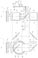
以下、1またはそれ以上の実施形態に係る投射型表示装置及び投射型表示装置の制御方法について、添付図面を参照して説明する。図1において、1またはそれ以上の実施形態に係る投射型表示装置100は、白色の照明光WiLを射出する光源部1を備える。光源部1は、図2に示すように構成される。図2において、B(B1及びB2)及びYはそれぞれ青色光及び黄色光を示す。
図2において、光源部1は、複数の青色レーザ素子11eよりなる光源11及び蛍光体ホイール120を有する。図2における(a)は光源部1の正面図であり、(b)は光源部1の側面図である。光源11より射出された青色光は集光レンズ12によって集光されて、分割ミラー13に入射する。分割ミラー13は、入射した青色光の一部(B1)を透過させ、残りの一部(B2)を反射させる。分割ミラー13で反射した青色光(B2)は、ミラー15及び19で反射し、集光レンズ18によって集光されてミラー17で反射する。
ミラー17で反射した青色光(B2)は、ダイクロイックミラー16で反射する。ダイクロイックミラー16は、青色光を反射し、黄色光を透過させる特性を有する。
分割ミラー13を透過した青色光(B1)は、ダイクロイックミラー16で反射し、集光レンズ110及び111で集光されて、蛍光体ホイール120へと向かう。蛍光体ホイール120は、鏡面状の円盤121を、回転軸123を中心としてモータ124で回転させるように構成されている。円盤121の外周端部の近傍には、蛍光体122が塗布されている。集光レンズ110及び111で集光された青色光は蛍光体122に入射されて蛍光体122を励起し、赤色成分と緑色成分とを含む黄色光を発光する。
蛍光体122より射出される黄色光は、集光レンズ111及び110を介してダイクロイックミラー16に入射する。ダイクロイックミラー16は、黄色光を透過させる。上記のようにダイクロイックミラー16で反射した青色光(B2)と、ダイクロイックミラー16を透過した黄色光とは、白色の照明光WiLとして光源部1より射出する。
図1に戻り、光源部1より射出された照明光WiLは、ミラー2で反射してフライアイレンズ3a及び3bに入射する。ミラー2から後述する赤色用(R用)、緑色用(G用)、青色用(B用)光変調素子10R、10G、10Bの手前までの各光学要素は照明光学系を構成する。R用、G用、B用光変調素子10R、10G、10BをそれぞれR光変調素子10R、G光変調素子10G、B光変調素子10Bと称することとする。R光変調素子10R、G光変調素子10G、B光変調素子10Bを光変調素子10と総称することがある。
R光変調素子10R、G光変調素子10G、B光変調素子10Bは、反射型液晶表示素子である。即ち、R光変調素子10R、G光変調素子10G、B光変調素子10Bは、それぞれ、赤色用反射型液晶表示素子、緑色用反射型液晶表示素子、青色用反射型液晶表示素子である。R光変調素子10R、G光変調素子10G、B光変調素子10Bは、一般的にLCOS(Liquid Crystal On Silicon)素子と称される液晶表示素子であってもよい。
フライアイレンズ3a及び3bは、R光変調素子10R、G光変調素子10G、B光変調素子10Bに照射される照明光の照明分布を均一化する。フライアイレンズ3bより射出された照明光WiLは、偏光変換素子4に入射される。偏光変換素子4は、照明光WiLに含まれるs偏光(第1の偏光)及びp偏光(第2の偏光)をいずれか一方の偏光に揃える。一例として、偏光変換素子4は、偏光ビームスプリッタによってs偏光を透過させ、偏光ビームスプリッタを反射したp偏光を1/2波長板によってs偏光に変換して射出する。
偏光変換素子4より射出されたs偏光とされた照明光WiLは、集光レンズ5によって集光されて、クロスダイクロイックミラー6に入射する。クロスダイクロイックミラー6は、s偏光の照明光WiLを黄色照明光YiLと青色照明光BiLとに分離する。
クロスダイクロイックミラー6で分離された黄色照明光YiLはミラー71に入射して反射し、ダイクロイックミラー72に入射する。ダイクロイックミラー72は、黄色照明光YiLに含まれる赤色照明光RiLを透過させ、黄色照明光YiLに含まれる緑色照明光GiLを反射させる。赤色照明光RiLは集光レンズ73で集光されて、反射型偏光板74に入射する。ここでは、反射型偏光板74は、s偏光を透過させ、p偏光を反射させる。反射型偏光板74及び後述する反射型偏光板84及び94は、ワイヤグリッドで構成することができる。
R光変調素子10Rは、反射型偏光板74を介して入射するs偏光の赤色照明光RiLを映像データにおける赤色データ(Rデータ)に応じて変調した赤色変調光Rmを生成して反射させる。赤色変調光Rmはp偏光であり、赤色変調光Rmは反射型偏光板74で反射して色合成プリズム21に入射する。
ダイクロイックミラー72で反射した緑色照明光GiLは集光レンズ83で集光されて、反射型偏光板84に入射する。ここでは、反射型偏光板84は、s偏光を透過させ、p偏光を反射させる。G光変調素子10Gは、反射型偏光板84を介して入射するs偏光の緑色照明光GiLを映像データにおける緑色データ(Gデータ)に応じて変調した緑色変調光Gmを生成して反射させる。緑色変調光Gmはp偏光であり、緑色変調光Gmは反射型偏光板84で反射して色合成プリズム21に入射する。
クロスダイクロイックミラー6で分離された青色照明光BiLはミラー91に入射して反射し、集光レンズ93に入射する。青色照明光BiLは集光レンズ93で集光されて、反射型偏光板94に入射する。ここでは、反射型偏光板94は、s偏光を透過させ、p偏光を反射させる。
B光変調素子10Bは、反射型偏光板94を介して入射するs偏光の青色照明光BiLを映像データにおける青色データ(Bデータ)に応じて変調した青色変調光Bmを生成して反射させる。青色変調光Bmはp偏光であり、青色変調光Bmは反射型偏光板94で反射して色合成プリズム21に入射する。
色合成プリズム21は、赤色変調光Rm、緑色変調光Gm、青色変調光Bmを合成してフルカラー画像を生成する。投射レンズ22は、フルカラー画像を図示していないスクリーンに投射する。
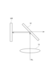
図1に示す構成例においては、s偏光を透過させ、p偏光を反射させる反射型偏光板74を用いているが、図3に示すように、反射型偏光板74の代わりに、s偏光を反射させ、p偏光を透過させる反射型偏光板74’を用いてもよい。反射型偏光板84及び94も同様であり、s偏光を透過させ、p偏光を反射させる反射型偏光板84及び94の代わりに、s偏光を反射させ、p偏光を透過させる反射型偏光板を用いてもよい。
以上説明した投射型表示装置100は投射型表示装置の一構成例であって、光源部1の構成は図2に示す構成に限定されないし、照明光学系の構成は図1に示す構成に限定されない。光源部1は、光源として水銀ランプ等の白色ランプを備えて構成されていてもよい。投射型表示装置100は、反射型液晶表示素子であるR光変調素子10R、G光変調素子10G、B光変調素子10Bを備えて、映像データ(R、G、Bデータ)に応じて赤色照明光RiL、緑色照明光GiL、青色照明光BiLを変調して投射画像を生成する構成であればよい。
投射型表示装置100において、光変調素子10に入射するs偏光のうち、光変調素子10で変調されずに反射したs偏光は、反射型偏光板74、84、94を透過して反射型偏光板74、84、94よりも光源部1側へと戻る。光変調素子10で変調されずに反射したs偏光は、照明光学系内まで戻って照明光学系内の集光レンズ73、83、93等の光学素子で反射して光変調素子10に再入射することがある。光変調素子10で変調されずに反射したs偏光は、光源部1まで戻って反射して光変調素子10に再入射することがある。
スクリーンに表示しようとする画像が黒で、Rデータ、Gデータ、Bデータの画素値が0であれば、光変調素子10に入射するs偏光は光変調素子10で変調されないから、大方のs偏光は光源部1側に戻る。スクリーンに表示しようとする画像がグレーであれば、光変調素子10に入射するs偏光のうちの一部が光変調素子10で変調されて投射レンズ22へと向かい、残りの一部は光変調素子10で変調されず光源部1側に戻る。スクリーンに表示しようとする画像が白で、Rデータ、Gデータ、Bデータの画素値が最大値であれば、光変調素子10に入射する大方のs偏光は光変調素子10で変調されて投射レンズ22へと向かう。
このように、光変調素子10に入射するs偏光のうち、どの程度のs偏光が反射型偏光板74、84、94を透過して反射型偏光板74、84、94よりも光源部1側へと戻るかは、スクリーンに表示しようとする画像によって変化する。また、反射型偏光板74、84、94よりも光源部1側に位置する光学素子または光源部1で反射して、反射型偏光板74、84、94を介して光変調素子10に再入射する再入射照明光の強度は、スクリーンに表示しようとする画像によって変化する。
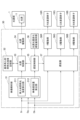
投射型表示装置100は、図1では図示を省略している図4に示す素子・光源駆動部30を備える。図4に示すように、素子・光源駆動部30は、映像解析部31、基準再入射照明光強度記憶部32、光源制御部33、光源駆動部34、遅延制御部35、光源光量変化遅延量保持部36、遅延器37、赤色駆動部(R駆動部)38R、緑色駆動部(G駆動部)38G、青色駆動部(B駆動部)38Bを備える。映像解析部31は、再入射照明光強度算出部311及び映像遅延量算出部312を有する。
図4において、映像解析部31には、映像データを構成するRデータDr、GデータDg、BデータDbが入力される。再入射照明光強度算出部311は、対象のフレームの映像を解析することによって、光変調素子10に入射するs偏光のうち、光変調素子10で変調されずに反射して光源部1側へと戻り、照明光学系内の光学素子または光源部1で反射して光変調素子10に再入射する再入射照明光の強度を算出する。映像を解析する対象のフレームとは、映像データを構成する各フレームでもよいし、2またはそれ以上のフレームごとの1フレームでもよい。
再入射照明光強度算出部311は、映像データにおける対象のフレームを構成する全画素の画素値に基づいて、再入射照明光の強度を算出し、対象のフレームにおける再入射照明光の強度を合算した合算値を算出する。再入射照明光強度算出部311は、RデータDrにおける各画素の画素値、GデータDgにおける各画素の画素値、BデータDbにおける各画素の画素値に基づいて各フレームの各画素の輝度値を求め、再入射照明光の強度及び合算値を算出する。
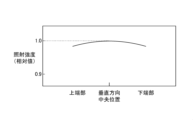
光変調素子10で変調されずに反射したs偏光が照明光学系内まで戻って照明光学系内の光学素子で反射して光変調素子10に再入射する強度と、光源部1まで戻って反射して光変調素子10に再入射する強度との比率は、予め実験によって求めることができる。光変調素子10に照射される照明光の照射強度は、光変調素子10の面内で均一ではなく、図5A及び図5Bに示すように、水平方向の左右端部及び垂直方向の上下端部ほど低い。
光変調素子10で変調されずに反射したs偏光が光源部1まで戻って反射して光変調素子10に再入射する場合は、図5A及び図5Bに示す照射強度の特性の影響を受けない。これは、光源部1まで戻る再入射により照射強度の特性が相殺されるからである。光変調素子10で変調されずに反射したs偏光が照明光学系内の光学素子で反射して光変調素子10に再入射する場合は、図5A及び図5Bに示す照射強度の特性の影響を受ける。
そこで、再入射照明光強度算出部311は、光変調素子10に入射するs偏光における水平方向及び垂直方向の各位置における照射強度を考慮して、照明光学系内の光学素子で反射して光変調素子10に再入射するs偏光の強度を算出することが好ましい。
基準再入射照明光強度記憶部32には、スクリーン(光変調素子10)に基準フレーム画像を表示したときの、各画素の再入射照明光の強度を全ての画素で合算した基準合算値が記憶されている。基準フレーム画像とは、例えば、対象のフレームの全体で、フレームを構成するRデータDr、GデータDg、及びBデータDbにおける各画素が最小階調から最大階調までの各階調で均一の画素値を有する投射画像である。
光源制御部33は、再入射照明光強度算出部311が算出した再入射照明光の合算値と、選択した基準フレーム画像の基準合算値とを比較して、光源部1における光源11による発光量を制御する。具体的には、光源制御部33は、光源11における青色レーザ素子11eの発光量を制御するための駆動電流値を決定する。光源駆動部34は、光源制御部33が決定した駆動電流値の電流を各青色レーザ素子11eに流すよう光源11を駆動する。
光源制御部33は、次のようにして基準フレーム画像を選択すればよい。第1の例として、光源制御部33は、映像データにおける対象のフレームの中心画素を代表画素とし、代表画素の画素値と同じ画素値を有する基準フレーム画像を選択する。光源制御部33は、再入射照明光強度算出部311より供給される再入射照明光の合算値が基準フレーム画像の基準合算値より大きければ駆動電流値を下げ、再入射照明光の合算値が基準フレーム画像の基準合算値より小さければ駆動電流値を上げる。第1の例においては、映像データの各フレームの中心の明るさを正確に補正することができる。
第2の例として、光源制御部33は、映像データにおける対象のフレームを複数の区画に分割し、各区画の中心画素を代表画素とし、複数の代表画素の画素値の平均値と同じ画素値を有する基準フレーム画像を選択する。光源制御部33は、再入射照明光強度算出部311より供給される再入射照明光の合算値が基準フレーム画像の基準合算値より大きければ駆動電流値を下げ、再入射照明光の合算値が基準フレーム画像の基準合算値より小さければ駆動電流値を上げる。第2の例においては、各フレームの全体において適切な明るさに補正することができる。
光源制御部33が基準フレーム画像を選択する方法は、第1の例または第2の例に限定されない。光源制御部33は、対象のフレームの中央部に所定の大きさの注目領域を設定し、注目領域内の全ての画素の画素値の平均値と同じ画素値を有する基準フレーム画像を選択してもよい。このように、光源制御部33は、基準フレーム画像を選択する複数の方法からいずれかの方法を選択すればよい。
このように、素子・光源駆動部30においては、光源制御部33によって光源11の発光量を制御することによって、光変調素子10への照明光の再入射を起因とする表示輝度の変化を補正する。この補正方法によれば、色データ(RデータDr、GデータDg、及びBデータDb)にゲインを乗じる方法とは異なり、画素値が最大値となって白飛びを起こすことはない。よって、投射型表示装置100は、素子・光源駆動部30を備えることにより、表示輝度の変化を適切に補正することが可能である。
ところで、R光変調素子10R、G光変調素子10G、B光変調素子10Bに表示するフレームが切り替わる際に、光源駆動部34が光源11の発光量を切り替えるよう駆動して発光量が実際に切り替わるタイミングと、R光変調素子10R、G光変調素子10G、B光変調素子10Bに映像が実際に表示されるタイミングとが一致していることが望ましい。
光源駆動部34が、フレームの切り替わりに対応して、直前のフレームの駆動電流値から現フレームの駆動電流値へと切り替えた時点から、青色レーザ素子11eに流れる駆動電流値が実際に変化して発光量が変化する時点との間には、所定時間の遅延時間が存在する。この遅延時間は固定の時間である。光変調素子10においては、液晶の特性によって印加される電圧が変化したときの応答特性が異なる。光変調素子10に表示するフレームが切り替わって、スクリーンに表示される画像の輝度が変化するまで数ms程度の応答時間がかかる場合がある。さらには、直前のフレームから現フレームへと輝度値がどのように変化するかによって応答時間が変化する。典型的には、直前のフレームと現フレームとの輝度値の差が大きいほど、応答時間が長い。
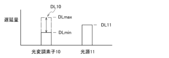
映像データのフレームが直前のフレームから現フレームに切り替わった時点から現フレームの映像が光変調素子10に表示されるまでの光変調素子10の応答時間に起因する遅延時間を図6Aに示す第1の遅延時間DL10とする。図6Aに示すように、第1の遅延時間DL10は、最小遅延時間DLminから最大遅延時間DLmaxまでの範囲で変化する。映像遅延量算出部312は、直前のフレームと現フレームとを比較することによって第1の遅延時間DL10を算出する。
光変調素子10に表示するフレームが直前のフレームから現フレームに切り替わった時点から光源11が現フレームに対応する発光量の光を射出するまでの固定の遅延時間を図6Aに示す第2の遅延時間DL11とする。第1の遅延時間DL10と第2の遅延時間DL11とは通常同じではない。
光源光量変化遅延量保持部36には、予め計測された第2の遅延時間DL11が保持されている。光源光量変化遅延量保持部36は例えば不揮発性メモリで構成することができる。遅延制御部35は、映像遅延量算出部312で算出された第1の遅延時間DL10と光源光量変化遅延量保持部36に保持されている第2の遅延時間DL11とを、フレームが切り替わるたびに比較する。RデータDr、GデータDg、及びBデータDbは、遅延器37を介してそれぞれR駆動部38R、G駆動部38G、及びB駆動部38Bに供給される。
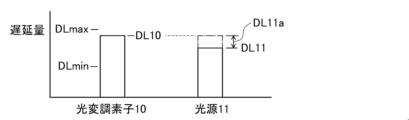
図6Bに示すように、遅延制御部35は、第1の遅延時間DL10が第2の遅延時間DL11よりも長ければ、遅延器37における遅延量を0とし、光源制御部33が現フレームに対応する発光量の光を射出するよう光源11を駆動する光源駆動部34を制御するタイミングを時間DL11aだけ遅延させる。遅延制御部35は、現フレームの映像が光変調素子10に表示されるタイミングと、光源11が現フレームに対応する発光量の光を射出するタイミングとを近付けるように、光源駆動部34を制御するタイミングを遅延させる。図6Bに示すように、遅延制御部35は、現フレームの映像が光変調素子10に表示されるタイミングと、光源11が現フレームに対応する発光量の光を射出するタイミングとを一致させるよう、光源駆動部34を制御するタイミングを遅らせることが好ましい。
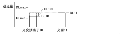
図6Cに示すように、遅延制御部35は、第2の遅延時間DL11が第1の遅延時間DL10よりも長ければ、遅延器37における遅延量を0を超える時間DL10aとするよう制御して、遅延器37によってRデータDr、GデータDg、及びBデータDbを遅延させる。遅延制御部35は、現フレームの映像が光変調素子10に表示されるタイミングと、光源11が現フレームに対応する発光量の光を射出するタイミングとを近付けるように、遅延器37による遅延量を制御する。図6Cに示すように、遅延制御部35は、現フレームの映像が光変調素子10に表示されるタイミングと、光源11が現フレームに対応する発光量の光を射出するタイミングとを一致させるよう、遅延器37による遅延量を制御することが好ましい。
このように、遅延制御部35は、好ましくは、現フレームの映像が光変調素子10に表示されるタイミングと、光源11が現フレームに対応する発光量の光を射出するタイミングとを一致させるよう、遅延器37による遅延量を制御し、光源制御部33によって光源駆動部34を制御するタイミングを制御する。すると、図6Dに示すように、スクリーンには、投射画像が、第2の遅延時間DL11に相当する最小遅延時間DLsminと、第1の遅延時間DL10の最大遅延時間DLmaxに相当する最大遅延時間DLsmaxとの間で変動する遅延時間だけ遅延しながら表示される。図6Dに示す遅延制御部35による光源制御部33及び遅延器37の制御方法によれば、スクリーンに表示される投射画像のフレームの長さがわずかに変動する。
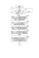
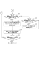
図7A及び図7Bに示すフローチャートを用いて、投射型表示装置100の動作であり、投射型表示装置100(素子・光源駆動部30)が実行する投射型表示装置の制御方法をさらに説明する。図7A及び図7Bでは、各フレームを対象のフレームとしている。図7Aにおいて、投射型表示装置100に映像データが入力されて処理が開始されると、映像解析部31は、ステップS11にて、映像データのフレームが切り替わったか否かを判定する。映像データのフレームが切り替わっていなければ(NO)、映像解析部31はステップS11の処理を繰り返す。
ステップS11にて映像データのフレームが切り替わっていれば(YES)、再入射照明光強度算出部311は、ステップS21にて、現フレームの全画素の画素値に基づき再入射照明光の強度を合算した合算値を算出する。光源制御部33は、ステップS22にて、現フレームに対応する基準フレーム画像の基準合算値を選択する。光源制御部33は、ステップS23にて、ステップS21で算出した合算値とステップS22で選択した基準合算値とを比較して、光源11の発光量を決定する。
映像遅延量算出部312は、ステップS31にて、現フレームの映像が光変調素子10に表示されるまでの第1の遅延時間DL10を算出する。遅延制御部35は、ステップS32にて、第1の遅延時間DL10と、光源11が現フレームに対応する発光量の光を射出するまでの第2の遅延時間DL11とを比較する。図7Bにおいて、遅延制御部35は、ステップS33にて、第1の遅延時間DL10が第2の遅延時間DL11より長いか否かを判定する。第1の遅延時間DL10が第2の遅延時間DL11より長ければ(YES)、遅延制御部35は、ステップS34にて、現フレームに対応する発光量の光を射出するタイミングを遅延させる遅延量を決定して、処理をステップS12に移行させる。
ステップS33にて第1の遅延時間DL10が第2の遅延時間DL11より長くなければ(NO)、遅延制御部35は、ステップS35にて、第2の遅延時間DL11が第1の遅延時間DL10より長いか否かを判定する。第2の遅延時間DL11が第1の遅延時間DL10より長ければ(YES)、遅延制御部35は、ステップS36にて、映像データを遅延させる遅延量を決定して、処理をステップS12に移行させる。第2の遅延時間DL11が第1の遅延時間DL10より長くなければ(NO)、遅延制御部35は処理をステップS12に移行させる。
素子・光源駆動部30は、ステップS12にて、決定した発光量及び遅延量に基づいてスクリーンに画像を投射するよう、光源部1及び光変調素子10を駆動して、処理をステップS13に移行させる。素子・光源駆動部30は、ステップS13にて、画像をスクリーンに投射する動作を終了するか否かを判定する。画像をスクリーンに投射する動作を終了しなければ(NO)、素子・光源駆動部30は、図7Aに示すステップS11以降の処理を繰り返す。画像をスクリーンに投射する動作を終了すれば(YES)、素子・光源駆動部30は処理を終了させる。
図7A及び図7Bにおいては、ステップS21~S23の処理の後に、ステップS31~S36の処理を設けているが、順番は逆であってもよく、ステップS21~S23の処理とステップS31~S36の処理とが並列的に実行されてもよい。
図6B及び図6Cにおいては、遅延制御部35は、第1の遅延時間DL10と第2の遅延時間DL11との比較結果に基づいて、遅延器37による遅延量と、光源制御部33が光源駆動部34を制御するタイミングとの一方を制御している。これによって、現フレームの映像が光変調素子10に表示されるタイミングと、光源11が現フレームに対応する発光量の光を射出するタイミングとを一致させている。遅延器37による遅延量と、光源制御部33が光源駆動部34を制御するタイミングとの双方を制御して、現フレームの映像が光変調素子10に表示されるタイミングと、光源11が現フレームに対応する発光量の光を射出するタイミングとを一致させてもよい。
遅延制御部35は、遅延器37による遅延量と、光源制御部33が光源駆動部34を制御するタイミングとの少なくとも一方を制御して、現フレームの映像が光変調素子10に表示されるタイミングと、光源11が現フレームに対応する発光量の光を射出するタイミングとを一致させればよい。
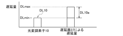
さらに、素子・光源駆動部30の好ましい構成例を説明する。遅延制御部35は、次のように、遅延器37による遅延量と、光源制御部33が光源駆動部34を制御するタイミングとを制御することが好ましい。図8Aは、第1の遅延時間DL10が最小遅延時間DLminである場合を示している。遅延制御部35は、映像データを最大遅延時間DLmaxと、そのときの第1の遅延時間DL10である最小遅延時間DLminとの差分の時間DL10aだけ遅延させるよう遅延器37を制御する。このときの遅延時間DL10aは最大遅延時間である。
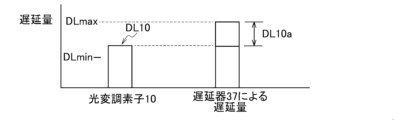
図8Bは、第1の遅延時間DL10が最小遅延時間DLminと最大遅延時間DLmaxとの中間の遅延時間である場合を示している。遅延制御部35は、映像データを最大遅延時間DLmaxと、そのときの第1の遅延時間DL10である中間の遅延時間との差分の時間DL10aだけ遅延させるよう遅延器37を制御する。このときの遅延時間DL10aは図8Aにおける遅延時間DL10aの最大遅延時間より短い時間である。
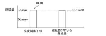
図8Cは、第1の遅延時間DL10が最大遅延時間DLmaxである場合を示している。最大遅延時間DLmaxと、そのときの第1の遅延時間DL10である最大遅延時間DLmaxとの差分の時間DL10aは0である。よって、遅延制御部35は、遅延器37による遅延量を0とする。
このように、遅延制御部35は、遅延器37によって映像データを最大遅延時間DLmaxと各フレームにおける第1の遅延時間DL10の差分の時間だけ遅延させる。映像データの遅延量は0である場合がある。
図8Dに示すように、遅延制御部35は、最大遅延時間DLmaxと第2の遅延時間DL11との差分の時間DL11aだけ、現フレームに対応する発光量の光を射出するよう光源11を駆動する光源駆動部34を制御するタイミングを遅延させるよう光源制御部33を制御する。すると、図8Dに示すように、スクリーンには、第1の遅延時間DL10が最小遅延時間DLminと最大遅延時間DLmaxとの間のどのような遅延時間であっても、投射画像が、最大遅延時間DLmaxに相当する固定の遅延時間DLfixだけ遅延して表示される。
図8A~図8Dに示す素子・光源駆動部30の好ましい構成例における遅延制御部35による光源制御部33及び遅延器37の制御方法によれば、スクリーンに表示される投射画像のフレームの長さを一定に保つことができる。よって、素子・光源駆動部30の好ましい構成例によれば、スクリーンに表示される投射画像の品位を向上させることができる。
本発明は以上説明した1またはそれ以上の実施形態に限定されるものではなく、本発明の要旨を逸脱しない範囲において種々変更可能である。
本願は、2023年9月22日に日本国特許庁に出願された特願2023-158432号に基づく優先権を主張するものであり、その全ての開示内容は引用によりここに援用される。
Claims (4)
- 反射型液晶表示素子に表示する映像データにおける各フレームのうちの映像を解析する対象のフレームを構成する画素ごとに、第1及び第2の偏光を含む照明光における偏光板を介して前記反射型液晶表示素子に入射する第1の偏光のうち、前記反射型液晶表示素子で変調されずに反射して前記偏光板よりも光源部側へと戻り、前記偏光板よりも前記光源部側に位置する光学素子または前記光源部で反射して前記偏光板を介して前記反射型液晶表示素子に再入射する前記第1の偏光である再入射照明光の強度を算出し、前記対象のフレームを構成する全ての画素に対して算出された前記再入射照明光の強度を合算した合算値を算出する再入射照明光強度算出部と、
前記反射型液晶表示素子に最小階調から最大階調までの基準フレーム画像を表示したときの各画素の前記再入射照明光の強度を全ての画素で合算した基準合算値を記憶する基準再入射照明光強度記憶部と、
前記対象のフレームに基づいていずれかの前記基準フレーム画像の基準合算値を選択し、前記再入射照明光強度算出部によって算出された前記合算値と選択された前記基準合算値とを比較して、前記光源部が備える光源による発光量を制御する光源制御部と、
を備える投射型表示装置。 - 前記映像データにおける前記反射型液晶表示素子に表示するフレームが直前のフレームから現フレームに切り替わった時点から前記現フレームの映像が前記反射型液晶表示素子に表示されるまでの第1の遅延時間を算出する映像遅延量算出部と、
前記反射型液晶表示素子に供給する前記映像データを遅延させる遅延器と、
前記第1の遅延時間と、前記映像データにおける前記反射型液晶表示素子に表示するフレームが直前のフレームから現フレームに切り替わった時点から前記光源が前記現フレームに対応する発光量の光を射出するまでの第2の遅延時間とを比較した比較結果に基づいて、前記現フレームの映像が前記反射型液晶表示素子に表示されるタイミングと、前記光源が前記現フレームに対応する発光量の光を射出するタイミングとを一致させるよう、前記遅延器によって前記映像データを遅延させる遅延量と、前記光源制御部が前記現フレームに対応する発光量の光を射出するよう前記光源を駆動する光源駆動部を制御するタイミングとの少なくとも一方を制御する遅延制御部と、
をさらに備える請求項1に記載の投射型表示装置。 - 前記映像データにおける前記反射型液晶表示素子に表示するフレームが直前のフレームから現フレームに切り替わった時点から前記現フレームの映像が前記反射型液晶表示素子に表示されるまでの最小遅延時間から最大遅延時間までの範囲で変化する第1の遅延時間を算出する映像遅延量算出部と、
前記反射型液晶表示素子に供給する前記映像データを遅延させる遅延器と、
前記映像データを前記最大遅延時間と前記第1の遅延時間の差分の時間だけ遅延させるよう前記遅延器を制御し、かつ、前記最大遅延時間と、前記映像データにおける前記反射型液晶表示素子に表示するフレームが直前のフレームから現フレームに切り替わった時点から前記光源が前記現フレームに対応する発光量の光を射出するまでの第2の遅延時間との差分の時間だけ、前記現フレームに対応する発光量の光を射出するよう前記光源を駆動する光源駆動部を制御するタイミングを遅延させるよう前記光源制御部を制御する遅延制御部と、
をさらに備える請求項1に記載の投射型表示装置。 - 反射型液晶表示素子に表示する映像データにおける各フレームのうちの映像を解析する対象のフレームを構成する画素ごとに、第1及び第2の偏光を含む照明光における偏光板を介して前記反射型液晶表示素子に入射する第1の偏光のうち、前記反射型液晶表示素子で変調されずに反射して前記偏光板よりも光源部側へと戻り、前記偏光板よりも前記光源部側に位置する光学素子または前記光源部で反射して前記偏光板を介して前記反射型液晶表示素子に再入射する前記第1の偏光である再入射照明光の強度を算出し、前記対象のフレームを構成する全ての画素に対して算出された前記再入射照明光の強度を合算した合算値を算出し、
基準再入射照明光強度記憶部に記憶されている、前記反射型液晶表示素子に最小階調から最大階調までの基準フレーム画像を表示したときの各画素の前記再入射照明光の強度を全ての画素で合算した基準合算値のうちから、前記対象のフレームに基づいていずれかの前記基準フレーム画像の基準合算値を選択し、
算出された前記合算値と選択された前記基準合算値とを比較して、前記光源部が備える光源による発光量を制御する
投射型表示装置の制御方法。
Applications Claiming Priority (2)
| Application Number | Priority Date | Filing Date | Title |
|---|---|---|---|
| JP2023-158432 | 2023-09-22 | ||
| JP2023158432A JP2025049920A (ja) | 2023-09-22 | 2023-09-22 | 投射型表示装置及び投射型表示装置の制御方法 |
Publications (1)
| Publication Number | Publication Date |
|---|---|
| WO2025062863A1 true WO2025062863A1 (ja) | 2025-03-27 |
Family
ID=95072647
Family Applications (1)
| Application Number | Title | Priority Date | Filing Date |
|---|---|---|---|
| PCT/JP2024/028171 Pending WO2025062863A1 (ja) | 2023-09-22 | 2024-08-07 | 投射型表示装置及び投射型表示装置の制御方法 |
Country Status (2)
| Country | Link |
|---|---|
| JP (1) | JP2025049920A (ja) |
| WO (1) | WO2025062863A1 (ja) |
Citations (5)
| Publication number | Priority date | Publication date | Assignee | Title |
|---|---|---|---|---|
| US20080246706A1 (en) * | 2007-04-03 | 2008-10-09 | Texas Instruments Incorporated | Pulse width modulation algorithm |
| US20120105809A1 (en) * | 2010-10-27 | 2012-05-03 | Hon Hai Precision Industry Co., Ltd. | Projection device with brightness adjustment function and method thereof |
| JP2013080149A (ja) * | 2011-10-05 | 2013-05-02 | Seiko Epson Corp | プロジェクター |
| JP2017069808A (ja) * | 2015-09-30 | 2017-04-06 | 株式会社Jvcケンウッド | 検出方法、検出装置および投射装置 |
| JP2021032970A (ja) * | 2019-08-21 | 2021-03-01 | 株式会社Jvcケンウッド | 光量調整装置、投射装置、及び光量調整方法 |
-
2023
- 2023-09-22 JP JP2023158432A patent/JP2025049920A/ja active Pending
-
2024
- 2024-08-07 WO PCT/JP2024/028171 patent/WO2025062863A1/ja active Pending
Patent Citations (5)
| Publication number | Priority date | Publication date | Assignee | Title |
|---|---|---|---|---|
| US20080246706A1 (en) * | 2007-04-03 | 2008-10-09 | Texas Instruments Incorporated | Pulse width modulation algorithm |
| US20120105809A1 (en) * | 2010-10-27 | 2012-05-03 | Hon Hai Precision Industry Co., Ltd. | Projection device with brightness adjustment function and method thereof |
| JP2013080149A (ja) * | 2011-10-05 | 2013-05-02 | Seiko Epson Corp | プロジェクター |
| JP2017069808A (ja) * | 2015-09-30 | 2017-04-06 | 株式会社Jvcケンウッド | 検出方法、検出装置および投射装置 |
| JP2021032970A (ja) * | 2019-08-21 | 2021-03-01 | 株式会社Jvcケンウッド | 光量調整装置、投射装置、及び光量調整方法 |
Also Published As
| Publication number | Publication date |
|---|---|
| JP2025049920A (ja) | 2025-04-04 |
Similar Documents
| Publication | Publication Date | Title |
|---|---|---|
| US6905216B2 (en) | Method of and device for generating an image having a desired brightness | |
| JP6569440B2 (ja) | 検出方法、検出装置および投射装置 | |
| US10291887B2 (en) | Projection system and control method therefor | |
| JP4819255B2 (ja) | 表示装置 | |
| US6885428B2 (en) | Light source device and projection television | |
| CN106990656B (zh) | 投影机以及控制方法 | |
| JP6398185B2 (ja) | プロジェクター、及び、プロジェクターの制御方法 | |
| US8711290B2 (en) | Projection-type video-image display apparatus | |
| US8733946B2 (en) | Image display device | |
| US20050168699A1 (en) | Projector | |
| JP2014142524A (ja) | 光源装置および投写型映像表示装置 | |
| JP4552985B2 (ja) | 画像表示装置 | |
| US12425553B2 (en) | Projection display device and video correction method | |
| US8519924B2 (en) | Image display device and method of driving liquid crystal panel | |
| US8665252B2 (en) | Duty cycle calculation and implementation for solid state illuminators | |
| WO2025062863A1 (ja) | 投射型表示装置及び投射型表示装置の制御方法 | |
| CN113826044B (zh) | 光量调整装置、投射装置以及光量调整方法 | |
| US11016376B2 (en) | Projector and method for controlling projector | |
| US20060227147A1 (en) | Method and apparatus for an image presentation device with illumination control for black image processing | |
| JP2000347137A (ja) | プロジェクター装置 | |
| JP2004233813A (ja) | 色むら補正画像処理装置、方法及びプログラム、並びに投射型画像表示装置 | |
| JP2008089836A (ja) | プロジェクタ | |
| JP2005274732A (ja) | 投写型映像表示装置 | |
| US20250013138A1 (en) | Light source device, projector, control method for light source device, and program | |
| JP2011017792A (ja) | 投射型映像表示装置 |
Legal Events
| Date | Code | Title | Description |
|---|---|---|---|
| 121 | Ep: the epo has been informed by wipo that ep was designated in this application |
Ref document number: 24867944 Country of ref document: EP Kind code of ref document: A1 |