WO2025057798A1 - 基板処理システム及び可動式メンテナンス装置 - Google Patents
基板処理システム及び可動式メンテナンス装置 Download PDFInfo
- Publication number
- WO2025057798A1 WO2025057798A1 PCT/JP2024/031455 JP2024031455W WO2025057798A1 WO 2025057798 A1 WO2025057798 A1 WO 2025057798A1 JP 2024031455 W JP2024031455 W JP 2024031455W WO 2025057798 A1 WO2025057798 A1 WO 2025057798A1
- Authority
- WO
- WIPO (PCT)
- Prior art keywords
- chamber
- substrate processing
- vacuum transfer
- maintenance
- magnetically levitated
- Prior art date
- Legal status (The legal status is an assumption and is not a legal conclusion. Google has not performed a legal analysis and makes no representation as to the accuracy of the status listed.)
- Ceased
Links
Images



Classifications
-
- A—HUMAN NECESSITIES
- A46—BRUSHWARE
- A46B—BRUSHES
- A46B13/00—Brushes with driven brush bodies or carriers
- A46B13/02—Brushes with driven brush bodies or carriers power-driven carriers
-
- H—ELECTRICITY
- H10—SEMICONDUCTOR DEVICES; ELECTRIC SOLID-STATE DEVICES NOT OTHERWISE PROVIDED FOR
- H10P—GENERIC PROCESSES OR APPARATUS FOR THE MANUFACTURE OR TREATMENT OF DEVICES COVERED BY CLASS H10
- H10P72/00—Handling or holding of wafers, substrates or devices during manufacture or treatment thereof
- H10P72/30—Handling or holding of wafers, substrates or devices during manufacture or treatment thereof for conveying, e.g. between different workstations
- H10P72/32—Handling or holding of wafers, substrates or devices during manufacture or treatment thereof for conveying, e.g. between different workstations between different workstations
- H10P72/3204—Handling or holding of wafers, substrates or devices during manufacture or treatment thereof for conveying, e.g. between different workstations between different workstations using magnetic elements
-
- A—HUMAN NECESSITIES
- A46—BRUSHWARE
- A46B—BRUSHES
- A46B15/00—Other brushes; Brushes with additional arrangements
- A46B15/0002—Arrangements for enhancing monitoring or controlling the brushing process
- A46B15/0004—Arrangements for enhancing monitoring or controlling the brushing process with a controlling means
- A46B15/0006—Arrangements for enhancing monitoring or controlling the brushing process with a controlling means with a controlling brush technique device, e.g. stroke movement measuring device
-
- A—HUMAN NECESSITIES
- A46—BRUSHWARE
- A46B—BRUSHES
- A46B5/00—Brush bodies; Handles integral with brushware
- A46B5/0004—Additional brush head
-
- A—HUMAN NECESSITIES
- A46—BRUSHWARE
- A46B—BRUSHES
- A46B5/00—Brush bodies; Handles integral with brushware
- A46B5/06—Brush bodies; Handles integral with brushware in the form of tapes, chains, flexible shafts, springs, mats or the like
-
- B—PERFORMING OPERATIONS; TRANSPORTING
- B65—CONVEYING; PACKING; STORING; HANDLING THIN OR FILAMENTARY MATERIAL
- B65G—TRANSPORT OR STORAGE DEVICES, e.g. CONVEYORS FOR LOADING OR TIPPING, SHOP CONVEYOR SYSTEMS OR PNEUMATIC TUBE CONVEYORS
- B65G54/00—Non-mechanical conveyors not otherwise provided for
- B65G54/02—Non-mechanical conveyors not otherwise provided for electrostatic, electric, or magnetic
-
- H—ELECTRICITY
- H10—SEMICONDUCTOR DEVICES; ELECTRIC SOLID-STATE DEVICES NOT OTHERWISE PROVIDED FOR
- H10P—GENERIC PROCESSES OR APPARATUS FOR THE MANUFACTURE OR TREATMENT OF DEVICES COVERED BY CLASS H10
- H10P72/00—Handling or holding of wafers, substrates or devices during manufacture or treatment thereof
- H10P72/04—Apparatus for manufacture or treatment
- H10P72/0402—Apparatus for fluid treatment
- H10P72/0406—Apparatus for fluid treatment for cleaning followed by drying, rinsing, stripping, blasting or the like
-
- H—ELECTRICITY
- H10—SEMICONDUCTOR DEVICES; ELECTRIC SOLID-STATE DEVICES NOT OTHERWISE PROVIDED FOR
- H10P—GENERIC PROCESSES OR APPARATUS FOR THE MANUFACTURE OR TREATMENT OF DEVICES COVERED BY CLASS H10
- H10P72/00—Handling or holding of wafers, substrates or devices during manufacture or treatment thereof
- H10P72/04—Apparatus for manufacture or treatment
- H10P72/0441—Apparatus for sealing, encapsulating, glassing, decapsulating or the like
-
- H—ELECTRICITY
- H10—SEMICONDUCTOR DEVICES; ELECTRIC SOLID-STATE DEVICES NOT OTHERWISE PROVIDED FOR
- H10P—GENERIC PROCESSES OR APPARATUS FOR THE MANUFACTURE OR TREATMENT OF DEVICES COVERED BY CLASS H10
- H10P72/00—Handling or holding of wafers, substrates or devices during manufacture or treatment thereof
- H10P72/04—Apparatus for manufacture or treatment
- H10P72/0451—Apparatus for manufacturing or treating in a plurality of work-stations
- H10P72/0452—Apparatus for manufacturing or treating in a plurality of work-stations characterised by the layout of the process chambers
- H10P72/0454—Apparatus for manufacturing or treating in a plurality of work-stations characterised by the layout of the process chambers surrounding a central transfer chamber
-
- H—ELECTRICITY
- H10—SEMICONDUCTOR DEVICES; ELECTRIC SOLID-STATE DEVICES NOT OTHERWISE PROVIDED FOR
- H10P—GENERIC PROCESSES OR APPARATUS FOR THE MANUFACTURE OR TREATMENT OF DEVICES COVERED BY CLASS H10
- H10P72/00—Handling or holding of wafers, substrates or devices during manufacture or treatment thereof
- H10P72/04—Apparatus for manufacture or treatment
- H10P72/0451—Apparatus for manufacturing or treating in a plurality of work-stations
- H10P72/0464—Apparatus for manufacturing or treating in a plurality of work-stations characterised by the construction of the transfer chamber
-
- H—ELECTRICITY
- H10—SEMICONDUCTOR DEVICES; ELECTRIC SOLID-STATE DEVICES NOT OTHERWISE PROVIDED FOR
- H10P—GENERIC PROCESSES OR APPARATUS FOR THE MANUFACTURE OR TREATMENT OF DEVICES COVERED BY CLASS H10
- H10P72/00—Handling or holding of wafers, substrates or devices during manufacture or treatment thereof
- H10P72/04—Apparatus for manufacture or treatment
- H10P72/0451—Apparatus for manufacturing or treating in a plurality of work-stations
- H10P72/0466—Apparatus for manufacturing or treating in a plurality of work-stations characterised by the construction of the load-lock chamber
-
- H—ELECTRICITY
- H10—SEMICONDUCTOR DEVICES; ELECTRIC SOLID-STATE DEVICES NOT OTHERWISE PROVIDED FOR
- H10P—GENERIC PROCESSES OR APPARATUS FOR THE MANUFACTURE OR TREATMENT OF DEVICES COVERED BY CLASS H10
- H10P72/00—Handling or holding of wafers, substrates or devices during manufacture or treatment thereof
- H10P72/06—Apparatus for monitoring, sorting, marking, testing or measuring
- H10P72/0604—Process monitoring, e.g. flow or thickness monitoring
-
- H—ELECTRICITY
- H10—SEMICONDUCTOR DEVICES; ELECTRIC SOLID-STATE DEVICES NOT OTHERWISE PROVIDED FOR
- H10P—GENERIC PROCESSES OR APPARATUS FOR THE MANUFACTURE OR TREATMENT OF DEVICES COVERED BY CLASS H10
- H10P72/00—Handling or holding of wafers, substrates or devices during manufacture or treatment thereof
- H10P72/30—Handling or holding of wafers, substrates or devices during manufacture or treatment thereof for conveying, e.g. between different workstations
-
- H—ELECTRICITY
- H10—SEMICONDUCTOR DEVICES; ELECTRIC SOLID-STATE DEVICES NOT OTHERWISE PROVIDED FOR
- H10P—GENERIC PROCESSES OR APPARATUS FOR THE MANUFACTURE OR TREATMENT OF DEVICES COVERED BY CLASS H10
- H10P72/00—Handling or holding of wafers, substrates or devices during manufacture or treatment thereof
- H10P72/30—Handling or holding of wafers, substrates or devices during manufacture or treatment thereof for conveying, e.g. between different workstations
- H10P72/32—Handling or holding of wafers, substrates or devices during manufacture or treatment thereof for conveying, e.g. between different workstations between different workstations
- H10P72/3206—Handling or holding of wafers, substrates or devices during manufacture or treatment thereof for conveying, e.g. between different workstations between different workstations the substrate being handled substantially vertically
-
- H—ELECTRICITY
- H10—SEMICONDUCTOR DEVICES; ELECTRIC SOLID-STATE DEVICES NOT OTHERWISE PROVIDED FOR
- H10P—GENERIC PROCESSES OR APPARATUS FOR THE MANUFACTURE OR TREATMENT OF DEVICES COVERED BY CLASS H10
- H10P72/00—Handling or holding of wafers, substrates or devices during manufacture or treatment thereof
- H10P72/30—Handling or holding of wafers, substrates or devices during manufacture or treatment thereof for conveying, e.g. between different workstations
- H10P72/33—Handling or holding of wafers, substrates or devices during manufacture or treatment thereof for conveying, e.g. between different workstations into and out of processing chamber
- H10P72/3302—Mechanical parts of transfer devices
-
- A—HUMAN NECESSITIES
- A46—BRUSHWARE
- A46B—BRUSHES
- A46B2200/00—Brushes characterized by their functions, uses or applications
- A46B2200/30—Brushes for cleaning or polishing
- A46B2200/3073—Brush for cleaning specific unusual places not otherwise covered, e.g. gutters, golf clubs, tops of tin cans, corners
Definitions
- wafers In the manufacturing process of semiconductor devices, etc., various processes such as film formation and etching are performed on substrates such as semiconductor wafers (hereafter referred to as "wafers") in a vacuum atmosphere (reduced pressure atmosphere). These processes are performed in substrate processing equipment.
- wafers semiconductor wafers
- vacuum atmosphere reduced pressure atmosphere
- This substrate processing apparatus includes a substrate processing chamber in which the pressure inside is reduced and the above-mentioned processing is performed on the substrate, and a vacuum transfer chamber in which the pressure inside is also reduced and a substrate transfer unit is provided for transferring the substrate between the substrate processing chamber.
- the vacuum transfer module is configured to transfer the substrate under reduced pressure or vacuum environment, and includes a vacuum transfer chamber and a substrate transfer unit disposed within the vacuum transfer chamber.
- the substrate transport unit in the vacuum transport chamber may be of the magnetic levitation type.
- the magnetic levitation type substrate transport unit is configured to move on a planar motor with an array of coils, and has a support that supports the substrate.
- the substrate processing apparatus also includes a gate valve that opens and closes an opening that connects the substrate processing chamber to the vacuum transfer chamber.
- a magnetically levitated gate valve may be used as this gate valve.
- the magnetically levitated gate valve is configured to move on a planar motor, but unlike the substrate transfer unit, it has a valve body that closes the opening.
- the valve body of the magnetically levitated gate valve is also provided with a seal member that seals the opening when it is closed.
- Magnetic levitation units i.e., magnetic levitation mobile bodies, such as the magnetic levitation substrate transport unit described above
- replacement of sealing members are performed, for example, by an operator replacing the entire magnetic levitation unit with a previously used, i.e., unused, one.
- the vacuum transport chamber is opened to the atmosphere, it takes a long time to return the vacuum transport chamber to the state it was in before being opened to the atmosphere after replacement, which can reduce productivity.
- the technology disclosed herein performs maintenance on a substrate processing apparatus having a vacuum transfer chamber configured so that a magnetically levitated moving body can move inside, i.e., a magnetically levitated vacuum transfer chamber, without opening it to the atmosphere.
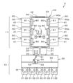
- Fig. 1 is a system configuration diagram showing an example of a substrate processing system according to the present embodiment.
- Fig. 2 is a plan view showing an outline of the configuration of a substrate processing apparatus included in the substrate processing system of Fig. 1.
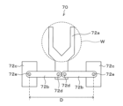
- Fig. 3 is a perspective view showing an outline of a substrate transport unit provided in the substrate processing apparatus of Fig. 2.
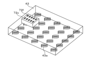
- Fig. 4 is a view for explaining the driving principle of the substrate transport unit.
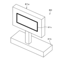
- Fig. 5 is a perspective view showing an outline of a gate valve provided in the substrate processing apparatus of Fig. 2.
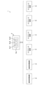
- the substrate processing system 1 in FIG. 1 includes multiple substrate processing devices 2, multiple maintenance devices 3, and a control device 4.
- each substrate processing apparatus 2 the substrate W is subjected to processes including, for example, a film formation process, a cleaning process, and other desired gas processes such as plasma processing.
- the substrate processing apparatus 2 has an atmospheric section 10 and a reduced pressure section 11 that are integrally connected via load lock modules 20 and 21.
- the atmospheric section 10 includes an atmospheric module that performs a desired process on the substrate W in an atmospheric pressure environment.
- the reduced pressure section 11 includes a reduced pressure module that performs a desired process on the substrate W in a reduced pressure environment.
- the load lock modules 20, 21 are provided to connect an atmospheric transfer module 30 (described later) in the atmospheric section 10 and a vacuum transfer module 40 (described later) in the reduced pressure section 11 via gate valves 22, 23, respectively.
- the load lock modules 20, 21 are configured to temporarily hold a substrate W.
- the load lock modules 20, 21 are also configured so that their interiors can be switched between an atmospheric pressure atmosphere and a reduced pressure atmosphere (vacuum atmosphere).
- the atmospheric section 10 has an atmospheric transfer module 30 equipped with a substrate transfer mechanism 50 described below, and a load port 32 on which a FOUP 31 capable of storing multiple substrates W is placed. Note that an orienter module (not shown) for adjusting the horizontal orientation of the substrate W and a storage module (not shown) for storing multiple substrates W may be provided adjacent to the atmospheric transfer module 30.
- the substrate transfer mechanism 50 for transferring the substrate W.
- the substrate transfer mechanism 50 has a transfer arm 51 which holds and moves the substrate W, a rotating table 52 which rotatably supports the transfer arm 51, and a rotating platform 53 on which the rotating table 52 is mounted.
- a guide rail 54 which extends in the longitudinal direction of the atmospheric transfer module 30.
- the rotating platform 53 is provided on the guide rail 54, and the substrate transfer mechanism 50 is configured to be movable along the guide rail 54.
- the decompression section 11 includes a vacuum transfer module 40 and a substrate processing module 60.
- the vacuum transfer module 40 is provided adjacent to the substrate processing module 60 and transfers the substrate W under a vacuum atmosphere.
- the substrate processing module 60 performs processes such as film formation on the substrate W under a vacuum atmosphere.
- Multiple substrate processing modules 60 are connected to one vacuum transfer module 40. Note that, although six substrate processing modules 60 are connected in the example shown in FIG. 2, this is not limited thereto, and fewer than six or more than six substrate processing modules 60 may be connected.
- the vacuum transfer module 40 includes a vacuum transfer chamber 40a
- the substrate processing module 60 includes a substrate processing chamber 60a.
- the vacuum transfer chamber 40a and the substrate processing chamber 60a are each configured to be able to maintain a reduced pressure atmosphere (vacuum atmosphere) inside.
- the vacuum transfer chamber 40a is connected to the load lock modules 20 and 21.
- the vacuum transfer module 40 transfers the substrate W transferred to the load lock module 20 to one of the substrate processing modules 60, where the substrate W is subjected to the desired substrate processing and then transferred to the load lock module 21.
- the vacuum transfer chamber 40 a has a first opening 41 and a second opening 42 .
- the vacuum transfer chamber 40a is connected to the substrate processing module 60, specifically, to the substrate processing chamber 60a, via a first opening 41.
- the first opening 41 connects the internal space of the vacuum transfer chamber 40a to the internal space of the substrate processing chamber 60a.
- the second opening 42 connects the internal space of the vacuum transfer chamber 40a to the outside of the substrate processing apparatus 2.
- the vacuum transfer chamber 40a is connected to a maintenance device 3, specifically, to a waiting chamber, via the second opening 42.
- the second opening 42 connects the internal space of the vacuum transfer chamber 40a to the internal space of the waiting chamber.
- the vacuum transfer chamber 40a is provided with a planar motor 43 as a first planar motor.
- the vacuum transfer chamber 40a is provided with a magnetic levitation type substrate transfer unit 70 and a magnetic levitation type gate valve 80 as magnetic levitation type moving bodies, and the vacuum transfer chamber 40a is also provided with a gate valve 90.
- the planar motor 43 has multiple coils 43a arranged in it.
- the coils 43a generate a magnetic field when a current is supplied to them.
- the current supply to the coils 43a is controlled by the control device 4.
- control device 4 can control the position, orientation, and levitation amount of the base 72c by controlling the current (specifically, the current value) of each coil 43a of the planar motor 43.
- the control device 4 can also move and rotate the transport unit 70 by controlling the energization of each coil 43a of the planar motor 43 so that the position of the base 72c is the desired position. In other words, the control device 4 can move the substrate W held by the end effector 72a of the transport unit 70 by controlling the energization of each coil 43a of the planar motor 43.
- the end effector 72a receives the substrate W held in the load lock module 20 and transfers it to the desired substrate processing module 60 (specifically, the substrate processing chamber 60a).
- the end effector 72a also holds the substrate W that has been subjected to the desired substrate processing in the substrate processing module 60 and transfers it to the load lock module 21.
- the gate valve 80 has a valve body 81a and a base 81b.
- the valve body 81a is a member that closes the first opening 41, and is formed to be larger than the first opening 41 and smaller than the second opening 42.
- the valve body 81a is provided with a seal member 81c that seals the portion of the first opening 41 that is closed by the valve body 81a.
- the seal member 81c is, for example, an O-ring.
- the valve body 81a is connected to a base 81b. Similar to the base 72c, a plurality of permanent magnets (not shown) are arranged on the base 81b.
- the base 81b moves on the planar motor 43 due to the magnetic field generated by the coil 43a of the planar motor 43.
- the control device 4 processes computer-executable instructions that cause the substrate processing device 2 and the maintenance device 3 to perform the various processes described in this disclosure.
- the control device 4 may be configured to control each element of the substrate processing device 2 and the maintenance device 3 to perform the various processes described herein. In one embodiment, a part or all of the control device 4 may be included in at least one of the substrate processing device 2 or the maintenance device 3.
- the control device 4 may include a processing unit 4a1, a storage unit 4a2, and a communication interface 4a3.
- the control device 4 is realized, for example, by a computer 4a.
- the processing unit 4a1 may be configured to perform various control operations by reading a program from the storage unit 4a2 and executing the read program.
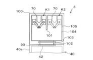
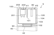
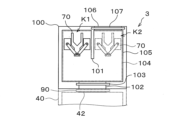
- the waiting chamber 100 is provided with an opening 102 that connects the waiting chamber 100 to the vacuum transfer chamber 40a via the second opening 42, and a gate valve 103 that opens and closes the opening 102.
- the control device 4 controls the energization of each coil of the planar motor 104, thereby allowing the moving body 72 to move.
- the lower wall surface 102a is made equal in height to the floor surface 105 of the waiting chamber 100, and a planar motor 104 may also be provided on the lower wall surface 102a forming the opening 102.
- the lower wall surface forming the second opening 42 of the vacuum transfer chamber 40a may be made equal in height to the floor surface of the vacuum transfer chamber 40a, and a planar motor 43 may also be provided on the lower wall surface forming the second opening 42.
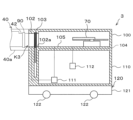
- the maintenance device 3 has an equipment room 110 as shown in FIG. 7.
- An exhaust mechanism 111 and a gas supply mechanism 112 are provided in the equipment room 110.
- the exhaust mechanism 111 and the gas supply mechanism 112 are controlled by the control device 4.
- a protrusion for alignment may be provided on either the side of the vacuum transfer chamber 40a connected to the maintenance device 3 or the side of the maintenance device 3 connected to the vacuum transfer chamber 40a, and a recess into which the protrusion fits may be provided on the other side.
- At least one of a seal member surrounding the second opening 42 on the side of the vacuum transfer chamber 40a connected to the maintenance device 3 and a seal member surrounding the opening 102 on the side of the maintenance device 3 connected to the vacuum transfer chamber 40a may be provided.
- This seal member or these seal members can increase the airtightness of the connection between the second opening 42 and the opening 102.
- the maintenance device 3 includes a moving mechanism 120 .
- the moving mechanism 120 has a main body 121 and wheels 122.
- a power source such as a battery, a power source, a steering mechanism, etc. are provided inside the main body 121.
- the wheels 122 rotate by the power source inside the main body 121, and move the maintenance device 3 in a direction controlled by the steering mechanism inside the main body 121.
- Step S1 Connection of the maintenance device 3
- the control device 4 connects the substrate processing apparatus 2 having the transport unit 70 that needs to be replaced to the maintenance device 3 that accommodates the transport unit 70 before use.
- control device 4 controls the movement mechanism 120 of the maintenance device 3 to connect the vacuum transport chamber 40a, which contains the transport unit 70 that needs to be replaced and has a reduced pressure atmosphere (vacuum atmosphere), to the standby chamber 100, which contains the transport unit 70 before use.
- This connects the second opening 42, where the gate valve 90 is closed, to the opening 102, where the gate valve 103 is closed.
- the control device 4 controls the exhaust mechanism 111 to exhaust the space K3 (see FIG. 7) surrounded by the gate valves 90 and 103 at the connection portion between the second opening 42 and the opening 102, to create a reduced pressure atmosphere (vacuum atmosphere). If the inside of the waiting chamber 100 is not a reduced pressure atmosphere (vacuum atmosphere), the control device 4 controls the exhaust mechanism 111 and the like to create a reduced pressure atmosphere (vacuum atmosphere) inside the waiting chamber 100. Thereafter, the control device 4 opens the gate valves 90 and 103. As a result, the vacuum transfer chamber 40a and the waiting chamber 100, each of which has a reduced pressure atmosphere (vacuum atmosphere), communicate with each other via the second opening 42, specifically, via the second opening 42 and the opening 102.
- Step S2 Transporting the transport unit 70 after use
- the control device 4 controls the planar motors 43 and 104 to move the used transport unit 70 in the vacuum transport chamber 40 a through the second opening 42 into the waiting chamber 100 of the maintenance device 3 .
- the control device 4 controls the planar motor 43 to move the used transport unit 70 in the vacuum transport chamber 40 a to the vicinity of the second opening 42 .
- the control device 4 controls the planar motors 71, 104 to move the used transport unit 70 in the vacuum transport chamber 40a through the second opening 42 and the opening 102 in that order, and into the waiting chamber 100.
- the control device 4 controls the planar motor 104 to move the used transport unit 70 to the storage space K2.
- Step S3 Transporting the transport unit 70 before use
- the control device 4 controls the planar motors 43 and 104 to move the transport unit 70 before use in the waiting chamber 100 of the maintenance device 3 through the second opening 42 into the vacuum transport chamber 40a.
- the control device 4 controls the planar motor 104 to move the unused transport unit 70 housed in the housing space K1 to the vicinity of the opening 102.
- the control device 4 controls the planar motors 43, 104 to move the unusable transport unit 70 in the waiting chamber 100 through the opening 102 and the second opening 42 in that order, and into the vacuum transport chamber 40a.
- the control device 4 replaces the transport unit in the vacuum transport chamber 40a by executing steps S2 and S3.
- Step S4 Disconnect the maintenance device 3
- the control device 4 releases the connection between the substrate processing device 2 and the maintenance device 3 .
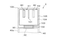
- the recovery unit 200 is a magnetically levitated mobile body that moves when current is applied to the coils of the planar motors 43 and 104. This recovery unit 200 is configured to recover, in the maintenance mode, at least one of the transport unit 70 and the gate valve 80 that is unable to move within the vacuum transport chamber 40a due to a malfunction, to the waiting chamber 100.
- the transport unit 70 and the gate valve 80 can be retrieved as part of maintenance of the vacuum transport chamber 40a without opening the vacuum transport chamber 40a to the atmosphere. Note that in this configuration as well, by using the maintenance device 3, the transport unit 70 and the gate valve 80 provided in the vacuum transport chamber 40a can be replaced without opening the vacuum transport chamber 40a to the atmosphere.
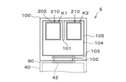
- the magnetic levitation type maintenance unit that waits in the waiting chamber 100 in the substrate processing mode is the recovery unit 200, but it may also be a magnetic levitation type cleaning unit 210 as shown in FIG. 11.
- the cleaning unit 210 is housed in each of the storage spaces K1 and K2.
- the cleaning unit 210 has, for example, plate brushes 211a-211c, links 212a-212c, and a base 213.
- the plate brushes 211a-211c will be referred to as plate brushes 211.
- the links 212a-212c will be referred to as links 212.
- the plate brush 211a is for cleaning the ceiling surface of the vacuum transfer chamber 40a.
- the plate brush 211b is for cleaning the floor surface of the vacuum transfer chamber 40a.
- the plate brush 211c is for cleaning the vertical inner wall surface of the vacuum transfer chamber 40a.
- One end of the link 212 is connected to a base 213 .
- the other end of the link 212a is connected to the plate brush 211a.
- the other end of the link 212b is connected to the plate brush 211b.
- the other end of the link 212c is connected to a plate brush 211c.
- the link 212 can move the corresponding plate brush 211 between a processing position facing the surface to be cleaned and a standby position closer to the base 213 than the processing position.
- Base 213 moves on planar motors 43 and 104 due to the magnetic fields generated by coils 43a of planar motor 43 and coils of planar motor 104.
- the base 213 may be provided with a drive unit (not shown) such as a motor or cylinder that drives the movement of the plate brush 211 by the link 212.
- the base 213 may also be provided with a communication unit (not shown) for communication between the drive unit and the control device 4.
- control device 4 can control the energization of each coil 43a of the planar motor 43, etc., to oscillate the cleaning unit 210 parallel to the brush surface of the plate brush 211 while the plate brush 211 is in contact with the surface to be cleaned.
- the vacuum transport chamber 40a (specifically, its inner wall surface) can be cleaned.
- the vacuum transfer chamber 40a can be cleaned as part of maintenance of the vacuum transfer chamber 40a without opening the vacuum transfer chamber 40a to the atmosphere. Note that in this configuration as well, by using the maintenance device 3, the transfer unit 70 and gate valve 80 provided within the vacuum transfer chamber 40a can be replaced without opening the vacuum transfer chamber 40a to the atmosphere.
- this method of replacing the transfer unit 70 and the gate valve 80 does not require the replacement work to be performed by an operator, so there is no need for the operator to access the inside of the vacuum transfer chamber 40a. Therefore, there is no need to provide an opening for this access in the vacuum transfer chamber 40a, so the inner wall surface of the vacuum transfer chamber 40a can be made as flat as possible.
- the transport unit 70 for transporting the substrate W and the gate valve 80 for opening and closing the first opening 41 are of the magnetic levitation type. This also makes it possible to make the inner wall surface of the vacuum transport chamber 40a as flat as possible. If the inner wall surface of the vacuum transfer chamber 40a is flat, it is easy to clean it with the cleaning unit 210.
- the magnetic levitation type maintenance unit that the maintenance device 5 accommodates in the waiting chamber 100 during the substrate processing mode may be a magnetic levitation type monitoring unit 220, as shown in FIG. 13.
- the upper imaging section 223 and the lower imaging section 224 each have a transparent cover, an imaging element, and a lighting module.
- the transparent cover is made of a transparent material and defines an accommodation space with an atmospheric atmosphere in which the imaging element and the illumination module are accommodated.
- the imaging element of the upper imaging section 223 is provided so as to capture an image above it, and the imaging element of the lower imaging section 224 is provided so as to capture an image below it.
- the illumination module illuminates at least the imaging range of the imaging element.
- the support member 222 may be provided with a storage unit that stores the imaging results obtained by the upper imaging unit 223 and the lower imaging unit 224.
- the support member 222 may also be provided with a communication unit (not shown) that wirelessly communicates the imaging results obtained by the upper imaging unit 223 and the lower imaging unit 224 to the control device 4.
- the transport unit 70 and gate valve 80 installed in the vacuum transport chamber 40a can be replaced without opening the vacuum transport chamber 40a to the atmosphere.
- the maintenance device 3 is detachably connected to the substrate processing apparatus 2 and is connected to the substrate processing apparatus 2 only when the transport unit 70 and the gate valve 80 are replaced, but the maintenance device 3 may be connected to the substrate processing apparatus 2 at times other than the above replacement. That is, the maintenance device 3 may be permanently provided to the substrate processing apparatus 2 as described above. The same applies to the maintenance device 5.
- an opening 106 that connects the waiting chamber 100 to the outside of the maintenance device 3 and a gate valve 107 that opens and closes the opening 106 may be provided on the side opposite (hereinafter referred to as the back side) to the opening 102 side (hereinafter referred to as the front side).
- an operator can replace the transport unit 70 and gate valve 80 in the waiting chamber 100. Specifically, an operator can remove a used transport unit 70 and gate valve 80 from inside the waiting chamber 100 through the opening 106, and can also replenish a used transport unit 70 and gate valve 80 in the waiting chamber 100 through the opening 106.
- an opening 106 and a gate valve 107 may be provided on the rear side of the maintenance device 3.
- the transport unit 70 and the gate valve 80 in the waiting chamber 100 may be replaced as follows. That is, first, with one maintenance device 3 (hereinafter referred to as the first device 3) connected to the substrate processing device 2, the control device 4 connects another maintenance device 3 (hereinafter referred to as the other device 3) to the rear side of the one device 3. This allows the waiting chambers 100 of the one device 3 and the other device 3 to communicate with each other via the opening 106 on the rear side of the one device 3 and the opening 102 on the front side of the other device 3.
- the first device 3 hereinafter referred to as the first device 3
- the other device 3 another maintenance device 3
- control device 4 controls the energization of the coils of the planar motors 104 of the one device 3 and the other device 3 to move the used transport unit 70 and the gate valve 80 from the waiting chamber 100 of the one device 3 to the waiting chamber 100 of the other device 3 via the openings 102 and 106, i.e., remove them.
- control device 4 controls the energization of the coils of the planar motor 104 of the first device 3 and the second device 3 to move the transport unit 70 and the gate valve 80 from the waiting chamber 100 of the second device 3 to the waiting chamber 100 of the first device 3 through the openings 102 and 106. In this manner, the transport unit 70 and the gate valve 80 in the waiting chamber 100 may be replaced.
- the rear side of the maintenance device 5 may be provided with an opening 106 and a gate valve 107, similar to the maintenance device 3 described above. This allows the transport unit 70 and gate valve 80 collected by the recovery unit 200, the recovery unit 200 itself, the cleaning unit 210, and the monitoring unit 220 to be removed from the waiting chamber 100 of the maintenance device 5 connected to the substrate processing apparatus 2, via the opening 106. This removal is performed, for example, in the same manner as the removal of the transport unit 70 and gate valve 80 from the waiting chamber 100 in the maintenance device 3 described above.
- the waiting chamber 100 of the maintenance device 3 and the vacuum transfer chamber 40a are connected by the second opening 42, which is an opening different from the first opening 41 that passes through the substrate processing chamber 60a and the vacuum transfer chamber 40a.
- the waiting chamber 100 of the maintenance device 3 and the vacuum transfer chamber 40a may be connected via the first opening 41.
- the maintenance device 3 may be connected to the part of the vacuum transfer chamber 40a to which the substrate processing chamber 60a is connected. The same applies to the maintenance device 5.
- the maintenance device 3 and the maintenance device 5 may be integrated together, and both the replacement magnetic levitation type moving body and the magnetic levitation type maintenance unit may be housed within a single device. Furthermore, one of the magnetic levitation type maintenance units housed in the maintenance device 5 may have the functions of two or more of the collection unit 200 , the cleaning unit 210 and the monitoring unit 220 . Furthermore, the transport unit 70 housed in the maintenance device 3 may be provided with imaging units corresponding to the upper imaging unit 223 and the lower imaging unit 224 of the monitoring unit 220, and the internal conditions of the vacuum transport chamber 40a and the substrate processing chamber 60a may be monitored by these imaging units.
Landscapes
- Life Sciences & Earth Sciences (AREA)
- Biophysics (AREA)
- Container, Conveyance, Adherence, Positioning, Of Wafer (AREA)
Priority Applications (5)
| Application Number | Priority Date | Filing Date | Title |
|---|---|---|---|
| KR1020267009924A KR20260070449A (ko) | 2023-09-14 | 2024-09-02 | 기판 처리 시스템 및 가동식 메인터넌스 장치 |
| CN202480057187.0A CN121795144A (zh) | 2023-09-14 | 2024-09-02 | 基片处理系统和可移动式维护装置 |
| JP2025545619A JPWO2025057798A1 (cg-RX-API-DMAC7.html) | 2023-09-14 | 2024-09-02 | |
| TW113133805A TW202520419A (zh) | 2023-09-14 | 2024-09-06 | 基板處理系統及可動式維護裝置 |
| US19/557,182 US20260198679A1 (en) | 2023-09-14 | 2026-03-05 | Substrate processing system and movable maintenance apparatus |
Applications Claiming Priority (2)
| Application Number | Priority Date | Filing Date | Title |
|---|---|---|---|
| JP2023149475 | 2023-09-14 | ||
| JP2023-149475 | 2023-09-14 |
Related Child Applications (1)
| Application Number | Title | Priority Date | Filing Date |
|---|---|---|---|
| US19/557,182 Continuation US20260198679A1 (en) | 2023-09-14 | 2026-03-05 | Substrate processing system and movable maintenance apparatus |
Publications (1)
| Publication Number | Publication Date |
|---|---|
| WO2025057798A1 true WO2025057798A1 (ja) | 2025-03-20 |
Family
ID=95021265
Family Applications (1)
| Application Number | Title | Priority Date | Filing Date |
|---|---|---|---|
| PCT/JP2024/031455 Ceased WO2025057798A1 (ja) | 2023-09-14 | 2024-09-02 | 基板処理システム及び可動式メンテナンス装置 |
Country Status (6)
| Country | Link |
|---|---|
| US (1) | US20260198679A1 (cg-RX-API-DMAC7.html) |
| JP (1) | JPWO2025057798A1 (cg-RX-API-DMAC7.html) |
| KR (1) | KR20260070449A (cg-RX-API-DMAC7.html) |
| CN (1) | CN121795144A (cg-RX-API-DMAC7.html) |
| TW (1) | TW202520419A (cg-RX-API-DMAC7.html) |
| WO (1) | WO2025057798A1 (cg-RX-API-DMAC7.html) |
Citations (6)
| Publication number | Priority date | Publication date | Assignee | Title |
|---|---|---|---|---|
| US20210249291A1 (en) * | 2018-06-14 | 2021-08-12 | Robert Bosch Gmbh | Conveying Device for Conveying at Least One Wafer |
| JP2021163783A (ja) * | 2020-03-30 | 2021-10-11 | 東京エレクトロン株式会社 | 清掃装置及び半導体製造システム |
| JP2021176173A (ja) * | 2020-05-01 | 2021-11-04 | 東京エレクトロン株式会社 | 部品交換システムおよび部品交換装置 |
| JP2022113548A (ja) * | 2021-01-25 | 2022-08-04 | 東京エレクトロン株式会社 | 基板の搬送を行う装置、基板を処理するシステム及び基板を処理する方法 |
| JP2022143380A (ja) * | 2021-03-17 | 2022-10-03 | 東京エレクトロン株式会社 | 開閉装置及び搬送室 |
| WO2023077072A1 (en) * | 2021-10-29 | 2023-05-04 | Brooks Automation Us, Llc | Substrate processing apparatus |
Family Cites Families (1)
| Publication number | Priority date | Publication date | Assignee | Title |
|---|---|---|---|---|
| JP7537847B2 (ja) | 2021-03-02 | 2024-08-21 | 東京エレクトロン株式会社 | 基板搬送装置及び基板処理システム |
-
2024
- 2024-09-02 JP JP2025545619A patent/JPWO2025057798A1/ja active Pending
- 2024-09-02 KR KR1020267009924A patent/KR20260070449A/ko active Pending
- 2024-09-02 CN CN202480057187.0A patent/CN121795144A/zh active Pending
- 2024-09-02 WO PCT/JP2024/031455 patent/WO2025057798A1/ja not_active Ceased
- 2024-09-06 TW TW113133805A patent/TW202520419A/zh unknown
-
2026
- 2026-03-05 US US19/557,182 patent/US20260198679A1/en active Pending
Patent Citations (6)
| Publication number | Priority date | Publication date | Assignee | Title |
|---|---|---|---|---|
| US20210249291A1 (en) * | 2018-06-14 | 2021-08-12 | Robert Bosch Gmbh | Conveying Device for Conveying at Least One Wafer |
| JP2021163783A (ja) * | 2020-03-30 | 2021-10-11 | 東京エレクトロン株式会社 | 清掃装置及び半導体製造システム |
| JP2021176173A (ja) * | 2020-05-01 | 2021-11-04 | 東京エレクトロン株式会社 | 部品交換システムおよび部品交換装置 |
| JP2022113548A (ja) * | 2021-01-25 | 2022-08-04 | 東京エレクトロン株式会社 | 基板の搬送を行う装置、基板を処理するシステム及び基板を処理する方法 |
| JP2022143380A (ja) * | 2021-03-17 | 2022-10-03 | 東京エレクトロン株式会社 | 開閉装置及び搬送室 |
| WO2023077072A1 (en) * | 2021-10-29 | 2023-05-04 | Brooks Automation Us, Llc | Substrate processing apparatus |
Also Published As
| Publication number | Publication date |
|---|---|
| KR20260070449A (ko) | 2026-05-19 |
| TW202520419A (zh) | 2025-05-16 |
| US20260198679A1 (en) | 2026-07-16 |
| JPWO2025057798A1 (cg-RX-API-DMAC7.html) | 2025-03-20 |
| CN121795144A (zh) | 2026-04-03 |
Similar Documents
| Publication | Publication Date | Title |
|---|---|---|
| US7833382B2 (en) | Vacuum processing apparatus | |
| US8303764B2 (en) | Apparatus and methods for transporting and processing substrates | |
| US6568552B1 (en) | Systems and methods for low contamination, high throughput handling of workpieces for vacuum processing | |
| CN1269707C (zh) | 模块分选器 | |
| CN102985344B (zh) | 运输和储存盒的处理装置 | |
| JP2011517134A (ja) | クリーン移送ロボット | |
| US20250349573A1 (en) | Substrate processing apparatus | |
| TW201330158A (zh) | 真空處理裝置 | |
| KR20110139629A (ko) | 진공처리장치 | |
| KR102892958B1 (ko) | 개폐 장치 | |
| JP7787678B2 (ja) | 処理システム及び搬送方法 | |
| JP5247094B2 (ja) | 基板処理システム | |
| JP5097627B2 (ja) | 真空処理装置 | |
| JP7767463B2 (ja) | 冗長性のあるファクトリインターフェース | |
| KR102915576B1 (ko) | 검출 장치, 처리 시스템 및 반송 방법 | |
| JP3907889B2 (ja) | 基板搬送装置 | |
| KR20260070449A (ko) | 기판 처리 시스템 및 가동식 메인터넌스 장치 | |
| US20160300734A1 (en) | Substrate processing system | |
| KR20260003273A (ko) | 기판 처리 장치 | |
| TW202603948A (zh) | 搬運裝置 | |
| KR20200098109A (ko) | 반도체 웨이퍼 보관상자 운반 처리 장치 |
Legal Events
| Date | Code | Title | Description |
|---|---|---|---|
| 121 | Ep: the epo has been informed by wipo that ep was designated in this application |
Ref document number: 24865300 Country of ref document: EP Kind code of ref document: A1 |
|
| ENP | Entry into the national phase |
Ref document number: 2025545619 Country of ref document: JP Kind code of ref document: A |
|
| WWE | Wipo information: entry into national phase |
Ref document number: 2025545619 Country of ref document: JP |
|
| NENP | Non-entry into the national phase |
Ref country code: DE |