WO2025053285A1 - プログラム、記憶媒体、情報処理装置、システム及びロボットの動作を制御する方法 - Google Patents
プログラム、記憶媒体、情報処理装置、システム及びロボットの動作を制御する方法 Download PDFInfo
- Publication number
- WO2025053285A1 WO2025053285A1 PCT/JP2024/032211 JP2024032211W WO2025053285A1 WO 2025053285 A1 WO2025053285 A1 WO 2025053285A1 JP 2024032211 W JP2024032211 W JP 2024032211W WO 2025053285 A1 WO2025053285 A1 WO 2025053285A1
- Authority
- WO
- WIPO (PCT)
- Prior art keywords
- singular
- matrix
- value
- jacobian matrix
- command value
- Prior art date
- Legal status (The legal status is an assumption and is not a legal conclusion. Google has not performed a legal analysis and makes no representation as to the accuracy of the status listed.)
- Pending
Links
Images






Classifications
-
- B—PERFORMING OPERATIONS; TRANSPORTING
- B25—HAND TOOLS; PORTABLE POWER-DRIVEN TOOLS; MANIPULATORS
- B25J—MANIPULATORS; CHAMBERS PROVIDED WITH MANIPULATION DEVICES
- B25J9/00—Program-controlled manipulators
- B25J9/10—Program-controlled manipulators characterised by positioning means for manipulator elements
Definitions
- This disclosure relates to a program, a storage medium, an information processing device, a system, and a method for controlling the operation of a robot.
- US Pat. No. 5,999,333 discloses a system for dealing with singularities during the operation of a multi-axis machine that includes a kinematic linkage with multiple joints.
- numerical control is performed using a Jacobian matrix.
- the Jacobian matrix is subjected to singular value decomposition into an orthonormal matrix including singular values, left singular vectors, and right singular vectors, and joints that are singular or close to singular points are determined using the singular value decomposition results, and the Jacobian matrix is modified by transforming columns of the Jacobian matrix associated with the determined joints using the singular values and left singular vectors.
- Patent Document 1 a virtual joint obtained by calculating a left singular vector using a singular value is replaced with a column of a Jacobian matrix associated with the determined joint. As a result, the relationship between the operating speed of the joint and the operating speed of the tip of the link mechanism, which is inherent to the Jacobian matrix, may be lost.
- This disclosure provides a program, storage medium, information processing device, system, and method that realizes new robot operation control corresponding to singular points using singular value decomposition of the Jacobian matrix.
- a program is a program for controlling the movement of a robot including a plurality of joints and a moving part that is moved by the movement of the plurality of joints, and the program performs singular value decomposition on a first Jacobian matrix relating the movement speeds of the plurality of joints to the movement speed of the moving part to generate a second Jacobian matrix including a first matrix including as its elements a first basis vector representing the movement speed space of the joints, a second matrix including as its elements a second basis vector representing the movement speed space of the moving part, and a first singular matrix including as its diagonal elements a singular value, and determines whether the robot is at a singular point and when the robot is at a singular point based on a comparison result between the singular value and a first threshold value.
- the computer is caused to execute the following: determining and executing a process to be executed from a first process executed when the robot is approaching the singular point and a second process executed when the robot is away from the singular point; generating a third Jacobian matrix by transforming diagonal elements in the first singular matrix in the first process; determining and outputting motion command values that command the motion of the multiple joints using the third Jacobian matrix and a motion command value that commands the movement of the moving part in the first process; and determining and outputting the motion command value using the first Jacobian matrix or the second Jacobian matrix and the motion command value in the second process.
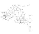
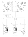
- FIG. 1 is a diagram illustrating an example of a configuration of a robot system according to an exemplary embodiment.
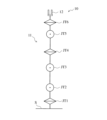
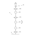
- FIG. 2 is a conceptual diagram showing the configuration of the joints of the robot arm of FIG.
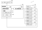
- FIG. 3 is a block diagram illustrating an example of a configuration of a robot system according to an embodiment.
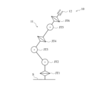
- FIG. 4 is a conceptual diagram showing an example of the posture of the robot arm at a singular point.
- FIG. 5 is a conceptual diagram showing an example of the posture of the robot arm at a singular point.
- FIG. 6 is a conceptual diagram showing an example of the posture of the robot arm at a singular point.
- FIG. 7 is a conceptual diagram showing an example of the posture of the robot arm at a singular point.
- FIG. 1 is a diagram illustrating an example of a configuration of a robot system according to an exemplary embodiment.
- FIG. 2 is a conceptual diagram showing the configuration of the joints of the robot arm of FIG.
- FIG. 3 is a block diagram illustrating an example of a configuration of
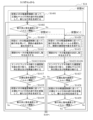
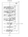
- FIG. 8 is a flowchart illustrating an example of a process related to a singular point in the information processing device according to the embodiment.
- FIG. 9 is a flowchart illustrating an example of a process related to a singular point in the information processing device according to the embodiment.
- FIG. 10 is a flowchart illustrating an example of a process related to a singular point of the information processing device according to the embodiment.
- FIG. 11 is a flowchart illustrating an example of a process related to a singular point in the information processing device according to the embodiment.
- FIG. 12 is a flowchart illustrating an example of a process related to a singular point of the information processing device according to the embodiment.
- FIG. 13A is a conceptual diagram showing an example of self-motion of a robot arm in the case of a shoulder singular posture.
- FIG. 13B is a conceptual diagram showing an example of self-motion of the robot arm in the case of a shoulder singular posture.
- FIG. 13C is a conceptual diagram showing an example of self-motion of the robot arm in the case of a shoulder singular posture.
- FIG. 14 is a diagram illustrating an example of a configuration of a robot system according to a modified example.
- Fig. 1 is a schematic diagram showing an example of the configuration of the robot system 1 according to an embodiment.
- the robot system 1 according to the embodiment includes a robot 10, a control device 20, and a user interface 30.
- the robot system 1 functions as a system for manually controlling the robot 10
- the user interface 30 functions as a manual controller
- the robot 10 operates according to operations input to the manual controller.
- the control device 20 controls the overall operation of the robot system 1.
- the robot 10 includes a link structure 11 and a moving part 12.
- the link structure 11 includes a plurality of links L and a plurality of joints JT that operably connect the plurality of links L.
- the moving part 12 is attached to the link structure 11. In this embodiment, the moving part 12 is attached to the tip of the link structure 11.
- the link structure 11 can move the moving part 12 to various positions and postures by operating the plurality of joints JT.
- the link structure 11 is a multi-joint robot arm, for example, an industrial robot arm, although it is not limited thereto.
- the link structure 11 may have a structure in which multiple links L are connected by multiple joints JT, and may be, for example, a robot leg.
- the link structure 11 has a vertical multi-joint arm structure, and includes six links L1 to L6 and six joints JT1 to JT6 as the multiple links L and multiple joints JT.
- the link structure 11 as a robot arm is not limited to the above, and may have other types of arm structures, such as a horizontal multi-joint type.
- the number of links L and the number of joints JT may also be five or less, or seven or more.
- the link structure 11 may also be referred to as a robot arm 11.
- a “joint” is represented using “joint JT1" to "joint JT6" when the joints are to be distinguished, and is represented as “joint JT” when the joints are not to be distinguished.
- a “link” is represented using “link L1” to "link L6" when the links are to be distinguished, and is represented as “link L” when the links are not to be distinguished.
- FIG. 2 is a conceptual diagram showing the configuration of the joints of the robot arm 11 of FIG. 1.
- the robot arm 11 is fixed to the base 13 at its base.
- Links L1 to L6 are arranged in order from the base to the tip of the robot arm 11.
- Joint JT1 connects link L1 to the base 13 so as to be rotatable around axis A1.
- Joint JT2 connects link L2 to link L1 so as to be rotatable around axis A2.
- the direction of axis A2 intersects with, and is, for example, perpendicular to, the direction of axis A1.
- Joint JT3 connects link L3 to link L2 so as to be rotatable around axis A3.
- the direction of axis A3 is along, and is, for example, parallel to, the direction of axis A2.
- Joint JT4 connects link L4 to link L3 so as to be rotatable around axis A4.
- the direction of axis A4 intersects with, and is, for example, perpendicular to, the direction of axis A3.
- Joint JT5 connects link L5 to link L4 so that the link can rotate around axis A5.
- the direction of axis A5 intersects, for example, is perpendicular to, the direction of axis A4.
- Joint JT6 connects link L6 to link L5 so that the link can rotate around axis A6.
- the direction of axis A6 intersects, for example, is perpendicular to, the direction of axis A5.
- All of the joints JT1 to JT6 of the vertically articulated robot arm 11 are rotary joints, but at least one of the joints JT1 to JT6 may be a linear joint.
- the joints JT1 to JT3 may be linear joints.
- the singular points of the robot arm 11, which will be described later, will be different.
- Link L6 includes a mechanical interface at its tip, and is connected to the moving unit 12 via the mechanical interface.
- the moving unit 12 can send and receive signals and receive power via the mechanical interface.
- the moving unit 12 has a structure that can apply an action to an object, and is also called an end effector.
- the action of the moving unit 12 is not particularly limited, but in this embodiment, it is the action of grasping an object. Below, the moving unit 12 may also be called the end effector 12.
- the robot arm 11 includes driving devices D1 to D6 that drive the joints JT1 to JT6, respectively.
- the driving devices D1 to D6 each include a motor M1 to M6 as a driving source, and may further include a reducer that transmits the rotational driving force of the motors M1 to M6.
- FIG. 3 is a block diagram showing an example of the configuration of the robot system 1 according to the embodiment.
- the motors M1 to M6 are each a servo motor, and include an electric motor and a rotation sensor E such as an encoder that detects the amount of rotation of the electric motor.
- the operation of the motors M1 to M6 is controlled by the control device 20.
- the control device 20 feedback-controls the motors M1 to M6 using the current values applied to the motors M1 to M6 and the detection results of the respective rotation sensors E as feedback information.
- the user interface 30 is connected to the control device 20 via wired communication, wireless communication, or a combination thereof. Any wired or wireless communication may be used.
- the user interface 30 accepts input from an operator and outputs a signal based on the input to the control device 20.
- the user interface 30 accepts input of an operation for manually operating the robot arm 11.
- the input is related at least to a target velocity of the end effector 12 moved by the robot arm 11.
- the target velocity includes a target direction of movement of the end effector 12 and a target speed of the end effector 12 in the direction of movement.
- the user interface 30 outputs a signal to the control device 20 commanding a target velocity of the end effector 12 according to the input for manual operation.
- the user interface 30 accepts input of information related to the specifications of the robot 10 and outputs a signal representing the information to the control device 20.
- the information may include the number and length of the links L, the number and type of the joints JT, the joints JT connected to each link L, and the position and direction of the axis A of the joints JT connected to each link L.
- the length of the link L may be the length of the link L itself, or may be the distance between two joints JT connected to the link L.
- the type of the joint JT may represent a rotary joint or a prismatic joint.
- the position of the axis A of the joint JT may represent the position of the rotation axis of the rotary joint or the position of the prismatic axis of the prismatic joint with respect to the link L to which the joint JT is connected.
- the position of the axis A of the joint JT may represent the relative position between the two axes A of the two joints JT connected to the link L, and may represent, for example, the distance between the two axes A.
- the direction of the axis A of the joint JT may represent the direction of the rotation axis of the rotary joint or the direction of the prismatic axis of the prismatic joint with respect to the link L to which the joint JT is connected.
- the direction of the axis A of the joint JT may represent the relative direction between the two axes A of the two joints JT connected to the link L, and may represent, for example, the angle between the two axes A.
- the user interface 30 may be a maneuvering arm having a structure similar to the robot arm 11, a known operating device for a robot, a known teaching device for a robot such as a teach pendant, a computer such as a personal computer, a smart device such as a smartphone or tablet, a game terminal, other operating device, other terminal device, a device that uses these, a device that has been improved upon these, or a combination of two or more of the above devices.
- the user interface 30 may include, as an input means, a device that receives input via operation by an operator, such as a button, a lever, a dial, a joystick, a mouse, keys, a touch panel, motion capture, or a combination of two or more of these.
- the user interface 30 includes a joystick.
- the direction of tilt of the joystick represents the direction of movement of the target of the end effector 12, and the angle of tilt of the joystick can represent the speed of the target of the end effector 12 in that direction of movement.
- the control device 20 is connected to the robot 10 via wired communication, wireless communication, or a combination of these. Any wired or wireless communication may be used.
- the control device 20 controls the operation of the robot 10 according to commands contained in signals received from the user interface 30.
- the control device 20 determines elements to be included in the control program of the robot 10 using information about the specifications of the robot 10 contained in signals received from the user interface 30.
- the control device 20 also controls the power supply to the robot 10.
- the control device 20 includes an information processing device 100 and a power control circuit 200.
- the information processing device 100 and the power control circuit 200 are included in one control device 20, but are separate devices separate from each other and may be connected to each other via wired communication, wireless communication, or a combination of these. Any wired communication and wireless communication may be used.
- the power control circuit 200 includes one or more of an amplifier, a converter, and an inverter, and controls the power supplied to the robot 10.
- the power control circuit 200 supplies current to the motors M1 to M6 of the drive devices D1 to D6 of the robot arm 11 according to the current value included in the command received from the information processing device 100.
- the information processing device 100 includes a circuit C, which includes a processor P and a memory M.
- the circuit C may include a processing circuit.
- the information processing device 100 may be an electronic circuit board, an electronic control unit, a microcomputer, a personal computer, a workstation, a smart device such as a smartphone or a tablet, or other electronic device.
- the memory M stores the program executed by the processor P and various data.
- the memory M stores the control program for the robot 10.
- the information processing device 100 may further include a hard disk drive (HDD: Hard Disk Drive) or a solid state drive (SSD: Solid State Drive) as a storage means.
- the memory M includes RAM (Random Access Memory), which is a volatile memory, and ROM (Read-Only Memory), which is a non-volatile memory.
- the processor P together with the RAM and ROM, forms a computer system.
- the computer system may realize the functions of the information processing device 100 by the processor P using the RAM as a work area to execute a program recorded in the ROM. Some or all of the functions of the information processing device 100 may be realized by the computer system, by a dedicated hardware circuit such as an electronic circuit or integrated circuit, or by a combination of the computer system and the hardware circuit.
- the information processing device 100 may be configured to execute each process by centralized control by a single device, or may be configured to execute each process by distributed control through the cooperation of multiple devices.
- the processor P may include a CPU (Central Processing Unit), an MPU (Micro Processing Unit), a GPU (Graphics Processing Unit), a microprocessor, a processor core, a multiprocessor, an ASIC (Application-Specific Integrated Circuit), an FPGA (Field Programmable Gate Array), etc.
- the processor P may realize each process by a logic circuit or a dedicated circuit formed in an IC (Integrated Circuit) chip, an LSI (Large Scale Integration), etc. Multiple processes may be realized by one or multiple integrated circuits, or may be realized by a single integrated circuit.
- the information processing device 100 converts the target velocity of the end effector 12 contained in the signal received from the user interface 30 into a target velocity for each of the joints JT1 to JT6.
- the robot arm 11 can move the end effector 12 at the target velocity.
- the velocity of the joint JT includes the direction of motion of the joint JT and the speed of motion of the joint JT in that direction.
- the rotation angle of the rotational joint and the linear motion position of the linear joint are both expressed by a phase based on the joint, and the velocity of the joint is obtained by time-differentiating the phase.
- the phase of the joint JT is represented by ⁇
- the velocity of the joint JT is represented by a velocity ⁇ va.
- the control program stored in the memory M includes a matrix J called the Jacobian matrix.
- the inverse matrix J of the Jacobian matrix J is used to convert the target velocity.
- the Jacobian matrix J is a matrix that converts the small displacements of the joints JT1 to JT6 into small displacements of the position and orientation of the end effector 12.
- the position and orientation of the mechanical interface surface of link L6 are represented as the position and orientation of the end effector 12.
- the position and orientation of the mechanical interface surface are represented by coordinates in a robot coordinate system ⁇ (X,Y,Z) based on the robot 10.
- the robot coordinate system ⁇ (X,Y,Z) has an origin at the connection between the base 13 and the support surface S of the base 13, and includes an X-axis and a Y-axis that extend perpendicular to each other along the support surface S, and a Z-axis that is perpendicular to the X-axis and the Y-axis.
- the position of the mechanical interface surface is represented by x, y, and z, which are coordinates in the robot coordinate system ⁇ (X,Y,Z) of the origin of the mechanical interface coordinate system ⁇ (Xm,Ym,Zm) based on the mechanical interface surface.
- the origin of the mechanical interface coordinate system ⁇ (Xm,Ym,Zm) is located at the center of the mechanical interface surface.
- the attitude of the mechanical interface surface is represented by angles rO , rA , and rT that the mechanical interface coordinate system ⁇ (Xm,Ym,Zm) makes with the robot coordinate system ⁇ (X,Y,Z).
- the angles rO , rA , and rT may be represented by roll angle, pitch angle, and yaw angle, or may be represented by Euler angles.
- [ xv , yv , zv ] represents a translational velocity vector, and xv , yv , and zv represent the velocities in the X-axis, Y-axis, and Z-axis directions, respectively, in the robot coordinate system ⁇ (X,Y,Z).
- [ ⁇ x , ⁇ y , ⁇ z ] represents an angular velocity vector, and ⁇ x , ⁇ y , and ⁇ z represent the angular velocities around the X-axis, Y-axis, and Z-axis, respectively, in the robot coordinate system ⁇ (X,Y,Z).
- the information processing device 100 operates according to a control program to determine the target speed of each of the joints JT1 to JT6 using the above relational expression and the target speed of the end effector 12. Furthermore, the information processing device 100 determines the current values to be applied to the motors M1 to M6 in order to operate the joints JT1 to JT6 at the target speeds, and outputs the current values to the power control circuit 200.
- the Jacobian matrix J is a matrix that depends on the specifications of the robot 10, and can be calculated using information on the specifications of the robot 10.
- the information processing device 100 receives information on the specifications of the robot 10 from another device such as the user interface 30, the information processing device 100 stores the information in the memory M.
- the information processing device 100 operates according to a control program, and calculates the Jacobian matrix J using the phases ⁇ 1, ⁇ 2, ⁇ 3, ⁇ 4, ⁇ 5, and ⁇ 6 of the joints JT1 to JT6 based on the feedback information and information on the specifications of the robot 10, and stores the Jacobian matrix J in the memory M.
- the information processing device 100 applies the target velocity of the end effector 12 to the inverse matrix J -1 of the Jacobian matrix J to determine the target velocity of the joints JT1 to JT6.
- the information processing device 100 can obtain information about the specifications of the changed robot 10, calculate the Jacobian matrix J that is suitable for the changed robot 10, and perform disassembly rate control according to the changed robot 10.
- the information processing device 100 determines the excessive speed required for the joints JT1 to JT6 as an error, and stops the operation of the joints JT1 to JT6.
- the robot arm 11 may not be able to achieve a sufficient velocity of the joints JT1 to JT6 to generate a velocity of the end effector 12 in the above-mentioned direction, and the trajectory of the end effector 12 may deviate from the originally commanded trajectory.
- the robot arm 11 may perform a self-motion in which the movement of a part of the end effector 12, etc. is stopped and the stopped part is maintained in position while operating. In the vicinity of a singular point, the robot arm 11 may move the end effector 12 at a speed that changes suddenly with respect to the target speed as the singular point is approached.
- Figures 4 to 7 are conceptual diagrams showing examples of postures of the robot arm 11 at a singular point.
- Figure 4 shows a fully extended posture of the robot arm 11 in which the joints JT1 to JT6 are aligned in a straight line.
- Figures 5 to 7 show postures of the robot arm 11 in which two or more of the joints JT1 to JT6 are aligned in a straight line.
- the joints JT2 to JT4 including the joint JT3 corresponding to the elbow joint of the robot arm 11, are aligned in a straight line.
- Such a posture of the robot arm 11 is also called an elbow singular posture.
- steps S1 and S2 are preliminary steps for controlling the robot 10 in accordance with the speed command for the end effector 12 output from the user interface 30.
- the steps from step S3 onwards are related to the control of the robot 10.
- step S1 the user of the robot system 1 inputs information about the specifications of the robot 10 to the user interface 30.
- the user interface 30 transmits the information, and the control device 20 receives the information.
- step S4 the information processing device 100 receives, as feedback information, from the power control circuit 200, the current values applied to the motors M1 to M6 of the joints JT1 to JT6 and the detection results of the rotation sensors E from the motors M1 to M6.
- the information processing device 100 may obtain the feedback information at every predetermined sampling period.
- step S5 the information processing device 100 calculates the phases ⁇ 1, ⁇ 2, ⁇ 3, ⁇ 4, ⁇ 5, and ⁇ 6 of joints JT1 to JT6 using the detection results of rotation sensor E included in the feedback information.
- the information processing device 100 calculates the Jacobian matrix J using the phases ⁇ 1, ⁇ 2, ⁇ 3, ⁇ 4, ⁇ 5, and ⁇ 6 and information related to the specifications of the robot 10 stored in memory M.
- the Jacobian matrix J is an example of a first Jacobian matrix. Therefore, steps S4 and S5 may be performed in the reverse order.
- step S6 the information processing device 100 normalizes the Jacobian matrix J.
- v i max and ⁇ vai max may be set based on the specifications of the robot 10.
- d v and d ⁇ v are correction coefficients that satisfy 1 ⁇ d v ⁇ m and 1 ⁇ d ⁇ v ⁇ n, respectively.
- m is the number of dimensions of the velocity vector V, which is 6 in this example.
- n is the number of dimensions of the velocity vector ⁇ v , which is 6 in this example.
- the robot arm 11 is a non-redundant manipulator.
- the velocity vectors V and V Ne are examples of movement command values
- the velocity vectors ⁇ v and ⁇ vN are examples of operation command values.
- [x v , y v , z v ] can be expressed as a translation vector vl, and [ ⁇ x , ⁇ y , ⁇ z ] can be expressed as an angular velocity vector ⁇ .
- the translation vector vl and the angular velocity vector ⁇ are in different units. Therefore, as shown in the following formula 3, the velocity vector V may be normalized to a velocity vector VN using the maximum norm ⁇ vl ⁇ max of the translation vector vl and the maximum norm ⁇ l ⁇ max of the angular velocity vector ⁇ .
- the correction coefficient d v satisfies 1 ⁇ d v ⁇ 2.
- I 3 is a unit matrix of 3 rows by 3 columns.
- of the normalized velocity vector VN satisfies
- step S7 the information processing device 100 performs singular value decomposition on the normalized Jacobian matrix JN to generate a matrix set M1 including three matrices Uv, ⁇ , and V ⁇ .
- the matrix Uv is an orthonormal system
- the matrix V ⁇ is an orthonormal system
- "n" for the column vector u vi is the number of dimensions of the velocity of the end effector 12
- "n" for the row vector v ⁇ i is the number of dimensions of the velocity of the multiple joints JT. The closer the posture of the robot arm 11 is to a singular point, the smaller the minimum singular value ⁇ n becomes.
- the matrix set M1 is an example of a second Jacobian matrix.
- the matrix V ⁇ T is an example of a first matrix
- the matrix U v is an example of a second matrix
- the matrix ⁇ is an example of a first singular matrix
- the vector v ⁇ i is an example of a first basis vector
- the vector u vi is an example of a second basis vector.
- the inverse matrix of the normalized Jacobian matrix JN i.e., the inverse matrix of the matrix set M1
- the inverse matrix of the matrix set M1 is an example of a second inverse Jacobian matrix.
- the matrix V ⁇ is an example of a first transformation matrix
- the matrix UVT is an example of a second transformation matrix
- the matrix ⁇ -1 is an example of a first transformation singular matrix.
- the velocity command value V of the end effector 12 can be normalized to a velocity vector VN using Equation 1.
- the normalized velocity vector VN can be expressed as shown in Equation 7 below using its norm ⁇ VN ⁇ and the unit vector uN of the normalized velocity vector VN .
- a velocity vector ⁇ vN obtained by normalizing the velocity vector ⁇ v of the joints JT1 to JT6 for moving the end effector 12 in accordance with the velocity command value V is expressed as the following equation 8 using equations 6 and 7.
- of the normalized velocity vector ⁇ vN may not satisfy
- ⁇ 1 is guaranteed. Therefore, in order to generate a command value for the operation of the robot arm 11, the normalized velocity vector ⁇ vN1 can be used instead of the normalized velocity vector ⁇ vN , and thus the resolved velocity control according to Equation 8 can be changed to the resolved velocity control according to Equation 9.
- step S10 the information processing device 100 performs disassembly speed control according to state 0, setting the speed command value V of the end effector 12 to 0.
- step S10 includes steps S1001 to S1008, the details of which will be described later.
- step S9 the information processing device 100 determines whether the posture of the robot arm 11 is at a singularity or in an area near a singularity. If the posture of the robot arm 11 is at a singularity or in an area near a singularity (Yes in step S9), the information processing device 100 proceeds to step S11, and if the posture of the robot arm 11 is not at a singularity or in an area near a singularity (No in step S9), the information processing device 100 proceeds to step S12.
- step S9 the information processing device 100 performs processing based on the comparison result between the minimum singular value ⁇ n and the threshold ⁇ ⁇ n . If ⁇ n ⁇ ⁇ ⁇ n , the information processing device 100 determines that the posture of the robot arm 11 is in a singular point or in a region near a singular point, and if ⁇ n ⁇ ⁇ ⁇ n , the information processing device 100 determines that the posture of the robot arm 11 is neither in a singular point nor in a region near a singular point.
- the threshold ⁇ ⁇ n is an example of a first threshold.
- the threshold ⁇ ⁇ n is a threshold set to a value other than 0 for the minimum singular value ⁇ n .
- the threshold ⁇ ⁇ n may be set based on an empirical rule for the minimum singular value ⁇ n such that the norm ⁇ vN ⁇ of the normalized velocity vector ⁇ vN expressed as in Equation 8 satisfies ⁇ vN ⁇ >1.
- step S12 the information processing device 100 performs decomposition speed control according to state NS (Non Singular), which is decomposition speed control in the normal state.
- state NS Non Singular
- step S12 includes steps S1201 to S1209, the details of which will be described later.
- step S11 the information processing device 100 calculates the contribution wn of the direction of the basis vector u vn of the velocity space of the end effector 12 in the normalized command velocity vector V N of the end effector 12 based on Equation 8, as shown in the following Equation 10.
- the vector u N is a unit vector of the normalized velocity vector V N.
- the range that the contribution wn can take is 0 ⁇ w n ⁇ 1.
- the contribution wn indicates the degree to which the direction of the command velocity of the end effector 12 contributes to the directional component of the velocity of the end effector 12 that cannot be realized by the robot arm 11 in a singular point state. The closer the contribution wn is to 1, the greater the degree of contribution.
- step S13 the information processing device 100 determines whether the contribution degree wn is equal to or greater than a threshold value ⁇ wn . If the contribution degree wn is equal to or greater than the threshold value ⁇ wn (Yes in step S13), the information processing device 100 proceeds to step S14, and if the contribution degree wn is less than the threshold value ⁇ wn (No in step S13), the information processing device 100 proceeds to step S15.
- the threshold value ⁇ wn is set in the range of 0 ⁇ ⁇ wn ⁇ 1.
- the threshold value ⁇ wn is an example of a third threshold value.
- step S14 the information processing device 100 performs decomposition speed control according to state SC (Singularity Consistent).
- State SC is decomposition speed control in a state where the contribution at the singularity or in the area near the singularity is equal to or greater than a threshold.
- step S14 includes steps S1401 to S1429, the details of which will be described later.
- step S15 the information processing device 100 performs decomposition speed control according to state P (Perpendicular).
- State P is decomposition speed control in a state where the contribution at the singularity or in the area near the singularity is smaller than a threshold value.
- step S15 includes steps S1501 to S1511, the details of which will be described later.
- step S1001 the information processing device 100 sets the speed command value V of the end effector 12 to 0, determines a speed command value for stopping the operation of joints JT1 to JT6, and outputs a command value for stopping the rotation of motors M1 to M6 of joints JT1 to JT6 to the power control circuit 200.
- step S1002 the power control circuit 200 stops the rotation of motors M1 to M6, thereby stopping the operation of the robot arm 11.
- step S1003 the information processing device 100 obtains a new speed command value for the end effector 12 from the signal received from the user interface 30, similar to step S3.
- step S1004 the information processing device 100 acquires new feedback information for the robot 10, similar to step S4.
- step S1005 the information processing device 100 calculates the Jacobian matrix J using the new speed command value and the new feedback information, similar to step S5.
- step S1006 the information processing device 100 normalizes the Jacobian matrix J, similar to step S6.
- step S1007 the information processing apparatus 100 performs singular value decomposition on the normalized Jacobian matrix J N in the same manner as in step S7.
- step S1008 similarly to step S8, the information processing device 100 determines whether or not the norm ⁇ V N ⁇ of the normalized command velocity V N is equal to or greater than the threshold value ⁇ V. If the norm ⁇ V N ⁇ is equal to or greater than the threshold value ⁇ V (Yes in step S1008), the information processing device 100 proceeds to step S9, and if the norm ⁇ V N ⁇ is less than the threshold value ⁇ V (No in step S1008), the information processing device 100 returns to step S1001 and repeats the subsequent processes.
- step S1201 the information processing device 100 generates velocity command values for the joints JT1 to JT6 by processing according to the decomposition speed control of the state NS.
- the information processing device 100 normalizes the velocity command value V of the end effector 12 to a velocity vector VN according to Equation 3.
- the information processing device 100 applies the normalized velocity vector VN to Equation 9 to calculate a normalized velocity vector ⁇ vN1 for the joints JT1 to JT6.
- the information processing device 100 calculates the velocity command value ⁇ v for the joints JT1 to JT6 by returning the normalized velocity vector ⁇ vN1 to a non-normal form. This ensures that the velocities of the joints JT1 to JT6 are equal to or lower than the upper limit velocity set for the joints JT1 to JT6.
- step S1202 the information processing device 100 uses the difference between the velocities of the joints JT1 to JT6 obtained from the detection results of the rotation sensor E included in the feedback information and the velocity command value ⁇ v , and the current values of the motors M1 to M6 included in the feedback information, to determine the current values to be applied to the motors M1 to M6 to operate the joints JT1 to JT6 according to the velocity command value ⁇ v .
- the information processing device 100 outputs a command for the determined current value to the power control circuit 200, and the power control circuit 200 drives the motors M1 to M6 according to the current value, causing the robot arm 11 to operate.
- step S1203 the information processing device 100 obtains a new speed command value for the end effector 12 from the signal received from the user interface 30, similar to step S1003.
- steps S1204 to S1207 the information processing device 100 performs the same processing as in steps 1004 to S1007 using the new speed command value.
- step S1208 similarly to step S1008, the information processing device 100 determines whether or not the norm ⁇ V N ⁇ of the normalized command velocity V N is equal to or greater than the threshold value ⁇ V. If the norm ⁇ V N ⁇ is equal to or greater than the threshold value ⁇ V (Yes in step S1208), the information processing device 100 proceeds to step S1209, and if the norm ⁇ V N ⁇ is less than the threshold value ⁇ V (No in step S1208), the information processing device 100 proceeds to step S1001 of step S10.
- step S1209 the information processing device 100 determines whether the posture of the robot arm 11 is at a singularity or in an area near a singularity, similar to step S9. If the posture of the robot arm 11 is at a singularity or in an area near a singularity (Yes in step S1209), the information processing device 100 proceeds to step S11, and if the posture of the robot arm 11 is not at a singularity or in an area near a singularity (No in step S1209), the information processing device 100 returns to step S1201 and repeats the subsequent processes.
- step S1401 the information processing device 100 performs processing according to the decomposition speed control of the state SC.
- the information processing device 100 converts the inverse matrix J N -1 of the normalized Jacobian matrix J N shown in Equation 6 to calculate a new matrix J ⁇ N as shown in the following Equation 11.
- the matrix J ⁇ N is also a normalized matrix.
- the information processing device 100 multiplies all elements of the matrix ⁇ -1 in the inverse matrix J N -1 of Equation 6 by ⁇ n/ ⁇ ⁇ n so as to maintain the ratio between the singular value elements 1/ ⁇ 1 , ..., 1/ ⁇ n included in the inverse matrix J N -1 .
- the matrix J ⁇ N is an example of a third inverse Jacobian matrix, and the inverse matrix of the matrix J ⁇ N is an example of a third Jacobian matrix.
- the transformation from the inverse matrix J N -1 to the matrix J ⁇ N is an example of a first transformation, and ⁇ n/ ⁇ ⁇ n is an example of a first ratio.
- the information processing device 100 can perform processing according to the decomposition speed control as shown in the following formula 12 based on formula 11, similarly to formula 9.
- the information processing device 100 can generate a normalized velocity vector ⁇ vNA corresponding to the velocity command values of the joints JT1 to JT6 in accordance with a normalized velocity vector V N corresponding to the velocity command value of the end effector 12 at the singular point or in a region near the singular point. Then, the norm
- the matrix J ⁇ N in equation 12 becomes a matrix as shown in the following equation 13. This corresponds to the null space that causes the robot arm 11 to perform self-motion at the singular point.
- step S1410 the information processing device 100 performs processing according to the decomposition speed control of the state SC-1.
- the information processing device 100 generates speed command values for the joints JT1 to JT6 according to the decomposition speed control shown in Equation 12 using the matrix J ⁇ N .
- the information processing device 100 normalizes the speed command value V of the end effector 12 to a speed vector VN , as in step S1201. Furthermore, the information processing device 100 applies the normalized speed vector VN to Equation 12 to calculate the normalized speed vector ⁇ vNA of the joints JT1 to JT6.
- the singular value elements which are diagonal elements in the matrix J ⁇ N of Equation 11, do not diverge even when the robot arm 11 approaches a singular state.
- the norm ⁇ vNA ⁇ of the speed vector ⁇ vNA satisfies ⁇ vNA ⁇ 1.
- step S1411 the information processing device 100 determines the current values to be applied to the motors M1 to M6 for operating the joints JT1 to JT6 according to the speed command value, as in step S1202.
- the information processing device 100 outputs a command for the determined current value to the power control circuit 200, and the power control circuit 200 drives the motors M1 to M6 according to the current value, causing the robot arm 11 to operate.
- step S1419 the information processing apparatus 100 determines whether or not the norm ⁇ J ⁇ N uN ⁇ of the normalized matrix J ⁇ N and the normalized command velocity vector VN of the end effector 12 is less than the threshold value ⁇ . If the norm ⁇ J ⁇ N uN ⁇ is less than the threshold value ⁇ (Yes in step S1419 ) , the information processing apparatus 100 returns to step S1402, and if the norm ⁇ J ⁇ N uN ⁇ is equal to or greater than the threshold value ⁇ (No in step S1419), the information processing apparatus 100 returns to step S1410 and repeats the subsequent processes.
- step S1420 the information processing device 100 performs processing according to the decomposition speed control of the state SC-2.
- the information processing device 100 performs processing according to the decomposition speed control shown in the following equation 14, instead of equation 12.
- the norm ⁇ J ⁇ N u N ⁇ is replaced with the threshold value ⁇ ⁇ and fixed to a constant. This suppresses instability in the numerical calculation of the joint speed when the norm ⁇ J ⁇ N u N ⁇ becomes too small.
- the information processing device 100 generates speed command values for the joints JT1 to JT6 according to the decomposition speed control shown in equation 14, which uses the matrix J ⁇ N and fixes the norm ⁇ J ⁇ N u N ⁇ .
- the information processing device 100 applies the normalized velocity vector VN of the velocity command value V of the end effector 12 to equation 14 to calculate the normalized velocity vector ⁇ vNB of the joints JT1 to JT6.
- Each element of the normalized velocity vector ⁇ vNB indicates a velocity according to the magnitude of the norm ⁇ J ⁇ N uN ⁇ .
- Each element of the normalized velocity vector ⁇ vNB continuously and gradually reduces the velocity of the joints JT1 to JT6 as the norm ⁇ J ⁇ N uN ⁇ becomes smaller.
- the norm ⁇ vNB ⁇ of the normalized velocity vector ⁇ vNB satisfies ⁇ vNB ⁇ 1. Furthermore, similarly to step S1410, the direction in which the robot arm 11 moves the end effector 12 by operating the joints JT1 to JT6 according to the normalized velocity vector ⁇ vNB does not change from the moving direction of the end effector 12 according to the normalized velocity vector ⁇ vN calculated in step S1201 of the resolved velocity control of the state NS. Therefore, the robot arm 11 can move the end effector 12 in the direction of the command velocity of the end effector 12 without causing the end effector 12 to deviate from the target trajectory near the singular point and without suddenly stopping due to an error in which the joint velocity exceeds the upper limit at the singular point.
- step S1421 the information processing device 100 determines the current values to be applied to the motors M1 to M6 for operating the joints JT1 to JT6 according to the speed command value, similar to step S1411.
- the information processing device 100 outputs a command for the determined current value to the power control circuit 200, and the power control circuit 200 drives the motors M1 to M6 according to the current value, causing the robot arm 11 to operate.
- the information processing apparatus 100 acquires a new velocity command value for the end effector 12 from the signal received from the user interface 30, calculates the normalized Jacobian matrix J N , and performs singular value decomposition, similarly to steps S1412 to S1416.
- step S1427 similarly to step S1417, if the norm ⁇ V N ⁇ of the normalized command velocity V N is greater than or equal to the threshold value ⁇ V (Yes in step S1427), the information processing device 100 proceeds to step S1428, and if the norm ⁇ V N ⁇ is less than the threshold value ⁇ V (No in step S1427), the information processing device 100 proceeds to step S1001 of step S10.
- step S1428 similarly to step S1418, the information processing apparatus 100 converts the inverse matrix J N -1 of the normalized Jacobian matrix J N calculated in steps S1422 to S1426 to calculate a new matrix J ⁇ N .
- step S1429 the information processing apparatus 100 determines whether or not the norm ⁇ J ⁇ N uN ⁇ of the normalized matrix J ⁇ N and the normalized command velocity vector VN of the end effector 12 is equal to or greater than the threshold value ⁇ . If the norm ⁇ J ⁇ N uN ⁇ is equal to or greater than the threshold value ⁇ (Yes in step S1429), the information processing apparatus 100 returns to step S1402, and if the norm ⁇ J ⁇ N uN ⁇ is less than the threshold value ⁇ (No in step S1429), the information processing apparatus 100 returns to step S1420 and repeats the subsequent processes.
- step S1501 the information processing device 100 generates a new matrix J ⁇ NA , which is a matrix obtained by converting the normalized matrix J ⁇ N of equation 11 in step S1401 and is shown in the following equation 15.
- the matrix J ⁇ NA is also a normalized matrix. In the above conversion, the element 1/ ⁇ n of the normalized matrix J ⁇ N is replaced with 0.
- the matrix J ⁇ NA is an example of a fourth inverse Jacobian matrix.
- the directional component of the command velocity of the end effector 12 that cannot be generated due to a singular state is very small.
- a directional component of the velocity is a velocity component associated with the singular value element 1/ ⁇ n .
- the normalized velocity vector ⁇ vNA can realize the movement of the end effector 12 in accordance with the direction of the command velocity of the end effector 12, but the magnitude of the velocity of the end effector 12 is very small.
- step S1502 the information processing device 100 generates velocity command values for the joints JT1 to JT6 in accordance with the decomposed velocity control shown in the following equation 17 using the normalization matrix J ⁇ NA .
- step S1201 the information processing device 100 applies the normalized velocity vector VN of the velocity command value V of the end effector 12 to equation 17 to calculate the normalized velocity vector ⁇ vNC of the joints JT1 to JT6.
- the normalized velocity vector ⁇ vNC corresponds to a velocity command value for the robot arm 11 that is no longer in a singular state due to the dimension being reduced by one by regarding the velocity component in the direction of the singular value element 1/ ⁇ ⁇ n in the command velocity (hand velocity) of the end effector 12 as nonexistent. Therefore, even if the robot arm 11 is in a singular state, the normalized velocity vector ⁇ vNC can approximately realize the command velocity of the end effector 12 for the robot arm 11. Furthermore, the norm ⁇ vNC ⁇ of the normalized velocity vector ⁇ vNC satisfies ⁇ vNC ⁇ 1.
- the robot arm 11 can move the end effector 12 in the direction of the command velocity of the end effector 12 without causing the end effector 12 to deviate from the target trajectory near the singular point and without suddenly stopping due to an error that the joint velocity exceeds the upper limit at the singular point.
- the information processing device 100 proceeds to step S1503 after step S1502.
- the direction of the command velocity of the end effector 12 may change due to the operation of the user interface 30 by the operator, and the contribution wn may decrease from a state equal to or greater than the threshold ⁇ wn to a state less than the threshold ⁇ wn .
- the robot arm 11 moves the end effector 12 at a velocity according to the normalized velocity vector ⁇ vNA of equation 12 in step S1401 or the normalized velocity vector ⁇ vNB of equation 14 in step S1420.
- the robot arm 11 moves the end effector 12 at a velocity according to the normalized velocity vector ⁇ vNC of equation 17.
- the normalized velocity vector ⁇ vNC corresponds to a velocity command value for the robot arm 11 in which the number of dimensions of the velocity is reduced by one and which is not in a singular state, and can approximately realize the command velocity of the end effector 12. Therefore, when the contribution w n from the state SC becomes less than the threshold value ⁇ w n , there is a possibility that the state transitions to state P, and the end effector 12 of the robot arm 11 suddenly moves at a certain velocity. However, as can be seen from FIG. 10 to FIG. 12, in order to transition from the state SC to the state P, it is necessary to transition to state 0 or state NS once, so that the end effector 12 does not suddenly start moving in this way. Furthermore, the information processing device 100 can notify the operator of the change in velocity and prompt him to adjust the operation of the user interface 30.
- step S1503 the information processing device 100 determines the current values to be applied to the motors M1 to M6 for operating the joints JT1 to JT6 according to the speed command value, as in step S1202.
- the information processing device 100 outputs a command for the determined current value to the power control circuit 200, and the power control circuit 200 drives the motors M1 to M6 according to the current value, causing the robot arm 11 to operate.
- steps S1504 to S1508 the information processing apparatus 100 acquires a new velocity command value for the end effector 12 from the signal received from the user interface 30, calculates the normalized Jacobian matrix J N , and performs singular value decomposition, similarly to steps S1203 to S1207.
- step S1509 similarly to step S1208, if the norm ⁇ V N ⁇ of the normalized command velocity V N is greater than or equal to the threshold value ⁇ V (Yes in step S1509), the information processing device 100 proceeds to step S1510, and if the norm ⁇ V N ⁇ is less than the threshold value ⁇ V (No in step S1509), the information processing device 100 proceeds to step S1001 of step S10.
- step S1510 the information processing device 100 calculates, in the same manner as in step S11, the directional contribution w n of the basis vector u vn associated with the smallest singular value ⁇ n among the normalized command velocity vector V N of the end effector 12 for the velocity command value V of the end effector 12 acquired in steps S1504 to S1508.
- step S1511 the information processing device 100 determines whether or not the condition that the minimum singular value ⁇ n obtained by the singular value decomposition in steps S1504 to S1508 is equal to or greater than the threshold ⁇ ⁇ n and the contribution w n is less than the threshold ⁇ w n is satisfied. If the condition is satisfied (Yes in step S1511), the information processing device 100 proceeds to step S12, and if the condition is not satisfied (No in step S1511), the information processing device 100 returns to step S1501 and repeats the subsequent processes.
- the velocity component in the direction related to the minimum singular value ⁇ n in the velocity command value V of the end effector 12 is small, and the minimum singular value ⁇ n is not in a singular state. Therefore, the robot arm 11 can get out of state P.
- the information processing device 100 can control the robot arm 11 to move the end effector 12 in the direction of the commanded speed of the end effector 12 without causing the end effector 12 to deviate from the target trajectory near the singular point and without suddenly stopping due to an error in which the joint speed exceeds the upper limit at the singular point, while transitioning the disassembly speed control method between state 0, state NS, state SC, and state P.
- State 0 is a state in which the command velocity of the end effector 12 is less than the threshold value, and the velocity command value of the end effector 12 is regarded as 0 and the robot arm 11 is stopped.
- State NS is a state in which the velocity command value of the joint JT can be generated by normal resolved velocity control.
- State SC is a state in which the velocity command value of the joint JT can be generated by resolved velocity control corresponding to a state in which the robot arm 11 is close to or in a singular state.
- State P is a state in which the velocity command value of the joint JT can be generated by resolved velocity control corresponding to a state in which the command velocity of the end effector 12 does not include a component of the command direction u vn corresponding to the singular value ⁇ n .
- the information processing device 100 determines the transition of the decomposition speed control between the state NS and the state SC depending on whether the relationship between the minimum singular value ⁇ n and the threshold ⁇ ⁇ n is ⁇ n ⁇ ⁇ n or ⁇ n ⁇ ⁇ n . For example, if ⁇ n ⁇ ⁇ n and the contribution w n satisfies w n ⁇ w n , the information processing device 100 determines the transition to the decomposition speed control of the state SC. Thus, the continuity of the transition between the state NS and the state SC is maintained.
- the information processing device 100 determines the transition of the decomposition speed control between the two states depending on whether the relationship between the norm ⁇ J ⁇ N u N ⁇ and the threshold ⁇ ⁇ in the state SC is ⁇ J ⁇ N u N ⁇ ⁇ or ⁇ J ⁇ N u N ⁇ ⁇ .
- the information processing device 100 controls the decomposition speed so that the norm ⁇ J ⁇ N u N ⁇ does not fall below the threshold ⁇ ⁇ in either of the two states, and therefore the continuity of the transition between the two states is maintained.
- the information processing device 100 can determine the transition between state NS and state P depending on whether the relationship between the contribution wn and the threshold ⁇ wn is wn ⁇ ⁇ wn or wn ⁇ ⁇ wn .
- the information processing device 100 transitions from state NS to the decomposition speed control of state P and removes the component of the command direction u vn corresponding to the singular value ⁇ n from the command speed of the end effector 12, but the continuity of the transition between the two states is maintained by setting the threshold ⁇ wn small.
- the information processing device 100 does not allow a direct transition between state SC and state P.
- the command speed of the end effector 12 is temporarily set to 0 to transition to state 0, the robot arm 11 is temporarily stopped, and then a speed command value for the end effector 12 is suddenly issued such that the contribution degree wn satisfies the relationship wn ⁇ ⁇ wn , thereby making it possible to transition to state P.
- the information processing device 100 can also transition to the disassembly speed control of state P after temporarily transitioning to the disassembly speed control of state NS.
- the command speed of the end effector 12 is temporarily set to 0 to transition to state 0
- the robot arm 11 is temporarily stopped, and then a speed command value for the end effector 12 is issued such that the contribution degree wn satisfies the relationship wn ⁇ ⁇ wn , thereby making it possible to transition to state SC.
- the information processing device 100 can also transition from state P to the disassembly speed control of state NS once, and then to the disassembly speed control of state SC.
- the information processing device 100 processes the normalized velocity vector ⁇ vN so that the magnitude of the norm ⁇ vN ⁇ of the normalized velocity vector ⁇ vN corresponding to the velocity command value of the joint JT satisfies ⁇ vN ⁇ 1.
- the magnitude of the velocity of the end effector 12 realized by the velocity command value obtained by making the normalized velocity vector ⁇ vN a non-normal form may exceed the upper limit of the command velocity of the end effector 12. Therefore, for the normalized velocity vector of the joint JT obtained by Equation 9, Equation 12, Equation 14, and Equation 17, the guarantee of the upper limit of the moving velocity of the end effector 12 is verified.
- the normalized velocity vector V NR of the end effector 12 realized by the normalized velocity vector ⁇ vN1 is obtained as shown in the following equation 18. Furthermore, as shown in the following equation 19, the norm ⁇ V NR ⁇ of the normalized velocity vector V NR can be larger than the norm ⁇ V N ⁇ of the normalized command velocity vector V N of the end effector 12.
- the normalized speed vector ⁇ vN1 can be corrected by the following equation 20.
- the norm ⁇ V NR ⁇ is an example of a first norm
- the corrected normalized speed vector ⁇ vN1 is an example of a corrected operation command value.
- the normalized velocity vector V NRA of the end effector 12 realized by the normalized velocity vector ⁇ vNA is obtained as shown in the following equation 24. Furthermore, as shown in the following equation 25, the norm ⁇ V NRA ⁇ of the normalized velocity vector V NRA can be larger than the norm ⁇ V N ⁇ of the normalized command velocity vector V N of the end effector 12.
- the normalized matrix J ⁇ N in equation 12 satisfies the relationship of equation 27 below with respect to the inverse matrix J N -1 of the normalized Jacobian matrix J N .
- equation 28 below is obtained from equations 26 and 27. Therefore, the normalized velocity vector ⁇ vNA corrected by equation 26 corresponds to the normalized velocity vector of the joint JT obtained by applying the normal decomposed velocity control to the normalized command velocity vector V N of the end effector 12. Therefore, it can be confirmed that the norm ⁇ V NRA ⁇ is less than or equal to the norm ⁇ V N ⁇ .
- the normalized velocity vector V NRB of the end effector 12 realized by the normalized velocity vector ⁇ vNB is obtained as shown in the following equation 29. Furthermore, as shown in the following equation 30, the norm ⁇ V NRB ⁇ of the normalized velocity vector V NRB can be larger than the norm ⁇ V N ⁇ of the normalized command velocity vector V N of the end effector 12.
- the normalized speed vector ⁇ vNB can be corrected as shown in the following equation 31.
- the norm ⁇ V NRB ⁇ is an example of a first norm
- the corrected normalized speed vector ⁇ vNB is an example of a corrected operation command value.
- the normalized matrix J ⁇ N in equation 14 satisfies the relationship of equation 27 with respect to the inverse matrix J N -1 of the normalized Jacobian matrix J N . Then, the following equation 32 is obtained from equations 27 and 31. Therefore, the normalized velocity vector ⁇ vNB corrected by equation 31 corresponds to the normalized velocity vector of the joint JT obtained by applying the normal decomposed velocity control to the normalized command velocity vector V N of the end effector 12. Therefore, it can be confirmed that the norm ⁇ V NRB ⁇ is less than or equal to the norm ⁇ V N ⁇ .
- the normalized velocity vector V NRC of the end effector 12 realized by the normalized velocity vector ⁇ vNC is obtained as shown in the following equation 33.
- the norm ⁇ V NRC ⁇ of the normalized velocity vector V NRC can be larger than the norm ⁇ V N ⁇ of the normalized command velocity vector V N of the end effector 12.
- the normalized speed vector ⁇ vNC can be corrected as shown in the following equation 35.
- the norm ⁇ V NRC ⁇ is an example of a first norm
- the corrected normalized speed vector ⁇ vNC is an example of a corrected operation command value.
- the normalized matrix J ' ⁇ NA is a pseudo-inverse matrix of the inverse matrix J N -1 obtained by setting the element 1/ ⁇ n of the minimum singular value ⁇ n in the inverse matrix J N -1 of the normalized Jacobian matrix J N to 0.
- the normalized matrix J ' ⁇ NA is similar to the normalized matrix J ⁇ NA .
- the normalized velocity vector ⁇ vNC of the joint JT corrected by Equation 38 corresponds to the normalized velocity vector of the joint JT obtained by applying the decomposition velocity control using such a pseudo-inverse matrix.
- the state P in which the normalization matrix J' ⁇ NA is applied is applied when the contribution wn is less than the threshold ⁇ wn , so that the norm ⁇ VNA ⁇ is asymptotically equal to the norm ⁇ VN ⁇ . Therefore , the influence of ⁇ VN ⁇ / ⁇ VNA ⁇ can be ignored.
- the solution using the pseudo-inverse matrix J ' ⁇ NA has the smallest norm among those that realize the normalized command velocity vector VN of the end effector 12 as much as possible, so the magnitude of the norm ⁇ V NRC ⁇ of the velocity of the end effector 12 realized by the normalized velocity vector ⁇ vNC of the joint JT obtained by equation 38 will not exceed the magnitude of the norm ⁇ V N ⁇ of the normalized command velocity vector VN of the end effector 12.
- Equation 39 [Processing for self-motion in singular states]
- Equation 39 the minimum singular value ⁇ n as shown in Equation 5 may become 0. In such a case, the robot arm 11 is in a completely singular state.
- the normalized Jacobian matrix J N in this case is expressed as Equation 39 below.
- the basis vector v ⁇ n of the velocity space of the joint JT becomes a null space that does not affect the velocity of the end effector 12 in the velocity space of the joint JT.
- the information processing device 100 outputs a velocity command value of the joint JT in the null space in response to a velocity command value in the direction of the vector u Vn included in the velocity command value V of the end effector 12.
- Self-motion occurs in the operation of the robot arm 11 according to such a velocity command value of the joint JT.
- the robot arm 11 can continue the self-motion in the wrist singular posture and the shoulder singular posture shown in Fig. 6 and Fig. 7.
- the robot arm 11 may get out of the singular point by the self-motion.
- the robot arm 11 if the speed command value of the end effector 12 in the direction of the vector u Vn is continuously given, the robot arm 11 once reaches the singular point as shown in Fig. 13A and Fig. 13B, and then gets out of the singular point by the self-motion as shown in Fig. 13C and moves the end effector 12 in the opposite direction to the target direction. After that, the robot arm 11 moves the end effector 12 again toward the singular point as shown in Fig. 13C, and reaches the state of Fig. 13B.
- Figs. 13A to 13C are conceptual diagrams showing an example of the self-motion of the robot arm 11 in the elbow singular posture.
- the information processing device 100 temporarily stops all movements of the joints JT1 to JT6 of the robot arm 11 when the robot arm 11 reaches the state of FIG. 13B. For example, if only the joint JT related to self-motion among the joints JT1 to JT6 of the robot arm 11 is stopped in order to prevent vibration phenomenon, the robot arm 11 may move the end effector 12 in a direction different from the command speed of the end effector 12. The information processing device 100 prevents the end effector 12 from moving in such an unintended direction. Then, the information processing device 100 operates the robot arm 11 to deviate from the elbow singular posture, either according to a command from the user interface 30 or autonomously. Note that in a singular state other than the elbow singular posture, the information processing device 100 may temporarily stop the robot arm 11 and then cause it to deviate from the singular state.
- the information processing device 100 can identify the type of singular state of the robot arm 11 from the geometric parameters used in calculating the Jacobian matrix.
- V J ⁇ v holds for the velocity command value V of the end effector 12, the velocity command value ⁇ v of the joint JT, and the Jacobian matrix J.
- the joint velocity vector v ⁇ n indicates a joint velocity corresponding to self-motion as shown in Equation 39.
- the joint velocity vector v ⁇ n indicates a velocity close to the self-motion even in the vicinity of the singular point. Therefore, the acceleration of the end effector 12 moved by the robot arm 11 is sufficiently small. Therefore, in the vicinity of a singular point where the minimum singular value ⁇ n and the threshold ⁇ ⁇ n satisfy ⁇ n ⁇ ⁇ ⁇ n , as shown in Equation 41, if the absolute value
- the threshold ⁇ a is a threshold for the magnitude of the acceleration of the end effector 12.
- dJ/dt is an example of the eighth Jacobian matrix
- (dJ/dt)v ⁇ n is an example of an acceleration vector
- the threshold ⁇ a is an example of the fourth threshold.
- the information processing device 100 determines the singularity as a singularity at which the self-motion of the robot arm 11 can be continued.
- the information processing device 100 determines the singularity as a singularity at which the self-motion of the robot arm 11 cannot be continued.
- the information processing device 100 may determine the singularity as a singularity at which the self-motion can be continued on the condition that the norm ⁇ (dJ/dt) ⁇ v ⁇ is a non-zero value.
- the information processing device 100 can determine the type of the singularity regardless of the current velocity command value of the end effector 12 by using the joint velocity vector v ⁇ n .
- the information processing device 100 determines that the singular point is a singular point where the self-motion cannot be continued, the information processing device 100 stops the robot arm 11 as follows.
- the information processing device 100 calculates the absolute value
- the information processing device 100 may stop the robot arm 11 at the point when the absolute value
- the information processing device 100 may determine the timing at which the fluctuation of the absolute value
- the above timing is particularly suitable for the timing for stopping the robot arm 11.
- the information processing device 100 may determine whether the direction of the command velocity of the end effector 12 has changed due to reversal or the like at the above timing. This makes it possible to determine whether the change from an increase to a decrease in the absolute value
- the information processing device 100 calculates an inner product u vn T u between the unit vector u of the command velocity of the end effector 12 used to calculate the contribution w n in Equation 10 and the velocity vector u vn of the end effector 12 corresponding to the joint velocity vector v ⁇ n indicating self-motion, using information acquired at each sampling period, and stores the calculated inner product in the memory M.
- the information processing device 100 stops the robot arm 11 when the sign of the inner product u vn T u has not been reversed at or around the timing when the change in the absolute value
- the information processing device 100 may determine the timing to restart the stopped robot arm 11 based on the sign of the dot product u vn T u. For example, the information processing device 100 may determine the timing at which the sign of the dot product u vn T u is inverted from the sign of the dot product u vn T u when it is determined to stop the robot arm 11, as the timing to restart the robot arm 11.
- the dot product u vn T u is approximately 0, the contribution of the command velocity of the end effector 12 in the direction of the velocity vector u vn can be ignored. In this case, when the information processing device 100 moves the robot arm 11, the end effector 12 moves along the boundary of the motion area of the robot arm 11.
- the robot arm 11 may fall into a plurality of singular states.
- two or more singular values ⁇ i are less than the threshold ⁇ ⁇ n .
- the process of the information processing device 100 will be described for an example in which the singular values ⁇ n and ⁇ n -1 are less than the threshold ⁇ ⁇ n in the normalized Jacobian matrix JN of Equation 5.
- the singular values ⁇ n and ⁇ n -1 satisfy the relationship ⁇ n ⁇ n -1 ⁇ ⁇ n .
- the singular value ⁇ n is an example of a first singular value
- the singular value ⁇ n -1 is an example of a second singular value.
- the information processing device 100 For the state SC in which the contribution wn is equal to or greater than the threshold ⁇ wn , the information processing device 100 multiplies all elements of the matrix ⁇ -1 in the inverse matrix JN -1 of the normalized Jacobian matrix JN shown in Equation 6 by ⁇ n / ⁇ n in the same manner as in step S1401 described above to calculate a new matrix J ⁇ N as shown in the following Equation 42. However, since the singular value ⁇ n -1 is below the threshold ⁇ n , the information processing device 100 performs a process to prevent cancellation of digits in the numerical calculation for the element 1/ ⁇ n - 1 including the singular value ⁇ n-1 as shown in the following Equation 43. Since ⁇ n ⁇ n -1 , the element 1/ ⁇ n -1 ' does not diverge. The information processing device 100 performs decomposition speed control based on the matrix J ⁇ N .
- the contribution wn is an example of a first contribution.
- the information processing device 100 regards the singular value ⁇ n-1 as the smallest singular value.
- the information processing device 100 multiplies all elements of the matrix ⁇ -1 in the inverse matrix J N -1 of the normalized Jacobian matrix J N shown in Equation 6 by ⁇ n-1 / ⁇ ⁇ n .
- ⁇ n-1 / ⁇ i ⁇ ⁇ n is expressed as 1/ ⁇ i ".
- the information processing device 100 replaces elements including the singular value ⁇ n with 0.
- the information processing device 100 calculates a new matrix J ⁇ NA as shown in the following equation 44.
- the information processing device 100 performs decomposition rate control based on the matrix J ⁇ NA . In this case, processing is performed on the complementary space excluding the space corresponding to the singular value ⁇ n .
- the matrix J ⁇ NA is an example of a fifth inverse Jacobian matrix
- ⁇ n-1 / ⁇ ⁇ n is an example of a second ratio.
- the information processing device 100 performs disassembly speed control of the robot arm 11 in response to four cases related to the state of the contributions w n and w n-1 corresponding to the singular values ⁇ n and ⁇ n-1 , respectively.
- the contribution w n is as shown in Equation 10.
- the contribution w n-1 is as shown in Equation 45 below, and is the contribution in the direction of the basis vector u vn-1 in the velocity space corresponding to the singular value ⁇ n-1 of the normalized command velocity vector V N of the end effector 12.
- a threshold ⁇ wn is set for both the contributions w n and w n-1 .
- the threshold ⁇ wn is set in the range of 0 ⁇ wn ⁇ 1.
- the contribution w n-1 is an example of a second contribution.
- the information processing device 100 controls the decomposition speed of the state SC using the normalized matrix J ⁇ N shown in Equation 42 and Equation 11. For example, when the difference between the singular value ⁇ n and the singular value ⁇ n -1 is large, such as when the singular value ⁇ n ⁇ the singular value ⁇ n-1 , the self-motion corresponding to the singular value ⁇ n becomes dominant when the robot arm 11 performs self-motion.
- the robot arm 11 can perform a combined operation of the self-motion corresponding to the singular value ⁇ n and the self-motion corresponding to the singular value ⁇ n -1 .
- the information processing device 100 controls the decomposition speed of the state SC using the normalized matrix J ⁇ N shown in Equation 42 and Equation 11. For example, when the difference between the singular value ⁇ n and the singular value ⁇ n -1 is large, such as when the singular value ⁇ n ⁇ singular value ⁇ n -1 , the self-motion corresponding to the singular value ⁇ n becomes dominant when the robot arm 11 performs self-motion. For this reason, the contribution wn -1 falling below the threshold ⁇ wn has little effect on the self-motion of the robot arm 11.
- the information processing device 100 performs a conversion of the normalization matrix J ⁇ NA of Equation 44 to replace the element 1/ ⁇ n with 0, and generates a new normalization matrix J ⁇ NA1 shown in the following Equation 46.
- the information processing device 100 performs decomposition speed control of the state P using the normalization matrix J ⁇ NA1 of Equation 46. That is, the decomposition speed control is performed in a four-dimensional space in which the two-dimensional space corresponding to the two singular values is contracted.
- the matrix J ⁇ NA1 is an example of the sixth inverse Jacobian matrix and the seventh inverse Jacobian matrix.
- the information processing device 100 controls the disassembly speed of the robot arm 11 in response to four cases related to the state of the contribution degrees w n and w n-1 corresponding to the singular values ⁇ n and ⁇ n-1, respectively.
- the information processing device 100 performs decomposition speed control of the state SC.
- the information processing device 100 may perform decomposition speed control according to Equation 12 using the normalization matrix J ⁇ N shown in Equation 42 and Equation 11, or may perform decomposition speed control according to Equation 14 using the normalization matrix J ⁇ N shown in Equation 42 and Equation 11.
- the robot arm 11 may perform a combined operation of a self-motion corresponding to the singular value ⁇ n and a self-motion corresponding to the singular value ⁇ n-1 . Furthermore, even if the magnitude relationship between the singular values ⁇ n and ⁇ n-1 is switched, the velocity command value of the joint JT does not change, and the movement of the robot arm 11 can transition smoothly.
- the information processing device 100 performs the decomposition speed control of the state SC.
- the information processing device 100 may perform the decomposition speed control according to the formula 12 using the normalization matrix J ⁇ N shown in the formula 42 and the formula 11, or the decomposition speed control according to the formula 14 using the normalization matrix J ⁇ N shown in the formula 42 and the formula 11.
- the robot arm 11 performs the self-motion, the self-motion corresponding to the singular value ⁇ n becomes dominant.
- the information processing device 100 performs decomposition speed control of state P using the normalization matrix J ⁇ NA of Equation 44.
- the robot arm 11 performs self-motion, the self-motion corresponding to the singular value ⁇ n -1 becomes dominant.
- the state in which the command speed of the end effector 12 does not have a command speed in the direction corresponding to the singular value ⁇ n -1 after the switch is maintained.
- the information processing device 100 may exit state P by setting the command speed of the end effector 12 to zero, either in response to a command from the user interface 30 or autonomously.
- the information processing device 100 performs decomposition speed control of state P using the normalization matrix J ⁇ NA1 of Equation 46.
- the normalization matrix J ⁇ NA1 the directional components corresponding to the singular values ⁇ n and ⁇ n -1 are removed. Therefore, even if the magnitude relationship between the singular values ⁇ n and ⁇ n -1 is changed, the decomposition speed control of the information processing device 100 is not affected.
- the information processing device 100 may exit state P by setting the command speed of the end effector 12 to zero, either in response to a command from the user interface 30 or autonomously.
- the information processing device 100 determines a Jacobian matrix, performs singular value decomposition, and performs the above-mentioned processing based on the magnitude relationship of the singular values, thereby controlling the decomposition speed of each state.
- the present method has the generality to deal with multiple singular states simultaneously.
- the information processing device 100 may control the decomposition speed of each state by performing the same processing as in the first case to the fourth case described above.
- the information processing device 100 may control the decomposition speed of each state by performing the same processing as in the first case to the fourth case described above.
- the information processing device 100 determines the first contribution degree w n to the k-th contribution degree w n-k+1 corresponding to the first singular value ⁇ n to the k-th singular value ⁇ n-k+1 , respectively, where k is a natural number between 3 and n.
- the information processing device 100 judges whether the contributions are equal to or greater than the threshold value ⁇ wn , from the first contribution wn to the kth contribution wn-k+1 . If the information processing device 100 can find a contribution equal to or greater than the threshold value ⁇ wn , the information processing device 100 converts the inverse matrix J N -1 of the normalized Jacobian matrix J N shown in Equation 6, based on the i-th singular value ⁇ n-i+1 corresponding to the i-th contribution wn -i + 1 that was first judged to be equal to or greater than the threshold value ⁇ wn .
- i is a natural number between 1 and k.
- the ordinal number i of the i-th contribution wn -i+1 is the smallest among the ordinal numbers of the contributions equal to or greater than the threshold value ⁇ wn .
- the information processing device 100 performs a zero transformation to replace the first singular value ⁇ n to the (i-1)th singular value ⁇ ni among the singular values included in the matrix ⁇ -1 in the inverse matrix J N -1 with 0. Furthermore, the information processing device 100 determines whether or not the contribution degree is equal to or greater than a threshold value ⁇ wn for each of the (i+1)th contribution degree w ni to the kth contribution degree w n- k+1 corresponding to the (i+1)th singular value ⁇ ni to the kth singular value ⁇ n- k+1. The information processing device 100 performs a zero transformation to replace a singular value whose contribution degree is less than the threshold value ⁇ wn with 0.
- the information processing device 100 calculates a new normalized matrix transformed from the inverse matrix J N -1 by multiplying all elements of the matrix ⁇ -1 after the two zero transformations by a third ratio ⁇ n-i+1 / ⁇ ⁇ n .
- the i-th singular value ⁇ n-i+1 is the smallest singular value among the i-th singular value ⁇ n-i+1 to the k-th singular value ⁇ n-k+1 .
- the information processing device 100 performs decomposition speed control of the state P using the normalized matrix, similar to the third case described above.
- the normalized matrix is an example of a seventh inverse Jacobian matrix.
- the information processing device 100 uses the first ratio ⁇ n / ⁇ n as the third ratio.
- the information processing device 100 multiplies all elements of the matrix ⁇ -1 in the inverse matrix JN - 1 of the normalized Jacobian matrix JN shown in Equation 6 by the first ratio ⁇ n / ⁇ n to calculate the normalized matrix J ⁇ N shown in Equation 42.
- the information processing device 100 performs decomposition speed control of the state SC using the normalized matrix J ⁇ N , similar to the first or second case described above.
- the information processing device 100 performs zero conversion to replace all of the first singular value ⁇ n to the k-th singular value ⁇ n -k+1 in the inverse matrix JN - 1 of the normalized Jacobian matrix JN shown in Equation 6 with 0, to calculate a new normalized matrix. Furthermore, the information processing device 100 may multiply all elements of the matrix ⁇ -1 after the zero conversion by the third ratio ⁇ n -k+1 / ⁇ n in the new normalized matrix. The information processing device 100 performs decomposition speed control of the state P using the normalized matrix, similarly to the fourth case described above.
- the normalized matrix is an example of the seventh inverse Jacobian matrix.
- the information processing device 100 may control the disassembly speed of the robot arm 11 in response to eight cases relating to the state of each of the contributions w n , w n-1 and w n - 2 with respect to the threshold ⁇ w n .
- the processing in each case can be performed in the same manner as the processing in the first to fourth cases.
- the robot arm 11 shown in Fig. 4 is in a singular state in which three singular values are below the threshold ⁇ ⁇ n .
- the robot arm 11 shown in Figs. 5 to 7 is in a singular state in which one singular value is below the threshold ⁇ ⁇ n .
- the robot arm 11 can reach a singular position in which three singular values are below the threshold ⁇ ⁇ n as shown in Fig. 4 by first reaching the shoulder singular position shown in Fig. 7, then reaching the elbow singular position shown in Fig. 5 by extending the elbow, and thereafter or simultaneously reaching the wrist singular position shown in Fig. 6.
- the information processing device 100 may perform processing that does not depend on the magnitude relationship between the singular values ⁇ n and ⁇ n-1 .
- the information processing device 100 multiplies all elements of the matrix ⁇ -1 in the inverse matrix J N -1 of the normalized Jacobian matrix J N shown in Equation 6 by ⁇ n / ⁇ ⁇ n to calculate a new matrix J ⁇ N shown in Equation 42.
- the information processing device 100 calculates a new matrix J ⁇ ND shown in Equation 47 below by replacing elements including the singular value ⁇ n -1 with the same value 1/ ⁇ ⁇ n as the elements including the singular value ⁇ n. This makes it possible to prevent the elements including the singular values ⁇ n and ⁇ n-1 from diverging.
- the information processing device 100 can perform decomposition speed control using the normalized matrix J ⁇ ND of Equation 47.
- the robot system 1A according to the modified example differs from the embodiment in that it is a remote-controlled robot system in which a user interface 30 and a robot 10 are connected via a communication network N.
- the modified example will be described with a focus on the differences from the embodiment, and descriptions of the same points as in the embodiment will be omitted as appropriate.
- FIG. 14 is a diagram showing an example of the configuration of a robot system 1A according to a modified example.
- the robot system 1A includes a robot 10 and a control device 20 arranged in each of one or more robot areas AR, a user interface 30 arranged in each of one or more user areas AU, and an intermediary device 300 that matches the robot area AR with the user area AU and connects the control device 20 and the user interface 30 included in each of the robot area AR and the user area AU so that data communication is possible via a communication network N.
- the control device 20 includes at least a power control circuit 200.
- multiple robot areas AR and multiple user areas AU exist as targets of the robot system 1A.
- the robot system 1A further includes imaging devices 14a and 14b and a robot communication device 15 in the robot area AR.
- the imaging devices 14a and 14b include cameras and are connected to the control device 20.
- the imaging device 14a is disposed on the robot 10, for example, on the robot arm 11, and captures images of the end effector 12 and its processing object W.
- the imaging device 14b is disposed at a position other than the robot 10 so as to capture an image of the entire robot 10.
- the robot communication device 15 includes a modem, an ONU (Optical Network Unit: a terminal device for an optical line), a router, or a mobile data communication device.
- the robot communication device 15 connects the control device 20 to the communication network N.
- the control device 20 can transmit and receive information, commands, and data to and from the user interface 30 and the intermediary device 300 via the communication network N.
- the control device 20 can transmit image data acquired by the imaging devices 14a and 14b.
- the robot system 1A further includes a presentation device 31 and a user communication device 32 in the user area AU.
- the presentation device 31 is connected to the user interface 30 and presents information to the operator P in a manner that allows the information to be perceived.
- the presentation device 31 includes at least a display and may further include a speaker, etc.
- the user communication device 32 includes a modem, an ONU, a router, or a mobile data communication device.
- the user communication device 32 connects the user interface 30 to the communication network N.
- the user interface 30 can send and receive information, commands, and data to and from the control device 20 and the intermediary device 300 via the communication network N.
- the presentation device 31 presents the image data of the imaging devices 14a and 14b received by the user interface 30 as an image.
- the user interface 30 may include the presentation device 31, the user communication device 32, or both.
- the intermediary device 300 manages communication via the communication network N.
- the intermediary device 300 may have a server configuration including a computer device.
- the intermediary device 300 manages authentication of the user communication device 32, connection and disconnection between the user communication device 32 and the robot communication device 15, etc.
- the intermediary device 300 connects the robot communication device 15 of the robot 10 specified by the user interface 30 connected to the authenticated user communication device 32 to the user communication device 32.
- the intermediary device 300 matches and connects the user communication device 32 and the robot communication device 15.
- the intermediary device 300 manages the transmission and reception of data between the robot communication device 15 and the user communication device 32, and the data may pass through the intermediary device 300.
- the communication network N is not particularly limited, and may include, for example, a local area network (LAN), a wide area network (WAN), the Internet, or a combination of two or more of these.
- the communication network N may be configured to use short-range wireless communication such as Bluetooth (registered trademark) and ZigBee (registered trademark), a network dedicated line, a dedicated line of a telecommunications carrier, a public switched telephone network (PSTN), a mobile communication network, the Internet network, satellite communication, or a combination of two or more of these.
- PSTN public switched telephone network
- the mobile communication network may use a fourth generation mobile communication system and a fifth generation mobile communication system, etc.
- the communication network N may include one or more networks. In this modified example, the communication network N is the Internet.
- the intermediary device 300 includes the functions of the information processing device 100 according to the embodiment.
- the intermediary device 300 receives information about the specifications of the robot 10 connected to the control device 20 from the control device 20 or a user interface 30 connected to the control device 20.
- the intermediary device 300 receives feedback information about the robot 10 from the control device 20, and generates a Jacobian matrix using the feedback information and the information about the specifications of the robot 10.
- the intermediary device 300 performs processing related to singularities performed by the information processing device 100 according to the embodiment based on the Jacobian matrix.
- the intermediary device 300 can function as the information processing device 100 and cause the robot 10 to perform operations corresponding to the singularity. If the intermediary device 300 can obtain information on the specifications of the robot 10, it can function as the information processing device 100.
- the intermediary device 300 eliminates the need for the operator P in the user area AU to operate the robot 10 to avoid the singularity based on an image of a limited area presented by the presentation device 31. The operator P can operate the robot 10 without considering the singularity.
- the intermediary device 300 makes it easy for various operators P to operate various robots 10.
- the user interface 30 may have some or all of the functions of the information processing device 100 according to the embodiment.
- the user interface 30 may incorporate the functions of the information processing device 100 as application software.
- the intermediary device 300 may match the user interface 30 with the control device 20 and mediate the transmission and reception of information, commands, and data between the user interface 30 and the control device 20.
- the user interface 30 may have some of the functions of the information processing device 100 according to the embodiment, and the intermediary device 300 may have other or all of the functions of the information processing device 100.
- the functions of the information processing device 100 provided by the user interface 30 and the functions of the information processing device 100 provided by the intermediary device 300 may or may not overlap.
- the intermediary device 300 may execute a process that the user interface 30 cannot execute as the information processing device 100, and provide the processing result to the user interface 30.
- the control device 20 may have some of the functions of the information processing device 100.
- the intermediary device 300 may have other or all of the functions of the information processing device 100
- the user interface 30 may have other or all of the functions of the information processing device 100.
- Each of the control device 20, the user interface 30, and the intermediary device 300 may have some of the functions of the information processing device 100.
- the intermediary device 300 may have all of the functions of the information processing device 100.
- the functions of the information processing device 100 provided by the control device 20, the functions of the information processing device 100 provided by the user interface 30, and the functions of the information processing device 100 provided by the intermediary device 300 may or may not overlap.
- the information processing device 100 performs processing related to the singularity when the robot 10 is manually operated, but is not limited to this.
- the information processing device 100 may also perform processing related to the singularity when the robot 10 is automatically operated, that is, when the robot 10 operates autonomously according to pre-set data such as teaching data. In this way, even if the teaching data does not include data on the operation of the robot 10 to avoid the singularity, the information processing device 100 can perform processing related to the singularity when causing the robot 10 to operate according to the teaching data, and can cause the robot 10 to operate in response to the singularity.
- a program relating to a first aspect of the disclosure is a program for controlling the movement of a robot including a plurality of joints and a moving part that is moved by the movement of the plurality of joints, and performs singular value decomposition on a first Jacobian matrix relating the movement speeds of the plurality of joints to the movement speed of the moving part to generate a second Jacobian matrix including a first matrix including as its elements a first basis vector representing the movement speed space of the joints, a second matrix including as its elements a second basis vector representing the movement speed space of the moving part, and a first singular matrix including as its diagonal elements a singular value, and determines whether the robot is at a singular point and when the robot is at a singular point based on a result of comparing the singular value with a first threshold value.
- the computer is caused to execute the following: determining and executing a process to be executed from a first process executed when the robot is approaching the singular point and a second process executed when the robot is away from the singular point; generating a third Jacobian matrix by transforming diagonal elements in the first singular matrix in the first process; determining and outputting motion command values that command the motion of the multiple joints using the third Jacobian matrix and a motion command value that commands the movement of the moving part in the first process; and determining and outputting the motion command value using the first Jacobian matrix or the second Jacobian matrix and the motion command value in the second process.
- the diagonal elements in the first singular matrix are transformed to generate the third Jacobian matrix from the second Jacobian matrix.
- the diagonal elements may be transformed so as to correspond to a state in which the robot is at a singularity and a state in which the robot is approaching the singularity.
- the diagonal elements may be transformed so that the elements of the inverse matrix of the second Jacobian matrix do not diverge when the robot is at a singularity and a state in which the robot is approaching the singularity.
- the above transformation can prevent a sudden change in the joint speed when the robot is at a singularity and a state in which the robot is approaching the singularity.
- the novel method of transforming the diagonal elements in the first singular matrix makes it possible to control the movement of the robot in response to a singularity.
- the program according to the second aspect of the present disclosure may cause a computer to calculate a first norm, which is the norm of a vector obtained by applying the motion command value to the Jacobian matrix used to determine the motion command value; if the first norm is greater than the movement command value, correct the motion command value using the first norm to determine a corrected motion command value and output the corrected motion command value as the motion command value; and if the first norm is less than or equal to the movement command value, output the motion command value.
- a first norm which is the norm of a vector obtained by applying the motion command value to the Jacobian matrix used to determine the motion command value
- an upper limit can be set for the speed at which the robot's moving part moves, and the operation command values for multiple joints can be determined so that the moving part moves at a speed equal to or lower than the upper limit. This makes it possible to prevent the moving speed of the moving part from increasing excessively.
- the program according to the third aspect of the present disclosure may cause a computer to receive first information, which is information on the specifications of the robot, and generate the first Jacobian matrix using the first information and information on the states of the multiple joints.
- the first information is acquired, and the first Jacobian matrix can be generated using the acquired first information. Therefore, it is possible to set the first Jacobian matrix according to the robot.
- the program according to the fourth aspect of the present disclosure may cause a computer to determine to execute the first process when the minimum value of the singular values is smaller than the first threshold value, and to determine to execute the second process when the minimum value of the singular values is equal to or greater than the first threshold value.
- the minimum singular value becomes smaller as the robot approaches the singular point.
- the condition of whether the minimum singular value is smaller than the first threshold value can be used as a condition for determining whether the robot is approaching a singular point, that is, a condition for determining whether or not the first process is to be executed. Therefore, it is possible to reliably determine whether or not the first process is to be executed.
- the inverse Jacobian matrix which is the inverse matrix of the Jacobian matrix, can be applied to the movement speed of the moving part to obtain the movement speeds of multiple joints.
- the inverse Jacobian matrix it is possible to determine the movement command value for the movement command value.
- the program according to the sixth aspect of the present disclosure may cause a computer to execute the first transformation to transform each of the diagonal elements so as to maintain a ratio between the diagonal elements including the singular values in the first transformed singular matrix.
- the first transformation maintains the ratio between the diagonal elements containing the singular values in the first transformation singular matrix.
- the first transformation maintains the relationship between the movement command value and the operation command value that the inverse Jacobian matrix inherently has.
- the same movement command value is applied to the first inverse Jacobian matrix, the second inverse Jacobian matrix, and the third inverse Jacobian matrix, it is possible to obtain an operation command value that moves the moving part in the same direction. Regardless of whether the robot is near a singular point or not, the operation of the moving part in the commanded direction can be maintained.
- the program according to the seventh aspect of the present disclosure may cause the computer to execute the following in the first transformation: multiplying each of the diagonal elements by a first ratio between the minimum value of the singular values in the first transformation singular matrix and the first threshold value.
- the diagonal element containing the minimum singular value does not diverge. Therefore, the velocity of the joint corresponding to the diagonal element is prevented from changing suddenly in the vicinity of the singular point.
- the program according to the eighth aspect of the present disclosure may cause a computer to execute the following in the first process: calculate a second norm, which is a norm of a vector, obtained by applying a direction vector representing the direction of the command speed of the moving part included in the movement command value to the third inverse Jacobian matrix; if the second norm is equal to or greater than a second threshold value in the first process, apply the movement command value to the third inverse Jacobian matrix normalized using the second norm to determine the motion command value; and if the second norm is less than the second threshold value in the first process, apply the movement command value to the inverse Jacobian matrix obtained by changing the second norm to the second threshold value in the third inverse Jacobian matrix normalized using the second norm to determine the motion command value.
- a second norm which is a norm of a vector, obtained by applying a direction vector representing the direction of the command speed of the moving part included in the movement command value to the third inverse Jacobian matrix
- the second norm is equal to or greater than a second threshold value in the
- the second norm indicates the magnitude of the moving speed of the moving part corresponding to the directional component of the command speed of the moving part.
- the normalized third inverse Jacobian matrix may diverge.
- the second norm is less than the second threshold, the normalized third inverse Jacobian matrix is prevented from diverging by changing the second norm to the second threshold in the normalized third inverse Jacobian matrix.
- the speed of the moving part is prevented from changing suddenly in the vicinity of the singular point.
- the program according to the ninth aspect of the present disclosure may cause a computer to execute the following operations in the first process: determining a contribution rate, which is a rate at which the command speed of the moving part included in the movement command value contributes to the direction of the second basis vector; determining the motion command value using the third inverse Jacobian matrix when the contribution rate is equal to or greater than a third threshold; transforming the third inverse Jacobian matrix into a fourth inverse Jacobian matrix so that the value of the diagonal element corresponding to the minimum value of the singular value in the first transformed singular matrix after the first transformation is set to 0 when the contribution rate is less than the third threshold; and applying the movement command value to the fourth inverse Jacobian matrix when the contribution rate is less than the third threshold.
- the third inverse Jacobian matrix is transformed into a fourth inverse Jacobian matrix so that the value of the diagonal element corresponding to the smallest singular value in the first transformed singular matrix after the first transformation is set to 0.
- the program according to the tenth aspect of the present disclosure includes, in the first process, determining a first contribution degree corresponding to a first singular value that is the smallest among the singular values in the first transformed singular matrix, among the contribution degrees that are the proportion of the command velocity of the moving part included in the movement command value that contributes to the direction of the second basis vector, and, in the first process, if both the first singular value and a second singular value that is the second smallest among the singular values in the first transformed singular matrix are smaller than the first threshold value and the first contribution degree is equal to or greater than a third threshold value, determining a first contribution degree corresponding to a first singular value that is the smallest among the singular values in the first transformed singular matrix, among the contribution degrees that are the proportion of the command velocity of the moving part included in the movement command value that contributes to the direction of the second basis vector, and, the first ratio of the first singular value to the second singular value to generate a third inverse Jacobian matrix, and apply the movement command value to the
- the first singular value and the second singular value are smaller than the first threshold value, it is possible to determine an inverse Jacobian matrix according to the relationship between the first contribution corresponding to the first singular value and the third threshold value, and to determine a motion command value using the determined inverse Jacobian matrix. Therefore, it is possible to control the motion of the robot in response to a state in which the robot is at or approaching a singular point, where the two singular values are smaller than the first threshold value.
- the program according to the eleventh aspect of the present disclosure may cause a computer to execute the following in the first process: if both the first singular value and the second singular value are smaller than the first threshold value, and the first contribution and the second contribution corresponding to the second singular value are less than the third threshold value, set the values of the diagonal elements in the first transformation singular matrix corresponding to the first singular value and the second singular value to 0, multiply each of the diagonal elements in the first transformation singular matrix by the second ratio to generate a sixth inverse Jacobian matrix, and apply the movement command value to the sixth inverse Jacobian matrix to determine the motion command value.
- a sixth inverse Jacobian matrix is generated so that the values of the diagonal elements corresponding to the first singular value and the second singular value in the first transformation singular matrix are set to 0.
- the program according to the twelfth aspect of the present disclosure includes, in the first process, if any of the first singular value to the kth singular value (k is a natural number equal to or greater than 3) including the smallest singular value among the singular values in the first transformed singular matrix and two or more singular values in the first transformed singular matrix that are next to the first singular value are smaller than the first threshold, determining a kth contribution from a first contribution which is a ratio by which the command velocity of the moving part included in the movement command value contributes in a direction corresponding to each of the first singular value to the kth singular value in the second basis vector; and, in the first process, if the first contribution to the kth contribution is equal to or greater than a third threshold, determining a kth contribution from a first contribution which is a ratio by which the command velocity of the moving part included in the movement command value contributes in a direction corresponding to each of the first singular value to the kth singular value in the second basis vector.
- the first transformation performs a zero transformation to set values of diagonal elements corresponding to the singular values in the first transformed singular matrix whose contribution is less than the third threshold to zero, and multiplies the diagonal elements in the first transformed singular matrix after the zero transformation by a third ratio between the first threshold and the smallest singular value excluding the singular values in the first transformed singular matrix whose contribution is less than the third threshold in the first transformed singular matrix after the zero transformation to convert to a seventh inverse Jacobian matrix; and in the first process, when at least one of the first contribution to the k contribution is less than the third threshold, applying the movement command value to the seventh inverse Jacobian matrix to determine the operation command value.
- the program according to the thirteenth aspect of the present disclosure may cause a computer to execute the following: time-differentiate the first Jacobian matrix to generate an eighth Jacobian matrix; apply to the eighth Jacobian matrix, among the motion velocities of the multiple joints during the first process, a velocity in the second basis vector corresponding to the self-motion of the robot, to generate an acceleration vector; if the norm of the acceleration vector is equal to or greater than a fourth threshold in the first process, determine whether the norm of the acceleration vector indicates a maximum value; and if the norm of the acceleration vector indicates a maximum value, output a command to stop the motion of the multiple joints.
- the robot if the norm of the acceleration vector is less than the fourth threshold, the robot generates a small acceleration that allows it to continue self-motion. If the norm of the acceleration vector is equal to or greater than the fourth threshold, the robot generates an acceleration that allows it to escape from a state in the vicinity of a singularity through self-motion. If the norm of the acceleration vector is equal to or greater than the fourth threshold and the norm of the acceleration vector is at its maximum value, the robot may reach a singularity and generate a vibration phenomenon in which the robot repeatedly deviates from and reaches the singularity through self-motion. In such a case, the vibration phenomenon can be prevented by temporarily stopping the movement of multiple joints and then restarting the movement.
- the storage medium relating to the fourteenth aspect of the present disclosure stores any one of the programs of the first to thirteenth aspects described above. According to the above aspects, the same effects as the programs of each aspect of the present disclosure can be obtained.
- the storage medium may be a non-transitory, tangible computer-readable medium.
- the storage medium may be a non-transitory, tangible computer-readable recording medium.
- Examples of storage media may include one or more semiconductor-based or other integrated circuits (ICs), ROM, Electrically Erasable and Programmable Read Only Memory (EEPROM), EPROM, flash memory, Compact Disc Read Only Memory (CD-ROM), Compact Disc Rewritable (CD-RW), Digital Versatile Disk (DVD), hard disk drive (HDD), hybrid hard drive (HHD), optical disk, optical disk drive (ODD), magneto-optical disk, magneto-optical drive, floppy disk, floppy disk drive (FDD), magnetic tape, solid state drive (SSD), RAM drive, secure digital card, secure digital drive, any other suitable storage medium, or a combination of two or more thereof.
- Examples of integrated circuits may include field programmable gate arrays (FPGAs), application specific ICs (ASICs), etc.
- the storage medium may be volatile, non-volatile, or a combination of volatile and non-volatile.
- the information processing device includes a memory that stores a program according to any one of the first to thirteenth aspects described above, and a processor that executes the program stored in the memory. According to the above aspect, the same effects as those of the programs according to each aspect of the present disclosure can be obtained.
- the system according to the sixteenth aspect of the present disclosure includes an information processing device including a computer that executes the program according to any one of the first to thirteenth aspects above, and the robot, the information processing device being connected to a user interface to which robot operations are input and the robot, the information processing device receiving a command to move the moving unit from the user interface, determining the operation command value using the movement command value based on the command to move the moving unit, and transmitting the operation command value to the robot, and the information processing device receiving first information that is information on the specifications of the robot, and generating the first Jacobian matrix using the first information.
- the same effect as the program according to each aspect of the present disclosure can be obtained.
- a method for controlling the movement of a robot is a method for controlling the movement of a robot including a plurality of joints and a moving part that is moved by the movement of the plurality of joints, comprising: performing singular value decomposition on a first Jacobian matrix that relates the movement speeds of the plurality of joints to the movement speed of the moving part to generate a second Jacobian matrix including a first matrix including a first basis vector representing the movement speed space of the joints as an element, a second matrix including a second basis vector representing the movement speed space of the moving part as an element, and a first singular matrix including a singular value as a diagonal element; and determining whether the robot is at a singular point or not based on a comparison result between the singular value and a first threshold value.
- the program includes: determining and executing a process to be executed from a first process executed when the robot is approaching the singular point and a second process executed when the robot is away from the singular point; generating a third Jacobian matrix by transforming diagonal elements in the first singular matrix in the first process; determining and outputting motion command values that command the motion of the plurality of joints using the third Jacobian matrix and a motion command value that commands the motion of the moving part in the first process; and determining and outputting the motion command value using the first Jacobian matrix or the second Jacobian matrix and the motion command value in the second process.
- the program of the present disclosure may be, for example, a program recorded on a non-transitory, tangible computer-readable recording medium, and may be configured to be read from the recording medium using a drive device for the recording medium and installed on a computer.
- the program may be, for example, a program that can be distributed via a transmission medium such as the Internet, and may be configured to be downloaded and installed on a computer.
- a part or all of the method disclosed herein may be realized, for example, by a CPU, a circuit such as an LSI, an IC card, or a standalone module. Multiple elements included in the method disclosed herein may be realized by one device, or may be realized by sharing among two or more devices.
- circuits or processing circuits including general purpose processors, special purpose processors, integrated circuits, ASICs, conventional circuits, and/or combinations thereof, configured or programmed to perform the disclosed functions.
- a processor is considered a processing circuit or circuit because it includes transistors and other circuitry.
- a circuit, unit, or means is hardware that performs the recited functions or hardware that is programmed to perform the recited functions.
- the hardware may be hardware disclosed herein or other known hardware that is programmed or configured to perform the recited functions. Where the hardware is a processor, which is considered a type of circuit, the circuit, means, or unit is a combination of hardware and software, and the software is used to configure the hardware and/or the processor.
Landscapes
- Engineering & Computer Science (AREA)
- Robotics (AREA)
- Mechanical Engineering (AREA)
- Numerical Control (AREA)
Abstract
プログラムは、第1ヤコビ行列を特異値分解して、第1行列と、第2行列と、特異値を対角要素に含む第1特異行列とを含む第2ヤコビ行列を生成することと、前記特異値と第1閾値との比較結果に基づき、特異点又は前記特異点に接近している場合の第1処理又は前記特異点から離れている場合の第2処理の実行を決定することと、前記第1処理において、前記第1特異行列内の対角要素を変換して第3ヤコビ行列を生成し、前記第3ヤコビ行列とロボット(10)の移動部(12)の移動指令値とを用いて、前記ロボットの複数の関節(JT)の動作指令値を決定し出力することと、前記第2処理において、前記第1ヤコビ行列又は前記第2ヤコビ行列と前記移動指令値とを用いて、前記動作指令値を決定し出力することとを、コンピュータに実行させる。
Description
本開示は、プログラム、記憶媒体、情報処理装置、システム及びロボットの動作を制御する方法に関する。
例えば、特許文献1は、複数のジョイントを有する運動学的リンク機構を含む多軸機械の操作中に、特異点に対処するシステムを開示する。当該システムでは、ヤコビ行列を用いた数値制御が行われる。ヤコビ行列は、特異値を含む正規直交行列、左特異ベクトル及び右特異ベクトルに特異値分解され、特異値分解結果を用いて、特異点又は特異点に近い状態のジョイントが決定され、特異値及び左特異ベクトルを用いて、決定したジョイントに関連付けられるヤコビ行列の列を変換することで、ヤコビ行列が修正される。
特許文献1では、特異値を用いて左特異ベクトルを演算して得られる仮想ジョイントが、決定したジョイントに関連付けられるヤコビ行列の列と置き換えられる。このため、ヤコビ行列が本来持っていたジョイントの動作速度とリンク機構の先端の動作速度との関係性が失われ得る。本開示は、ヤコビ行列の特異値分解を用いて特異点に対応した新規なロボットの動作制御を実現するプログラム、記憶媒体、情報処理装置、システム及び方法を提供する。
本開示の一態様に係るプログラムは、複数の関節と前記複数の関節が動作することによって移動される移動部とを含むロボットの動作を制御するプログラムであって、前記複数の関節の動作速度と前記移動部の移動速度とを関連付ける第1ヤコビ行列を特異値分解して、前記関節の動作速度空間を表す第1基底ベクトルを要素に含む第1行列と、前記移動部の移動速度空間を表す第2基底ベクトルを要素に含む第2行列と、特異値を対角要素に含む第1特異行列とを含む、第2ヤコビ行列を生成することと、前記特異値と第1閾値との比較結果に基づき、前記ロボットが特異点にある場合及び前記ロボットが前記特異点に接近している場合に実行される第1処理と、前記ロボットが前記特異点から離れている場合に実行される第2処理とのうちから、実行対象の処理を決定して実行することと、前記第1処理において、前記第1特異行列内の対角要素を変換して第3ヤコビ行列を生成することと、前記第1処理において、前記第3ヤコビ行列と、前記移動部の移動を指令する移動指令値とを用いて、前記複数の関節の動作を指令する動作指令値を決定し出力することと、前記第2処理において、前記第1ヤコビ行列又は前記第2ヤコビ行列と、前記移動指令値とを用いて、前記動作指令値を決定し出力することとを、コンピュータに実行させる。
以下において、本開示の例示的な実施の形態を、図面を参照しつつ説明する。以下で説明する実施の形態は、いずれも包括的又は具体的な例を示すものである。以下の実施の形態における構成要素のうち、最上位概念を示す独立請求項に記載されていない構成要素については、任意の構成要素として説明される。添付の図面における各図は、模式的な図であり、必ずしも厳密に図示されたものでない。各図において、実質的に同一の構成要素に対しては同一の符号を付しており、重複する説明は省略又は簡略化される場合がある。本明細書及び請求項では、「装置」とは、1つの装置を意味し得るだけでなく、複数の装置を含むシステムも意味し得る。
[ロボットシステムの構成]
実施の形態に係るロボットシステム1の構成を説明する。図1は、実施の形態に係るロボットシステム1の構成の一例を示す概略図である。図1に示すように、実施の形態に係るロボットシステム1は、ロボット10と、制御装置20と、ユーザインタフェース30とを備える。限定されないが、本実施の形態では、ロボットシステム1は、ロボット10を手動操縦するシステムとして機能し、ユーザインタフェース30は手動操縦器として機能し、ロボット10は手動操縦器に入力される操作に従って動作する。制御装置20は、ロボットシステム1の全体の動作を制御する。
実施の形態に係るロボットシステム1の構成を説明する。図1は、実施の形態に係るロボットシステム1の構成の一例を示す概略図である。図1に示すように、実施の形態に係るロボットシステム1は、ロボット10と、制御装置20と、ユーザインタフェース30とを備える。限定されないが、本実施の形態では、ロボットシステム1は、ロボット10を手動操縦するシステムとして機能し、ユーザインタフェース30は手動操縦器として機能し、ロボット10は手動操縦器に入力される操作に従って動作する。制御装置20は、ロボットシステム1の全体の動作を制御する。
ロボット10は、リンク構造体11と、移動部12とを含む。リンク構造体11は、複数のリンクLと、複数のリンクLを動作可能に接続する複数の関節JTとを含む。移動部12は、リンク構造体11に取り付けられる。本実施の形態では、移動部12は、リンク構造体11の先端に取り付けられる。リンク構造体11は、複数の関節JTが動作することによって移動部12を様々な位置及び姿勢に移動できる。
限定されないが、本実施の形態では、リンク構造体11は、多関節ロボットアームであり、例えば、産業用のロボットアームである。リンク構造体11は、複数の関節JTによって複数のリンクLが接続される構造を有すればよく、例えば、ロボットレッグであってもよい。
さらに、リンク構造体11は、垂直多関節型アームの構造を有し、複数のリンクL及び複数の関節JTとして、6つリンクL1からL6及び6つの関節JT1からJT6を含む。ロボットアームとしてのリンク構造体11は、上記に限定されず、水平多関節型等の他の型式のアーム構造を有してもよい。リンクLの数量及び関節JTの数量も、5つ以下であってよく、7つ以上であってもよい。以下において、リンク構造体11を、ロボットアーム11と称する場合もある。「関節」は、関節を区別する場合には「関節JT1」から「関節JT6」を用いて表され、関節を区別しない場合には「関節JT」と表される。「リンク」は、リンクを区別する場合には「リンクL1」から「リンクL6」を用いて表され、リンクを区別しない場合には「リンクL」と表される。
図2は、図1のロボットアーム11の関節の構成を示す概念図である。図1及び図2に示すように、ロボットアーム11は、その基部で基台13に固定される。リンクL1からL6は、ロボットアーム11の基部から先端に向かって順に配置される。関節JT1は、リンクL1を基台13に、軸A1を中心に回転可能に接続する。関節JT2は、リンクL2をリンクL1に、軸A2を中心に回転可能に接続する。軸A2の方向は、軸A1の方向と交差し、例えば、直交する。関節JT3は、リンクL3をリンクL2に、軸A3を中心に回転可能に接続する。軸A3の方向は、軸A2の方向に沿い、例えば、平行である。関節JT4は、リンクL4をリンクL3に、軸A4を中心に回転可能に接続する。軸A4の方向は、軸A3の方向と交差し、例えば、直交する。関節JT5は、リンクL5をリンクL4に、軸A5を中心に回転可能に接続する。軸A5の方向は、軸A4の方向と交差し、例えば、直交する。関節JT6は、リンクL6をリンクL5に、軸A6を中心に回転可能に接続する。軸A6の方向は、軸A5の方向と交差し、例えば、直交する。
垂直多関節型のロボットアーム11の関節JT1からJT6はいずれも、回転関節であるが、関節JT1からJT6の少なくとも1つが直動関節であってもよい。例えば、関節JT1からJT3が直動関節であってもよい。この場合、後述するロボットアーム11の特異点が異なる。
リンクL6は、先端にメカニカルインタフェースを含み、メカニカルインタフェースを介して移動部12と接続される。移動部12は、メカニカルインタフェースを介して、信号を送受信し、電力の供給を受けることができる。移動部12は、対象物に作用を加えることができる構造を有し、エンドエフェクタとも呼ばれる。移動部12の作用は特に限定されないが、本実施の形態では、対象物を把持する作用である。以下において、移動部12を、エンドエフェクタ12と称する場合もある。
ロボットアーム11は、関節JT1からJT6それぞれを駆動する駆動装置D1からD6を含む。図3に示すように、駆動装置D1からD6はそれぞれ、駆動源としてモータM1からM6を含み、さらに、モータM1からM6の回転駆動力を伝達する減速機を含んでもよい。図3は、実施の形態に係るロボットシステム1の構成の一例を示すブロック図である。本実施の形態では、モータM1からM6はそれぞれ、サーボモータであり、電動モータと、電動モータの回転量を検出するエンコーダ等の回転センサEとを含む。モータM1からM6の動作は、制御装置20によって制御される。制御装置20は、モータM1からM6に印加された電流値とそれぞれの回転センサEの検出結果とをフィードバック情報として用いて、モータM1からM6をフィードバック制御する。
図1及び図2に示すように、ユーザインタフェース30は、有線通信、無線通信又はこれらの組み合わせを介して、制御装置20と接続される。いかなる有線通信及び無線通信が用いられてもよい。ユーザインタフェース30は、操作者による入力を受け付け、入力内容に基づく信号を制御装置20に出力する。例えば、ユーザインタフェース30は、ロボットアーム11を手動操縦するための操作の入力を受け付ける。当該入力の内容は、ロボットアーム11によって移動されるエンドエフェクタ12の目標速度に少なくとも関連する。当該目標速度は、エンドエフェクタ12の目標の移動方向と、当該移動方向へのエンドエフェクタ12の目標の速さとを含む。ユーザインタフェース30は、手動操縦のための入力内容に従ったエンドエフェクタ12の目標速度を指令する信号を、制御装置20に出力する。
例えば、ユーザインタフェース30は、ロボット10の諸元に関する情報の入力を受け付け、当該情報を表す信号を制御装置20に出力する。当該情報は、リンクLの数量及び長さと、関節JTの数量及び種類と、各リンクLに接続される関節JTと、各リンクLに接続される関節JTの軸Aの位置及び方向とを含み得る。
リンクLの長さは、リンクL自体の長さであってもよく、リンクLに接続される2つの関節JT間の距離であってもよい。関節JTの種類は、回転関節又は直動関節を表し得る。関節JTの軸Aの位置は、関節JTが接続されるリンクLに対する回転関節の回転軸の位置又は直動関節の直動軸の位置を表し得る。関節JTの軸Aの位置は、リンクLに接続される2つの関節JTの2つの軸A間の相対的な位置を表してもよく、例えば、2つの軸A間の距離を表してもよい。関節JTの軸Aの方向は、関節JTが接続されるリンクLに対する回転関節の回転軸の方向又は直動関節の直動軸の方向を表し得る。関節JTの軸Aの方向は、リンクLに接続される2つの関節JTの2つの軸A間の相対的な方向を表してよく、例えば、2つの軸A間の角度を表してもよい。
ユーザインタフェース30は、ロボットアーム11に類似した構造を有する操縦用アーム、ロボットの既知の操作装置、ティーチペンダントなどのロボットの既知の教示装置、パーソナルコンピュータなどのコンピュータ、スマートフォン及びタブレットなどのスマートデバイス、ゲーム端末、その他の操作装置、その他の端末装置、これらを利用する装置、これらを改良した装置、又は、上記装置の2つ以上の組み合わせであってもよい。ユーザインタフェース30は、入力手段として、ボタン、レバー、ダイヤル、ジョイスティック、マウス、キー、タッチパネル、モーションキャプチャ又はこれらの2つ以上の組み合わせ等の操作者の操作を介して入力される装置を含んでもよい。
本実施の形態では、ユーザインタフェース30は、ジョイスティックを含む。ジョイスティックの傾動方向は、エンドエフェクタ12の目標の移動方向を表し、ジョイスティックの傾動角度は、当該移動方向へのエンドエフェクタ12の目標の速さを表し得る。
制御装置20は、有線通信、無線通信又はこれらの組み合わせを介して、ロボット10と接続される。いかなる有線通信及び無線通信が用いられてもよい。制御装置20は、ユーザインタフェース30から受信する信号に含まれる指令に従って、ロボット10の動作を制御する。制御装置20は、ユーザインタフェース30から受信する信号に含まれるロボット10の諸元に関する情報を用いて、ロボット10の制御プログラムに含まれる要素を決定する。限定されないが、本実施の形態では、制御装置20は、ロボット10への電力供給も制御する。
図3に示すように、制御装置20は、情報処理装置100と、電力制御回路200とを含む。本実施の形態では、情報処理装置100と電力制御回路200とは、1つの制御装置20に含まれるが、互いから離れた別個の装置であり、有線通信、無線通信又はこれらの組み合わせを介して互いに接続されてもよい。いかなる有線通信及び無線通信が用いられてもよい。
電力制御回路200は、アンプ、コンバータ及びインバータの1つ以上を含み、ロボット10へ供給する電力を制御する。電力制御回路200は、情報処理装置100から受け取る指令に含まれる電流値に従って、ロボットアーム11の駆動装置D1からD6のモータM1からM6に電流を供給する。
情報処理装置100は、回路Cを含み、回路CはプロセッサP及びメモリMを含む。回路Cは、処理回路を含み得る。例えば、情報処理装置100は、電子回路基板、電子制御ユニット、マイクロコンピュータ、パーソナルコンピュータ、ワークステーション、スマートフォン若しくはタブレットなどのスマートデバイス、又は、その他の電子機器等であってもよい。メモリMは、プロセッサPが実行するプログラム、及び各種データを記憶する。メモリMは、ロボット10の制御プログラムを記憶する。
情報処理装置100は、記憶手段として、ハードディスクドライブ(HDD:Hard Disk Drive)又は固体ドライブ(SSD:Solid State Drive)をさらに含んでもよい。メモリMは、揮発性メモリであるRAM(Random Access Memory)と不揮発性メモリであるROM(Read-Only Memory)とを含む。
プロセッサPは、RAM及びROMと一緒にコンピュータシステムを形成する。コンピュータシステムは、プロセッサPがRAMをワークエリアとして用いてROMに記録されたプログラムを実行することによって、情報処理装置100の機能を実現してもよい。情報処理装置100の機能の一部又は全部は、上記コンピュータシステムにより実現されてもよく、電子回路又は集積回路等の専用のハードウェア回路により実現されてもよく、上記コンピュータシステム及びハードウェア回路の組み合わせにより実現されてもよい。情報処理装置100は、単一の装置による集中制御により各処理を実行するように構成されてもよく、複数の装置の協働による分散制御により各処理を実行するように構成されてもよい。
限定されないが、例えば、プロセッサPは、CPU(中央処理装置:Central Processing Unit)、MPU(Micro Processing Unit)、GPU(Graphics Processing Unit)、マイクロプロセッサ(microprocessor)、プロセッサコア(processor core)、マルチプロセッサ(multiprocessor)、ASIC(Application-Specific Integrated Circuit)、FPGA(Field Programmable Gate Array)等を含んでもよい。プロセッサPは、IC(集積回路)チップ、LSI(Large Scale Integration)等に形成された論理回路又は専用回路によって各処理を実現してもよい。複数の処理は、1つ又は複数の集積回路により実現されてもよく、1つの集積回路により実現されてもよい。
情報処理装置100は、ユーザインタフェース30から受信する信号に含まれるエンドエフェクタ12の目標速度を、関節JT1からJT6それぞれの目標速度に変換する。関節JT1からJT6がそれぞれ当該目標速度で動作することによって、ロボットアーム11は、エンドエフェクタ12を目標速度で移動することができる。関節JTの速度は、関節JTの動作の方向と、当該方向への関節JTの動作の速さとを含む。回転関節の回転角度及び直動関節の直動位置はいずれも、当該関節を基準とする位相で表され、当該関節の速度は、位相を時間微分して得られる。以下において、関節JTの位相をθで表し、関節JTの速度を速度θvaで表す。関節JT1からJT6の速度θva1からθva6を、速度ベクトルθv(θv=[θva1,θva2,θva3,θva4,θva5,θva6])で表す。
メモリMに記憶された制御プログラムは、ヤコビ行列と呼ばれる行列Jを含む。目標速度の変換には、ヤコビ行列Jの逆行列J-1が用いられる。ヤコビ行列Jは、関節JT1からJT6の微小変位をエンドエフェクタ12の位置及び姿勢の微小変位に変換する行列である。
図1及び図2に示すように、リンクL6のメカニカルインタフェース面の位置及び姿勢が、エンドエフェクタ12の位置及び姿勢として表される。メカニカルインタフェース面の位置及び姿勢は、ロボット10を基準とするロボット座標系Σ(X,Y,Z)での座標で表される。限定されないが、本実施形態では、ロボット座標系Σ(X,Y,Z)は、基台13と基台13の支持面Sとの接続部分に原点を有し、支持面Sに沿って互いに直交して延びるX軸及びY軸と、X軸及びY軸に垂直なZ軸とを含む。
メカニカルインタフェース面の位置は、メカニカルインタフェース面を基準とするメカニカルインタフェース座標系Σ(Xm,Ym,Zm)の原点のロボット座標系Σ(X,Y,Z)での座標であるx、y及びzで表される。例えば、メカニカルインタフェース座標系Σ(Xm,Ym,Zm)の原点は、メカニカルインタフェース面の中心に位置する。メカニカルインタフェース面の姿勢は、メカニカルインタフェース座標系Σ(Xm,Ym,Zm)がロボット座標系Σ(X,Y,Z)に対してなす角度rO、rA及びrTで表される。角度rO、rA及びrTは、ロール角、ピッチ角及びヨー角で表されてもよく、オイラー角で表されてもよい。エンドエフェクタ12の速度は、要素xv、yv、zv、ωx、ωy及びωzにより表され、例えば、速度ベクトルV=[xv,yv,zv,ωx,ωy,ωz]で表される。[xv,yv,zv]は、並進速度ベクトルを表し、xv、yv及びzvはそれぞれ、ロボット座標系Σ(X,Y,Z)でのX軸、Y軸及びZ軸方向の速度を表す。[ωx,ωy,ωz]は、角速度ベクトルを表し、ωx、ωy及びωzはそれぞれ、ロボット座標系Σ(X,Y,Z)でのX軸、Y軸及びZ軸周りの角速度を表す。エンドエフェクタ12の速度ベクトルVと、関節JT1からJT6の速度ベクトルθvと、ヤコビ行列Jとは、θv=J-1Vの関係式を満たす。
情報処理装置100は、制御プログラムに従って動作して、上記の関係式とエンドエフェクタ12の目標速度とを用いて、関節JT1からJT6それぞれ目標速度を決定する。さらに、情報処理装置100は、目標速度で関節JT1からJT6を動作させるためにモータM1からM6に印加する電流値を決定し、電力制御回路200に出力する。情報処理装置100は、θv=J-1Vの関係式に基づく数値制御をロボット10に行う。つまり、情報処理装置100は、ヤコビ行列を用いた分解速度制御を行う。
なお、ヤコビ行列Jは、その要素に、関節JTの位相θを変数として含む。情報処理装置100は、フィードバック情報に含まれる回転センサEの検出結果を用いて、関節JT1からJT6の位相θ1、θ2、θ3、θ4、θ5及びθ6を算出し、算出した位相をヤコビ行列Jの算出に用いる。
さらに、ヤコビ行列Jは、ロボット10の諸元に依存する行列であり、ロボット10の諸元の情報を用いて算出することができる。情報処理装置100は、ユーザインタフェース30等の他の装置からロボット10の諸元に関する情報を受信すると、当該情報をメモリMに記憶する。情報処理装置100は、制御プログラムに従って動作して、フィードバック情報に基づく関節JT1からJT6の位相θ1、θ2、θ3、θ4、θ5及びθ6と、ロボット10の諸元に関する情報とを用いて、ヤコビ行列Jを算出しメモリMに記憶する。さらに、情報処理装置100は、ヤコビ行列Jの逆行列J-1にエンドエフェクタ12の目標速度を適用して、関節JT1からJT6の目標速度を決定する。
このため、情報処理装置100は、制御装置20と接続されるロボット10が変更されても、変更後のロボット10の諸元に関する情報を取得することによって、変更後のロボット10に適合するヤコビ行列Jを算出し、変更後のロボット10に応じた分解速度制御を行うことができる。
また、ロボット10のロボットアーム11には、ヤコビ行列Jを用いた演算に従ってロボットアーム11を制御できない姿勢である特異点が存在する。ロボットアーム11の姿勢が特異点にある場合、ロボットアーム11は、ユーザインタフェース30から出力される目標速度に従った速度でエンドエフェクタ12を移動できない。例えば、特異点では、ロボットアーム11は、エンドエフェクタ12のある方向への速度を生成できなくなる。このため、特異点の近傍では、ロボットアーム11は、当該方向へのエンドエフェクタ12の速度を生成するために、関節JT1からJT6のいずれか又はすべてに過大な速度を必要とする。そこで、情報処理装置100は、関節JT1からJT6に要求される過大な速度をエラーとして決定し、関節JT1からJT6の動作を停止する。又は、特異点の近傍では、ロボットアーム11は、上記方向へのエンドエフェクタ12の速度を生成するために十分な関節JT1からJT6の速度を達成できず、エンドエフェクタ12の軌道が、本来指令された軌道から逸脱する場合がある。また特異点では、ロボットアーム11は、エンドエフェクタ12等の一部分の移動を停止し、停止部分の位置を保った状態で動作するようなセルフモーションを行い得る。ロボットアーム11は、特異点の近傍では、特異点に近づくに従って、目標速度に対して急激に変化する速度でエンドエフェクタ12を移動することがある。
図4から図7は、特異点にあるロボットアーム11の姿勢の一例を示す概念図である。図4は、関節JT1からJT6が一直線に並ぶロボットアーム11が伸びきった姿勢を示す。図5から図7は、関節JT1からJT6のうちの2つ以上が一直線上に並ぶロボットアーム11の姿勢を示す。図5では、ロボットアーム11の肘関節に相当する関節JT3を含んだ関節JT2からJT4が一直線上に並ぶ。このようなロボットアーム11の姿勢は、肘特異姿勢とも呼ばれる。図6では、ロボットアーム11の手首曲げ関節に相当する関節JT5を含んだ関節JT3からJT6が一直線上に並ぶ。このようなロボットアーム11の姿勢は、手首特異姿勢とも呼ばれる。図7では、ロボットアーム11の肩関節に相当する関節JT1及びJT2と関節JT5とが一直線上に並ぶ。このようなロボットアーム11の姿勢は、肩特異姿勢とも呼ばれる。
特異点では、ヤコビ行列Jの逆行列が存在しなく、ヤコビ行列Jの行列式detJが0になる。特異点に近づくに従って、行列式detJが0に近づく。ヤコビ行列Jの逆行列は、1/detJを全ての要素に含むため、行列式detJが0に近づくに従って、関節JTの速度が発散し、エンドエフェクタ12の速度が意図しない速度になり得る。
[情報処理装置100の動作]
情報処理装置100は、特異点及びその近傍でのロボットアーム11の意図しない動作を低減する制御を行う。図8から図12は、実施の形態に係る情報処理装置100の特異点に関する処理の一例を示すフローチャートである。
情報処理装置100は、特異点及びその近傍でのロボットアーム11の意図しない動作を低減する制御を行う。図8から図12は、実施の形態に係る情報処理装置100の特異点に関する処理の一例を示すフローチャートである。
以下のステップS1及びS2処理は、ユーザインタフェース30から出力されるエンドエフェクタ12の速度の指令に従ったロボット10の制御の前段階の処理である。ステップS3以降の処理は、ロボット10の制御に関する処理である。
ステップS1において、ロボットシステム1のユーザが、ユーザインタフェース30にロボット10の諸元に関する情報を入力する。ユーザインタフェース30は当該情報を送信し、制御装置20は当該情報を受信する。
次いで、ステップS2において、制御装置20の情報処理装置100は、ロボット10の諸元に関する情報をメモリMに記憶する。
ステップS3において、ロボットシステム1の操作者は、ロボット10を手動操縦するためにユーザインタフェース30に操作を入力する。ユーザインタフェース30は、当該操作によって指令されるエンドエフェクタ12の速度指令値を示す信号を制御装置20に送信する。情報処理装置100は、当該信号からエンドエフェクタ12の目標速度である速度指令値を取得する。本例では、速度指令値は、速度ベクトルVで表される。速度指令値が、速度ベクトルVでない場合、情報処理装置100が速度指令値を速度ベクトルVに変換してもよい。例えば、情報処理装置100は、ユーザインタフェース30から受信する信号から、所定のサンプリング周期毎にエンドエフェクタ12の速度指令値を取得してもよい。
次いで、ステップS4において、情報処理装置100は、電力制御回路200から関節JT1からJT6のモータM1からM6それぞれに印加された電流値と、モータM1からM6それぞれから回転センサEの検出結果とを、フィードバック情報として受け取る。例えば、情報処理装置100は、所定のサンプリング周期毎にフィードバック情報を取得してもよい。
次いで、ステップS5において、情報処理装置100は、フィードバック情報に含まれる回転センサEの検出結果を用いて、関節JT1からJT6の位相θ1、θ2、θ3、θ4、θ5及びθ6を算出する。情報処理装置100は、位相θ1、θ2、θ3、θ4、θ5及びθ6と、メモリMに記憶されるロボット10の諸元に関する情報とを用いてヤコビ行列Jを算出する。ヤコビ行列Jは、第1ヤコビ行列の一例である。このため、ステップS4とステップS5とは、逆の順序となってもよい。
次いで、ステップS6において、情報処理装置100は、ヤコビ行列Jを正規化する。
ここで、エンドエフェクタ12の速度ベクトルV=[xv,yv,zv,ωx,ωy,ωz]は、以下の式1に示すように、速度ベクトルVNeに正規化できる。関節JT1からJT6の速度ベクトルθv=[θva1,θva2,θva3,θva4,θva5,θva6]は、以下の式2に示すように、速度ベクトルθvNに正規化できる。vimaxは、速度ベクトルVのi番目の要素viに予め設定される最大値である。θvaimaxは、速度ベクトルθvのi番目の要素θvaiに予め設定される最大値である。vimax及びθvaimaxは、ロボット10の諸元に基づき設定されてもよい。dv及びdθvはそれぞれ、1≦dv≦m及び1≦dθv≦nを満たす補正係数である。mは、速度ベクトルVの次元数であり、本例では、6である。nは、速度ベクトルθvの次元数であり、本例では、6である。ロボットアーム11は、非冗長マニピュレータである。以降、m=nとし、「m」及び「n」をいずれも、「n」で表す。速度ベクトルV及び速度ベクトルVNeは、移動指令値の一例であり、速度ベクトルθv及び速度ベクトルθvNは、動作指令値の一例である。
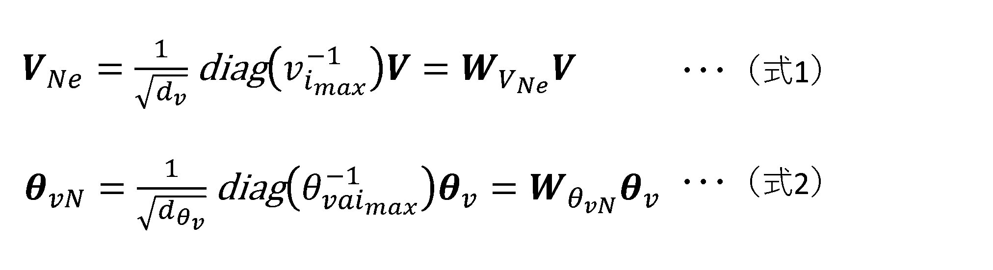
なお、速度ベクトルVにおいて、[xv,yv,zv]は、並進ベクトルvlと表すことができ、[ωx,ωy,ωz]は、角速度ベクトルωと表すことができる。並進ベクトルvlと角速度ベクトルωとは互いに単位系で異なる。このため、以下の式3のように、速度ベクトルVは、並進ベクトルvlの最大ノルム||vl||maxと角速度ベクトルωの最大ノルム||ωl||maxとを用いて、速度ベクトルVNに正規化されてもよい。本例では、補正係数dvは、1≦dv≦2を満たす。I3は、3行×3列の単位行列である。

そして、正規化速度ベクトルVNe又はVNと、正規化速度ベクトルθvNとを用いて、ヤコビ行列Jを正規化できる。ヤコビ行列Jは、V=Jθvの関係を満たす。上記関係と式2と式3とを用いると、以下の式4に示すように、ヤコビ行列Jをヤコビ行列JNに正規化できる。正規化ヤコビ行列JNは、WvNJWθvN
-1である。以下において、正規化速度ベクトルを、正規化速度指令値、正規化速度指令、速度指令値又は速度指令と表現する場合もある。

エンドエフェクタ12の速度ベクトルVの上限値が適切に設定されている場合、正規化速度ベクトルVNのノルム||VN||が、||VN||≦1を満たすので、各関節の関節速度の最大値が適切に設定されていれば、正規化速度ベクトルθvNのノルム||θvN||が、||θvN||≦1を満たし、ロボットアーム11に、ユーザインタフェース30から出力されるエンドエフェクタ12の速度指令値に従って動作させることができる。
よって、情報処理装置100は、ステップS6において、式1又は式3に従って、エンドエフェクタ12の速度指令値Vを正規化して、正規化速度ベクトルVNe又はVNを算出する。さらに、情報処理装置100は、正規化速度ベクトルVNe又はVNとヤコビ行列Jとを、JN=WvNJWθvN
-1のような関係に適用して、正規化ヤコビ行列JNを算出しメモリMに記憶する。
次いで、ステップS7において、以下の式5に示すように、情報処理装置100は、正規化ヤコビ行列JNを特異値分解して、3つの行列Uv、Σ及びVθを含む行列集合M1を生成する。行列Uvは、正規直交系であり、行列Uvの列ベクトルuvi(i=1,・・・,n)は、特異値分解で定義されるエンドエフェクタ12の速度空間の基底ベクトルである。行列Vθは、正規直交系であり、行列Vθの列ベクトルである転置行列Vθ
Tの行ベクトルvθi(i=1,・・・,n)は、特異値分解で定義される複数の関節JTの速度空間の基底ベクトルである。行列Σは、対角行列であり、その対角成分が特異値σi(i=1,・・・,n)である。行列Σにおいて、対角成分は、σ1>σ2>・・・>σnと降順に並ぶ。列ベクトルuviについての「n」は、エンドエフェクタ12の速度の次元数であり、行ベクトルvθiについての「n」は、複数の関節JTの速度の次元数である。ロボットアーム11の姿勢が特異点に近くなるほど、最小特異値σnが小さくなる。行列集合M1は、第2ヤコビ行列の一例である。行列Vθ
Tは第1行列の一例であり、行列Uvは第2行列の一例であり、行列Σは、第1特異行列の一例である。ベクトルvθiは第1基底ベクトルの一例であり、ベクトルuviは第2基底ベクトルの一例である。

なお、ロボットアーム11の姿勢が特異点に該当しない状態である非特異状態の場合、正規化ヤコビ行列JNの逆行列、つまり、行列集合M1の逆行列は、以下の式6のように表される。行列集合M1の逆行列は、第2逆ヤコビ行列の一例である。行列Vθは第1変換行列の一例であり、行列UV
Tは、第2変換行列の一例であり、行列Σ-1は、第1変換特異行列の一例である。
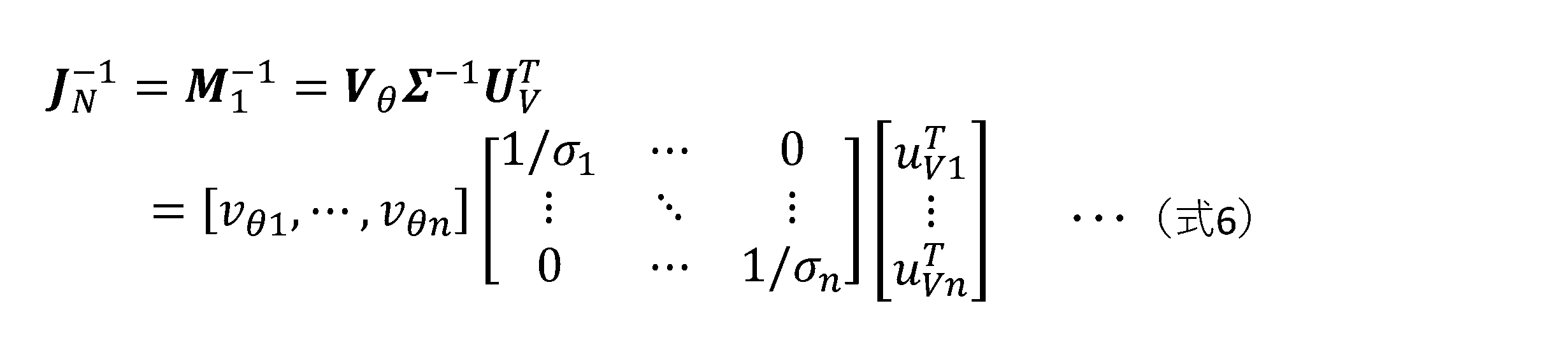
エンドエフェクタ12の速度指令値Vは、式1を用いて、速度ベクトルVNに正規化できる。正規化速度ベクトルVNは、そのノルム||VN||と、正規化速度ベクトルVNの単位ベクトルuNとを用いて、以下の式7に示すように表現することができる。

速度指令値Vに従ってエンドエフェクタ12を移動するための関節JT1からJT6の速度ベクトルθvを正規化して得られる速度ベクトルθvNは、式6及び式7を用いて、以下の式8のように表される。

ロボットアーム11の姿勢が特異点に近づくと、正規化速度ベクトルθvNのノルム||θvN||は、||θvN||≦1を満たさない可能性がある。このため、式8の正規化速度ベクトルθvNを以下の式9のように、正規化速度ベクトルθvN1に変更すると、||θvN1||≦1が保証される。よって、ロボットアーム11の動作の指令値を生成するために、正規化速度ベクトルθvNの代わりに、正規化速度ベクトルθvN1を用いることができ、これにより、式8に従った分解速度制御が、式9に従った分解速度制御に変更され得る。

次いで、ステップS8において、情報処理装置100は、正規化指令速度VNのノルム||VN||が閾値εV以上であるか否かを判定する。情報処理装置100は、ノルム||VN||が閾値εV以上である場合(ステップS8でYes)にステップS9へ進み、ノルム||VN||が閾値εV未満である場合(ステップS8でNo)にステップS10へ進む。ノルム||VN||が閾値εV未満であるように、正規化速度ベクトルVNの大きさが小さ過ぎる場合、式7に基づく、単位ベクトルuNを算出する正規化計算であるuN=VN/||VN||が数値的に不安定になる。このため、情報処理装置100は、ノルム||VN||が閾値εV未満となるような速度指令値を受け付けずに0とみなす。
ステップS10では、情報処理装置100は、エンドエフェクタ12の速度指令値Vを0に設定する、状態0に従った分解速度制御を行う。図9に示すように、ステップS10は、ステップS1001からS1008を含み、その詳細は後述する。
また、ステップS9において、情報処理装置100は、ロボットアーム11の姿勢が特異点又は特異点の近傍の領域にあるか否かを判定する。情報処理装置100は、ロボットアーム11の姿勢が特異点又は特異点の近傍の領域にある場合(ステップS9でYes)にステップS11へ進み、ロボットアーム11の姿勢が特異点にも特異点の近傍の領域にもない場合(ステップS9でNo)にステップS12へ進む。
ロボットアーム11の姿勢が特異点に近づくに従って、式8の1/σnは大きくなり、やがては、ヤコビ行列の逆行列の数値計算が不可能になる。このため、ステップS9では、情報処理装置100は、最小の特異値σnと閾値εσnとの比較結果に基づく処理を行う。情報処理装置100は、σn<εσnである場合、ロボットアーム11の姿勢が特異点又は特異点の近傍の領域にあると決定し、σn≧εσnである場合、ロボットアーム11の姿勢が特異点にも特異点の近傍の領域にもないと決定する。閾値εσnは、第1閾値の一例である。
閾値εσnは、最小特異値σnに対して0以外の値で設定される閾値である。例えば、閾値εσnは、式8のように表される正規化速度ベクトルθvNのノルム||θvN||を、||θvN||>1とするような最小特異値σnの経験則に基づき設定されてもよい。
閾値εσnは、κ=σ1/σnで定義される条件数κに基づき設定されてもよい。例えば、条件数κの逆数1/κ(=σn/σ1)に閾値1/κ0を設定することができる。閾値εσnは、1/κ0を基準に設定でき、例えば、εσn=σ1/κ0に設定できる。
ステップS12では、情報処理装置100は、通常状態の分解速度制御である状態NS(Non Singular)に従った分解速度制御を行う。図10に示すように、ステップS12は、ステップS1201からS1209を含み、その詳細は後述する。
ステップS11において、情報処理装置100は、式8に基づき、エンドエフェクタ12の正規化指令速度ベクトルVNのうちのエンドエフェクタ12の速度空間の基底ベクトルuvnの方向の寄与度wnを、以下の式10に示すように算出する。ベクトルuNは、正規化速度ベクトルVNの単位ベクトルである。寄与度wnがとり得る範囲は、0≦wn≦1である。寄与度wnは、エンドエフェクタ12の指令速度の方向が、特異点にある状態のロボットアーム11によって実現できないエンドエフェクタ12の速度の方向成分に寄与する程度を示す。寄与度wnが1に近づく程、寄与する程度が大きい。

次いで、ステップS13において、情報処理装置100は、寄与度wnが閾値εwn以上であるか否かを判定する。情報処理装置100は、寄与度wnが閾値εwn以上である場合(ステップS13でYes)にステップS14に進み、寄与度wnが閾値εwn未満である場合(ステップS13でNo)にステップS15に進む。閾値εwnは、0<εwn<1の範囲で設定される。閾値εwnは、第3閾値の一例である。
ステップS14では、情報処理装置100は、状態SC(Singularity Consistent)に従った分解速度制御を行う。状態SCは、特異点又は特異点の近傍の領域での寄与度が閾値以上である状態の分解速度制御である。図11に示すように、ステップS14は、ステップS1401からS1429を含み、その詳細は後述する。
ステップS15では、情報処理装置100は、状態P(Perpendicular)に従った分解速度制御を行う。状態Pは、特異点又は特異点の近傍の領域での寄与度が閾値よりも小さい状態の分解速度制御である。図12に示すように、ステップS15は、ステップS1501からS1511を含み、その詳細は後述する。
図9を使用して、状態0に関するステップS10の詳細を説明する。まず、ステップS1001では、情報処理装置100は、エンドエフェクタ12の速度指令値Vを0に設定し、関節JT1からJT6の動作を停止する速度指令値を決定し、関節JT1からJT6のモータM1からM6の回転を停止する指令値を電力制御回路200に出力する。
次いで、ステップS1002では、電力制御回路200は、モータM1からM6の回転を停止することで、ロボットアーム11の動作を停止する。
次いで、ステップS1003では、情報処理装置100は、ステップS3と同様に、ユーザインタフェース30から受信する信号から、エンドエフェクタ12の新たな速度指令値を取得する。
次いで、ステップS1004では、情報処理装置100は、ステップS4と同様に、ロボット10の新たなフィードバック情報を取得する。
次いで、ステップS1005では、情報処理装置100は、ステップS5と同様に、新たな速度指令値及び新たなフィードバック情報を用いて、ヤコビ行列Jを算出する。
次いで、ステップS1006では、情報処理装置100は、ステップS6と同様に、ヤコビ行列Jを正規化する。
次いで、ステップS1007では、情報処理装置100は、ステップS7と同様に、正規化ヤコビ行列JNを特異値分解する。
次いで、ステップS1008では、情報処理装置100は、ステップS8と同様に、正規化指令速度VNのノルム||VN||が閾値εV以上であるか否かを判定する。情報処理装置100は、ノルム||VN||が閾値εV以上である場合(ステップS1008でYes)にステップS9へ進み、ノルム||VN||が閾値εV未満である場合(ステップS1008でNo)にステップS1001に戻り、以降の処理を繰り返す。
図10を使用して、状態NSに関するステップS12の詳細を説明する。まず、ステップS1201では、情報処理装置100は、状態NSの分解速度制御に従った処理により、関節JT1からJT6の速度指令値を生成する。情報処理装置100は、エンドエフェクタ12の速度指令値Vを、式3に従って速度ベクトルVNに正規化する。さらに、情報処理装置100は、正規化速度ベクトルVNを式9に適用して、関節JT1からJT6の正規化速度ベクトルθvN1を算出する。情報処理装置100は、正規化速度ベクトルθvN1を非正規形に戻すことで、関節JT1からJT6の速度指令値θvを算出する。これにより、関節JT1からJT6の速度が関節JT1からJT6に設定される上限速度以下に保証される。
なお、情報処理装置100は、θv=J-1Vの関係式に従って、エンドエフェクタ12の速度指令値Vを、ヤコビ行列Jの逆行列に適用することで、関節JT1からJT6の速度指令値θvを生成してもよい。
次いで、ステップS1202では、情報処理装置100は、フィードバック情報に含まれる回転センサEの検出結果から得られる関節JT1からJT6の速度と速度指令値θvとの差分と、フィードバック情報に含まれるモータM1からM6の電流値とを用いて、速度指令値θvに従って関節JT1からJT6に動作させるためにモータM1からM6に印加する電流値を決定する。情報処理装置100は、決定した電流値の指令を電力制御回路200に出力し、電力制御回路200は、当該電流値に従ってモータM1からM6を駆動し、ロボットアーム11に動作させる。
次いで、ステップS1203では、情報処理装置100は、ステップS1003と同様に、ユーザインタフェース30から受信する信号から、エンドエフェクタ12の新たな速度指令値を取得する。
次いで、情報処理装置100は、ステップS1204からS1207において、新たな速度指令値を用いて、ステップ1004からS1007と同様の処理を行う。
次いで、ステップS1208では、情報処理装置100は、ステップS1008と同様に、正規化指令速度VNのノルム||VN||が閾値εV以上であるか否かを判定する。情報処理装置100は、ノルム||VN||が閾値εV以上である場合(ステップS1208でYes)にステップS1209へ進み、ノルム||VN||が閾値εV未満である場合(ステップS1208でNo)にステップS10のステップS1001に進む。
次いで、ステップS1209では、情報処理装置100は、ステップS9と同様に、ロボットアーム11の姿勢が特異点又は特異点の近傍の領域にあるか否かを判定する。情報処理装置100は、ロボットアーム11の姿勢が特異点又は特異点の近傍の領域にある場合(ステップS1209でYes)にステップS11へ進み、ロボットアーム11の姿勢が特異点にも特異点の近傍の領域にもない場合(ステップS1209でNo)にステップS1201へ戻り、以降の処理を繰り返す。
図11を使用して、状態SCに関するステップS14の詳細を説明する。まず、ステップS1401において、情報処理装置100は、状態SCの分解速度制御に従った処理を行う。情報処理装置100は、式6に示される正規化ヤコビ行列JNの逆行列JN
-1を変換し、以下の式11に示すような新たな行列JεNを算出する。行列JεNも正規化された行列である。具体的には、情報処理装置100は、逆行列JN
-1に含まれる特異値要素1/σ1,・・・,1/σn間の比率を維持するように、式6の逆行列JN
-1内の行列Σ-1のすべての要素をσn/εσn倍する。要素1/σi(i=1,・・・,n)は、σn/σiεσnに変更される。さらに、σn/σiεσnを1/σi
’と表す。行列JεNは、第3逆ヤコビ行列の一例であり、行列JεNの逆行列は、第3ヤコビ行列の一例である。逆行列JN
-1から行列JεNへの変換は、第1変換の一例であり、σn/εσnは、第1比率の一例である。

ここで、例えば、情報処理装置100は、式11に基づき、式9と同様に、以下の式12に示すような分解速度制御に従った処理を行うことができる。情報処理装置100は、特異点又はその近傍領域において、エンドエフェクタ12の速度指令値に対応する正規化速度ベクトルVNに応じて、関節JT1からJT6の速度指令値に対応する正規化速度ベクトルθvNAを生成できる。そして、正規化速度ベクトルθvNAのノルム||θvNA||は、||θvNA||≦1に保証される。

また、ロボットアーム11の姿勢が特異点に該当する状態である特異状態の場合、式12の行列JεNは、以下の式13に示すような行列となる。これは、ロボットアーム11に特異点におけるセルフモーションを生じさせる零空間に相当する。

式12に従った分解速度制御において、ノルム||JεNuN||が過小になると、正規化が数値計算上不安定になり得る。これは、ロボットアーム11が特異状態に近づくことで、式12の1/σi
’(i=1,・・・,n-1)が0に近づき、寄与度wnが0に近づく状態に相当する。例えば、特異状態において寄与度wnが0である場合、ノルム||JεNuN||は0になる。
そこで、ステップS1402において、情報処理装置100は、正規化行列JεNとエンドエフェクタ12の正規化指令速度ベクトルVNとのノルム||JεNuN||が閾値κθ以上であるか否かを判定する。閾値κθは、エンドエフェクタ12の正規化速度ベクトルVNの単位ベクトルuNと正規化行列JεNとの積のノルムに設定される閾値である。情報処理装置100は、ノルム||JεNuN||が閾値κθ以上である場合(ステップS1402でYes)、ステップS1410へ進み、ノルム||JεNuN||が閾値κθ未満である場合(ステップS1402でNo)、ステップS1420へ進む。閾値κθは、第2閾値の一例であり、ノルム||JεNuN||は、第2ノルムの一例である。
ステップS1410において、情報処理装置100は、状態SC-1の分解速度制御に従った処理を行う。情報処理装置100は、行列JεNを用いる式12に示される分解速度制御に従って、関節JT1からJT6の速度指令値を生成する。情報処理装置100は、ステップS1201と同様に、エンドエフェクタ12の速度指令値Vを速度ベクトルVNに正規化する。さらに、情報処理装置100は、正規化速度ベクトルVNを式12に適用して、関節JT1からJT6の正規化速度ベクトルθvNAを算出する。式11の行列JεNにおける対角要素である特異値要素は、ロボットアーム11が特異状態に近づいても発散しない。そして、速度ベクトルθvNAのノルム||θvNA||は、||θvNA||≦1を満たす。
さらに、式11の行列JεNでは、対角要素である特異値要素間の比率が、正規化ヤコビ行列JNの逆行列JN
-1に含まれる特異値要素間の比率を維持する。このため、正規化速度ベクトルθvNAに従って関節JT1からJT6が動作することによってロボットアーム11がエンドエフェクタ12を移動する方向は、状態NSの分解速度制御のステップS1201で算出された正規化速度ベクトルθvNに従って関節JT1からJT6が動作することによってロボットアーム11がエンドエフェクタ12を移動する方向から変化しない。よって、ロボットアーム11は、特異点の近傍でエンドエフェクタ12を目標とする軌道から逸脱させることなく、特異点で関節速度が上限値を超過するエラーにより急停止することなく、エンドエフェクタ12の指令速度の方向にエンドエフェクタ12を移動させることができる。
次いで、ステップS1411において、情報処理装置100は、ステップS1202と同様に、速度指令値に従って関節JT1からJT6に動作させるためのモータM1からM6の印加電流値を決定する。情報処理装置100は、決定した電流値の指令を電力制御回路200に出力し、電力制御回路200は、当該電流値に従ってモータM1からM6を駆動し、ロボットアーム11に動作させる。
次いで、ステップS1412からS1416では、情報処理装置100は、ステップS1203からS1207と同様に、ユーザインタフェース30から受信する信号から、エンドエフェクタ12の新たな速度指令値を取得し、正規化ヤコビ行列JNを算出して特異値分解する。
次いで、ステップS1417では、情報処理装置100は、ステップS1208と同様に、正規化指令速度VNのノルム||VN||が閾値εV以上であるか否かを判定する。情報処理装置100は、ノルム||VN||が閾値εV以上である場合(ステップS1417でYes)にステップS1418へ進み、ノルム||VN||が閾値εV未満である場合(ステップS1417でNo)にステップS10のステップS1001に進む。
ステップS1418において、情報処理装置100は、ステップS1401と同様に、ステップS1412からS1416で算出した正規化ヤコビ行列JNの逆行列JN
-1を変換し、新たな行列JεNを算出する。
次いで、ステップS1419では、情報処理装置100は、正規化行列JεNとエンドエフェクタ12の正規化指令速度ベクトルVNとのノルム||JεNuN||が閾値κθ未満であるか否かを判定する。情報処理装置100は、ノルム||JεNuN||が閾値κθ未満である場合(ステップS1419でYes)、ステップS1402に戻り、ノルム||JεNuN||が閾値κθ以上である場合(ステップS1419でNo)、ステップS1410に戻り、以降の処理を繰り返す。
ステップS1420において、情報処理装置100は、状態SC-2の分解速度制御に従った処理を行う。情報処理装置100は、式12の代わりに、以下の式14に示される分解速度制御に従って処理を行う。式14では、ノルム||JεNuN||が、閾値κθに置き換えられることで、定数に固定される。これにより、ノルム||JεNuN||が過小になった場合の関節速度の数値計算上の不安定化が抑えられる。情報処理装置100は、行列JεNを用い且つノルム||JεNuN||を固定した式14に示される分解速度制御に従って、関節JT1からJT6の速度指令値を生成する。

情報処理装置100は、ステップS1410と同様に、エンドエフェクタ12の速度指令値Vの正規化速度ベクトルVNを式14に適用して、関節JT1からJT6の正規化速度ベクトルθvNBを算出する。正規化速度ベクトルθvNBの各要素は、ノルム||JεNuN||の大きさに応じた速度を示す。正規化速度ベクトルθvNBの各要素は、ノルム||JεNuN||が小さくなるに従って、関節JT1からJT6の速度を連続的に徐々に減少する。
そして、正規化速度ベクトルθvNBのノルム||θvNB||は、||θvNB||≦1を満たす。さらに、ステップS1410と同様に、正規化速度ベクトルθvNBに従って関節JT1からJT6が動作することによってロボットアーム11がエンドエフェクタ12を移動する方向は、状態NSの分解速度制御のステップS1201で算出された正規化速度ベクトルθvNに従ったエンドエフェクタ12の移動方向から変化しない。よって、ロボットアーム11は、特異点の近傍でエンドエフェクタ12を目標とする軌道から逸脱させることなく、特異点で関節速度が上限値を超過するエラーにより急停止することなく、エンドエフェクタ12の指令速度の方向にエンドエフェクタ12を移動させることができる。
次いで、ステップS1421において、情報処理装置100は、ステップS1411と同様に、速度指令値に従って関節JT1からJT6に動作させるためのモータM1からM6の印加電流値を決定する。情報処理装置100は、決定した電流値の指令を電力制御回路200に出力し、電力制御回路200は、当該電流値に従ってモータM1からM6を駆動し、ロボットアーム11に動作させる。
次いで、ステップS1422からS1426では、情報処理装置100は、ステップS1412からS1416と同様に、ユーザインタフェース30から受信する信号から、エンドエフェクタ12の新たな速度指令値を取得し、正規化ヤコビ行列JNを算出して特異値分解する。
次いで、ステップS1427では、情報処理装置100は、ステップS1417と同様に、正規化指令速度VNのノルム||VN||が閾値εV以上である場合(ステップS1427でYes)にステップS1428へ進み、ノルム||VN||が閾値εV未満である場合(ステップS1427でNo)にステップS10のステップS1001に進む。
ステップS1428において、情報処理装置100は、ステップS1418と同様に、ステップS1422からS1426で算出した正規化ヤコビ行列JNの逆行列JN
-1を変換し、新たな行列JεNを算出する。
次いで、ステップS1429では、情報処理装置100は、正規化行列JεNとエンドエフェクタ12の正規化指令速度ベクトルVNとのノルム||JεNuN||が閾値κθ以上であるか否かを判定する。情報処理装置100は、ノルム||JεNuN||が閾値κθ以上である場合(ステップS1429でYes)、ステップS1402に戻り、ノルム||JεNuN||が閾値κθ未満である場合(ステップS1429でNo)、ステップS1420に戻り、以降の処理を繰り返す。
図12を使用して、状態Pに関するステップS15の詳細を説明する。まず、ステップS1501において、情報処理装置100は、ステップS1401の式11の正規化行列JεNを変換した行列であり且つ以下の式15に示される新たな行列JεNAを生成する。行列JεNAも正規化された行列である。上記変換では、正規化行列JεNの要素1/εσnが、0に置き換えられる。行列JεNAは、第4逆ヤコビ行列の一例である。

寄与度wnが閾値εwn未満であり十分に小さい状態では、エンドエフェクタ12の指令速度の方向成分の中で、特異状態により生成できないエンドエフェクタ12の速度の方向成分は、非常に小さい。このような速度の方向成分は、特異値要素1/εσnに関連する速度成分である。例えば、ステップS1401の式11の正規化行列JεNを用いて正規化速度ベクトルθvNAを生成した場合、正規化速度ベクトルθvNAは、エンドエフェクタ12の指令速度の方向に従ったエンドエフェクタ12の移動を実現できるが、エンドエフェクタ12の速度の大きさが非常に小さい状態で実現することになる。
一方、寄与度wnが0である場合、エンドエフェクタ12の指令速度の方向成分の中で、特異状態により生成できないエンドエフェクタ12の速度の方向成分は、存在しないことになる。つまり、特異値要素1/εσnの方向の指令速度が、存在しないことになる。このため、上記変換は、寄与度wnが十分に小さい状態において、特異状態により生成できないエンドエフェクタ12の速度の方向成分に関連する要素1/εσnを0とすることで、このような方向成分を切り捨て、それにより、エンドエフェクタ12の指令速度をそのまま実現できるようにするものである。
式15により、特異値要素1/εσnの方向の指令速度がなかったものとされる。これは、エンドエフェクタ12の指令速度に対応する正規化速度ベクトルVNを、以下の式16に示すような新たな速度ベクトルVNAに変更することに相当する。

次いで、ステップS1502において、情報処理装置100は、正規化行列JεNAを使用した以下の式17に示される分解速度制御に従って、関節JT1からJT6の速度指令値を生成する。情報処理装置100は、ステップS1201と同様に、エンドエフェクタ12の速度指令値Vの正規化速度ベクトルVNを式17に適用して、関節JT1からJT6の正規化速度ベクトルθvNCを算出する。

正規化速度ベクトルθvNCは、エンドエフェクタ12の指令速度(手先速度)の中で特異値要素1/εσnの方向の速度成分をないものとみなことによって手先速度の次元数を1つ減少させ、結果的に次元が落とされて特異状態でなくなったロボットアーム11に対する速度指令値に相当する。このため、正規化速度ベクトルθvNCは、ロボットアーム11が特異状態であっても、エンドエフェクタ12の指令速度を、ロボットアーム11に近似的に実現させることができる。さらに、正規化速度ベクトルθvNCのノルム||θvNC||は、||θvNC||≦1を満たす。よって、ロボットアーム11は、特異点の近傍でエンドエフェクタ12を目標とする軌道から逸脱させることなく、特異点で関節速度が上限値を超過するエラーにより急停止することなく、エンドエフェクタ12の指令速度の方向にエンドエフェクタ12を移動させることができる。情報処理装置100は、ステップS1502の後、ステップS1503に進む。
ここで、操作者によるユーザインタフェース30の操作によりエンドエフェクタ12の指令速度の方向が変わり、寄与度wnが閾値εwn以上の状態から減少して閾値εwn未満の状態に移行する場合がある。寄与度wnが閾値εwn以上の状態では、例えば、ロボットアーム11は、ステップS1401の式12の正規化速度ベクトルθvNA又はステップS1420の式14の正規化速度ベクトルθvNBに従った速度でエンドエフェクタ12を移動する。この際、寄与度wnが減少するに従って、エンドエフェクタ12の速度が低下する。さらに、寄与度wnが閾値εwn未満になると、ロボットアーム11は、式17の正規化速度ベクトルθvNCに従った速度でエンドエフェクタ12を移動する。
上述したように、正規化速度ベクトルθvNCは、速度の次元数が1つ減少し且つ特異状態にないロボットアーム11に対する速度指令値に相当し、エンドエフェクタ12の指令速度を近似的に実現できる。このため、状態SCから寄与度wnが閾値εwn未満になったタイミングで状態Pに遷移し、ロボットアーム11のエンドエフェクタ12がある速度で突然に移動する可能性がある。しかし、図10から図12から分かるように、状態SCから状態Pに遷移するには、一旦状態0に遷移するか、状態NSに遷移することが必要であり、そのように突然にエンドエフェクタ12が動き始めることがないようになっている。さらに、情報処理装置100は、操作者に速度の切り替わりを報知して、ユーザインタフェース30の操作の調整を促すことができる。
ステップS1503において、情報処理装置100は、ステップS1202と同様に、速度指令値に従って関節JT1からJT6に動作させるためのモータM1からM6の印加電流値を決定する。情報処理装置100は、決定した電流値の指令を電力制御回路200に出力し、電力制御回路200は、当該電流値に従ってモータM1からM6を駆動し、ロボットアーム11に動作させる。
次いで、ステップS1504からS1508では、情報処理装置100は、ステップS1203からS1207と同様に、ユーザインタフェース30から受信する信号から、エンドエフェクタ12の新たな速度指令値を取得し、正規化ヤコビ行列JNを算出して特異値分解する。
次いで、ステップS1509では、情報処理装置100は、ステップS1208と同様に、正規化指令速度VNのノルム||VN||が閾値εV以上である場合(ステップS1509でYes)にステップS1510へ進み、ノルム||VN||が閾値εV未満である場合(ステップS1509でNo)にステップS10のステップS1001に進む。
ステップS1510において、情報処理装置100は、ステップS1504からS1508で取得したエンドエフェクタ12の速度指令値Vについて、ステップS11と同様に、エンドエフェクタ12の正規化指令速度ベクトルVNのうちの最小特異値σnに関連する基底ベクトルuvnの方向の寄与度wnを算出する。
次いで、ステップS1511において、情報処理装置100は、ステップS1504からS1508での特異値分解により得られた最小特異値σnが閾値εσn以上であり且つ寄与度wnが閾値εwn未満であるという条件が満たされるか否かを判定する。情報処理装置100は、当該条件が満たされる場合(ステップS1511でYes)の場合にステップS12に進み、当該条件が満たされない場合(ステップS1511でNo)の場合にステップS1501に戻り、以降の処理を繰り返す。上記条件が満たされる場合、エンドエフェクタ12の速度指令値Vの中で最小特異値σnに関連する方向の速度成分が小さく、最小特異値σnが特異状態ではない。このため、ロボットアーム11は、状態Pから抜け出すことができる。
ステップS3からS15により、情報処理装置100は、状態0、状態NS、状態SC及び状態Pの間で分解速度制御方法を遷移させつつ、特異点の近傍でエンドエフェクタ12を目標とする軌道から逸脱させることなく、特異点で関節速度が上限値を超過するエラーにより急停止することなく且つエンドエフェクタ12の指令速度の方向にエンドエフェクタ12を移動させるように、ロボットアーム11を制御できる。
状態0は、エンドエフェクタ12の指令速度が閾値未満であり、エンドエフェクタ12の速度指令値を0とみなしてロボットアーム11を停止させた状態である。状態NSは、通常の分解速度制御で、関節JTの速度指令値を生成可能な状態である。状態SCは、ロボットアーム11が特異状態に近い又は特異状態にある状態に対応した分解速度制御で、関節JTの速度指令値を生成可能な状態である。状態Pは、エンドエフェクタ12の指令速度が特異値σnに対応する指令方向uvnの成分を含まないようにした状態に対応した分解速度制御で、関節JTの速度指令値を生成可能な状態である。
情報処理装置100は、状態NSと状態SCとの間の分解速度制御の遷移を、最小特異値σnと閾値εσnとの関係がσn≧εσnであるかσn<εσnであるかに応じて決定する。例えば、σn<εσnであり且つ寄与度wnがwn≧εwnを満たせば、情報処理装置100は、状態SCの分解速度制御への遷移を決定する。よって、状態NSと状態SCとの間の遷移の連続性が保たれる。さらに、情報処理装置100は、状態SCにおいて、ノルム||JεNuN||と閾値κθとの関係が、||JεNuN||≧κθであるか||JεNuN||<κθであるかに応じて、2つの状態間の分解速度制御の遷移を決定する。情報処理装置100は、2つの状態のいずれにおいても、ノルム||JεNuN||が閾値κθを下回らないようにして分解速度制御を行うため、2つの状態間の遷移の連続性が保たれる。
情報処理装置100は、状態NSと状態Pとの間の遷移を、寄与度wnと閾値εwnとの関係がwn≧εwnであるかwn<εwnであるかに応じて決定することができる。wn<εwnであり且つ最小特異値σnと閾値εσnとの関係がσn<εσnを満たす場合に、情報処理装置100は、状態NSから状態Pの分解速度制御へ遷移し、エンドエフェクタ12の指令速度から特異値σnに対応する指令方向uvnの成分を除去するが、閾値εwnを小さく設定することによって、2つの状態間の遷移の連続性が保たれる。
状態Pでは、エンドエフェクタ12の指令速度から指令方向uvnの成分が除去されるため、エンドエフェクタ12の指令速度における寄与度wnがwn≧εwnの関係を満たしても、ロボットアーム11に実際に指令されるエンドエフェクタ12の速度は、方向uvnの成分が除去されたものになる。このため、情報処理装置100は、wn<εwn且つσn≧εσnが満たされる場合に状態Pから状態NSの分解速度制御に遷移する。この場合、2つの状態間の遷移の連続性が保たれる。
情報処理装置100は、状態SCと状態Pとの間の直接の遷移は許さない。状態SCから状態Pに遷移するには、一旦エンドエフェクタ12の指令速度を0にして状態0に遷移させてロボットアーム11を一旦停止させ、その後寄与度wnがwn<εwnの関係を満たすようなエンドエフェクタ12の速度指令値をいきなり出すことで状態Pに遷移させることができる。なお、情報処理装置100は、一旦状態NSの分解速度制御に遷移した後に、状態Pの分解速度制御に遷移することもできる。
逆に状態Pから状態SCに遷移するには、一旦エンドエフェクタ12の指令速度を0にして状態0に遷移させてロボットアーム11を一旦停止させ、その後寄与度wnがwn≧εwnの関係を満たすようなエンドエフェクタ12の速度指令値を出すことで、状態SCに遷移できる。なお、情報処理装置100は、状態Pから一旦状態NSの分解速度制御に遷移した後に、状態SCの分解速度制御に遷移することもできる。
[エンドエフェクタ12の移動速度の上限の保証の検証]
ステップS1からS15では、情報処理装置100は、関節JTの速度指令値に対応する正規化速度ベクトルθvNのノルム||θvN||の大きさが||θvN||≦1を満たすように、正規化速度ベクトルθvNを処理する。しかしながら、ロボットアーム11の姿勢によっては、正規化速度ベクトルθvNを非正規形にした速度指令値によって実現されるエンドエフェクタ12の速度の大きさが、エンドエフェクタ12の指令速度の上限を超える可能性も考えられる。そこで、式9、式12、式14及び式17により得られる関節JTの正規化速度ベクトルについて、エンドエフェクタ12の移動速度の上限の保証を検証する。
ステップS1からS15では、情報処理装置100は、関節JTの速度指令値に対応する正規化速度ベクトルθvNのノルム||θvN||の大きさが||θvN||≦1を満たすように、正規化速度ベクトルθvNを処理する。しかしながら、ロボットアーム11の姿勢によっては、正規化速度ベクトルθvNを非正規形にした速度指令値によって実現されるエンドエフェクタ12の速度の大きさが、エンドエフェクタ12の指令速度の上限を超える可能性も考えられる。そこで、式9、式12、式14及び式17により得られる関節JTの正規化速度ベクトルについて、エンドエフェクタ12の移動速度の上限の保証を検証する。
まず、状態SCにおいて、式9により得られる正規化速度ベクトルθvN1の場合、正規化速度ベクトルθvN1により実現されるエンドエフェクタ12の正規化速度ベクトルVNRは、以下の式18のように得られる。さらに、以下の式19に示すように、正規化速度ベクトルVNRのノルム||VNR||は、エンドエフェクタ12の正規化指令速度ベクトルVNのノルム||VN||よりも大きくなる可能性がある。

この場合、以下の式20によって、正規化速度ベクトルθvN1を補正することができる。ノルム||VNR||は、第1ノルムの一例であり、補正された正規化速度ベクトルθvN1は、補正動作指令値の一例である。

なお、式9から、以下の式21が得られ、式21から以下の式22が得られる。さらに、式22と式9とを式20に適用することにより、以下の式23が得られる。

よって、式20により補正された正規化速度ベクトルθvN1は、エンドエフェクタ12の正規化指令速度ベクトルVNに対して通常の分解速度制御を適用して得られる関節JTの正規化速度ベクトルに相当する。よって、ノルム||VNR||がノルム||VN||以下であることが確認できる。
次に、状態SCにおいて、式12により得られる正規化速度ベクトルθvNAの場合、正規化速度ベクトルθvNAにより実現されるエンドエフェクタ12の正規化速度ベクトルVNRAは、以下の式24のように得られる。さらに、以下の式25に示すように、正規化速度ベクトルVNRAのノルム||VNRA||は、エンドエフェクタ12の正規化指令速度ベクトルVNのノルム||VN||よりも大きくなる可能性がある。

この場合、以下の式26のように、正規化速度ベクトルθvNAを補正することができる。ノルム||VNRA||は、第1ノルムの一例であり、補正された正規化速度ベクトルθvNAは、補正動作指令値の一例である。

式12の正規化行列JεNは、正規化ヤコビ行列JNの逆行列JN
-1に対して、以下の式27の関係を満たす。そして、式26及び式27から、以下の式28が得られる。よって、式26により補正された正規化速度ベクトルθvNAは、エンドエフェクタ12の正規化指令速度ベクトルVNに対して通常の分解速度制御を適用して得られる関節JTの正規化速度ベクトルに相当する。よって、ノルム||VNRA||がノルム||VN||以下であることが確認できる。

次に、状態SCにおいて、式14により得られる正規化速度ベクトルθvNBの場合、正規化速度ベクトルθvNBにより実現されるエンドエフェクタ12の正規化速度ベクトルVNRBは、以下の式29のように得られる。さらに、以下の式30に示すように、正規化速度ベクトルVNRBのノルム||VNRB||は、エンドエフェクタ12の正規化指令速度ベクトルVNのノルム||VN||よりも大きくなる可能性がある。

この場合、以下の式31のように、正規化速度ベクトルθvNBを補正することができる。ノルム||VNRB||は、第1ノルムの一例であり、補正された正規化速度ベクトルθvNBは、補正動作指令値の一例である。

式14の正規化行列JεNは、正規化ヤコビ行列JNの逆行列JN
-1に対して、式27の関係を満たす。そして、式27及び式31から、以下の式32が得られる。よって、式31により補正された正規化速度ベクトルθvNBは、エンドエフェクタ12の正規化指令速度ベクトルVNに対して通常の分解速度制御を適用して得られる関節JTの正規化速度ベクトルに相当する。よって、ノルム||VNRB||がノルム||VN||以下であることが確認できる。

次に、状態Pにおいて、式17により得られる正規化速度ベクトルθvNCの場合、正規化速度ベクトルθvNCにより実現されるエンドエフェクタ12の正規化速度ベクトルVNRCは、以下の式33のように得られる。さらに、以下の式34に示すように、正規化速度ベクトルVNRCのノルム||VNRC||は、エンドエフェクタ12の正規化指令速度ベクトルVNのノルム||VN||よりも大きくなる可能性がある。

この場合、以下の式35のように、正規化速度ベクトルθvNCを補正することができる。ノルム||VNRC||は、第1ノルムの一例であり、補正された正規化速度ベクトルθvNCは、補正動作指令値の一例である。

そして、式16及び式17と、式27とから、以下の式36が得られる。さらに、ノルム||JNθvNC||が、以下の式37のように得られる。

よって、式17及び式37を式35に代入して、以下の式38が得られる。

式38において、正規化行列J’
εNAは、通常の正規化ヤコビ行列JNの逆行列JN
-1において、最小特異値σnの要素1/σnを0とした、逆行列JN
-1の疑似逆行列である。正規化行列J’
εNAは、正規化行列JεNAに類似する。式38により補正された関節JTの正規化速度ベクトルθvNCは、このような疑似逆行列による分解速度制御を適用して得られる関節JTの正規化速度ベクトルに相当する。
正規化行列J’
εNAが適用される状態Pは、寄与度wnが閾値εwn未満である場合に適用されるため、ノルム||VNA||はノルム||VN||に漸近的に等しい。よって、||VN||/||VNA||の影響は無視できる。
疑似逆行列J’
εNAによる解は、エンドエフェクタ12の正規化指令速度ベクトルVNをなるべく実現するものの中で最もノルムの小さいものとなるため、式38によって得られる関節JTの正規化速度ベクトルθvNCによって実現されるエンドエフェクタ12の速度のノルム||VNRC||の大きさが、エンドエフェクタ12の正規化指令速度ベクトルVNのノルム||VN||の大きさを上回ることがない。
上述より、状態SC及び状態Pのいずれのケースにおいても、情報処理装置100によって出力される関節JT1からJT6の速度指令値によって実現されるエンドエフェクタ12の速度の大きさは、エンドエフェクタ12の指令速度の大きさを超えないことが確認できる。
[特異状態でのセルフモーションに対する処理]
ヤコビ行列Jにおいて、式5に示されるような最小特異値σnが0になる場合がある。このような場合、ロボットアーム11は、完全な特異状態になる。このときの正規化ヤコビ行列JNは、以下の式39のように示される。
ヤコビ行列Jにおいて、式5に示されるような最小特異値σnが0になる場合がある。このような場合、ロボットアーム11は、完全な特異状態になる。このときの正規化ヤコビ行列JNは、以下の式39のように示される。
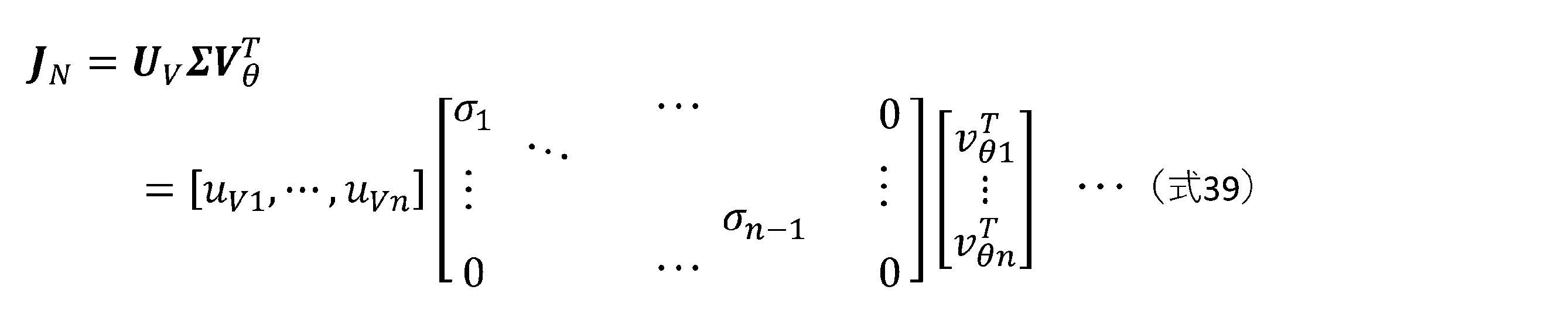
関節JTの速度空間の基底ベクトルvθnは、特異状態においては、関節JTの速度空間の中でエンドエフェクタ12の速度に影響しない零空間となる。このため、特異状態において、情報処理装置100は、エンドエフェクタ12の速度指令値Vに含まれるベクトルuVnの方向への速度指令値に対して、零空間の関節JTの速度指令値を出力する。このような関節JTの速度指令値に従ったロボットアーム11の動作には、セルフモーションが生じる。
ロボットアーム11は、図6及び図7に示す手首特異姿勢及び肩特異姿勢では、セルフモーションを継続可能である。ロボットアーム11は、図5に示す肘特異姿勢では、セルフモーションによって特異点から抜け出してしまう場合がある。肘特異姿勢の場合、ベクトルuVnの方向へのエンドエフェクタ12の速度指令値が与えられ続けると、ロボットアーム11は、図13Aから図13Bに示すように特異点に一旦到達し、その後、図13Cに示すようにセルフモーションにより特異点から抜け出してエンドエフェクタ12を目標方向と逆方向に移動する。その後、ロボットアーム11は、図13Cに示すように、再びエンドエフェクタ12を特異点に向かうように移動し、図13Bの状態に至る。その後、ロボットアーム11は、図13Aの状態から図13Cの状態を繰り返す。これにより、ロボットアーム11の振動現象が誘発される。図13Aから図13Cは、肘特異姿勢の場合のロボットアーム11のセルフモーションの一例を示す概念図である。
そこで、情報処理装置100は、このような振動現象を防ぐために、ロボットアーム11が図13Bの状態に至った時点で、ロボットアーム11の関節JT1からJT6の全ての動作を一旦停止する。例えば、振動現象を防ぐために、ロボットアーム11の関節JT1からJT6のうちセルフモーションに関連する関節JTのみ停止すると、ロボットアーム11は、エンドエフェクタ12の指令速度と異なる方向にエンドエフェクタ12を移動する可能性がある。情報処理装置100は、このような意図しない方向へのエンドエフェクタ12の移動を防ぐ。そして、情報処理装置100は、ユーザインタフェース30からの指令に従って、又は、自律的に、肘特異姿勢から逸脱するようにロボットアーム11を動作させる。なお、肘特異姿勢以外の特異状態において、情報処理装置100は、ロボットアーム11に一旦停止した後、特異状態から逸脱させてもよい。
また、情報処理装置100は、ヤコビ行列の計算に用いる幾何学的パラメータから、ロボットアーム11の特異状態の種類を識別することができる。エンドエフェクタ12の速度指令値Vと、関節JTの速度指令値θvと、ヤコビ行列Jとに関して、V=Jθvが成立する。この式をさらに時間微分して、以下の式40が得られる。

セルフモーション時において、上記の要素(dJ/dt)θvのノルム||(dJ/dt)θv||が零でない値を持つ場合、ロボットアーム11は肘特異点のようにセルフモーションによってその特異状態にとどまることができずに抜け出してしまうことになる。
ヤコビ行列Jにおいて、式5に示されるような最小特異値σnが閾値εσnに近くなり、ロボットアーム11の姿勢が特異点に近づくとき、最小特異値σnに対応する関節速度ベクトルである基底ベクトルvθnに着目することができる。関節速度ベクトルvθnは、特異値σn=0となる特異姿勢では、式39に示すようにセルフモーションに対応する関節速度を示す。
手首特異姿勢及び肩特異姿勢のようにセルフモーションを継続可能である特異点の場合、特異点の近傍においても、関節速度ベクトルvθnは、セルフモーションに近い速度を示す。それ故、ロボットアーム11によって移動されるエンドエフェクタ12の加速度は、十分に小さい。このため、最小特異値σn及び閾値εσnがσn<εσnを満たす特異点の近傍では、式41に示すように、要素(dJ/dt)vθnの絶対値|(dJ/dt)vθn|が閾値εa未満である条件を満たす場合、当該特異点は、セルフモーションを継続可能である特異点であるとすることができる。閾値εaは、エンドエフェクタ12の加速度の大きさの閾値である。dJ/dtは、第8ヤコビ行列の一例であり、(dJ/dt)vθnは、加速度ベクトルの一例であり、閾値εaは、第4閾値の一例である。

よって、情報処理装置100は、式41の条件が満たされる場合に、特異点を、ロボットアーム11のセルフモーションを継続可能である特異点に決定する。情報処理装置100は、式41の条件が満たされない場合に、特異点を、ロボットアーム11のセルフモーションを継続可能でない特異点に決定する。情報処理装置100は、式41の条件に加えて又は代わりに、ノルム||(dJ/dt)θv||が零でない値であることを条件として、特異点を、セルフモーションを継続可能である特異点に決定してもよい。情報処理装置100は、関節速度ベクトルvθnを用いることによって、現在のエンドエフェクタ12の速度指令値に関わらずに特異点の種別を判別できる。
情報処理装置100は、特異点を、セルフモーションを継続可能でない特異点に決定した場合、以下のようにロボットアーム11を停止する。情報処理装置100は、サンプリング周期毎に取得する情報を用いて、絶対値|(dJ/dt)vθn|を算出する。情報処理装置100は、ロボットアーム11が動作する過程において、絶対値|(dJ/dt)vθn|が最大となった時点で、ロボットアーム11を停止してもよい。例えば、情報処理装置100は、絶対値|(dJ/dt)vθn|の変動が増加から減少に転じたタイミングを、ロボットアーム11の停止のタイミングとしてもよい。限定されないが、肘特異姿勢の場合に、上記タイミングは、ロボットアーム11の停止のタイミングに特に適する。
さらに、情報処理装置100は、上記タイミングにおいて、エンドエフェクタ12の指令速度の方向が反転等により変化していないかを判別してもよい。これにより、絶対値|(dJ/dt)vθn|の増加から減少への変動が、エンドエフェクタ12の指令速度の方向の変化を起因とするか否かの判別が可能である。情報処理装置100は、式10において寄与度wnの算出に用いるエンドエフェクタ12の指令速度の単位ベクトルuと、セルフモーションを示す関節速度ベクトルvθnに対応するエンドエフェクタ12の速度ベクトルuvnとの内積uvn
Tuを、サンプリング周期毎に取得する情報を用いて算出しメモリMに記憶する。情報処理装置100は、絶対値|(dJ/dt)vθn|の変動が増加から減少に転じたタイミング又はその周辺において、内積uvn
Tuの符号が反転していない場合に、ロボットアーム11を停止する。
情報処理装置100は、停止したロボットアーム11を再び動かすタイミングを、内積uvn
Tuの符号に基づき決定してもよい。例えば、情報処理装置100は、ロボットアーム11の停止を決定したときの内積uvn
Tuの符号から、内積uvn
Tuの符号が反転したタイミングを、ロボットアーム11を再び動かすタイミングに決定してもよい。内積uvn
Tuがほぼ0の場合、エンドエフェクタ12の指令速度の、速度ベクトルuvnの方向の寄与度は無視できる。この場合、情報処理装置100が、ロボットアーム11を動かすと、ロボットアーム11の動作領域境界に沿ってエンドエフェクタ12を移動することになる。
[ロボットアームが複数の特異状態に陥るケース]
ロボットアーム11は、複数の特異状態に陥る場合がある。この場合、2つ以上の特異値σiが閾値εσn未満となる。式5の正規化ヤコビ行列JNにおいて、特異値σn及びσn-1が、閾値εσn未満となる例について、情報処理装置100の処理を説明する。本例では、特異値σn及びσn-1が、σn<σn-1<εσnの関係を満たす。特異値σnは、第1特異値の一例であり、特異値σn-1は、第2特異値の一例である。
ロボットアーム11は、複数の特異状態に陥る場合がある。この場合、2つ以上の特異値σiが閾値εσn未満となる。式5の正規化ヤコビ行列JNにおいて、特異値σn及びσn-1が、閾値εσn未満となる例について、情報処理装置100の処理を説明する。本例では、特異値σn及びσn-1が、σn<σn-1<εσnの関係を満たす。特異値σnは、第1特異値の一例であり、特異値σn-1は、第2特異値の一例である。
情報処理装置100は、寄与度wnが閾値εwn以上である状態SCについて、上述したステップS1401と同様に、式6に示される正規化ヤコビ行列JNの逆行列JN
-1内の行列Σ-1のすべての要素をσn/εσn倍して、以下の式42に示すような新たな行列JεNを算出する。しかしながら、特異値σn-1が閾値εσnを下回るため、特異値σn-1を含む要素1/σn-1については、情報処理装置100は、以下の式43のように数値計算の桁落ちを防ぐ処理をする。σn<σn-1であるため、要素1/σn-1
’は発散しない。情報処理装置100は、行列JεNに基づき分解速度制御を行う。寄与度wnは、第1寄与度の一例である。

寄与度wnが閾値εwn未満である状態Pにおいては、情報処理装置100は、特異値σn-1を最小特異値とみなす。情報処理装置100は、式6に示される正規化ヤコビ行列JNの逆行列JN
-1内の行列Σ-1のすべての要素を、σn-1/εσn倍する。要素1/σi(i=1,・・・,n-2)は、σn-1/σiεσnに変更される。さらに、σn-1/σiεσnを1/σi”と表す。さらに、情報処理装置100は、上述したステップS1501と同様に、特異値σnを含む要素を0に置き換える。これにより、情報処理装置100は、以下の式44に示すような新たな行列JεNAを算出する。情報処理装置100は、行列JεNAに基づき分解速度制御を行う。この場合、特異値σnに対応する空間を除いた補空間に対して処理が行われる。行列JεNAは、第5逆ヤコビ行列の一例であり、σn-1/εσnは、第2比率の一例である。

2つの特異値σn及びσn-1それぞれが閾値εσnを下回る特異状態において、特異値σn及びσn-1それぞれに対応する寄与度wn及びwn-1の状態に関する4つのケースに対応して、情報処理装置100は、ロボットアーム11の分解速度制御を行う。寄与度wnは、式10の通りである。寄与度wn-1は、以下の式45の通りであり、エンドエフェクタ12の正規化指令速度ベクトルVNのうちの特異値σn-1に対応する速度空間の基底ベクトルuvn-1の方向の寄与度である。さらに、寄与度wn及びwn-1のいずれもに、閾値εwnが設定される。閾値εwnは、0<εwn<1の範囲で設定される。寄与度wn-1は、第2寄与度の一例である。

(1)wn≧εwn及びwn-1≧εwnの第1ケース
寄与度wnが閾値εwn以上であるため、情報処理装置100は、式42及び式11で示される正規化行列JεNを用いた状態SCの分解速度制御を行う。例えば、特異値σn<<特異値σn-1ように、特異値σnと特異値σn-1との差が大きい場合、ロボットアーム11がセルフモーションを行う際、特異値σnに対応するセルフモーションが支配的になる。特異値σnと特異値σn-1との差が小さくなるにしたがって、ロボットアーム11は、特異値σnに対応するセルフモーションと特異値σn-1に対応するセルフモーションとの複合動作を行い得る。
寄与度wnが閾値εwn以上であるため、情報処理装置100は、式42及び式11で示される正規化行列JεNを用いた状態SCの分解速度制御を行う。例えば、特異値σn<<特異値σn-1ように、特異値σnと特異値σn-1との差が大きい場合、ロボットアーム11がセルフモーションを行う際、特異値σnに対応するセルフモーションが支配的になる。特異値σnと特異値σn-1との差が小さくなるにしたがって、ロボットアーム11は、特異値σnに対応するセルフモーションと特異値σn-1に対応するセルフモーションとの複合動作を行い得る。
(2)wn≧εwn及びwn-1<εwnの第2ケース
寄与度wnが閾値εwn以上であるため、情報処理装置100は、式42及び式11で示される正規化行列JεNを用いた状態SCの分解速度制御を行う。例えば、特異値σn<<特異値σn-1ように、特異値σnと特異値σn-1との差が大きい場合、ロボットアーム11がセルフモーションを行う際、特異値σnに対応するセルフモーションが支配的になる。このため、寄与度wn-1が閾値εwnを下回ることが、ロボットアーム11のセルフモーションに与える影響は小さい。
寄与度wnが閾値εwn以上であるため、情報処理装置100は、式42及び式11で示される正規化行列JεNを用いた状態SCの分解速度制御を行う。例えば、特異値σn<<特異値σn-1ように、特異値σnと特異値σn-1との差が大きい場合、ロボットアーム11がセルフモーションを行う際、特異値σnに対応するセルフモーションが支配的になる。このため、寄与度wn-1が閾値εwnを下回ることが、ロボットアーム11のセルフモーションに与える影響は小さい。
(3)wn<εwn及びwn-1≧εwnの第3ケース
寄与度wnが閾値εwnを下回るため、情報処理装置100は、式44の正規化行列JεNAを用いた状態Pの分解速度制御を行う。寄与度wn-1が閾値εwn以上であるため、ロボットアーム11がセルフモーションを行う際、特異値σn-1に対応するセルフモーションが支配的になる。
寄与度wnが閾値εwnを下回るため、情報処理装置100は、式44の正規化行列JεNAを用いた状態Pの分解速度制御を行う。寄与度wn-1が閾値εwn以上であるため、ロボットアーム11がセルフモーションを行う際、特異値σn-1に対応するセルフモーションが支配的になる。
(4)wn<εwn及びwn-1<εwnの第4ケース
寄与度wnが閾値εwnを下回るため、情報処理装置100は、式44の正規化行列JεNAに基づく状態Pの分解速度制御を行う。さらに、寄与度wn-1が閾値εwnを下回るため、最小特異値σnに対応する空間を除いた補空間に対して、再帰的に式15の正規化行列JεNAを生成するための処理を行うことになる。つまり、情報処理装置100は、式44の正規化行列JεNAに対して、要素1/εσnを0に置き換える変換を行って、以下の式46に示す新たな正規化行列JεNA1を生成する。情報処理装置100は、式46の正規化行列JεNA1を用いた状態Pの分解速度制御を行う。つまり、2つの特異値に対応する2次元空間が縮約された4次元空間での分解速度制御となる。行列JεNA1は、第6逆ヤコビ行列及び第7逆ヤコビ行列の一例である。
寄与度wnが閾値εwnを下回るため、情報処理装置100は、式44の正規化行列JεNAに基づく状態Pの分解速度制御を行う。さらに、寄与度wn-1が閾値εwnを下回るため、最小特異値σnに対応する空間を除いた補空間に対して、再帰的に式15の正規化行列JεNAを生成するための処理を行うことになる。つまり、情報処理装置100は、式44の正規化行列JεNAに対して、要素1/εσnを0に置き換える変換を行って、以下の式46に示す新たな正規化行列JεNA1を生成する。情報処理装置100は、式46の正規化行列JεNA1を用いた状態Pの分解速度制御を行う。つまり、2つの特異値に対応する2次元空間が縮約された4次元空間での分解速度制御となる。行列JεNA1は、第6逆ヤコビ行列及び第7逆ヤコビ行列の一例である。
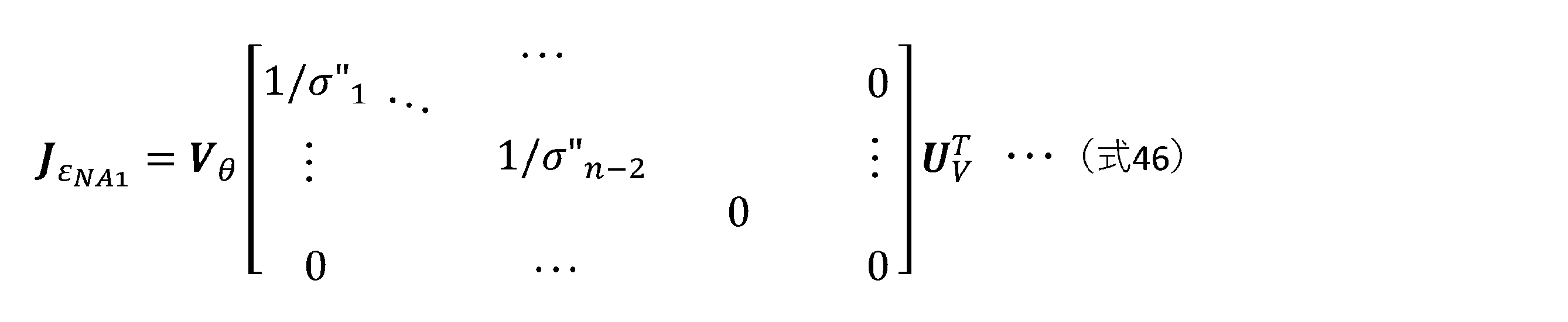
また、2つの特異値σn及びσn-1それぞれが閾値εσnを下回る特異状態において、ロボットアーム11が動作した場合に、2つの特異値σn及びσn-1が閾値εσnを下回ったままで2つの特異値σn及びσn-1の大小関係が入れ替わることがある。このような場合においても、情報処理装置100は、特異値σn及びσn-1それぞれに対応する寄与度wn及びwn-1の状態に関する4つのケースに対応して、ロボットアーム11の分解速度制御を行う。
(1)wn≧εwn及びwn-1≧εwnの第1ケース
情報処理装置100は、状態SCの分解速度制御を行う。例えば、情報処理装置100は、式42及び式11で示される正規化行列JεNを使用した式12に従った分解速度制御、又は、式42及び式11で示される正規化行列JεNを使用した式14に従った分解速度制御を行い得る。しかしながら、2つの特異値σn及びσn-1の大小関係が入れ替わる直前は、特異値σn及びσn-1の差異は小さいため、入れ替わりにより寄与度wnが減少しても、ノルム||JεNuN||が閾値κθ未満となることはなく、それ故、情報処理装置100は、式14に従った分解速度制御を行うことがない。これ故、ロボットアーム11は、特異値σnに対応するセルフモーションと特異値σn-1に対応するセルフモーションとの複合動作を行い得る。さらに、特異値σn及びσn-1の大小関係が入れ替わっても、関節JTの速度指令値に変化がなく、ロボットアーム11の動作はスムーズに遷移し得る。
情報処理装置100は、状態SCの分解速度制御を行う。例えば、情報処理装置100は、式42及び式11で示される正規化行列JεNを使用した式12に従った分解速度制御、又は、式42及び式11で示される正規化行列JεNを使用した式14に従った分解速度制御を行い得る。しかしながら、2つの特異値σn及びσn-1の大小関係が入れ替わる直前は、特異値σn及びσn-1の差異は小さいため、入れ替わりにより寄与度wnが減少しても、ノルム||JεNuN||が閾値κθ未満となることはなく、それ故、情報処理装置100は、式14に従った分解速度制御を行うことがない。これ故、ロボットアーム11は、特異値σnに対応するセルフモーションと特異値σn-1に対応するセルフモーションとの複合動作を行い得る。さらに、特異値σn及びσn-1の大小関係が入れ替わっても、関節JTの速度指令値に変化がなく、ロボットアーム11の動作はスムーズに遷移し得る。
(2)wn≧εwn及びwn-1<εwnの第2ケース
寄与度wnが閾値εwn以上であるため、情報処理装置100は、状態SCの分解速度制御を行う。例えば、情報処理装置100は、式42及び式11で示される正規化行列JεNを使用した式12に従った分解速度制御、又は、式42及び式11で示される正規化行列JεNを使用した式14に従った分解速度制御を行い得る。ロボットアーム11がセルフモーションを行う際、特異値σnに対応するセルフモーションが支配的になる。この状態で、特異値σn及びσn-1の大小関係が入れ替わると、入れ替わり後の特異値σnの寄与度が閾値を下回り、それ故、情報処理装置100は、状態Pの分解速度制御を行う。しかしながら、特異値σnに対応するセルフモーションが支配的になっている状態は、維持される。
寄与度wnが閾値εwn以上であるため、情報処理装置100は、状態SCの分解速度制御を行う。例えば、情報処理装置100は、式42及び式11で示される正規化行列JεNを使用した式12に従った分解速度制御、又は、式42及び式11で示される正規化行列JεNを使用した式14に従った分解速度制御を行い得る。ロボットアーム11がセルフモーションを行う際、特異値σnに対応するセルフモーションが支配的になる。この状態で、特異値σn及びσn-1の大小関係が入れ替わると、入れ替わり後の特異値σnの寄与度が閾値を下回り、それ故、情報処理装置100は、状態Pの分解速度制御を行う。しかしながら、特異値σnに対応するセルフモーションが支配的になっている状態は、維持される。
(3)wn<εwn及びwn-1≧εwnの第3ケース
寄与度wnが閾値εwnを下回るため、情報処理装置100は、式44の正規化行列JεNAを用いた状態Pの分解速度制御を行う。ロボットアーム11がセルフモーションを行う際、特異値σn-1に対応するセルフモーションが支配的になる。この状態で、特異値σn及びσn-1の大小関係が入れ替わると、エンドエフェクタ12の指令速度において、入れ替わり後の特異値σn-1に対応する方向の指令速度がなかったものとされた状態は、維持される。情報処理装置100は、ユーザインタフェース30の指令により又は自律的に、エンドエフェクタ12の指令速度を零とすることによって、状態Pを抜け出してもよい。
寄与度wnが閾値εwnを下回るため、情報処理装置100は、式44の正規化行列JεNAを用いた状態Pの分解速度制御を行う。ロボットアーム11がセルフモーションを行う際、特異値σn-1に対応するセルフモーションが支配的になる。この状態で、特異値σn及びσn-1の大小関係が入れ替わると、エンドエフェクタ12の指令速度において、入れ替わり後の特異値σn-1に対応する方向の指令速度がなかったものとされた状態は、維持される。情報処理装置100は、ユーザインタフェース30の指令により又は自律的に、エンドエフェクタ12の指令速度を零とすることによって、状態Pを抜け出してもよい。
(4)wn<εwn及びwn-1<εwnの第4ケース
情報処理装置100は、式46の正規化行列JεNA1を用いた状態Pの分解速度制御を行う。正規化行列JεNA1では、特異値σn及びσn-1に対応する方向成分が取り除かれている。このため、特異値σn及びσn-1の大小関係が入れ替わっても、情報処理装置100の分解速度制御は影響を受けない。情報処理装置100は、ユーザインタフェース30の指令により又は自律的に、エンドエフェクタ12の指令速度を零とすることによって、状態Pを抜け出してもよい。
情報処理装置100は、式46の正規化行列JεNA1を用いた状態Pの分解速度制御を行う。正規化行列JεNA1では、特異値σn及びσn-1に対応する方向成分が取り除かれている。このため、特異値σn及びσn-1の大小関係が入れ替わっても、情報処理装置100の分解速度制御は影響を受けない。情報処理装置100は、ユーザインタフェース30の指令により又は自律的に、エンドエフェクタ12の指令速度を零とすることによって、状態Pを抜け出してもよい。
よって、情報処理装置100は、閾値εσnを下回った特異状態にある2つの特異値の大小関係が入れ替わっても、入れ替わりに対応した特別な処理をする必要がない。情報処理装置100は、ロボット10からのフィードバック情報が更新される毎に、ヤコビ行列を決定して特異値分解し、特異値の大小関係に基づいて上述した処理を行うことによって、各状態の分解速度制御を行うことができる。
また、3つ以上の特異値が閾値を下回った場合や、当該特異値に対応する寄与度の中で複数の寄与度が閾値を下回った場合も、上記と同様に行列Σ-1内の要素を適切に変更することで対応できる。このように本手法は、複数の特異状態に同時に陥った場合にも対応できるような一般性を有している。例えば、3つ以上の特異値それぞれが閾値εσnを下回る特異状態において、情報処理装置100は、上述の第1ケースから第4ケースと同様の処理をすることで、各状態の分解速度制御を行ってもよい。3つ以上の特異値の間で大小関係が入れ替わる場合も、情報処理装置100は、上述の第1ケースから第4ケースと同様の処理をすることで、各状態の分解速度制御を行ってもよい。
例えば、第1特異値σnと、第2特異値σn-1と、第2特異値σn-1の次に小さい1つ以上の特異値とを含む、第1特異値σnから第k特異値σn-k+1のいずれもが、閾値εσnを下回る特異状態において、情報処理装置100は、第1特異値σnから第k特異値σn-k+1それぞれに対応する第1寄与度wnから第k寄与度wn-k+1を決定する。なお、kは3以上n以下の自然数である。
情報処理装置100は、第1寄与度wnから第k寄与度wn-k+1に向かって順次、寄与度が閾値εwn以上であるか否かを判定する。情報処理装置100は、閾値εwn以上である寄与度を見つけだすことができたら、閾値εwn以上であると最初に判定した第i寄与度wn-i+1に対応する第i特異値σn-i+1を基準として、式6に示される正規化ヤコビ行列JNの逆行列JN
-1を変換する。iは、1以上k以下の自然数である。第i寄与度wn-i+1の序数iは、閾値εwn以上である寄与度の序数の中で最小である。
上記変換では、情報処理装置100は、逆行列JN
-1内の行列Σ-1に含まれる特異値のうちの第1特異値σnから第(i-1)特異値σn-iを0に置き換える零変換をする。さらに、情報処理装置100は、第(i+1)特異値σn-iから第k特異値σn-k+1に対応する第(i+1)寄与度wn-iから第k寄与度wn-k+1それぞれについて、寄与度が閾値εwn以上であるか否かを判定する。情報処理装置100は、寄与度が閾値εwn未満である特異値を0に置き換える零変換をする。
さらに、情報処理装置100は、2つの零変換後の行列Σ-1のすべての要素を第3比率σn-i+1/εσn倍することで、逆行列JN
-1から変換された新たな正規化行列を算出する。第i特異値σn-i+1は、第i特異値σn-i+1から第k特異値σn-k+1のうちで最小の特異値である。情報処理装置100は、上記の第3ケースと同様に、当該正規化行列を用いた状態Pの分解速度制御を行う。当該正規化行列は、第7逆ヤコビ行列の一例である。
例えば、第1寄与度wnから第k寄与度wn-k+1のいずれもが閾値εwn以上である場合、情報処理装置100は、第3比率として、第1比率σn/εσnを用いる。情報処理装置100は、式6に示される正規化ヤコビ行列JNの逆行列JN
-1内の行列Σ-1のすべての要素を第1比率σn/εσn倍して、式42に示す正規化行列JεNを算出する。情報処理装置100は、上記の第1ケース又は第2ケースと同様に、正規化行列JεNを用いた状態SCの分解速度制御を行う。
例えば、第1寄与度wnから第k寄与度wn-k+1のいずれもが閾値εwn未満である場合、情報処理装置100は、式6に示される正規化ヤコビ行列JNの逆行列JN
-1内の第1特異値σnから第k特異値σn-k+1の全てを0に置き換える零変換をして、新たな正規化行列を算出する。さらに、情報処理装置100は、新たな正規化行列において、零変換後の行列Σ-1のすべての要素を第3比率σn-k+1/εσn倍してもよい。情報処理装置100は、上記の第4ケースと同様に、当該正規化行列を用いた状態Pの分解速度制御を行う。当該正規化行列は、第7逆ヤコビ行列の一例である。
例えば、3つの特異値σn、σn-1及びσn-2それぞれが閾値εσnを下回る特異状態では、それぞれの寄与度wn、wn-1及びwn-2の閾値εwnに対する状態に関する8つのケースに対応して、情報処理装置100は、ロボットアーム11の分解速度制御を行ってもよい。各ケースでの処理は、第1から第4ケースの処理と同様に行うことができる。
また、ロボットアーム11の動作では、3つの特異値σn、σn-1及びσn-2が同時に閾値εσnを下回る特異状態に至るのではなく、2つの特異値が閾値εσnを下回る特異状態に至った後に、さらに、1つの特異値が閾値εσnを下回る状態に至ることが多い。
例えば、図4に示すロボットアーム11は、3つの特異値が閾値εσnを下回る特異状態である。図5から図7に示すロボットアーム11は、1つの特異値が閾値εσnを下回る特異状態である。ロボットアーム11は、まず、図7に示す肩特異姿勢に至り、次いで、肘を伸ばすようにして図5に示す肘特異姿勢に至り、その後又は同時に、図6に示す手首特異姿勢に至ることで、図4に示すような3つの特異値が閾値εσnを下回る特異姿勢に至り得る。
また、2つの特異値σn及びσn-1それぞれが閾値εσnを下回る特異状態において、情報処理装置100は、特異値σn及びσn-1の大小関係に依存しない処理をしてもよい。情報処理装置100は、式6に示される正規化ヤコビ行列JNの逆行列JN
-1内の行列Σ-1のすべての要素をσn/εσn倍して、式42に示す新たな行列JεNを算出する。さらに、情報処理装置100は、特異値σn-1を含む要素を、特異値σnを含む要素と同じ値1/εσnに置き換えることで、以下の式47に示す新たな行列JεNDを算出する。これにより、特異値σn、σn-1を含む要素それぞれの発散を防ぐことができる。情報処理装置100は、式47の正規化行列JεNDを用いた分解速度制御を行うことができる。
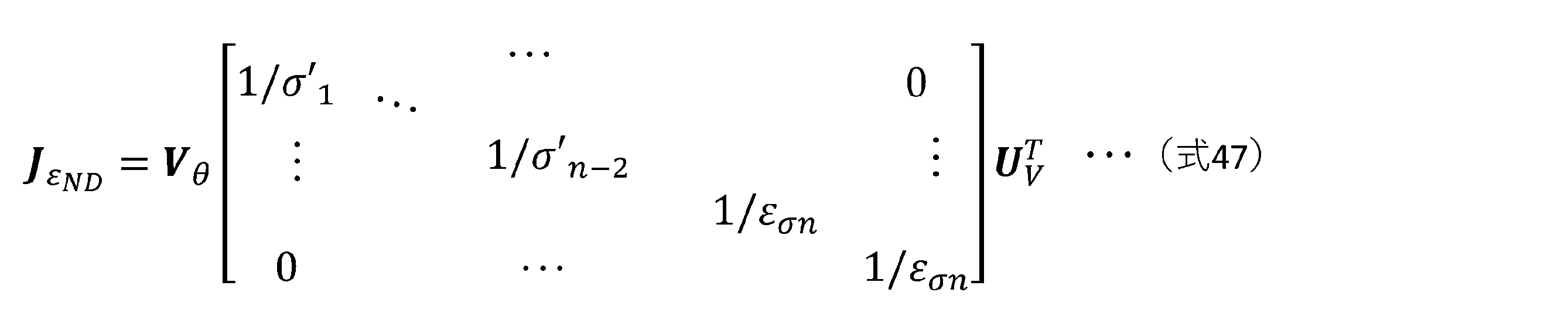
[ロボットシステムの変形例]
実施の形態に係るロボットシステム1の変形例を説明する。変形例に係るロボットシステム1Aは、ユーザインタフェース30とロボット10とが通信網Nを介して接続される遠隔操作ロボットシステムである点で、実施の形態と異なる。以下、本変形例について、実施の形態と異なる点を中心に説明し、実施の形態と同様の点の説明を適宜省略する。
実施の形態に係るロボットシステム1の変形例を説明する。変形例に係るロボットシステム1Aは、ユーザインタフェース30とロボット10とが通信網Nを介して接続される遠隔操作ロボットシステムである点で、実施の形態と異なる。以下、本変形例について、実施の形態と異なる点を中心に説明し、実施の形態と同様の点の説明を適宜省略する。
図14は、変形例に係るロボットシステム1Aの構成の一例を示す図である。図14に示すように、ロボットシステム1Aは、1つ以上のロボットエリアARそれぞれに配置されるロボット10及び制御装置20と、1つ以上のユーザエリアAUそれぞれに配置されるユーザインタフェース30と、ロボットエリアARとユーザエリアAUとをマッチングしてそれぞれに含まれる制御装置20とユーザインタフェース30とを通信網Nを介してデータ通信可能に接続する仲介装置300とを含む。情報処理装置100の機能の少なくとも一部は、ユーザインタフェース30及び仲介装置300の一方又は両方によって実現される。制御装置20は、電力制御回路200を少なくとも含む。限定されないが、本変形例では、複数のロボットエリアARと、複数のユーザエリアAUとが、ロボットシステム1Aの対象として存在する。
ロボットシステム1Aは、ロボットエリアARに、撮像装置14a及び14bと、ロボット通信装置15とをさらに含む。撮像装置14a及び14bは、カメラを含み、制御装置20と接続される。撮像装置14aは、ロボット10に配置され、例えば、ロボットアーム11に配置され、エンドエフェクタ12及びその処理対象物Wを撮像する。撮像装置14bは、ロボット10全体を撮像するように、ロボット10以外の位置に配置される。ロボット通信装置15は、モデム、ONU(Optical Network Unit:光回線の終端装置)、ルータ又はモバイルデータ通信機器を含む。ロボット通信装置15は、制御装置20を通信網Nに接続する。制御装置20は、通信網Nを介して、ユーザインタフェース30及び仲介装置300と情報、指令及びデータを送受信できる。制御装置20は、撮像装置14a及び14bによって取得された画像データを送信できる。
ロボットシステム1Aは、ユーザエリアAUに、提示装置31と、ユーザ通信装置32とをさらに含む。提示装置31は、ユーザインタフェース30と接続され、操作者Pに情報を知覚可能に提示する。提示装置31は、少なくともディスプレイを含み、さらに、スピーカ等を含んでもよい。ユーザ通信装置32は、モデム、ONU、ルータ又はモバイルデータ通信機器を含む。ユーザ通信装置32は、ユーザインタフェース30を通信網Nに接続する。ユーザインタフェース30は、通信網Nを介して、制御装置20及び仲介装置300と情報、指令及びデータを送受信できる。提示装置31は、ユーザインタフェース30が受信する撮像装置14a及び14bの画像データを画像として提示する。ユーザインタフェース30は、提示装置31、ユーザ通信装置32又はこれらの両方を含んでもよい。
仲介装置300は、通信網Nを介した通信を管理する。仲介装置300は、コンピュータ装置を含むサーバの構成を有してもよい。仲介装置300は、ユーザ通信装置32の認証、ユーザ通信装置32とロボット通信装置15との接続及び接続解除等を管理する。例えば、仲介装置300は、認証されたユーザ通信装置32に接続されたユーザインタフェース30によって指定されるロボット10のロボット通信装置15と当該ユーザ通信装置32とを接続する。つまり、仲介装置300は、ユーザ通信装置32とロボット通信装置15とをマッチングして接続する。仲介装置300は、ロボット通信装置15とユーザ通信装置32との間のデータの送受信を管理し、当該データは仲介装置300を経由してもよい。
通信網Nは特に限定されず、例えば、ローカルエリアネットワーク(Local Area Network:LAN)、広域ネットワーク(Wide Area Network:WAN)、インターネット、又はこれらの2つ以上の組み合わせを含むことができる。通信網Nは、ブルートゥース(Bluetooth)(登録商標)及びZigBee(登録商標)などの近距離無線通信、ネットワーク専用回線、通信事業者の専用回線、公衆交換電話網(Public Switched Telephone Network:PSTN)、モバイル通信網、インターネット網、衛星通信、又は、これらの2つ以上の組み合わせを用いるように構成され得る。モバイル通信網は、第4世代移動通信システム及び第5世代移動通信システム等を用いるものであってもよい。通信網Nは、1つ又は複数のネットワークを含むことができる。本変形例では、通信網Nはインターネットである。
本変形例では、仲介装置300は、実施の形態に係る情報処理装置100の機能を含む。仲介装置300は、制御装置20又は当該制御装置20と接続されたユーザインタフェース30から、当該制御装置20と接続されたロボット10の諸元に関する情報を受信する。仲介装置300は、制御装置20からロボット10のフィードバック情報を受信し、フィードバック情報とロボット10の諸元に関する情報とを用いてヤコビ行列を生成する。仲介装置300は、当該ヤコビ行列に基づき、実施の形態に係る情報処理装置100が行う特異点に関する処理を行う。
ロボットエリアARの制御装置20が、情報処理装置100の機能を備えていなくても、仲介装置300は、情報処理装置100として機能して、ロボット10に、特異点に対応した動作をさせることができる。仲介装置300は、ロボット10の諸元に関する情報を得ることができれば、情報処理装置100として機能できる。仲介装置300は、ユーザエリアAUの操作者Pが、提示装置31によって提示される限られた領域の画像に基づいて特異点を回避するようにロボット10を操作することを不要にする。操作者Pは、特異点を考慮せずにロボット10を操作できる。仲介装置300は、様々な操作者Pが様々なロボット10を操作することを容易にする。
なお、ユーザインタフェース30が、実施の形態に係る情報処理装置100の機能の一部又は全部を備えてもよい。ユーザインタフェース30は、情報処理装置100の機能をアプリケーションソフトとして組み入れていてもよい。例えば、ユーザインタフェース30が、実施の形態に係る情報処理装置100の機能の全部を備える場合、仲介装置300は、ユーザインタフェース30と制御装置20とのマッチングと、ユーザインタフェース30と制御装置20との間の情報、指令及びデータの送受信の仲介とを行ってもよい。例えば、ユーザインタフェース30が、実施の形態に係る情報処理装置100の機能の一部を備え、仲介装置300が、情報処理装置100の機能の他部又は全部を備えてもよい。ユーザインタフェース30が備える情報処理装置100の機能と仲介装置300が備える情報処理装置100の機能とは、重複してもよく、重複していなくてもよい。例えば、仲介装置300は、ユーザインタフェース30が情報処理装置100として実行できない処理を実行し、処理結果をユーザインタフェース30に提供してもよい。
制御装置20が、情報処理装置100の機能の一部を備えてもよい。この場合、仲介装置300が、情報処理装置100の機能の他部又は全部を備えてもよく、ユーザインタフェース30が、情報処理装置100の機能の他部又は全部を備えてもよい。制御装置20、ユーザインタフェース30及び仲介装置300のそれぞれが、情報処理装置100の機能の一部を備えてもよい。この場合、仲介装置300は、情報処理装置100の機能の全部を備えてもよい。制御装置20が備える情報処理装置100の機能と、ユーザインタフェース30が備える情報処理装置100の機能と、仲介装置300が備える情報処理装置100の機能とは、重複してもよく、重複していなくてもよい。
[その他]
以上、本開示の例示的な実施の形態及び変形例について説明したが、本開示は、上記実施の形態及び変形例に限定されない。すなわち、本開示の範囲内で種々の変形及び改良が可能である。例えば、各種変形を実施の形態又は変形例に施したもの、及び、異なる実施の形態及び変形例における構成要素を組み合わせて構築される形態も、本開示の範囲内に含まれる。
以上、本開示の例示的な実施の形態及び変形例について説明したが、本開示は、上記実施の形態及び変形例に限定されない。すなわち、本開示の範囲内で種々の変形及び改良が可能である。例えば、各種変形を実施の形態又は変形例に施したもの、及び、異なる実施の形態及び変形例における構成要素を組み合わせて構築される形態も、本開示の範囲内に含まれる。
例えば、実施の形態及び変形例では、情報処理装置100は、ロボット10の手動操縦の場合に、特異点に関する処理を行うが、これに限定されない。情報処理装置100は、ロボット10の自動操縦の場合、つまり、ロボット10が教示データ等の予め設定されたデータに従って自律的に動作する場合に、特異点に関する処理を行ってもよい。これにより、教示データが、特異点を回避するようなロボット10の動作のデータを含んでいなくとも、情報処理装置100は、当該教示データに従ってロボット10に動作させる際に、特異点に関する処理を行い、ロボット10に特異点に対応して動作させることができる。
本開示の技術の各態様例は、以下のように挙げられる。本開示の第1態様に係るプログラムは、複数の関節と前記複数の関節が動作することによって移動される移動部とを含むロボットの動作を制御するプログラムであって、前記複数の関節の動作速度と前記移動部の移動速度とを関連付ける第1ヤコビ行列を特異値分解して、前記関節の動作速度空間を表す第1基底ベクトルを要素に含む第1行列と、前記移動部の移動速度空間を表す第2基底ベクトルを要素に含む第2行列と、特異値を対角要素に含む第1特異行列とを含む、第2ヤコビ行列を生成することと、前記特異値と第1閾値との比較結果に基づき、前記ロボットが特異点にある場合及び前記ロボットが前記特異点に接近している場合に実行される第1処理と、前記ロボットが前記特異点から離れている場合に実行される第2処理とのうちから、実行対象の処理を決定して実行することと、前記第1処理において、前記第1特異行列内の対角要素を変換して第3ヤコビ行列を生成することと、前記第1処理において、前記第3ヤコビ行列と、前記移動部の移動を指令する移動指令値とを用いて、前記複数の関節の動作を指令する動作指令値を決定し出力することと、前記第2処理において、前記第1ヤコビ行列又は前記第2ヤコビ行列と、前記移動指令値とを用いて、前記動作指令値を決定し出力することとを、コンピュータに実行させる。
上記態様によると、第1処理において、第1特異行列内の対角要素が変換されることにより、第2ヤコビ行列から第3ヤコビ行列が生成される。この場合、ロボットが特異点にある状態及びロボットが特異点に接近している状態に対応するように、対角要素が変換されてもよい。例えば、ロボットが特異点にある状態及びロボットが特異点に接近している状態で、第2ヤコビ行列の逆行列の要素が発散しないように、対角要素が変換されてもよい。上記の変換により、ロボットが特異点にある状態及びロボットが特異点に接近している状態で、関節の速度が急激に変化することを防ぐことができる。このように、第1特異行列内の対角要素を変換するという新規な方法によって、特異点に対応したロボットの動作制御が可能である。
ここで、特異点近傍では、通常の分解速度制御では関節速度が過大になり得る。このような問題を解決する方法として、特異点低感度分解と特異点適合法とがある。特異点低感度分解は、関節速度が過大になることを抑制できるが、その代わりに、本来指令した軌道からエンドエフェクタが逸脱するという問題がある。特異点適合法は、関節速度が過大になることを抑制しつつ、本来指令した軌道からエンドエフェクタが逸脱もしない。ただし、特異点適合法は、ヤコビ行列の余因子行列の解析的な計算を必要とし、ある特定のアームに適用するために非常に手間を要する。
従来の特異点適合法が、ヤコビ行列の余因子行列の計算を要していたのに対し、本願発明者は、ヤコビ行列を特異値分解し、その特異値の逆数の比が保存されるように、特異値をスケーリングすることを見出した。これにより、本願発明者は、従来の特異点適宜合法におけるヤコビ行列の余因子行列と同等の効果を持つ行列を、解析計算ではなく数値計算で求めることをできることを見出した。
上記第1態様において、本開示の第2態様に係るプログラムは、前記動作指令値の決定に用いたヤコビ行列に前記動作指令値を適用して得られるベクトルのノルムである第1ノルムを算出することと、前記第1ノルムが前記移動指令値よりも大きい場合、前記第1ノルムを用いて前記動作指令値を補正して補正動作指令値を決定し、前記動作指令値として前記補正動作指令値を出力することと、前記第1ノルムが前記移動指令値以下である場合、前記動作指令値を出力することとを、コンピュータに実行させてもよい。
上記態様によると、ロボットが移動部を移動する速度の上限を設定し、当該上限以下の速度で移動部が移動するように、複数の関節の動作指令値を決定することができる。よって、移動部の移動速度の過度な上昇を防ぐことができる。
上記の第1態様又は第2態様において、本開示の第3態様に係るプログラムは、前記ロボットの諸元の情報である第1情報を受け取り、前記第1情報と、前記複数の関節の状態の情報とを用いて、前記第1ヤコビ行列を生成することを、コンピュータに実行させてもよい。
上記態様によると、第1情報を取得し、取得した第1情報を用いて、第1ヤコビ行列を生成することができる。よって、ロボットに合わせた第1ヤコビ行列の設定が可能である。
上記の第1態様から第3態様のいずれかにおいて、本開示の第4態様に係るプログラムは、前記特異値の最小値が前記第1閾値よりも小さい場合に前記第1処理の実行を決定し、前記特異値の最小値が前記第1閾値以上の場合に前記第2処理の実行を決定することを、コンピュータに実行させてもよい。
上記態様によると、ロボットが特異点に接近するに従って、最小の特異値が小さくなる。最小の特異値が第1閾値よりも小さいか否かという条件は、ロボットが特異点に接近した状態であるか否かを決定するための条件、つまり、第1処理の実行の有無を決定するための条件とすることができる。よって、第1処理の実行の有無の確実な決定が可能である。
上記の第1態様から第4態様のいずれかにおいて、本開示の第5態様に係るプログラムは、前記第2ヤコビ行列の逆行列である第2逆ヤコビ行列を生成することであって、前記第2逆ヤコビ行列は、前記第1行列、前記第2行列及び前記第1特異行列それぞれから変換された第1変換行列、第2変換行列及び第1変換特異行列を含むことと、前記第1処理において、前記第1変換特異行列内の対角要素を変換する第1変換を行うことにより、前記第3ヤコビ行列の逆行列である第3逆ヤコビ行列を生成することと、前記第1処理において、前記第3逆ヤコビ行列に前記移動指令値を適用して、前記動作指令値を決定することと、前記第2処理において、前記第1ヤコビ行列の逆行列である第1逆ヤコビ行列又は前記第2逆ヤコビ行列に、前記移動指令値を適用して、前記動作指令値を決定することとを、コンピュータに実行させてもよい。
上記態様によると、ヤコビ行列の逆行列である逆ヤコビ行列は、移動部の移動速度を適用されて、複数の関節の動作速度を得ることができる。逆ヤコビ行列を使用することによって、移動指令値に対する動作指令値の決定が可能である。
上記の第5態様において、本開示の第6態様に係るプログラムは、前記第1変換では、前記第1変換特異行列内の前記特異値を含む対角要素間の比率を維持するように、前記対角要素それぞれを変換することを、コンピュータに実行させてもよい。
上記態様によると、第1変換では、第1変換特異行列内の特異値を含む対角要素間の比率が維持される。よって、第1変換は、逆ヤコビ行列が本来持っている移動指令値と動作指令値との関係性を維持する。第1逆ヤコビ行列、第2逆ヤコビ行列及び第3逆ヤコビ行列は、同じ移動指令値を適用されると、同様の方向に移動部を移動する動作指令値を得ることができる。ロボットが特異点の近傍であるか否かに関係なく、指令される方向への移動部の動作を維持することができる。
上記の第6態様において、本開示の第7態様に係るプログラムは、前記第1変換では、前記第1変換特異行列内の前記特異値の最小値と前記第1閾値との第1比率を、前記対角要素それぞれに乗算することを、コンピュータに実行させてもよい。
上記態様によると、第1変換特異行列において、最小の特異値が0に近づいても、最小の特異値を含む対角要素は、発散しない。よって、特異点の近傍において、当該対角要素に対応する関節の速度が急激に変化することが防がれる。
上記の第5態様から第7態様のいずれかにおいて、本開示の第8態様に係るプログラムは、前記第1処理において、前記移動指令値に含まれる前記移動部の指令速度の方向を表す方向ベクトルを前記第3逆ヤコビ行列に適用して得られる、ベクトルのノルムである第2ノルムを算出することと、前記第1処理において、前記第2ノルムが第2閾値以上である場合に、前記第2ノルムを用いて正規化した前記第3逆ヤコビ行列に、前記移動指令値を適用して、前記動作指令値を決定することと、前記第1処理において、前記第2ノルムが前記第2閾値未満である場合に、前記第2ノルムを用いて正規化した前記第3逆ヤコビ行列において、前記第2ノルムを前記第2閾値に変更して得られる逆ヤコビ行列に、前記移動指令値を適用して、前記動作指令値を決定することとを、コンピュータに実行させてもよい。
上記態様によると、第2ノルムは、移動部の指令速度の方向成分に対応する移動部の移動速度の大きさを示す。第2ノルムが小さくなると、正規化した第3逆ヤコビ行列が発散し得る。第2ノルムが第2閾値未満である場合に、正規化した第3逆ヤコビ行列において、第2ノルムを第2閾値に変更することによって、正規化した第3逆ヤコビ行列の発散が防がれる。よって、特異点の近傍において、移動部の速度が急激に変化することが防がれる。
上記の第5態様から第8態様のいずれかにおいて、本開示の第9態様に係るプログラムは、前記第1処理において、前記移動指令値に含まれる前記移動部の指令速度が、前記第2基底ベクトルの方向に寄与する割合である寄与度を決定することと、前記第1処理において、前記寄与度が第3閾値以上である場合に、前記第3逆ヤコビ行列を用いて、前記動作指令値を決定することと、前記第1処理において、前記寄与度が前記第3閾値未満である場合に、前記第1変換後の前記第1変換特異行列内の前記特異値の最小値に対応する対角要素の値を0にするように、前記第3逆ヤコビ行列を第4逆ヤコビ行列に変換することと、前記第1処理において、前記寄与度が前記第3閾値未満である場合に、前記第4逆ヤコビ行列に前記移動指令値を適用して、前記動作指令値を決定することとを、コンピュータに実行させてもよい。
上記態様によると、移動部の指令速度が、移動部の移動速度空間を表す第2基底ベクトルの方向に寄与しない成分を含む場合、第1変換後の第1変換特異行列内の最小の特異値に対応する対角要素の値を0にするように、第3逆ヤコビ行列が第4逆ヤコビ行列に変換される。第4逆ヤコビ行列を用いることによって、移動指令値に対する、動作指令値によって実現される移動部の速度の誤差が低減できる。
上記の第5態様から第9態様のいずれかにおいて、本開示の第10態様に係るプログラムは、前記第1処理において、前記移動指令値に含まれる前記移動部の指令速度が、前記第2基底ベクトルの方向に寄与する割合である寄与度のうち、前記第1変換特異行列内の前記特異値のうちで最小である第1特異値に対応する第1寄与度を決定することと、前記第1処理において、前記第1特異値と、前記第1変換特異行列内の前記特異値のうちで前記第1特異値の次に小さい第2特異値とのいずれもが、前記第1閾値よりも小さく、前記第1寄与度が第3閾値以上である場合、前記第1変換特異行列内の対角要素それぞれに、前記第1特異値と前記第1閾値との第1比率を乗算して、前記第3逆ヤコビ行列を生成し、前記第3逆ヤコビ行列に前記移動指令値を適用して、前記動作指令値を決定することと、前記第1処理において、前記第1特異値と前記第2特異値とのいずれもが、前記第1閾値よりも小さく、前記第1特異値の前記第1寄与度が前記第3閾値未満である場合、前記第1変換特異行列内の前記第1特異値に対応する対角要素の値を0にし、前記第1変換特異行列内の対角要素それぞれに、前記第2特異値と前記第1閾値との第2比率を乗算して、第5逆ヤコビ行列を生成し、前記第5逆ヤコビ行列に前記移動指令値を適用して、前記動作指令値を決定することとを、コンピュータに実行させてもよい。
上記態様によると、第1特異値及び第2特異値が第1閾値よりも小さい場合、第1特異値に対応する第1寄与度と第3閾値との関係に応じた逆ヤコビ行列を決定し、決定した逆ヤコビ行列を使用した動作指令値の決定が可能である。よって、2つの特異値が第1閾値よりも小さいような、ロボットが特異点にある又は特異点に接近している状態に対応した、ロボットの動作制御が可能である。
上記の第10態様において、本開示の第11態様に係るプログラムは、前記第1処理において、前記第1特異値と前記第2特異値とのいずれもが、前記第1閾値よりも小さく、前記第1寄与度及び前記第2特異値に対応する第2寄与度が前記第3閾値未満である場合、前記第1変換特異行列内の前記第1特異値及び前記第2特異値に対応する対角要素の値を0にし、前記第1変換特異行列内の対角要素それぞれに、前記第2比率を乗算して、第6逆ヤコビ行列を生成し、前記第6逆ヤコビ行列に前記移動指令値を適用して、前記動作指令値を決定することとを、コンピュータに実行させてもよい。
上記態様によると、移動部の指令速度が、第1特異値及び第2特異値それぞれに対応する第2基底ベクトルの方向に寄与しない成分を含む場合、第1変換特異行列内の第1特異値及び第2特異値に対応する対角要素の値を0にするように、第6逆ヤコビ行列が生成される。第6逆ヤコビ行列を用いることによって、第1特異値及び第2特異値に対応する成分が取り除かれた動作指令値が生成される。よって、移動指令値に対する、動作指令値によって実現される移動部の速度の誤差が低減できる。
上記の第5態様から第11態様において、本開示の第12態様に係るプログラムは、前記第1処理において、前記第1変換特異行列内の前記特異値のうちで最小である第1特異値と、前記第1変換特異行列内の前記特異値のうちで前記第1特異値の次に小さい2つ以上の前記特異値とを含む、前記第1特異値から第k特異値(kは3以上の自然数)のいずれもが、前記第1閾値よりも小さい場合、前記移動指令値に含まれる前記移動部の指令速度が、前記第2基底ベクトルにおける前記第1特異値から前記第k特異値それぞれに対応する方向に寄与する割合である第1寄与度から第k寄与度を決定することと、前記第1処理において、前記第1寄与度から前記第k寄与度が第3閾値以上である場合に、前記第1変換では、前記第1変換特異行列内の前記対角要素それぞれに、前記第1特異値と前記第1閾値との第1比率を乗算して、前記第3逆ヤコビ行列を生成し、前記第3逆ヤコビ行列に前記移動指令値を適用して、前記動作指令値を決定することと、前記第1処理において、前記第1寄与度から前記第k寄与度の少なくとも1つが前記第3閾値未満である場合に、前記第1変換では、前記第1変換特異行列内の前記寄与度が前記第3閾値未満である前記特異値に対応する対角要素の値を0にする零変換をし、且つ、前記零変換後の前記第1変換特異行列内の前記寄与度が前記第3閾値未満である前記特異値を除いた中で最小の特異値と前記第1閾値との第3比率を、前記零変換後の前記第1変換特異行列内の対角要素に乗算して、第7逆ヤコビ行列に変換することと、前記第1処理において、前記第1寄与度から前記第k寄与度の少なくとも1つが前記第3閾値未満である場合に、前記第7逆ヤコビ行列に前記移動指令値を適用して、前記動作指令値を決定することとを、コンピュータに実行させてもよい。
上記態様によると、3つ以上の特異値が第1閾値よりも小さい場合も、2つの特異値が第1閾値よりも小さい場合と同様にして、各特異値に対応する寄与度に応じた逆ヤコビ行列を決定し、決定した逆ヤコビ行列を使用した動作指令値の決定が可能である。よって、3つの特異値が第1閾値よりも小さいような、ロボットが特異点にある又は特異点に接近している状態に対応した、ロボットの動作制御が可能である。
上記の第1態様から第12態様のいずれかにおいて、本開示の第13態様に係るプログラムは、前記第1ヤコビ行列を時間微分して第8ヤコビ行列を生成することと、前記第1処理中での前記複数の関節の動作速度のうち、前記ロボットのセルフモーションに対応する前記第2基底ベクトル内の速度を前記第8ヤコビ行列に適用して加速度ベクトルを生成することと、前記第1処理において、前記加速度ベクトルのノルムが第4閾値以上である場合、前記加速度ベクトルのノルムが最大値を示すか否かを決定することと、前記加速度ベクトルのノルムが最大値を示す場合に、前記複数の関節の動作を停止する指令を出力することとを、コンピュータに実行させてもよい。
上記態様によると、加速度ベクトルのノルムが第4閾値未満である場合、ロボットは、セルフモーションを継続可能な小さい加速度を発生する。加速度ベクトルのノルムが第4閾値以上である場合、ロボットは、セルフモーションにより特異点の近傍にある状態から抜け出すことができるような加速度を発生する。加速度ベクトルのノルムが第4閾値以上であり、且つ加速度ベクトルのノルムが最大値を示す場合、ロボットは、特異点に到達し、セルフモーションにより特異点からの逸脱と特異点への到達とを繰り返す振動現象を発生し得る。このような場合に、複数の関節の動作を一旦停止し、その後に動作することによって、振動現象を防ぐことができる。
本開示の第14態様に係る記憶媒体は、上記の第1態様から第13態様のいずれかのプログラムを記憶する。上記態様によると、本開示の各態様に係るプログラムと同様の効果が得られる。記憶媒体は、非一時的で有形なコンピュータ読み取り可能な媒体であってもよい。記憶媒体は、非一時的で有形なコンピュータ読み取り可能な記録媒体であってもよい。記憶媒体の例は、1つ又は複数の半導体ベースの若しくは他の集積回路(IC)、ROM、EEPROM(Electrically Erasable and Programmable Read Only Memory )、EPROM、フラッシュメモリ、CD-ROM(Compact Disc Read Only Memory )、CD-RW(Compact Disc Rewritable )、DVD(Digital Versatile Disk)、ハードディスクドライブ(HDD)、ハイブリッドハードドライブ(HHD)、光ディスク、光ディスクドライブ(ODD)、光磁気ディスク、光磁気ドライブ、フロッピィ・ディスク、フロッピィ・ディスク・ドライブ(FDD)、磁気テープ、固体ドライブ(SSD)、RAMドライブ、セキュア・デジタル・カード、セキュア・デジタル・ドライブ、任意の他の適切な記憶媒体、又はこれらの2つ以上の組合せを含むことができる。集積回路の例は、フィールド・プログラマブル・ゲート・アレイ(FPGA)、特定用途向けIC(ASIC)などを含み得る。記憶媒体は、揮発性、不揮発性、又は、揮発性と不揮発性との組合せであってもよい。
本開示の第15態様に係る情報処理装置は、上記の第1態様から第13態様のいずれかのプログラムを記憶するメモリと、前記メモリに記憶された前記プログラムを実行するプロセッサとを含む。上記態様によると、本開示の各態様に係るプログラムと同様の効果が得られる。
本開示の第16態様に係るシステムは、上記の第1態様から第13態様のいずれかのプログラムを実行するコンピュータを含む情報処理装置と、前記ロボットとを含み、前記情報処理装置は、ロボット操作が入力されるユーザインタフェース及び前記ロボットと接続され、前記情報処理装置は、前記ユーザインタフェースから、前記移動部を移動する指令を受信し、前記移動部を移動する指令に基づいた前記移動指令値を用いて、前記動作指令値を決定し、前記動作指令値を前記ロボットに送信し、前記情報処理装置は、前記ロボットの諸元の情報である第1情報を入力され、前記第1情報を用いて、前記第1ヤコビ行列を生成する。上記態様によると、本開示の各態様に係るプログラムと同様の効果が得られる。
本開示の第17態様に係るロボットの動作を制御する方法は、複数の関節と前記複数の関節が動作することによって移動される移動部とを含むロボットの動作を制御する方法であって、前記複数の関節の動作速度と前記移動部の移動速度とを関連付ける第1ヤコビ行列を特異値分解して、前記関節の動作速度空間を表す第1基底ベクトルを要素に含む第1行列と、前記移動部の移動速度空間を表す第2基底ベクトルを要素に含む第2行列と、特異値を対角要素に含む第1特異行列とを含む、第2ヤコビ行列を生成することと、前記特異値と第1閾値との比較結果に基づき、前記ロボットが特異点にある場合及び前記ロボットが前記特異点に接近している場合に実行される第1処理と、前記ロボットが前記特異点から離れている場合に実行される第2処理とのうちから、実行対象の処理を決定して実行することと、前記第1処理において、前記第1特異行列内の対角要素を変換して第3ヤコビ行列を生成することと、前記第1処理において、前記第3ヤコビ行列と、前記移動部の移動を指令する移動指令値とを用いて、前記複数の関節の動作を指令する動作指令値を決定し出力することと、前記第2処理において、前記第1ヤコビ行列又は前記第2ヤコビ行列と、前記移動指令値とを用いて、前記動作指令値を決定し出力することとを、含む。上記態様によると、本開示の各態様に係るプログラムと同様の効果が得られる。
本開示のプログラムは、例えば、非一時的で有形なコンピュータ読み取り可能な記録媒体に記録されたプログラムであってもよく、記録媒体のドライブ装置を用いて当該記録媒体から読み出されコンピュータにインストールされるように構成されてもよい。当該プログラムは、例えば、インターネット等の伝送媒体を介して流通させることができるプログラムであってもよく、コンピュータにダウンロードされインストールされるように構成されてもよい。
本開示の方法の一部及び全部は、例えば、CPU、LSIなどの回路、ICカード又は単体のモジュール等によって、実現されてもよい。本開示の方法に含まれる複数の要素は、1つの装置によって実現されてもよく、2つ以上の装置によって分担して実現されてもよい。
本明細書で開示する要素の機能は、開示された機能を実行するよう構成又はプログラムされた汎用プロセッサ、専用プロセッサ、集積回路、ASIC、従来の回路、及び/又は、それらの組み合わせ、を含む回路又は処理回路を使用して実行できる。プロセッサは、トランジスタやその他の回路を含むため、処理回路又は回路と見なされる。本開示において、回路、ユニット、又は手段は、列挙された機能を実行するハードウェアであるか、又は、列挙された機能を実行するようにプログラムされたハードウェアである。ハードウェアは、本明細書に開示されているハードウェアであってもよいし、あるいは、列挙された機能を実行するようにプログラム又は構成されているその他の既知のハードウェアであってもよい。ハードウェアが回路の一種と考えられるプロセッサである場合、回路、手段、又はユニットはハードウェアとソフトウェアの組み合わせであり、ソフトウェアはハードウェア及び/又はプロセッサの構成に使用される。
本明細書で用いた序数、数量等の数字は、全て本開示の技術を具体的に説明するために例示するものであり、本開示は例示された数字に制限されない。構成要素間の接続関係は、本開示の技術を具体的に説明するために例示するものであり、本開示の機能を実現する接続関係はこれに限定されない。
本開示は、その本質的な特徴の範囲から逸脱することなく、様々なかたちで実施され得るように、本開示の範囲は、明細書の記載よりも添付の請求項によって定義されるため、例示的な実施の形態及び変形例は、例示的なものであって限定的なものではない。請求項及びその範囲内にあるすべての変更、又は、請求項及びその範囲の均等物は、請求項によって包含されることが意図されている。
Claims (17)
- 複数の関節と前記複数の関節が動作することによって移動される移動部とを含むロボットの動作を制御するプログラムであって、
前記複数の関節の動作速度と前記移動部の移動速度とを関連付ける第1ヤコビ行列を特異値分解して、前記関節の動作速度空間を表す第1基底ベクトルを要素に含む第1行列と、前記移動部の移動速度空間を表す第2基底ベクトルを要素に含む第2行列と、特異値を対角要素に含む第1特異行列とを含む、第2ヤコビ行列を生成することと、
前記特異値と第1閾値との比較結果に基づき、前記ロボットが特異点にある場合及び前記ロボットが前記特異点に接近している場合に実行される第1処理と、前記ロボットが前記特異点から離れている場合に実行される第2処理とのうちから、実行対象の処理を決定して実行することと、
前記第1処理において、前記第1特異行列内の対角要素を変換して第3ヤコビ行列を生成することと、
前記第1処理において、前記第3ヤコビ行列と、前記移動部の移動を指令する移動指令値とを用いて、前記複数の関節の動作を指令する動作指令値を決定し出力することと、
前記第2処理において、前記第1ヤコビ行列又は前記第2ヤコビ行列と、前記移動指令値とを用いて、前記動作指令値を決定し出力することとを、コンピュータに実行させる
プログラム。 - 前記動作指令値の決定に用いたヤコビ行列に前記動作指令値を適用して得られるベクトルのノルムである第1ノルムを算出することと、
前記第1ノルムが前記移動指令値よりも大きい場合、前記第1ノルムを用いて前記動作指令値を補正して補正動作指令値を決定し、前記動作指令値として前記補正動作指令値を出力することと、
前記第1ノルムが前記移動指令値以下である場合、前記動作指令値を出力することとを、コンピュータに実行させる
請求項1に記載のプログラム。 - 前記ロボットの諸元の情報である第1情報を受け取り、前記第1情報と、前記複数の関節の状態の情報とを用いて、前記第1ヤコビ行列を生成することを、コンピュータに実行させる
請求項1に記載のプログラム。 - 前記特異値の最小値が前記第1閾値よりも小さい場合に前記第1処理の実行を決定し、前記特異値の最小値が前記第1閾値以上の場合に前記第2処理の実行を決定することを、コンピュータに実行させる
請求項1に記載のプログラム。 - 前記第2ヤコビ行列の逆行列である第2逆ヤコビ行列を生成することであって、前記第2逆ヤコビ行列は、前記第1行列、前記第2行列及び前記第1特異行列それぞれから変換された第1変換行列、第2変換行列及び第1変換特異行列を含むことと、
前記第1処理において、前記第1変換特異行列内の対角要素を変換する第1変換を行うことにより、前記第3ヤコビ行列の逆行列である第3逆ヤコビ行列を生成することと、
前記第1処理において、前記第3逆ヤコビ行列に前記移動指令値を適用して、前記動作指令値を決定することと、
前記第2処理において、前記第1ヤコビ行列の逆行列である第1逆ヤコビ行列又は前記第2逆ヤコビ行列に、前記移動指令値を適用して、前記動作指令値を決定することとを、コンピュータに実行させる
請求項1に記載のプログラム。 - 前記第1変換では、前記第1変換特異行列内の前記特異値を含む対角要素間の比率を維持するように、前記対角要素それぞれを変換することを、コンピュータに実行させる
請求項5に記載のプログラム。 - 前記第1変換では、前記第1変換特異行列内の前記特異値の最小値と前記第1閾値との第1比率を、前記対角要素それぞれに乗算することを、コンピュータに実行させる
請求項6に記載のプログラム。 - 前記第1処理において、前記移動指令値に含まれる前記移動部の指令速度の方向を表す方向ベクトルを前記第3逆ヤコビ行列に適用して得られる、ベクトルのノルムである第2ノルムを算出することと、
前記第1処理において、前記第2ノルムが第2閾値以上である場合に、前記第2ノルムを用いて正規化した前記第3逆ヤコビ行列に、前記移動指令値を適用して、前記動作指令値を決定することと、
前記第1処理において、前記第2ノルムが前記第2閾値未満である場合に、前記第2ノルムを用いて正規化した前記第3逆ヤコビ行列において、前記第2ノルムを前記第2閾値に変更して得られる逆ヤコビ行列に、前記移動指令値を適用して、前記動作指令値を決定することとを、コンピュータに実行させる
請求項5に記載のプログラム。 - 前記第1処理において、前記移動指令値に含まれる前記移動部の指令速度が、前記第2基底ベクトルの方向に寄与する割合である寄与度を決定することと、
前記第1処理において、前記寄与度が第3閾値以上である場合に、前記第3逆ヤコビ行列を用いて、前記動作指令値を決定することと、
前記第1処理において、前記寄与度が前記第3閾値未満である場合に、前記第1変換後の前記第1変換特異行列内の前記特異値の最小値に対応する対角要素の値を0にするように、前記第3逆ヤコビ行列を第4逆ヤコビ行列に変換することと、
前記第1処理において、前記寄与度が前記第3閾値未満である場合に、前記第4逆ヤコビ行列に前記移動指令値を適用して、前記動作指令値を決定することとを、コンピュータに実行させる
請求項5に記載のプログラム。 - 前記第1処理において、前記移動指令値に含まれる前記移動部の指令速度が、前記第2基底ベクトルの方向に寄与する割合である寄与度のうち、前記第1変換特異行列内の前記特異値のうちで最小である第1特異値に対応する第1寄与度を決定することと、
前記第1処理において、前記第1特異値と、前記第1変換特異行列内の前記特異値のうちで前記第1特異値の次に小さい第2特異値とのいずれもが、前記第1閾値よりも小さく、前記第1寄与度が第3閾値以上である場合、前記第1変換特異行列内の対角要素それぞれに、前記第1特異値と前記第1閾値との第1比率を乗算して、前記第3逆ヤコビ行列を生成し、前記第3逆ヤコビ行列に前記移動指令値を適用して、前記動作指令値を決定することと、
前記第1処理において、前記第1特異値と前記第2特異値とのいずれもが、前記第1閾値よりも小さく、前記第1特異値の前記第1寄与度が前記第3閾値未満である場合、前記第1変換特異行列内の前記第1特異値に対応する対角要素の値を0にし、前記第1変換特異行列内の対角要素それぞれに、前記第2特異値と前記第1閾値との第2比率を乗算して、第5逆ヤコビ行列を生成し、前記第5逆ヤコビ行列に前記移動指令値を適用して、前記動作指令値を決定することとを、コンピュータに実行させる
請求項5に記載のプログラム。 - 前記第1処理において、前記第1特異値と前記第2特異値とのいずれもが、前記第1閾値よりも小さく、前記第1寄与度及び前記第2特異値に対応する第2寄与度が前記第3閾値未満である場合、前記第1変換特異行列内の前記第1特異値及び前記第2特異値に対応する対角要素の値を0にし、前記第1変換特異行列内の対角要素それぞれに、前記第2比率を乗算して、第6逆ヤコビ行列を生成し、前記第6逆ヤコビ行列に前記移動指令値を適用して、前記動作指令値を決定することとを、コンピュータに実行させる
請求項10に記載のプログラム。 - 前記第1処理において、前記第1変換特異行列内の前記特異値のうちで最小である第1特異値と、前記第1変換特異行列内の前記特異値のうちで前記第1特異値の次に小さい2つ以上の前記特異値とを含む、前記第1特異値から第k特異値(kは3以上の自然数)のいずれもが、前記第1閾値よりも小さい場合、前記移動指令値に含まれる前記移動部の指令速度が、前記第2基底ベクトルにおける前記第1特異値から前記第k特異値それぞれに対応する方向に寄与する割合である第1寄与度から第k寄与度を決定することと、
前記第1処理において、前記第1寄与度から前記第k寄与度が第3閾値以上である場合に、前記第1変換では、前記第1変換特異行列内の前記対角要素それぞれに、前記第1特異値と前記第1閾値との第1比率を乗算して、前記第3逆ヤコビ行列を生成し、前記第3逆ヤコビ行列に前記移動指令値を適用して、前記動作指令値を決定することと、
前記第1処理において、前記第1寄与度から前記第k寄与度の少なくとも1つが前記第3閾値未満である場合に、前記第1変換では、前記第1変換特異行列内の前記寄与度が前記第3閾値未満である前記特異値に対応する対角要素の値を0にする零変換をし、且つ、前記零変換後の前記第1変換特異行列内の前記寄与度が前記第3閾値未満である前記特異値を除いた中で最小の特異値と前記第1閾値との第3比率を、前記零変換後の前記第1変換特異行列内の対角要素に乗算して、第7逆ヤコビ行列に変換することと、
前記第1処理において、前記第1寄与度から前記第k寄与度の少なくとも1つが前記第3閾値未満である場合に、前記第7逆ヤコビ行列に前記移動指令値を適用して、前記動作指令値を決定することとを、コンピュータに実行させる
請求項5に記載のプログラム。 - 前記第1ヤコビ行列を時間微分して第8ヤコビ行列を生成することと、
前記第1処理中での前記複数の関節の動作速度のうち、前記ロボットのセルフモーションに対応する前記第2基底ベクトル内の速度を前記第8ヤコビ行列に適用して加速度ベクトルを生成することと、
前記第1処理において、前記加速度ベクトルのノルムが第4閾値以上である場合、前記加速度ベクトルのノルムが最大値を示すか否かを決定することと、
前記加速度ベクトルのノルムが最大値を示す場合に、前記複数の関節の動作を停止する指令を出力することとを、コンピュータに実行させる
請求項1に記載のプログラム。 - 請求項1から13のいずれか一項に記載のプログラムを記憶する記憶媒体。
- 請求項1から13のいずれか一項に記載のプログラムを記憶するメモリと、前記メモリに記憶された前記プログラムを実行するプロセッサとを含む情報処理装置。
- 請求項1から13のいずれか一項に記載のプログラムを実行するコンピュータを含む情報処理装置と、
前記ロボットとを含み、
前記情報処理装置は、ロボット操作が入力されるユーザインタフェース及び前記ロボットと接続され、
前記情報処理装置は、前記ユーザインタフェースから、前記移動部を移動する指令を受信し、前記移動部を移動する指令に基づいた前記移動指令値を用いて、前記動作指令値を決定し、前記動作指令値を前記ロボットに送信し、
前記情報処理装置は、前記ロボットの諸元の情報である第1情報を入力され、前記第1情報を用いて、前記第1ヤコビ行列を生成する
システム。 - 複数の関節と前記複数の関節が動作することによって移動される移動部とを含むロボットの動作を制御する方法であって、
前記複数の関節の動作速度と前記移動部の移動速度とを関連付ける第1ヤコビ行列を特異値分解して、前記関節の動作速度空間を表す第1基底ベクトルを要素に含む第1行列と、前記移動部の移動速度空間を表す第2基底ベクトルを要素に含む第2行列と、特異値を対角要素に含む第1特異行列とを含む、第2ヤコビ行列を生成することと、
前記特異値と第1閾値との比較結果に基づき、前記ロボットが特異点にある場合及び前記ロボットが前記特異点に接近している場合に実行される第1処理と、前記ロボットが前記特異点から離れている場合に実行される第2処理とのうちから、実行対象の処理を決定して実行することと、
前記第1処理において、前記第1特異行列内の対角要素を変換して第3ヤコビ行列を生成することと、
前記第1処理において、前記第3ヤコビ行列と、前記移動部の移動を指令する移動指令値とを用いて、前記複数の関節の動作を指令する動作指令値を決定し出力することと、
前記第2処理において、前記第1ヤコビ行列又は前記第2ヤコビ行列と、前記移動指令値とを用いて、前記動作指令値を決定し出力することとを、含む方法。
Priority Applications (2)
| Application Number | Priority Date | Filing Date | Title |
|---|---|---|---|
| CN202480057265.7A CN121794098A (zh) | 2023-09-08 | 2024-09-09 | 程序、存储介质、信息处理装置、系统以及控制机器人动作的方法 |
| JP2024569432A JP7706134B1 (ja) | 2023-09-08 | 2024-09-09 | プログラム、記憶媒体、情報処理装置、システム及びロボットの動作を制御する方法 |
Applications Claiming Priority (2)
| Application Number | Priority Date | Filing Date | Title |
|---|---|---|---|
| JP2023-146571 | 2023-09-08 | ||
| JP2023146571 | 2023-09-08 |
Publications (1)
| Publication Number | Publication Date |
|---|---|
| WO2025053285A1 true WO2025053285A1 (ja) | 2025-03-13 |
Family
ID=94923809
Family Applications (1)
| Application Number | Title | Priority Date | Filing Date |
|---|---|---|---|
| PCT/JP2024/032211 Pending WO2025053285A1 (ja) | 2023-09-08 | 2024-09-09 | プログラム、記憶媒体、情報処理装置、システム及びロボットの動作を制御する方法 |
Country Status (3)
| Country | Link |
|---|---|
| JP (1) | JP7706134B1 (ja) |
| CN (1) | CN121794098A (ja) |
| WO (1) | WO2025053285A1 (ja) |
Citations (2)
| Publication number | Priority date | Publication date | Assignee | Title |
|---|---|---|---|---|
| JPH07314363A (ja) * | 1994-05-20 | 1995-12-05 | Nippon Telegr & Teleph Corp <Ntt> | 多関節マニピュレータの運動制御方法及び装置 |
| JP5393461B2 (ja) | 2006-08-31 | 2014-01-22 | ザ・ボーイング・カンパニー | 多軸機械の数値制御方法及び該方法を用いた処理システム |
-
2024
- 2024-09-09 WO PCT/JP2024/032211 patent/WO2025053285A1/ja active Pending
- 2024-09-09 JP JP2024569432A patent/JP7706134B1/ja active Active
- 2024-09-09 CN CN202480057265.7A patent/CN121794098A/zh active Pending
Patent Citations (2)
| Publication number | Priority date | Publication date | Assignee | Title |
|---|---|---|---|---|
| JPH07314363A (ja) * | 1994-05-20 | 1995-12-05 | Nippon Telegr & Teleph Corp <Ntt> | 多関節マニピュレータの運動制御方法及び装置 |
| JP5393461B2 (ja) | 2006-08-31 | 2014-01-22 | ザ・ボーイング・カンパニー | 多軸機械の数値制御方法及び該方法を用いた処理システム |
Non-Patent Citations (1)
| Title |
|---|
| TSUMAKI YUICHI, KOTERA SHINJI, NENCHEV DRAGOMIR N, UCHIYAMA MASARU: "Singularity-compatible teleoperation of a six-degree-of-freedom manipulator", NIHON ROBOTTO GAKKAISHI - JOURNAL OF THE ROBOTICS SOCIETY OF JAPAN, ROBOTICS SOCIETY OF JAPAN, TOKYO, JP, vol. 16, no. 2, 1 January 1998 (1998-01-01), JP , pages 195 - 204, XP093287032, ISSN: 0289-1824, DOI: 10.7210/jrsj.16.195 * |
Also Published As
| Publication number | Publication date |
|---|---|
| JPWO2025053285A1 (ja) | 2025-03-13 |
| JP7706134B1 (ja) | 2025-07-11 |
| CN121794098A (zh) | 2026-04-03 |
Similar Documents
| Publication | Publication Date | Title |
|---|---|---|
| CN111993417B (zh) | 一种基于rbf神经网络的机械臂自适应阻抗控制方法 | |
| CN108568814B (zh) | 机器人以及机器人的控制方法 | |
| JP5114019B2 (ja) | エフェクタの軌道を制御するための方法 | |
| US8428781B2 (en) | Systems and methods of coordination control for robot manipulation | |
| CN115179297B (zh) | 手术机器人位置姿态控制联合避障关节极限的方法及系统 | |
| JP4896276B2 (ja) | ロボット、ロボットの制御装置、制御方法、及び制御プログラム | |
| US9616573B2 (en) | Robot control apparatus, robot control method, program, recording medium and robot system | |
| US11148293B2 (en) | Motion computing device, robot system and robot controlling method | |
| JPH09109072A (ja) | 冗長マニピュレータの制御方法 | |
| US20210002005A1 (en) | Nonlinear Model Predictive Control of Coupled Celestial System | |
| Staub et al. | Towards robotic MAGMaS: Multiple aerial-ground manipulator systems | |
| WO2020149020A1 (ja) | ロボット制御装置、ロボット制御方法、及びロボット制御プログラム | |
| JP2016120581A (ja) | 多関節ロボット及び多関節ロボットの制御方法 | |
| Ribeiro et al. | Second-order position-based visual servoing of a robot manipulator | |
| CN111590567B (zh) | 一种基于Omega手柄的空间机械臂遥操作规划方法 | |
| Kang et al. | Vnhc-based continuous sliding mode control for an underactuated tethered uav system | |
| JP7706134B1 (ja) | プログラム、記憶媒体、情報処理装置、システム及びロボットの動作を制御する方法 | |
| JP2004230530A (ja) | 宇宙ロボットの姿勢制御方法及び装置 | |
| Khan et al. | ROS-based control for a robot manipulator with a demonstration of the ball-on-plate task | |
| Buss et al. | Advanced telerobotics: Dual-handed and mobile remote manipulation | |
| Khezrian et al. | Multi criteria design of a spherical 3-DoF parallel manipulator for optimal dynamic performance | |
| CN119704205B (zh) | 机器人的力位混合控制方法及装置 | |
| Mercedes et al. | Design and Construction of a 6 DOF Robot with Ability to move the TCP in Continuous Trajectories | |
| CN119512147B (zh) | 一种航天器姿态安全自适应状态反馈控制方法及系统 | |
| Hua et al. | A MDL-based control method for tele-robotic systems over Internet |
Legal Events
| Date | Code | Title | Description |
|---|---|---|---|
| ENP | Entry into the national phase |
Ref document number: 2024569432 Country of ref document: JP Kind code of ref document: A |
|
| WWE | Wipo information: entry into national phase |
Ref document number: 2024569432 Country of ref document: JP |
|
| 121 | Ep: the epo has been informed by wipo that ep was designated in this application |
Ref document number: 24862933 Country of ref document: EP Kind code of ref document: A1 |
|
| WWE | Wipo information: entry into national phase |
Ref document number: 2024862933 Country of ref document: EP |