WO2025052496A1 - 動作判定システム、動作判定方法、およびプログラム - Google Patents
動作判定システム、動作判定方法、およびプログラム Download PDFInfo
- Publication number
- WO2025052496A1 WO2025052496A1 PCT/JP2023/032171 JP2023032171W WO2025052496A1 WO 2025052496 A1 WO2025052496 A1 WO 2025052496A1 JP 2023032171 W JP2023032171 W JP 2023032171W WO 2025052496 A1 WO2025052496 A1 WO 2025052496A1
- Authority
- WO
- WIPO (PCT)
- Prior art keywords
- player
- information
- unit
- sensor
- players
- Prior art date
- Legal status (The legal status is an assumption and is not a legal conclusion. Google has not performed a legal analysis and makes no representation as to the accuracy of the status listed.)
- Pending
Links
Images











Classifications
-
- A—HUMAN NECESSITIES
- A63—SPORTS; GAMES; AMUSEMENTS
- A63B—APPARATUS FOR PHYSICAL TRAINING, GYMNASTICS, SWIMMING, CLIMBING, OR FENCING; BALL GAMES; TRAINING EQUIPMENT
- A63B69/00—Training appliances or apparatus for special sports
Definitions
- One embodiment of the present invention relates to a movement determination system, a movement determination method, and a program for determining a player's movements.
- Patent Document 1 discloses an information processing device that includes an acquisition unit that acquires image data taken from the air by an unmanned aerial vehicle, and a direction identification unit that analyzes the image data to identify the direction in which a target shown in the image data is facing.
- Patent Document 1 In order to coach players or develop competitive tactics more effectively, it is necessary to obtain more accurate information about the movements of players during a competition, including the orientation of their bodies.
- the information processing device in Patent Document 1 is not designed to determine the orientation of players' bodies.
- the movement determination system of this embodiment can provide more accurate information regarding the movements of players during a competition, including the orientation of their bodies, in order to more effectively coach players or implement competitive tactics. Furthermore, for example, in sports where players move quickly, it is difficult to accurately determine a player's movements using video alone; however, the movement determination system of this embodiment determines the orientation of a player's body based on sensing information acquired by a sensor worn by the player in addition to video information, so that the orientation of a player's body can be determined with high accuracy even in sports where the players move quickly.
- the motion determination system includes a player identification unit that identifies players appearing in the captured video based on video information or based on both the video information and the sensing information.
- the movement determination system of this embodiment identifies each player even in sports involving multiple players, so it can determine the orientation of multiple players with high accuracy.
- the sensing information acquired by the sensor information acquisition unit includes sensor position information from a sensor attached to the player and sensor identification information of the sensor, and the player identification unit determines the position of the player based on the sensor position information and the sensor identification information, and identifies the player appearing in the captured video based on the determined player position information of the player.
- the movement determination system of this embodiment obtains detection information from position detection sensors worn by the players and player identification information associated with the sensors, and identifies the players shown in the captured images. Therefore, the movement determination system of this embodiment can determine the orientation of each of multiple players with high accuracy, even when multiple players overlap in aerial footage.
- the player identification unit uses information such as the color of clothing or uniform number of the person appearing in the acquired video to identify each player or to identify personal attributes including the team they belong to, the referee, and the goalkeeper.
- the motion determination system of this embodiment can identify the team to which a player belongs, the referee, the goalkeeper, etc. in sports such as soccer, rugby, American football, hockey, basketball, or yacht racing, and can provide more useful information for more effective coaching of players or for more effective tactics for the game.
- the movement determination system includes a display control unit that displays the player's identification information and body orientation information on the video.
- the movement determination system of this embodiment can visually provide information on the body orientation determined for each player.
- the movement determination system includes an individual performance determination unit that determines the performance of each identified player based on information including the determined body orientation.
- the movement determination system of this embodiment can provide more useful information for more effective coaching of athletes or competition tactics.
- the motion judgment system includes a display control unit that displays the identification information of the player and the judgment information of the performance judgment on the video.
- the movement determination system of this embodiment can visually provide more useful information for more effective coaching of athletes or competition tactics.
- the motion determination system includes an offensive/defensive state determination unit that determines offensive and defensive players based on the offensive/defensive state, and an organizational performance determination unit that determines the organizational performance of multiple offensive players or the organizational performance of multiple defensive players.
- the movement determination system of this embodiment can provide more useful information by determining the offensive and defensive state and judging the offensive or defensive performance.
- the organizational performance evaluation unit determines whether the offensive player is unmarked based on the identification information of the team to which the identified player belongs, the position of the offensive player, and the results of the evaluation of the position, speed, and body orientation of the defensive player.
- the motion determination system of this embodiment can determine whether an offensive player has lost his marker and provide more useful information.
- the organizational performance assessment unit determines whether the defensive formation has collapsed based on the identification information of the teams to which the identified players belong, the positions of the offensive players, and the positions and body orientations of the defensive players.
- the motion determination system of this embodiment can determine whether or not the defensive formation has collapsed, and provide more useful information.
- the organizational performance evaluation unit determines the offensive team's passing route based on each player's team identification, the position and body orientation of the offensive players, and the position of the defensive players.
- determining the offensive pass route is very important.
- the motion determination system of this embodiment can determine the offensive pass route and provide more useful information.
- the organizational performance evaluation unit detects the space into which the offensive team should run based on the team identification judgment of each player and the positions and body orientations of multiple defensive players.
- the motion determination system of this embodiment can detect when the offensive team should make a run and provide more useful information.
- the action determination system includes a tag information receiving unit that receives a tagging input for video information corresponding to a play of interest among the video information.
- the motion determination system of this embodiment may accept manual tagging input for video when a user such as a coach determines that a play is noteworthy. This allows players, managers, coaches, or managers to review noteworthy plays at a later time. It also reduces the effort required for managers to keep score.
- the action determination system includes a tagging unit that tags video when the organizational performance determination unit determines that a player has lost his/her mark, the formation has been broken, a passing route has been changed, or there is space.
- footage of when a player loses his/her marker, breaks formation, a passing route, or space is judged is automatically tagged, making it easier for players, coaches, or managers to analyze notable plays when reviewing them later.
- the orientation of players during a competition can be determined with high accuracy.
- FIG. 1 is a block diagram showing an overall configuration of a motion determination system; 1 is a block diagram showing a configuration of an information processing device 1.
- FIG. 2 is a block diagram showing the configuration of the photographing device 2.
- FIG. 2 is a schematic diagram showing the external appearance of the photographing device 2.
- FIG. 2 is a block diagram showing a configuration of a sensor 3.
- FIG. 2 is a schematic diagram showing a manner in which the sensor 3 is attached.
- FIG. 2 is a functional block diagram of the control unit 12.
- 4 is a flowchart showing the operation of a control unit 12.
- 13 is a flowchart showing a process of determining a player's movement by the movement determination unit 123.
- FIG. 10A is a diagram showing an example of the front of the uniform, and FIG.
- FIG. 10B is a diagram showing an example of the back of the uniform.
- 11 is a user interface screen showing an example of a display of a determination result.
- FIG. 12 is a functional block diagram of a control unit 12 according to a first modified example.
- 13 is a flowchart showing an operation of a control unit 12 according to a first modified example.
- 13 is a flowchart showing a player identification operation.
- FIG. 13 is a conceptual diagram showing the result of uniform determination.
- FIG. 13 is a conceptual diagram showing the result of number determination.
- FIG. 13 is a conceptual diagram showing the results of player identification.
- 10 is a flowchart showing an operation according to another example of player identification.
- FIG. 13 is a conceptual diagram showing correspondence information between players and wearable sensors.
- FIG. 13 is a conceptual diagram showing the result of determining a position from an image.
- FIG. 13 is a conceptual diagram showing the results of player identification.
- 10 is a flowchart showing an operation according to another example of player identification.
- FIG. 11 is a functional block diagram of a control unit 12 according to a second modified example.
- 10 is a flowchart showing an operation of a control unit 12 according to a second modified example.
- 4 is an example of an image displayed on a display 11.
- FIG. 13 is a functional block diagram of a control unit 12 according to a third modified example.
- 13 is a flowchart showing an operation of a control unit 12 according to a third modified example.
- FIG. 13 is a functional block diagram of a control unit 12 according to a fourth modified example.
- FIG. 13 is a flowchart showing an operation of a control unit 12 according to a fourth modified example. 4 is an example of an image displayed on a display 11.
- FIG. 13 is a functional block diagram of a control unit 12 according to a fifth modified example. 13 is a flowchart showing an operation of a control unit 12 according to a fifth modified example.
- FIG. 12 is a diagram showing a display example in which the organization performance determination unit 1281 determines whether or not an item is off the mark.
- FIG. 12 is a diagram showing an example of a display when the organizational performance determination unit 1281 determines a breakdown in the defensive formation.
- 12 is a diagram showing an example of a display when the organizational performance determination unit 1281 determines the passing course of the offense.
- FIG. 12 is a diagram showing an example of a display when the organizational performance determination unit 1281 detects space into which the offensive player should run.
- FIG. 13 is a functional block diagram of a control unit 12 according to a sixth modified example. 13 is a flowchart showing an operation of a control unit 12 according to a sixth modified example. 13A and 13B are diagrams illustrating examples of displays when other determinations are made.
- FIG. 40(A) is a schematic diagram of an imaging device 2A supported by multiple physical lines and movable in a planar direction
- FIG. 40(B) is a schematic diagram of an imaging device 2B supported by rails and movable in a planar direction.
- FIG. 11 is a block diagram showing an overall configuration of a motion determination system according to an application example.
- FIG. 44(A) is a schematic plan view of a snowboard
- FIG. 44(B) is a schematic plan view of a ski.
- FIG. 1 is a block diagram showing the overall configuration of the motion determination system.
- the motion determination system includes an information processing device 1, a photographing device 2, and a sensor 3.
- a controller unit 101 is connected to the information processing device 1.
- the information processing device 1 is an example of a motion determination device.
- the information processing device 1 is a general-purpose personal computer, smartphone, or tablet computer used by a user.
- the information processing device 1 is used by a user who provides the motion determination system of this embodiment as a business.
- the imaging device 2 captures video from above or diagonally above the stadium.
- the imaging device 2 is also used by a user who provides the motion determination system of this embodiment as a business.
- the sensor 3 is attached to the body of an athlete.
- FIG. 2 is a block diagram showing the configuration of the information processing device 1.
- the information processing device 1 includes a display 11, a control unit 12, a flash memory 13, a RAM 14, a communication I/F 15, and a touch panel 16.
- the display 11, the control unit 12, the flash memory 13, the RAM 14, the communication I/F 15, and the touch panel 16 are connected to each other via a bus.
- the control unit 12 has one or more processors such as a CPU, MPU, or DSP, and controls the operation of the information processing device 1.
- the control unit 12 performs various operations by reading out a specific program stored in a flash memory 13, which is a storage medium, into the RAM 14 and executing it.
- the display 11 is composed of, for example, an LCD or an OLED.
- the display 11 displays various screens according to the control of the control unit 12.
- the communication I/F 15 communicates with other devices via a communication function such as USB, HDMI (registered trademark), wireless LAN, infrared, or Bluetooth (registered trademark).
- a communication function such as USB, HDMI (registered trademark), wireless LAN, infrared, or Bluetooth (registered trademark).
- the communication I/F 15 receives a control command for the image capture device 2 from the controller unit 101.
- the touch panel 16 is layered on the display 11.
- the touch panel 16 accepts various operations from the user.
- the display 11 and the touch panel 16 form a graphical user interface (hereinafter referred to as GUI).
- GUI graphical user interface
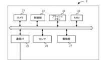
- FIG. 3 is a block diagram showing the configuration of the imaging device 2.
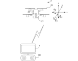
- FIG. 4 is a schematic diagram showing the external appearance of the imaging device 2.
- the imaging device 2 is an aircraft that performs autonomous flight, such as a multirotor helicopter.
- Such an imaging device 2 is called an unmanned aerial vehicle (UAV), an aircraft, a drone, a multicopter, an RPAS (Remote Piloted Aircraft Systems), or an UAS (Unmanned Aircraft Systems), etc.
- UAV unmanned aerial vehicle
- UAV unmanned aerial vehicle
- RPAS Remote Piloted Aircraft Systems
- UAS Unmanned Aircraft Systems
- the photographing device 2 includes a camera 21, a control unit 22, a photographing control unit, a flash memory 23, a RAM 24, a communication I/F 25, a sensor 26, a camera attitude driving unit, and a driving unit 27.
- the control unit 22 has one or more processors such as a CPU, MPU, or DSP, and controls the operation of the image capture device 2.
- the control unit 22 performs various operations by reading a predetermined program stored in a flash memory 23, which is a storage medium, into the RAM 24 and executing it.
- the control unit 22 controls the drive unit 27 to control the position, attitude, speed, etc. of the image capture device 2.
- the control unit 22 controls the camera attitude drive unit to control the relative angle between the camera 21 and the image capture device 2 to an arbitrary angle.
- the image capture control unit also controls the image capture parameters of the camera 21, such as the zoom amount and brightness.
- the control unit 22 transmits image information captured by the camera 21 to the information processing device 1 via the communication I/F 25.
- the sensor 26 may be equipped with a proximity sensor (e.g., a LiDar lidar, a TOF sensor, a laser radar, or a dual camera) for detecting obstacles.
- the proximity sensor may detect obstacles not only in one direction, but in all six directions, i.e., forward, backward, up, down, left and right.
- the control unit 22 may control the drive unit 27 to avoid the obstacle, causing the image capture device 2 to fly autonomously.
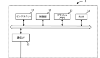
- FIG. 5 is a block diagram showing the configuration of the sensor 3.
- FIG. 6 is a schematic diagram showing how the sensor 3 is attached.
- the sensor 3 includes a sensor unit 31, a control unit 32, a flash memory 33, a RAM 34, and a communication I/F 35.
- the sensor unit 31 has a compass sensor or a position sensor that uses a satellite signal such as GPS.
- the sensor unit 31 is composed of a pair of compass sensors attached to both shoulders of the player as shown in FIG. 6.
- the sensor unit 31 may be a pair of compass sensors attached to the front and back of the player's torso.
- the sensor unit 31 may be a pair of compass sensors attached to each of the player's shoes.
- the sensor unit 31 may also be a combination of these pairs of compass sensors.
- the sensor unit 31 outputs the direction information of each of these pairs of compass sensors as sensing information.
- the sensors worn by the player are not limited to a pair of compass sensors.
- the sensor worn by the player may be a single compass sensor installed on the player's torso (e.g., at the waist).
- the reference direction of the compass sensor corresponds to the direction in which the player is facing.
- the sensor worn by the player may be any sensor capable of sensing the orientation of the body.
- the sensor may be a yaw rate sensor installed at the player's waist and detecting the rotation angle of the player's waist.
- the orientation of the player's torso may be detected by attaching a geomagnetic sensor that detects orientation using geomagnetism to the player's torso.
- the control unit 32 has one or more processors such as a CPU, MPU, or DSP, and controls the operation of the sensor 3.
- the control unit 32 performs various operations by reading out a specific program stored in a flash memory 33, which is a storage medium, into the RAM 34 and executing the program. For example, the control unit 32 acquires sensing information from the sensor unit 31.
- the control unit 32 also transmits the sensing information to the information processing device 1 via the communication I/F 35.
- the control unit 12 of the information processing device 1 determines the movement of the player, including the direction of the player's body, based on the video information received from the image capture device 2 and the sensing information received from the sensor 3.
- FIG. 7 is a functional block diagram of the control unit 12.
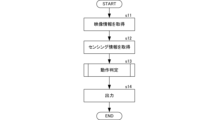
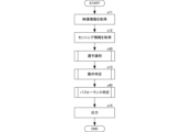
- FIG. 8 is a flowchart showing the operation of the control unit 12.
- the control unit 12 functionally comprises a video information acquisition unit 121, a sensing information acquisition unit 122, an operation determination unit 123, and an output unit 124.
- the video information acquisition unit 121 acquires video information from the filming device 2 (s11).
- the video information includes video captured from above or diagonally above the stadium.
- the sensing information acquisition unit 122 acquires sensing information from the sensor 3 (s12).
- the movement determination unit 123 determines the movement of the player, including the direction of the player's body, based on the acquired video information and sensing information (s13).
- the movement of the player may be determined not only from the direction of the player's body, but also from the speed or acceleration.
- FIG. 9 is a flowchart showing the processing of player movement determination by the movement determination unit 123.
- the movement determination unit 123 recognizes an image of a player from the acquired video information (s131).
- the movement determination unit 123 uses, for example, a deep-learned neural network model as a general object detection algorithm to recognize an image of the field and an image of a player from the acquired video information, and determines the position of the player on the field.
- the motion determination unit 123 may also recognize an image of a player's uniform using a trained neural network model that has previously undergone deep learning of images of the player's uniform.
- FIG. 10(A) is a diagram showing an example of the front of a uniform
- FIG. 10(B) is a diagram showing an example of the back of a uniform.
- the front of the uniform has a player's number and team emblem.
- the back of the uniform has a player's number and name.
- the player's number is placed large in the center of the back of the uniform, and the player's number is placed small on the right side of the front.
- the motion determination unit 123 constructs a trained neural network model by deep learning the arrangement of the player numbers, team emblems, and player names in a predetermined neural network model.
- the motion determination unit 123 inputs the acquired video information to the trained neural network model, and causes it to output the positions of the player images on the field.
- the motion determination unit 123 stores the position information of the player's image within the field in the flash memory 13 (s132). The motion determination unit 123 reads out the past position information stored in the flash memory 13, and determines the speed or acceleration of the player based on the changes in the position information (s133).
- the motion determination unit 123 determines the motion including the direction of the player's body (s134).
- the motion determination unit 123 determines the direction of the player using a trained neural network model that has previously deep-learned the relationship between the image of the player's uniform and the direction of the player. Furthermore, the motion determination unit 123 determines the direction of the player from the sensing information.
- the sensor unit 31 is composed of a pair of compass sensors (first compass sensor and second compass sensor) attached to both shoulders of the player as shown in FIG. 6.
- the pair of compass sensors may be attached to other positions where the direction of the player's body can be determined, such as both hips, the front and back of the torso, or the shoes of both feet.
- the motion determination unit 123 calculates the average value of the direction indicated by the first compass sensor and the direction indicated by the second compass sensor included in the sensing information, and determines the average value as the direction in which the player is facing. The motion determination unit 123 then determines the orientation of the player's body based on the reference orientation of the field and the direction in which the player is facing.
- the reference orientation of the field can be obtained from map information, for example. Alternatively, the reference orientation of the field can be input by the user in advance.
- the motion determination unit 123 determines the average value of the player's body orientation information obtained based on each of the video information and the sensing information as the determination result. Alternatively, the motion determination unit 123 may determine a weighted average of the player's body orientation information obtained based on each of the video information and the sensing information. For example, in sports with fast movements, the accuracy of the player's body orientation information obtained based on video information is high, so the weighting of the player's body orientation information obtained based on video information may be increased. On the other hand, in sports with fast movements, the accuracy of the player's body orientation information obtained based on video information is low, so the weighting of the player's body orientation information obtained based on sensing information may be increased.
- the movement determination unit 123 determines the movement, including the orientation of the player's body, based on the acquired video information and sensing information.
- the output unit 124 outputs the result of the determination by the movement determination unit 123 (s14). For example, the output unit 124 transmits the determination result to another information processing device (an information processing device used by the team's manager or coach). The other information processing device displays the determination result. Alternatively, the output unit 124 may display the determination result on the display 11 of its own device.
- the control unit 12 functionally comprises a display control unit.
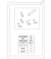
- FIG. 11 is a user interface screen showing an example of the display of the judgment result.
- the judgment result is displayed, for example, as a user interface screen (GUI) of an application program.
- GUI user interface screen
- the GUI includes a field image that imitates a field, player images that imitate players within the field, and movement images that correspond to the movement of the players.
- the judgment result is displayed, for example, as an arrow as shown in FIG. 11.
- the GUI may include a vector display corresponding to the player's speed or acceleration.
- the movement determination system of this embodiment determines the direction of the player's body based on sensing information obtained by sensors worn by the player in addition to video information, so that the direction of the player's body can be determined with high accuracy even in sports where the players move quickly.
- FIG. 12 is a functional block diagram of the control unit 12 according to the modified example 1. Configurations common to FIG. 7 are given the same reference numerals, and descriptions thereof will be omitted.
- FIG. 13 is a flowchart showing the operation of the control unit 12 according to the modified example 1. Processes common to FIG. 8 are given the same reference numerals, and descriptions thereof will be omitted.
- the control unit 12 further includes a player identification unit 125.
- the player identification unit 125 identifies the players appearing in the captured video based on the video information, or based on both the video information and the sensing information (s30).
- FIG. 14 is a flowchart showing the operation of player identification.
- the player identification unit 125 acquires video information of each player (s301).
- the player identification unit 125 recognizes the image of the player from the acquired video information, for example, using a deep-learned neural network model as a general object detection algorithm.
- the player identification unit 125 uses a trained neural network model that has previously undergone deep learning of images of the player's uniform to determine the uniform of the player (s302).
- FIG. 15 is a conceptual diagram showing the results of uniform determination.
- the player identification unit 125 tags the image of each player with the team they belong to, based on the clothing color or team emblem information in the video information, as shown in FIG. 15.
- the player identification unit 125 also uses a trained neural network model that determines player numbers from video information to determine the player numbers (s303).
- Figure 16 is a conceptual diagram showing the results of number determination.
- the player identification unit 125 uses the trained neural network model to tag the images of each player with numbers, as shown in Figure 16.
- the player identification unit 125 determines whether the uniforms and numbers of all players have been determined (s304). If the uniforms and numbers of all players have not been determined, the player identification unit 125 repeats the process from s301.
- the player identification unit 125 When the player identification unit 125 has determined the uniforms and numbers of all players, it identifies the players in the video based on the team to which the player belongs obtained in s302 and the player number obtained in s303 (s305).
- FIG. 17 is a conceptual diagram showing the results of player identification.
- the player identification unit 125 matches the team and number tags of images of the same player from among the team to which the player belongs obtained in Ss02 and the player number obtained in S303, and tags each of the players with identification information.
- the information processing device 1 can determine the individual orientations of multiple players with high accuracy, even in sports such as soccer, which are played by multiple people.
- FIG. 18 is a flowchart showing the operation of another example of player identification.
- the player identification unit 125 in this example identifies the players shown in the captured image based on both the video information and the sensing information.
- a sensor 3 is attached to each of multiple players.
- the player identification unit 125 acquires sensor identification information and sensor position measurement information (s311).
- the sensor identification information is unique identification information (such as a serial number or MAC address) of the sensor 3 attached to each of the multiple players.
- the sensor position measurement information is acquired by the sensor unit 31 of the sensor 3 attached to each of the multiple players.
- the sensor unit 31 has a position sensor such as a GPS.
- the sensor position measurement information can be acquired by a beacon that transmits and receives radio waves, such as Bluetooth (registered trademark). At least three beacons are installed on the field in advance. Each beacon transmits radio waves.
- the sensor unit 31 of the sensor 3 receives radio waves from the beacon and transmits a reply signal in response to the radio waves.
- Each beacon receives the reply signal from the sensor 3.
- Each beacon measures the distance to the sensor 3 based on the time difference between when the radio waves are transmitted and when the reply signal is received.
- the player identification unit 125 acquires distance information to the sensor 3 from the multiple beacons. This allows the player identification unit 125 to uniquely determine the position of the sensor 3 on the field and obtain sensor position measurement information.
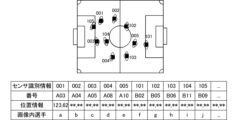
- the player identification unit 125 acquires correspondence information between the players and the worn sensors (s312).
- FIG. 19 is a conceptual diagram showing correspondence information between the players and the worn sensors.
- the correspondence information shows the correspondence between the identification information of the sensor 3 and the team and number information of each player.
- the identification information of the sensor 3 and the team and number information of each player are input in advance by the user when attaching the sensor 3 to each player.
- the player identification unit 125 acquires the sensor position information for each player and adds it to the correspondence information (s313).
- the sensor position information corresponds to the position information within the field as described above. This allows the identification information of the sensor 3 and the sensor position information to be associated with each player.
- the player identification unit 125 uses, for example, a deep-learned neural network model as a general object detection algorithm to recognize images of the field and players from the acquired video information, and determines the position of each recognized player on the field (s314).
- Figure 20 is a conceptual diagram showing the results of determining a position from video.
- the player identification unit 125 attaches an in-image player tag (a-j in the figure) to the image of each player recognized using the trained neural network model, and associates position information with each in-image player tag.
- the player identification unit 125 determines whether the player's position information estimated in the video can be associated with the sensor position information (s315).
- the player identification unit 125 compares the sensor position information obtained in s313 with the position on the field of each player recognized from the video in s314, and associates the two if the distance between the two is within a predetermined value.
- the player identification unit 125 repeats the process from s311 until it determines that the player's position information estimated in the video can be associated with the sensor position information for all players. If the player identification unit 125 determines that the player's position information estimated in the video can be associated with the sensor position information for all players, it identifies the players in the video (s316).
- the information processing device 1 can determine the orientation of each of multiple players with high accuracy, even in sports such as soccer, which are played by multiple people.
- the information processing device 1 of this embodiment can determine the orientation of each of multiple players with high accuracy even when multiple players overlap in the aerial footage.
- FIG. 22 is a flowchart showing the operation of another example of player identification. Processes common to FIG. 18 are given the same reference numerals and will not be described.
- the player identification unit 125 performs uniform determination (s317) if it is determined in s315 that the player's position information estimated in the video cannot be associated with the sensor position information.
- the uniform determination is similar to the process in s302, and is a process of determining the player's uniform using, for example, a trained neural network model that has been deep-trained in advance on images of the player's uniform.
- the player identification unit 125 tags the image of each player with the team they belong to based on the clothing color or team emblem information in the video information.
- the player identification unit 125 identifies the players based on the team they belong to and the uniform determination (s318). For example, when multiple players are crowded together, the sensing information from multiple sensors 3 may overlap, and accurate player identification may not be possible using only the processing using the sensor information from s311 to s314. However, as shown in FIG. 22, the player identification unit 125 can determine sensor identification information corresponding to the player images in the video with high accuracy by combining the processing from s311 to s316 with the uniform determination processing based on the video information from s317 and s318.
- the player identification unit 125 may also identify personal attributes including those of the referee and goalkeeper. Alternatively, the player identification unit 125 may identify substitute players on the bench, coaches, and other related parties. In this way, the information processing device 1 of this embodiment can provide information that identifies the team to which the player belongs, the referee, the goalkeeper, etc. in a competition, and can provide more useful information for more effective coaching of players or competition tactics.
- FIG. 23 is a functional block diagram of the control unit 12 according to the modified example 2. Configurations common to FIG. 12 are given the same reference numerals, and descriptions thereof will be omitted.
- FIG. 24 is a flowchart showing the operation of the control unit 12 according to the modified example 2. Processes common to FIG. 13 are given the same reference numerals, and descriptions thereof will be omitted.
- the control unit 12 further includes a display control unit 126 in addition to the configuration of the first modified example.
- the display control unit 126 displays the player's identification information and body orientation information on the image (s90).
- FIG. 25 is an example of an image displayed on the display 11.
- the display control unit 127 displays, as an example, an image of an arrow corresponding to the body orientation of each player on the image.
- the display control unit 127 also displays, as an example, identification information near each player on the image.
- the display control unit 127 also displays, as an example, an image of an arrow corresponding to the speed or acceleration of each player on the image (however, the image has a different form from the arrow indicating the body orientation).
- the information processing device 1 of variant example 2 can visually provide information on the body orientation determined for each player.
- FIG. 26 is a functional block diagram of the control unit 12 according to the modified example 3. Configurations common to FIG. 12 are given the same reference numerals, and descriptions thereof will be omitted.
- FIG. 27 is a flowchart showing the operation of the control unit 12 according to the modified example 3. Processes common to FIG. 13 are given the same reference numerals, and descriptions thereof will be omitted.
- the control unit 12 further includes an individual performance judgment unit 128.
- the individual performance judgment unit 128 judges the performance of each identified player based on information including the judged body orientation.
- the individual performance includes, for example, the accumulated distance traveled in the competition, top speed, number of sprints, offensive evaluation points, or defensive evaluation points.
- Offensive evaluation points are added for, for example, sprinting in the opposite direction to the body orientation of the defensive player, spending a long time away from the defensive player by a specified distance or more, running into space, creating a passing route, having a fast top speed, high acceleration, a large number of sprints at or above a specified acceleration, a long accumulated running distance, or having the body facing forward toward the offensive side when receiving the ball.
- Defensive points are awarded for, for example, turning the body halfway in relation to the vector direction of the offensive player's speed or acceleration (for example, the angle difference with the offensive player is less than 120 degrees), keeping the distance between other defensive players less than a specified distance, keeping the distance between the offensive player less than a specified distance, being closer to the goal than the offensive players, etc.
- individual performance may be evaluated not only based on the momentary position and body orientation of a player, but also based on time-series information from when the ball is received to when the shot is taken.
- the individual performance assessment unit 128 may generate a probability model of a scoring opportunity based on statistical information on the positions of each player and the ball, and the body orientation of each player in the time-series from when the ball is received to when the shot is taken, and evaluate players based on the probability calculated by the probability model. For example, when the individual performance assessment unit 128 determines that the probability of a scoring opportunity is high based on the probability model, it may lower the evaluation score of the player if the scoring opportunity does not occur. When the individual performance assessment unit 128 determines that the probability of a scoring opportunity is low, it may increase the evaluation score of the player if a scoring opportunity occurs.
- the movement determination system of this embodiment can provide more useful information for more effective coaching of athletes or competition tactics.
- FIG. 28 is a functional block diagram of the control unit 12 according to the fourth modification. Components common to those in FIG. 26 are given the same reference numerals, and descriptions thereof will be omitted.
- FIG. 29 is a flowchart showing the operation of the control unit 12 according to the fourth modification. Processes common to those in FIG. 27 are given the same reference numerals, and descriptions thereof will be omitted.
- the control unit 12 further includes a display control unit 129 in addition to the configuration of the fourth modified example.
- the display control unit 129 displays the identification information of the player and the performance judgment judgment information on the image (s91).
- FIG. 30 is an example of an image displayed on the display 11.
- the display control unit 129 displays, as an example, the identification information of each individual player on the image, and the cumulative movement distance, top speed, number of sprints, offensive evaluation score, defensive evaluation score, and trajectory image as the performance judgment judgment information.
- the information processing device 1 of variant example 4 can visually provide more useful information for more effective coaching of players or competition tactics.
- the offensive team's performance is assessed by determining whether each offensive player is positioned a predetermined distance away from the defensive player (1), whether the difference vector of the velocity or acceleration vector with the defensive player is greater than a predetermined value (2), whether the difference vector with respect to the defensive player's body direction is greater than a predetermined angle (3), whether the velocity or acceleration vector value is greater than a predetermined value (4), etc.
- These predetermined values may be changed depending on the state of the competition. For example, these predetermined values may be set high immediately after the start of the competition, and may be set lower as the competition progresses.
- the judgments of (1) through (8) may be made using arithmetic expressions such as AND and OR.
- the organizational performance assessment unit 1281 determines that an offensive player is unmarked when the assessment values (or values of arithmetic expressions such as AND, OR, etc.) of (1) to (4) above exceed a predetermined value.
- the information processing device 1 of this embodiment can determine whether an offensive player has become unmarked and provide more useful information.
- FIG. 34 is a diagram showing a display example when the organizational performance determination unit 1281 determines that the defensive formation has collapsed.
- the organizational performance determination unit 1281 determines that the organized defensive formation has collapsed when the determination values (5) to (8) above (or the values of the arithmetic expressions such as AND and OR) exceed a predetermined value.
- the display control unit 129 may display on the video the players who are subject to a breakdown in the defensive formation as determined by the organizational performance determination unit 1281, as shown in FIG. 34.
- the display control unit 129 may also highlight the breakdown in the defensive formation as shown in FIG. 34. For example, in the example of FIG. 34, the defensive formation is displayed with dashed lines, and offensive players who deviate from the dashed lines are highlighted.
- the information processing device 1 of this embodiment can determine whether or not the defensive formation has collapsed and provide more useful information.
- FIG. 35 is a diagram showing a display example when the organizational performance determination unit 1281 determines the offensive pass route.
- the organizational performance determination unit 1281 determines the offensive pass route based on the team identification determination of each player, the position and body orientation of the offensive players, and the position of the defensive players.
- the organizational performance determination unit 1281 detects lines connecting offensive players that do not include defensive players as passing routes. Note that the organizational performance determination unit 1281 may exclude lines in the direction of the back of a player who has the ball from passing routes based on the direction in which the body of the player is facing.
- the display control unit 129 may highlight the path course as shown in FIG. 35.
- the information processing device 1 of this embodiment can determine the offensive pass route and provide more useful information.
- FIG. 36 is a diagram showing a display example in which the organizational performance determination unit 1281 detects spaces into which the offensive players should run.
- the organizational performance determination unit 1281 detects spaces into which the offensive players should run based on the team identification determination of each player and the positions and body orientations of multiple defensive players.
- the organizational performance determination unit 1281 determines an area that is more than a predetermined distance away from a defensive player as a space into which a player should run. Note that the organizational performance determination unit 1281 may determine the space behind the defensive player as a space into which a player should run preferentially, based on the direction in which the player's body is facing. Furthermore, the display control unit 129 may highlight the player or position related to the space, as shown in FIG. 36.
- the information processing device 1 of this embodiment detects the space into which the offensive team should run and can provide more useful information.
- organizational performance can be evaluated not only based on the momentary positions and body orientations of players, but also based on chronological information from when the ball is received to when the shot is taken.
- organizational performance may be evaluated based on the duration of time during which it is determined that a missed mark or a space has occurred. For example, the evaluation may be different depending on whether the duration during which it is determined that a missed mark or a space has occurred is 1 second or 5 seconds.
- individual performance or organized offense may be evaluated based on the timing of when a player becomes unmarked or when space is created. For example, an offensive player who becomes unmarked when a crossing pass event occurs or when a final pass event occurs in front of a goal may be rated higher, and an offensive player who becomes unmarked at a time other than when these events occur may be rated relatively lower.
- FIG. 37 is a functional block diagram of the control unit 12 according to the modified example 6. Configurations common to FIG. 31 are given the same reference numerals, and descriptions thereof will be omitted.
- FIG. 38 is a flowchart showing the operation of the control unit 12 according to the modified example 6. Processes common to FIG. 32 are given the same reference numerals, and descriptions thereof will be omitted.
- the control unit 12 according to the sixth modification includes a tag processing unit 220.
- the tag processing unit 220 performs tagging processing to accept tagging input from a user for video information that corresponds to a noteworthy play among video information (S61). That is, the information processing device 1 according to the sixth modification accepts manual tagging input for a video when a user such as a coach judges it to be a noteworthy play.
- the tag includes, for example, time information from the start of the game. Alternatively, the tag may include additional information such as player information, area information, and whether the player is near or far from the ball. The tag is recorded for each player and stored in the flash memory 23.
- the tag processing unit 220 may automatically tag the video of a play that is judged by the organizational performance judgment unit 1281 to have been lost from its marker or broken in formation, a pass route, or space in S61.
- tagging is automatically performed on the video of a play that is lost from its marker or broken in formation, a pass route, or space, making it easier for players, coaches, managers, etc. to analyze notable plays when reviewing them later.
- FIG. 39 is a diagram showing a display example when other judgments are made.
- the offside line is displayed as a dashed line.
- the offside line is made up of the second defensive player from the defensive team's own goal, including the goalkeeper.
- the defensive players that make up the offside line are highlighted.
- line connections between all players are displayed. For example, all offensive players are connected with solid lines.
- all defensive players are connected with dashed lines. This makes it easier for coaches and other related parties to recognize distance relationships or the presence or absence of passing routes. In particular, when acquiring video information taken diagonally from above, players often do not overlap, so by displaying the teammate's line surrounding a specific player as a triangle or more, coaches and other related parties can easily recognize the support distance of a specific player.
- FIG. 40(A) is a schematic diagram of an imaging device 2A that is supported by multiple physical lines (wires, etc.) and can be moved to any position in two-dimensional (planar) or three-dimensional space.
- the movement determination system of this embodiment can be realized even with this type of imaging device 2A.
- FIG. 40(B) is a schematic diagram of an imaging device 2B that is supported by rails and can be moved to any position on the rails.
- the movement determination system of this embodiment can be realized even with this type of imaging device 2B.
- the imaging device 2 may also be a fixed camera rather than a movable camera.
- FIG. 41 is a block diagram showing the overall configuration of a motion determination system according to an application example. Components common to Figure 1 are given the same reference numerals, and descriptions thereof will be omitted.
- the motion determination system of FIG. 41 includes a server 5.
- the motion determination system also includes multiple information processing devices 1.
- the server 5 performs various operations in place of the information processing devices 1 described in FIG. 1 to FIG. 40.
- the first information processing device 1 to which the controller unit 101 is connected is used by a user who operates the image capture device 2 (for example, a user who provides the motion determination system of this embodiment as a business).
- the other second information processing device 1 is used by related parties such as coaches.
- the second information processing device 1 includes the tag processing unit 220 shown in variant example 6, and accepts tagging input from related parties such as coaches.
- the server 5, multiple information processing devices 1, and sensor 3 are connected via a network such as the Internet or a LAN.
- the server 5 includes a video information acquisition unit 121, a sensing information acquisition unit 122, a movement determination unit 123, and an output unit 124.
- the server 5 acquires sensing information from the sensor 3, and acquires video information captured by the image capture device 2 from the information processing device 1 of the user who operates the image capture device 2.
- the server 5 determines the movement of the player, including the direction of the body, and outputs the determination result to the information processing device 1 used by the coach or other related person.
- the information processing device 1 used by the coach or other related person executes an application program of the movement determination system of this embodiment, and displays the determination result by the application program.
- the server 5 has the main function and realizes the movement judgment system of this embodiment. Therefore, the information processing device 1 used by the relevant parties such as coaches only needs to mainly transmit and receive information and perform display processing. Therefore, the information processing device 1 does not need to have advanced processing functions and storage capacity.
- soccer was shown as an example of a sport.
- the motion determination system of this embodiment can also be applied to other sports, such as rugby, American football, hockey, basketball, yacht racing, windsurfing, etc.
- FIGS. 42 and 43 are diagrams showing examples of displays when the motion judgment system of this embodiment is applied to yacht racing or windsurfing.
- FIG. 42 is an example of displaying on an image the direction of the sail of a yacht or windsurfing, the vector of the yacht or windsurfing board, the wind vector, or performance judgment information, etc.
- FIG. 43 is an example of displaying on an image imitating a yacht or windsurfing, the identification information of the yacht or windsurfing athlete, the direction of the sail of a yacht or windsurfing, the vector of the yacht or windsurfing, the wind vector, or other information such as performance judgment.
- the competition venue is the sea, and image information is acquired by photographing the sea from the sky or from diagonally above.
- the sensor may be attached to the athlete, or to the sail of the yacht or windsurfing.
- the orientation of the athlete's body corresponds to the orientation of the sail.
- the sensing information may also include information on wind direction and wind strength.
- the wind direction may be determined from the wave shape of the water surface reflected in the image, or may be measured by attaching a sensor to the imaging device 2.
- the performance of a yacht or windsurfing race may be evaluated by calculating an evaluation score, for example, by determining whether the sails are oriented in a way that generates maximum thrust based on the wind direction relative to the direction of travel to the finish line.
- the motion determination system of this embodiment can be applied not only to team sports, but also to individual sports such as snowboarding or skiing.
- Figure 44(A) is a schematic plan view of a snowboard.
- the sensor 3 may be attached to the athlete, or may be attached to the front or back of the snowboard as shown in Figure 44(A).
- the orientation of the athlete's body corresponds to the orientation of the snowboard.
- Figure 44(B) is a schematic plan view of a ski.
- the sensor 3 may be attached to the athlete, or may be attached to the front or back of the ski as shown in Figure 44(B).
- the orientation of the athlete's body corresponds to the orientation of the ski.
- the sensor 3 may include an air pressure sensor.
- the sensor 3 may be attached to the boot and sense the pressure of the athlete's feet against the board.
- the performance may be determined by the jump height based on the sensor 3.
- the motion determination system may consider the period when the pressure attached to the board is zero as the jump time and estimate the jump height based on the air pressure.
- the motion determination system may determine the horizontal direction based on the video information and estimate the height of the filming device 2 at the time when the highest point is shot as the jump height.
- the motion determination system may estimate the rotation angle of the board based on the video information and the sensing information.
- the motion determination system may perform a performance evaluation of a snowboard or ski jumping event (half pipe, slope style, big air, etc.) based on the jump height and rotation angle.
- the motion determination system may also superimpose the jump height, rotation angle, and evaluation score on the captured video.
Landscapes
- Health & Medical Sciences (AREA)
- General Health & Medical Sciences (AREA)
- Physical Education & Sports Medicine (AREA)
- Image Analysis (AREA)
Priority Applications (2)
| Application Number | Priority Date | Filing Date | Title |
|---|---|---|---|
| PCT/JP2023/032171 WO2025052496A1 (ja) | 2023-09-04 | 2023-09-04 | 動作判定システム、動作判定方法、およびプログラム |
| JP2025543955A JPWO2025052496A1 (https=) | 2023-09-04 | 2023-09-04 |
Applications Claiming Priority (1)
| Application Number | Priority Date | Filing Date | Title |
|---|---|---|---|
| PCT/JP2023/032171 WO2025052496A1 (ja) | 2023-09-04 | 2023-09-04 | 動作判定システム、動作判定方法、およびプログラム |
Publications (1)
| Publication Number | Publication Date |
|---|---|
| WO2025052496A1 true WO2025052496A1 (ja) | 2025-03-13 |
Family
ID=94923226
Family Applications (1)
| Application Number | Title | Priority Date | Filing Date |
|---|---|---|---|
| PCT/JP2023/032171 Pending WO2025052496A1 (ja) | 2023-09-04 | 2023-09-04 | 動作判定システム、動作判定方法、およびプログラム |
Country Status (2)
| Country | Link |
|---|---|
| JP (1) | JPWO2025052496A1 (https=) |
| WO (1) | WO2025052496A1 (https=) |
Citations (5)
| Publication number | Priority date | Publication date | Assignee | Title |
|---|---|---|---|---|
| JP2009219633A (ja) * | 2008-03-14 | 2009-10-01 | Yamaha Corp | 運動支援装置および運動支援プログラム |
| JP2015536710A (ja) * | 2012-10-25 | 2015-12-24 | ナイキ イノベイト シーブイ | チームスポーツ環境におけるアスレチックパフォーマンスをモニタするシステムと方法 |
| JP2021128691A (ja) * | 2020-02-17 | 2021-09-02 | Kddi株式会社 | マルチモーダル行動認識方法、装置およびプログラム |
| WO2022019001A1 (ja) * | 2020-07-20 | 2022-01-27 | 国立大学法人大阪大学 | 評価装置、評価方法及びプログラム |
| WO2023140039A1 (ja) * | 2022-01-21 | 2023-07-27 | ソニーグループ株式会社 | 情報処理装置、情報処理方法、プログラム、情報分析システム |
-
2023
- 2023-09-04 WO PCT/JP2023/032171 patent/WO2025052496A1/ja active Pending
- 2023-09-04 JP JP2025543955A patent/JPWO2025052496A1/ja active Pending
Patent Citations (5)
| Publication number | Priority date | Publication date | Assignee | Title |
|---|---|---|---|---|
| JP2009219633A (ja) * | 2008-03-14 | 2009-10-01 | Yamaha Corp | 運動支援装置および運動支援プログラム |
| JP2015536710A (ja) * | 2012-10-25 | 2015-12-24 | ナイキ イノベイト シーブイ | チームスポーツ環境におけるアスレチックパフォーマンスをモニタするシステムと方法 |
| JP2021128691A (ja) * | 2020-02-17 | 2021-09-02 | Kddi株式会社 | マルチモーダル行動認識方法、装置およびプログラム |
| WO2022019001A1 (ja) * | 2020-07-20 | 2022-01-27 | 国立大学法人大阪大学 | 評価装置、評価方法及びプログラム |
| WO2023140039A1 (ja) * | 2022-01-21 | 2023-07-27 | ソニーグループ株式会社 | 情報処理装置、情報処理方法、プログラム、情報分析システム |
Also Published As
| Publication number | Publication date |
|---|---|
| JPWO2025052496A1 (https=) | 2025-03-13 |
Similar Documents
| Publication | Publication Date | Title |
|---|---|---|
| US12443186B2 (en) | Fitness and sports applications for an autonomous unmanned aerial vehicle | |
| JP7538816B2 (ja) | 自律的な活動監視方法、プログラムおよびシステム | |
| Delmerico et al. | Are we ready for autonomous drone racing? the UZH-FPV drone racing dataset | |
| US12478851B2 (en) | Tennis self-training system | |
| CN101964047B (zh) | 一种基于多跟踪点的人体动作识别方法 | |
| CN110114735B (zh) | 由无人自主交通工具捕捉比赛的图像 | |
| AU2018273557B2 (en) | Systems and methods for tracking and controlling a mobile camera to image objects of interest | |
| CN108141512B (zh) | 飞行装置、移动装置、电子设备以及计算机可读存储介质 | |
| CN105224070B (zh) | 体育活动平视显示器系统和方法 | |
| CN105080111B (zh) | 运动球运动监测方法和系统 | |
| CN113599788B (zh) | 用于在体育事件中监测运动员表现的系统和方法 | |
| WO2019050916A1 (en) | TECHNIQUES FOR RENDERING THREE-DIMENSIONAL ANIMATED GRAPHICS FROM A VIDEO | |
| US12440746B2 (en) | Kinematic analysis of user form | |
| WO2000031560A9 (en) | Multiple object tracking system | |
| JP2011517979A (ja) | 実環境におけるイベントをシミュレートするためのシステム | |
| US11132005B2 (en) | Unmanned aerial vehicle escape system, unmanned aerial vehicle escape method, and program | |
| KR102519798B1 (ko) | 라이다센서 및 인공지능을 이용한 체험형 야구-시뮬레이션 서비스 시스템 | |
| JP7054950B1 (ja) | 位置計測システム、及び位置計測方法 | |
| WO2025052496A1 (ja) | 動作判定システム、動作判定方法、およびプログラム | |
| US12343612B2 (en) | Automated offside detection and visualization for sports | |
| EP4080466B1 (en) | Ball position identification system, ball position identification method, and program | |
| JP7580660B2 (ja) | ゴルフ支援システム、サーバ装置、ゴルフ支援方法、および、ゴルフ支援プログラム | |
| WO2010025294A1 (en) | Position determination systems and methods for use in sporting and recreational activities | |
| CN120235908A (zh) | 一种击球效果评估方法、装置、系统、电子设备以及存储介质 | |
| NZ756949B2 (en) | Systems and methods for tracking and controlling a mobile camera to image objects of interest |
Legal Events
| Date | Code | Title | Description |
|---|---|---|---|
| 121 | Ep: the epo has been informed by wipo that ep was designated in this application |
Ref document number: 23951401 Country of ref document: EP Kind code of ref document: A1 |
|
| ENP | Entry into the national phase |
Ref document number: 2025543955 Country of ref document: JP Kind code of ref document: A |