WO2025047232A1 - 測定装置、測定方法及びプログラム - Google Patents
測定装置、測定方法及びプログラム Download PDFInfo
- Publication number
- WO2025047232A1 WO2025047232A1 PCT/JP2024/026677 JP2024026677W WO2025047232A1 WO 2025047232 A1 WO2025047232 A1 WO 2025047232A1 JP 2024026677 W JP2024026677 W JP 2024026677W WO 2025047232 A1 WO2025047232 A1 WO 2025047232A1
- Authority
- WO
- WIPO (PCT)
- Prior art keywords
- cross
- control unit
- moving means
- measuring device
- groove
- Prior art date
- Legal status (The legal status is an assumption and is not a legal conclusion. Google has not performed a legal analysis and makes no representation as to the accuracy of the status listed.)
- Ceased
Links
Images


Classifications
-
- B—PERFORMING OPERATIONS; TRANSPORTING
- B60—VEHICLES IN GENERAL
- B60C—VEHICLE TYRES; TYRE INFLATION; TYRE CHANGING; CONNECTING VALVES TO INFLATABLE ELASTIC BODIES IN GENERAL; DEVICES OR ARRANGEMENTS RELATED TO TYRES
- B60C11/00—Tyre tread bands; Tread patterns; Anti-skid inserts
- B60C11/24—Wear-indicating arrangements
-
- B—PERFORMING OPERATIONS; TRANSPORTING
- B60—VEHICLES IN GENERAL
- B60C—VEHICLE TYRES; TYRE INFLATION; TYRE CHANGING; CONNECTING VALVES TO INFLATABLE ELASTIC BODIES IN GENERAL; DEVICES OR ARRANGEMENTS RELATED TO TYRES
- B60C19/00—Tyre parts or constructions not otherwise provided for
-
- G—PHYSICS
- G01—MEASURING; TESTING
- G01B—MEASURING LENGTH, THICKNESS OR SIMILAR LINEAR DIMENSIONS; MEASURING ANGLES; MEASURING AREAS; MEASURING IRREGULARITIES OF SURFACES OR CONTOURS
- G01B11/00—Measuring arrangements characterised by the use of optical techniques
- G01B11/22—Measuring arrangements characterised by the use of optical techniques for measuring depth
-
- G—PHYSICS
- G01—MEASURING; TESTING
- G01M—TESTING STATIC OR DYNAMIC BALANCE OF MACHINES OR STRUCTURES; TESTING OF STRUCTURES OR APPARATUS, NOT OTHERWISE PROVIDED FOR
- G01M17/00—Testing of vehicles
- G01M17/007—Wheeled or endless-tracked vehicles
- G01M17/02—Tyres
Definitions
- This disclosure relates to a measurement device, a measurement method, and a program.
- the purpose of this disclosure is to improve technology for measuring the remaining tread depth of vehicles, including tires.
- a measuring device that detects at least one mark on the surface of the grooves of a tire of a means of transportation from an image of the means of transportation including tires, and includes a control unit that calculates the remaining groove depth of the means of transportation based on the detected mark.
- the control unit generates, based on the image, at least one cross-sectional profile indicating an outline of a cross section of the moving means at a position where the mark is detected.
- control unit generates a plurality of cross-sectional profiles at different positions in the width direction as the at least one cross-sectional profile.
- the control unit determines at least one of the number and spacing of the multiple cross-sectional profiles to be generated based on characteristic information indicating characteristics of the moving means.
- a computer-implemented measurement method comprising: Detecting a mark provided on a surface of a groove of the moving means from an image of the moving means; Calculating a remaining groove depth of the moving means based on the detected mark;
- a measurement method including:
- One embodiment of the present disclosure makes it possible to improve technology for measuring the remaining tread depth of a vehicle, including tires.
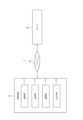
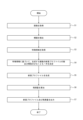
- FIG. 1 is a schematic diagram showing a configuration of a measurement system. 4 is a flowchart showing an operation performed by the measurement device.
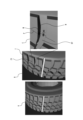
- FIG. 13 is a diagram showing an example of an image input to the measuring device.
- FIG. 13 is a diagram for explaining detection of a marker.
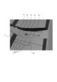
- FIG. 13 is a diagram for explaining generation of a cross-sectional profile.
- FIG. 13 is a diagram showing an example of a cross-sectional profile.
- FIG. 1 shows an example of the configuration of a measurement system 1 according to one embodiment.
- the measurement system 1 includes a measurement device 10 and a camera 20.
- the measurement device 10 and the camera 20 are connected via a network 30, wirelessly, wired, or a combination of wireless and wired.
- the measurement device 10 and the camera 20 may be integrated into one unit.
- the camera 20 may be a 3D camera using a stereo system, a ToF (Time of Flight) system, or the like.
- the camera 20 can transmit images of tires as a means of transportation to the measuring device 10 via the network 30.
- Network 30 includes the Internet, at least one Wide Area Network (WAN), at least one Metropolitan Area Network (MAN), or a combination thereof.
- Network 30 may also include at least one wireless network, at least one wired network, at least one optical network, or a combination thereof.
- the measuring device 10 detects the mark M on the surface of the groove of the moving means from an image of the moving means including the tire.
- the measuring device 10 calculates the remaining tread depth of the moving means based on the detected mark M.
- the measuring device 10 acquires an image of the moving means by receiving it from the camera 20.
- the moving means includes tires and crawlers.
- the moving means is a tire.
- the tire includes tires for vehicles, motorcycles, bicycles, airplanes, etc.
- the tire may be an OR (Off The Road) tire mounted on a construction vehicle, mining vehicle, etc.
- the surface of the groove is the groove wall W, but is not limited to this, and the surface of the groove includes the bottom BT of the groove.
- the remaining tread depth may be the groove depth or the remaining tread volume.
- the remaining tread depth is reduced as the tire is worn down through use.
- the remaining tread depth can be calculated only from the image of the moving means without the need for an operator to actually measure the remaining tread depth by hand. It is now possible to obtain the remaining tread depth of a vehicle such as a tire at low cost and easily, compared to measuring it manually. This makes it possible to improve the technology for measuring the remaining tread depth of a vehicle including tires.
- the measuring device 10 includes a control unit 11, a memory unit 12, a communication unit 13, and an input/output unit 14.
- the memory unit 12 includes at least one semiconductor memory, at least one magnetic memory, at least one optical memory, or a combination of at least two of these.
- the semiconductor memory is, for example, a random access memory (RAM) or a read only memory (ROM).
- the RAM is, for example, a static random access memory (SRAM) or a dynamic random access memory (DRAM).
- the ROM is, for example, an electrically erasable programmable read only memory (EEPROM).
- the memory unit 12 functions, for example, as a main memory device, an auxiliary memory device, or a cache memory.
- the memory unit 12 stores any information, control/processing programs, etc. used in the operation of the measuring device 10, and information obtained by the operation of the measuring device 10.
- the communication unit 13 includes at least one communication interface.
- the communication interface is, for example, a LAN interface, an interface compatible with mobile communication standards such as the 4G (4th Generation) standard or the 5G (5th Generation) standard, an interface compatible with short-range wireless communication such as Bluetooth (registered trademark), or a LAN interface.
- the communication unit 13 receives information used in the operation of the measuring device 10, and transmits information obtained by the operation of the measuring device 10.
- the input/output unit 14 includes at least one input/output interface.
- the input/output interface includes a touch screen that is integrated with a display.
- the input/output unit 14 accepts an operation to input information used in the operation of the measuring device 10, and outputs information obtained by the operation of the measuring device 10.
- the input/output unit 14 may be connected to the measuring device 10 as an external input device. Any connection method may be used, such as a Universal Serial Bus (USB).
- USB Universal Serial Bus
- the input/output unit 14 may not be integrated and may be composed of separate input and output units.
- the input unit includes at least one input interface, such as a physical key or a microphone.
- the output unit includes at least one output interface, such as a display or a speaker.
- the operation of the measuring device 10 will be described with reference to Figures 2 to 6. This description of the operation corresponds to the measurement method executed by the measuring device 10.
- step S1 the control unit 11 acquires an image of the moving means.
- the image is an image showing the surface of the moving means that is in contact with the ground.
- the image may be a two-dimensional image or a three-dimensional image.
- a three-dimensional image may be an image in which information indicating depth is added to RGB values (an RGBD image).
- the control unit 11 acquires an image captured by the camera 20 by receiving it from the camera 20.
- step S2 the control unit 11 detects the sign M provided on the wall W of the groove of the moving means from the acquired image. Any method may be used to detect the sign M. In this example, the control unit 11 detects the sign M from the image using any image analysis technology. For example, the control unit 11 may obtain a trained model for detecting the sign M from an image, generated by machine learning, and detect the sign M using the trained model. The control unit 11 may detect the sign M based on the RGB values, HSV values, or brightness values of each pixel of the two-dimensional image.
- FIG. 3 shows an example of a three-dimensional image acquired by the control unit 11 in step S1.
- the control unit 11 detects a sign M provided at a portion indicated by Z1 in FIG. 3.
- the sign M in FIG. 3 has a star shape as an example, but the shape of the sign M is not limited to this.
- the control unit 11 may detect a marker MB provided on the bottom BT of the groove, which is the surface of the groove.
- the control unit 11 detects a marker MB provided at the portion indicated by Z2 in FIG. 3.
- the marker MB in FIG. 3 has an elliptical shape as an example, but the shape of the marker MB is not limited to this.
- the marker MB may be formed by a protrusion protruding from the bottom BT or a recess carved into the bottom BT.
- a and B of Figure 4 show examples of three-dimensional images acquired in step S1
- C of Figure 4 shows examples of a marker M on the wall W of the groove of tire T and a marker MB on the bottom BT of the groove, detected from the portion indicated by Z3 in image B.
- the white arrows in A and B of Figure 4 indicate the width direction of tire T.
- the dashed line in C of Figure 4 shows an example of a cross-sectional profile P generated in step S5 below.
- the marker M may be related to the groove depth. This allows the remaining groove amount to be calculated more accurately, as described below.
- the marker M is two parallel straight lines provided on the wall W of the groove as shown in FIG. 4C, but the marker M may also directly indicate the remaining groove amount, such as a scale in which the bottom BT of the groove is 0 and the numbers increase toward the surface of the tire T.
- the control unit 11 may output the number indicated by the marker M, or a value corresponding to the number, as the remaining groove amount in step S6.
- the marker M may have a different symbol or color depending on the remaining groove amount.
- the marker M may be formed by a protrusion protruding from the wall W or a recess carved into the wall W.
- step S3 the control unit 11 acquires characteristic information indicating the characteristics of the means of transportation.
- the characteristic information includes any information indicating the characteristics of the tire T, such as the diameter, width direction length, type, shape, etc. of the tire T.
- the control unit 11 may analyze the type of tire, etc. based on the image acquired in step S1 using any image analysis technology, and acquire this as characteristic information.
- step S4 the control unit 11 determines at least one of the number and interval of the multiple cross-sectional profiles P to be generated based on the characteristic information indicating the characteristics of the means of transportation.
- the control unit 11 reads information that previously associates the tire characteristics indicated by the characteristic information with the number or interval of the cross-sectional profiles P from the storage unit 12, and determines at least one of the number and interval of the cross-sectional profiles P based on the information.
- the control unit 11 determines that the interval of the cross-sectional profiles P to be generated is X millimeters and the number of profiles is Y. For example, the control unit 11 may determine that the number of cross-sectional profiles P is greater the wider the tire as the means of transportation indicated by the characteristic information is. The control unit 11 may directly receive a value indicating the number or interval of the cross-sectional profiles from the user via the input/output unit 14.
- the control unit 11 may, for example, determine to generate multiple arbitrary cross-sectional profiles P at predetermined intervals in different directions in the width direction of the tire T from the position of the detected marker M.
- the control unit 11 may, for example, read information indicating the number of cross-sectional profiles P to be generated per unit length of the marker M from the storage unit 12, and determine to generate that number of cross-sectional profiles P.
- step S5 the control unit 11 generates a cross-sectional profile P that indicates the outline of the cross section of the moving means at the position where the marker M was detected. This allows the use of a cross-sectional profile with a small amount of data, enabling efficient analysis of changes in the remaining groove amount.
- the control unit 11 generates the cross-sectional profile P using any image processing technique.
- the cross-sectional profile P is point cloud data or mesh data. If the image acquired in step S1 is a two-dimensional image, the control unit 11 may generate point cloud data using photogrammetry or the like.
- the control unit 11 generates a cross-sectional profile P having a plane perpendicular to a straight line L along the width direction of the tire T, the number and interval of which are determined in step S4.
- the control unit 11 may generate a line profile as the cross-sectional profile P by extracting the point cloud data on the plane as a continuous line.
- FIG. 5 shows the position of the marker M detected in step S2 and the straight line L along the width direction of the tire T.
- the control unit 11 generates cross-sectional profiles P1 to P5 at a predetermined interval I in different directions in the width direction of the tire T from the position of the marker M detected in C of FIG. 4.
- Each of the cross-sectional profiles P1 to P5 has a plane P51 perpendicular to the straight line L along the width direction of the tire T.
- the plane P51 in FIG. 5 represents a part of the plane of the cross-sectional profile P.
- Cross-sectional profiles P1 to P5 in FIG. 5 show a portion of each contour of the cross-sectional profile P.
- the control unit 11 may generate the cross-sectional profile P based on the position of the marker MB instead of or in addition to the marker M.
- control unit 11 may generate an approximate plane or approximate curved surface from the surface of the tire T shown in the image using any image processing technique, and then generate a cross-sectional profile P having a plane perpendicular to the approximate plane.
- the control unit 11 may generate cross-sectional profiles P in areas of the point cloud data or mesh data where there is little or no loss.
- the control unit 11 may determine that there is no loss in that the density of the point cloud data is equal to or greater than a predetermined value.
- the control unit 11 may increase the number of cross-sectional profiles P in the width direction to be generated up to areas where there is no loss in the point cloud data or mesh data, regardless of the number determined in step S4.
- control unit 11 generates multiple cross-sectional profiles at different widthwise positions of the tire T as at least one cross-sectional profile. This makes it easy to combine multiple cross-sectional profiles to reconstruct them three-dimensionally for analysis and interpretation.
- step S6 the control unit 11 calculates the remaining groove amount.
- the control unit 11 calculates the remaining groove amount based on the generated cross-sectional profile P.
- the control unit 11 calculates the remaining groove amount from the cross-sectional profile P using any image analysis technique.
- the control unit 11 may detect the baseline of the concave and convex portions of the cross-sectional profile P, and calculate the peak-to-peak difference between the concave and convex portions as the remaining groove amount based on the baseline.
- the control unit 11 may represent the cross-sectional profile P using coordinate axes of the tire radius and deflection angle by polar coordinate conversion, and calculate the peak-to-peak difference between the concave and convex portions as the remaining groove amount.
- the control unit 11 may calculate the groove depth as the remaining groove amount for each cross-sectional profile P, or may calculate the average value of the groove remaining amounts of the multiple cross-sectional profiles P generated as the remaining groove amount.
- the unit of the groove depth as the remaining groove amount may be centimeters, millimeters, etc.
- the control unit 11 may calculate the volume of the groove as the remaining groove amount when the lines corresponding to the recesses in the radially inward direction of the tire of the multiple cross-sectional profiles P are connected to form a three-dimensional groove shape.
- the unit of the volume of the remaining groove amount may be cubic centimeters, etc.
- Figure 6 is a diagram showing an example of the overall configuration of the cross-sectional profile P1 generated by the control unit 11. Z3 in Figure 6 partially enlarges the cross-sectional profile P1, and the groove depth RTD as the remaining groove amount calculated by the control unit 11 is indicated by a double-ended arrow.
- the control unit 11 may calculate the remaining groove amount by reading information indicating the remaining groove amount from the memory unit 12 by associating the color or shape with the groove depth. For example, if the marker M is a marker indicating the groove depth with numbers or scale lines and is provided in parallel at different radial positions on the tire, as in the marker M shown in Figure 5, the control unit 11 may detect the value of the marker M provided in the radially outward direction from the image and calculate it as the remaining groove amount.
- step S7 the control unit 11 outputs the cross-sectional profile P and the calculated remaining groove amount.
- the control unit 11 outputs the cross-sectional profile P generated in step S5 and the remaining groove amount calculated in step S6 via the input/output unit 14. This notifies the user of the cross-sectional profile P and the remaining groove amount. Thereafter, the processing operation of the control unit 11 ends.
- a computer capable of executing program instructions may be used to function as the above-described measuring device 10.
- the computer may be a general purpose computer, a special purpose computer, a workstation, a personal computer (PC), an electronic notepad, etc.
- the program instructions may be program code, code segments, etc., for performing the necessary tasks.
- the computer includes a processor, a memory unit, an input unit, an output unit, and a communication unit.
- the processor may be a CPU, an MPU, a GPU, a DSP (Digital Signal Processor), a SoC (System on a Chip), etc., and may be composed of multiple processors of the same or different types.
- the processor reads out a program from the memory unit and executes it to control each of the above components and perform various arithmetic processing. At least a part of the processing content may be realized by hardware.
- the input unit is an input interface that receives a user's input operation and obtains information based on the user's operation, and is a pointing device, keyboard, microphone, etc.
- the output unit is an output interface that outputs information, and is a display, speaker, etc.
- the communication unit is a communication interface for communicating with an external device, and is, for example, a LAN interface.
- the SDGs have been proposed to realize a sustainable society.
- One embodiment of the present invention is considered to be a technology that can contribute to goals such as "No. 9 - Build a foundation for industry and technological innovation,” “No. 12 - responsible consumption and production,” and “No. 13 - Take concrete measures against climate change.”
- Control unit 12 Storage unit 13 Communication unit 14 Input/output unit 20 Camera 30 Network
Landscapes
- Engineering & Computer Science (AREA)
- Mechanical Engineering (AREA)
- Physics & Mathematics (AREA)
- General Physics & Mathematics (AREA)
- Length Measuring Devices By Optical Means (AREA)
Abstract
測定装置10は、タイヤを含む移動手段が撮像された画像から、前記移動手段の溝の表面に設けられた少なくとも一つの標識を検出し、検出した前記標識に基づいて前記移動手段の残溝量を算出する制御部11を備える。
Description
本開示は、測定装置、測定方法及びプログラムに関する。
従来、タイヤの摩耗度を良好かつ確実に認識するために、タイヤ表面に設けられた溝の溝壁面に凹部を設け、当該凹部内に光輝性材料を付着させるものが知られている(例えば特許文献1参照)。
従来技術では、人間が目で摩耗度を認識する、あるいは専用の計測器で測定する必要があるため、工数がかかる。また、タイヤが巨大化すると目で確認できない場合もある。また、局所的な部分の溝の残溝深さ(RTD: Remained Tread Depth)のレベルしか把握できず、広域の精確な数字は把握できない。さらに、目で判断する、あるいは専用の計測器で測定する場合には車を止める必要がある。このように、タイヤの残溝量を測定する技術には改善の余地があった。
かかる事情に鑑みてなされた本開示の目的は、タイヤを含む移動手段の残溝量を測定する技術を改善することにある。
上記課題を解決するための本開示の要旨は、以下のとおりである。
(1)タイヤを含む移動手段が撮像された画像から、前記移動手段タイヤの溝の表面に設けられた少なくとも一つの標識を検出し、検出した前記標識に基づいて前記移動手段の残溝量を算出する制御部を備える、測定装置。
(2)上記(1)に記載の測定装置であって、前記標識は前記溝の深さに関連する標識である、測定装置。
(3)上記(1)又は(2)に記載の測定装置であって、
前記制御部は、前記画像に基づいて、前記標識が検出された位置における、前記移動手段の断面の輪郭を示す少なくとも1つの断面プロファイルを生成する、測定装置。
前記制御部は、前記画像に基づいて、前記標識が検出された位置における、前記移動手段の断面の輪郭を示す少なくとも1つの断面プロファイルを生成する、測定装置。
(4)上記(3)に記載の測定装置であって、前記断面プロファイルは、前記タイヤの幅方向に沿った直線に垂直な平面を有する、測定装置。
(5)上記(3)又は(4)に記載の測定装置であって、前記制御部は、前記少なくとも1つの断面プロファイルとして、互いに異なる前記幅方向の位置における、複数の断面プロファイルを生成する、測定装置。
(6)上記(5)に記載の測定装置であって、
前記制御部は、前記移動手段の特徴を示す特徴情報に基づいて、生成する前記複数の断面プロファイルの数及び間隔の少なくとも一方を決定する、測定装置。
前記制御部は、前記移動手段の特徴を示す特徴情報に基づいて、生成する前記複数の断面プロファイルの数及び間隔の少なくとも一方を決定する、測定装置。
(7)コンピュータが実行する測定方法であって、
移動手段が撮像された画像から、前記移動手段の溝の表面に設けられた標識を検出することと、
検出した前記標識に基づいて前記移動手段の残溝量を算出することと、
を含む、測定方法。
移動手段が撮像された画像から、前記移動手段の溝の表面に設けられた標識を検出することと、
検出した前記標識に基づいて前記移動手段の残溝量を算出することと、
を含む、測定方法。
(8)コンピュータを、上記(1)から(6)のいずれかに記載の測定装置として機能させるためのプログラム。
本開示の一実施形態によれば、タイヤを含む移動手段の残溝量を測定する技術を改善することが可能となる。
以下、一実施形態について、図面を参照して詳細に説明する。
図1に、一実施形態に係る測定システム1の構成例を示す。測定システム1は、測定装置10と、カメラ20とを備える。測定装置10とカメラ20とはネットワーク30を介して、無線、有線、又は、無線及び有線の組み合わせにより接続される。測定装置10とカメラ20とは、一体の構成となっていてもよい。
カメラ20は、ステレオ方式、ToF(Time of Flight)方式などの3Dカメラであってもよい。カメラ20は、移動手段としてのタイヤを撮像した画像をネットワーク30を介して測定装置10へ送信可能である。
ネットワーク30は、インターネット、少なくとも1つのWAN(Wide Area Network)、少なくとも1つのMAN(Metropolitan Area Network)、又はこれらの組み合わせを含む。ネットワーク30は、少なくとも1つの無線ネットワーク、少なくとも1つの有線ネットワーク、少なくとも1つの光ネットワーク、又はこれらの組み合わせを含んでもよい。
測定装置10は、タイヤを含む移動手段が撮像された画像から、移動手段の溝の表面に設けられた標識Mを検出する。測定装置10は、検出した標識Mに基づいて移動手段の残溝量を算出する。本実施形態では、測定装置10は、移動手段を撮像した画像をカメラ20から受信することで取得する。移動手段はタイヤの他、クローラを含む。本実施形態において、移動手段はタイヤである。タイヤは車両用、バイク用、自転車用、又は飛行機用等のものを含む。タイヤは、建設車両、鉱山車両などに装着されるOR(Off The Road)タイヤであってもよい。本実施形態において、溝の表面は溝の壁Wであるが、これに限られず、溝の表面は溝の底BTを含む。残溝量は、溝深さであってもよいし、残溝体積であってもよい。タイヤが使用により摩耗されることにより、残溝量は低減する。本実施形態によれば、実際に作業員が手で残溝量を測定する必要なく、移動手段の画像のみから残溝量を算出することができる。タイヤ等の移動手段の残溝量を、人手で測定する場合と比較して、低コストかつ簡便に取得することが可能となる。よって、タイヤを含む移動手段の残溝量を測定する技術を改善することが可能となる。
<測定装置10>
測定装置10は、制御部11、記憶部12、通信部13、及び入出力部14を備える。
測定装置10は、制御部11、記憶部12、通信部13、及び入出力部14を備える。
制御部11には、少なくとも1つのプロセッサ、少なくとも1つの専用回路又はこれらの組み合わせを含む。プロセッサは、CPU(Central Processing Unit)若しくはGPU(Graphics Processing Unit)等の汎用プロセッサ又は特定の処理に特化した専用プロセッサである。専用回路は、例えば、FPGA(Field-Programmable Gate Array)又はASIC(Application Specific Integrated Circuit)である。制御部11は測定装置10の各部を制御しながら、測定装置10の動作に関わる処理を実行する。
記憶部12には、少なくとも1つの半導体メモリ、少なくとも1つの磁気メモリ、少なくとも1つの光メモリ又はこれらのうち少なくとも2種類の組み合わせが含まれる。半導体メモリは例えばRAM(random access memory)又はROM(read only memory)である。RAMは例えばSRAM(static random access memory)又はDRAM(dynamic random access memory)である。ROMは例えばEEPROM(electrically erasable programmable read only memory)である。記憶部12は例えば主記憶装置、補助記憶装置又はキャッシュメモリとして機能する。記憶部12には測定装置10の動作に用いられる任意の情報、制御・処理プログラム等と、測定装置10の動作によって得られた情報とが記憶される。
通信部13には、少なくとも1つの通信用インタフェースが含まれる。通信用インタフェースは、例えば、LANインタフェース、4G(4th Generation)規格、若しくは5G(5th Generation)規格等の移動通信規格に対応したインタフェース、Bluetooth(登録商標)等の近距離無線通信に対応したインタフェース、又はLANインタフェースである。通信部13は、測定装置10の動作に用いられる情報を受信し、また測定装置10の動作によって得られる情報を送信する。
入出力部14には、少なくとも1つの入出力用インタフェースが含まれる。入出力用インタフェースは、ディスプレイと一体的に設けられたタッチスクリーンを含む。入出力部14は、測定装置10の動作に用いられる情報を入力する操作を受け付け、測定装置10の動作によって得られる情報を出力する。入出力部14は、測定装置10に備えられる代わりに、外部の入力機器として測定装置10に接続されてもよい。接続方式は、例えば、USB(Universal Serial Bus)等の任意の方式を用いることができる。入出力部14は、一体化されずに、別個の入力部と出力部とにより構成されてもよい。この場合、入力部には、物理キー又はマイク等の少なくとも1つの入力用インタフェースが含まれる。出力部には、ディスプレイ又はスピーカ等の少なくとも1つの出力用インタフェースが含まれる。
図2から図6を参照して、測定装置10の動作を説明する。本動作の説明は、測定装置10が実行する測定方法に相当する。
ステップS1において、制御部11は、移動手段が撮像された画像を取得する。該画像は、移動手段の接地面である表面が映った画像である。画像は二次元の画像であってもよいし、三次元の画像であってもよい。三次元の画像は、RGB値に奥行きを示す情報を付加されたもの(RGBD画像)であってもよい。本例では制御部11は、カメラ20によって撮像された画像を、カメラ20から受信することで取得する。
ステップS2において、制御部11は、取得した画像から、移動手段の溝の壁Wに設けられた標識Mを検出する。標識Mの検出には任意の手法が採用されてよい。本例では制御部11は、任意の画像解析技術により画像から標識Mを検出する。例えば制御部11は、機械学習により生成された、画像から標識Mを検出する学習済モデルを取得し、該学習済モデルを用いて標識Mを検出してもよい。制御部11は、二次元の画像の各画素のRGB値、HSV値、又は輝度値等に基づいて、標識Mを検出してもよい。
図3は、ステップS1で制御部11が取得した三次元の画像の例を示す。例えば制御部11は図3のZ1で示す部分に設けられた標識Mを検出する。図3における標識Mは、一例として星型の形状を有するが、標識Mの形状はこれに限られない。
制御部11は、溝の壁Wに設けられた標識Mに代えて又は加えて、溝の表面としての溝の底BTに設けられた標識MBを検出してもよい。例えば制御部11は、図3のZ2で示す部分に設けられた標識MBを検出する。図3における標識MBは、一例として楕円型の形状を有するが、標識MBの形状はこれに限られない。標識MBは、底BTから盛り上がった凸部または底BTに刻まれた凹部により形成されてもよい。
図4のAとBは、ステップS1で取得した三次元の画像の例を示し、図4のCは、Bの画像のZ3で示す部分から検出された、タイヤTの溝の壁Wに設けられた標識Mと、溝の底BTに設けられた標識MBとの例を示す。図4のAとBとにおける白抜き矢印は、タイヤTの幅方向を示す。図4のCの破線は、以下のステップS5で生成される断面プロファイルPの例を示す。
標識Mは、溝深さに関連するものであってもよい。これにより、以下で説明するように、残溝量をより精度よく算出することが可能となる。本例における標識Mは、図4のCに示すように、溝の壁W上に設けられた平行な二本の直線であるが、標識Mは例えば、溝の底BTを0として、タイヤTの表面に向かうに従い増加する数字とともに表現される目盛り等、残溝量を直接的に示すものであってもよい。この場合制御部11は、標識Mが示す数字、又は該数字に対応する値を、ステップS6において残溝量として出力してもよい。標識Mは、残溝量に応じて記号又は色等が異なるものであってもよい。標識Mは、壁Wから盛り上がった凸部または壁Wに刻まれた凹部により形成されてもよい。
ステップS3において、制御部11は、移動手段の特徴を示す特徴情報を取得する。本例では、特徴情報は、タイヤTの直径、幅方向の長さ、種類、形等の、タイヤTの特徴を示す任意の情報を含む。制御部11は、任意の画像解析技術により、ステップS1で取得した画像に基づいてタイヤの種類等を解析し、特徴情報として取得してもよい。
ステップS4において、制御部11は、移動手段の特徴を示す特徴情報に基づいて、生成する複数の断面プロファイルPの数及び間隔の少なくとも一方を決定する。これにより、例えば幅方向の距離が長いタイヤは自動的に断面プロファイルを多く生成することが可能となり、様々な種類の移動手段に応じた断面プロファイルを用いた残溝量の解析を効率化できる。例えば制御部11は、特徴情報が示すタイヤの特徴と、断面プロファイルPの数又は間隔を予め対応付けた情報を記憶部12から読出し、当該情報に基づいて断面プロファイルPの数及び間隔の少なくとも一方を決定する。例えば該情報が、タイヤの種類Aに対応付けて、断面プロファイルPの間隔をXミリメートル、断面プロファイルをY枚と示す場合、制御部11は、生成する断面プロファイルPの間隔をXミリメートル、枚数をY枚とすることを決定する。例えば制御部11は、特徴情報が示す移動手段としてのタイヤの幅が広い程、断面プロファイルPの枚数を多く決定してもよい。制御部11は、入出力部14を介して、ユーザから直接、断面プロファイルの枚数又は間隔を示す値を受け付けてもよい。
制御部11は例えば、検出した標識Mの位置から、タイヤTの幅方向であって互いに異なる方向に所定の間隔で、任意の複数の断面プロファイルPを生成することを決定してもよい。制御部11は例えば、標識Mの単位長さあたりに生成する断面プロファイルPの枚数を示す情報を記憶部12から読出し、当該枚数の断面プロファイルPを生成することを決定してもよい。
ステップS5において、制御部11は、標識Mが検出された位置における、移動手段の断面の輪郭を示す断面プロファイルPを生成する。これにより、データ量の少ない断面プロファイルを用いることができ、効率的な溝残量の変化の解析が可能となる。制御部11は、任意の画像処理技術を用いて断面プロファイルPを生成する。本例では断面プロファイルPは点群データ又はメッシュデータである。制御部11は、ステップS1で取得した画像が二次元の画像である場合、フォトグラメトリ等により点群データを生成してもよい。
本例では制御部11は、ステップS4で決定した数及び間隔の断面プロファイルPであって、タイヤTの幅方向に沿った直線Lに垂直な平面を有する断面プロファイルPを生成する。これにより、以下で説明するように、幅方向で互いに異なる位置の断面プロファイルを複数生成した場合に、当該複数の断面プロファイルを並べて、残溝量の変化を解析し、移動手段の表面の摩耗の傾向を把握することが容易となる。例えば制御部11は、該平面上の点群データを連続した線として抽出したラインプロファイルを、断面プロファイルPとして生成してもよい。図5に、ステップS2で検出した標識Mの位置と、タイヤTの幅方向に沿った直線Lとを示す。図5に示すように、制御部11は、図4のCで検出された標識Mの位置から、タイヤTの幅方向であって互いに異なる方向に所定の間隔Iで、断面プロファイルP1からP5を生成する。断面プロファイルP1からP5は、タイヤTの幅方向に沿った直線Lに垂直な平面P51をそれぞれ有する。図5の平面P51は、断面プロファイルPの平面の一部を表す。図5の断面プロファイルP1からP5は、断面プロファイルPのそれぞれの輪郭の一部を示す。制御部11は、標識Mに代えて又は加えて、標識MBの位置に基づいて断面プロファイルPを生成してもよい。
これに限られず、制御部11は、画像が示すタイヤTの表面から、任意の画像処理技術により近似平面、又は近似曲面を生成した後、該近似平面に垂直な平面を有する断面プロファイルPを生成してもよい。
制御部11は、ステップS1で取得した三次元の画像が点群データ又はメッシュデータである場合に、該点群データ又はメッシュデータの欠損の程度が低い、又は欠損が無い領域において、断面プロファイルPを生成してもよい。制御部11は、該点群データの密度が所定値以上である欠損が無いと判断してもよい。制御部11は、ステップS4で決定した枚数に関わらず、点群データ又はメッシュデータの欠損がない領域まで、生成する断面プロファイルPの幅方向の数を増やしてもよい。
このようにして制御部11は、少なくとも1つの断面プロファイルとして、タイヤTの互いに異なる幅方向の位置における、複数の断面プロファイルを生成する。これにより、例えば複数の断面プロファイルを組み合わせて立体的に再構成し、分析及び解析することが容易となる。
ステップS6において、制御部11は、残溝量を算出する。本実施形態では、制御部11は、生成した断面プロファイルPに基づいて残溝量を算出する。制御部11は、任意の画像解析技術を用いて断面プロファイルPから残溝量を算出する。例えば制御部11は、断面プロファイルPの凹部と凸部とのベースラインを検出し、該ベースラインに基づいて凹部と凸部とのピーク・ツー・ピークの差分量を残溝量として算出してもよい。例えば制御部11は、極座標変換により、断面プロファイルPをタイヤの半径と偏角との座標軸を用いて表し、凹部と凸部とのピーク・ツー・ピークの差分量を残溝量として算出してもよい。
制御部11は、断面プロファイルPごとに残溝量としての溝の深さを算出してもよいし、生成した複数の断面プロファイルPのそれぞれの溝残量の平均値を、溝残量として算出してもよい。残溝量としての溝の深さの単位はセンチメートル、ミリメートル等であってもよい。制御部11は、複数の断面プロファイルPを生成した場合、該複数の断面プロファイルPのタイヤの径内側方向の凹部に相当する線が連結して立体的な溝の形状を成すとき、当該溝の体積を残溝量として算出してもよい。残溝量の体積の単位は立法センチメートル等の単位であってもよい。図6は、制御部11が生成した断面プロファイルP1の全体の構成例を示す図である。図6のZ3は、断面プロファイルP1を部分的に拡大し、制御部11が算出する残溝量としての溝の深さRTDを、両端矢印で示す。
これに限られず、残溝量の算出には任意の手法が採用されてよい。例えば標識Mが溝の深さに関連する色又は形状等を有する標識である場合、制御部11は、当該色又は形と、溝の深さとを対応付けて残溝量を示す情報を記憶部12から読出すことで残溝量を算出してもよい。例えば標識Mが溝の深さを数字又は目盛り線で示す標識であり、図5で示す標識Mのように、タイヤの径方向の異なる位置に平行に設けられている場合に、制御部11は、径外側方向に設けられている標識Mの値を画像から検出して、残溝量として算出してもよい。
ステップS7において、制御部11は、断面プロファイルP及び算出した残溝量を出力する。本実施形態では、制御部11は、ステップS5で生成した断面プロファイルP及びステップS6で算出した残溝量を入出力部14を介して出力する。これにより、ユーザに対し断面プロファイルP及び残溝量が通知される。その後、制御部11の処理の動作は終了する。
<プログラム>
上述した測定装置10として機能させるために、プログラム命令を実行可能なコンピュータを用いることも可能である。ここで、コンピュータは、汎用コンピュータ、専用コンピュータ、ワークステーション、PC(Personal Computer)、電子ノートパッドなどであってもよい。プログラム命令は、必要なタスクを実行するためのプログラムコード、コードセグメントなどであってもよい。
上述した測定装置10として機能させるために、プログラム命令を実行可能なコンピュータを用いることも可能である。ここで、コンピュータは、汎用コンピュータ、専用コンピュータ、ワークステーション、PC(Personal Computer)、電子ノートパッドなどであってもよい。プログラム命令は、必要なタスクを実行するためのプログラムコード、コードセグメントなどであってもよい。
コンピュータは、プロセッサと、記憶部と、入力部と、出力部と、通信部と、を備える。プロセッサは、CPU、MPU、GPU、DSP(Digital Signal Processor)、SoC(System on a Chip)などであり、同種又は異種の複数のプロセッサにより構成されてもよい。プロセッサは、記憶部からプログラムを読み出して実行することで、上記各構成の制御及び各種の演算処理を行う。なお、これらの処理内容の少なくとも一部をハードウェアで実現することとしてもよい。入力部は、ユーザの入力操作を受け付けてユーザの操作に基づく情報を取得する入力インタフェースであり、ポインティングデバイス、キーボード、マイクなどである。出力部は、情報を出力する出力インタフェースであり、ディスプレイ、スピーカなどである。通信部は、外部の装置と通信するための通信インタフェースであり、例えばLANインタフェースである。
プログラムは、コンピュータが読み取り可能な記録媒体に記録されていてもよい。このような記録媒体を用いれば、プログラムをコンピュータにインストールすることが可能である。ここで、プログラムが記録された記録媒体は、非一過性(non-transitory)の記録媒体であってもよい。非一過性の記録媒体は、特に限定されるものではないが、例えば、CD-ROM、DVD-ROM、USB(Universal Serial Bus)メモリなどであってもよい。また、このプログラムは、ネットワークを介して外部装置からダウンロードされる形態としてもよい。
上述の実施形態は代表的な例として説明したが、本開示の趣旨及び範囲内で、多くの変更及び置換ができることは当業者に明らかである。したがって、本開示は、上述の実施形態によって制限するものと解するべきではなく、請求の範囲から逸脱することなく、種々の変形又は変更が可能である。例えば、実施形態の構成図に記載の複数の構成ブロックを統合したり、1つの構成ブロックを分割したりすることが可能である。また、実施形態のフローチャートに記載の複数のステップを1つに統合したり、1つのステップを分割したりすることが可能である。
持続可能な社会の実現に向けて、SDGsが提唱されている。本発明の一実施形態は「No.9_産業と技術革新の基盤を作ろう」および「No.12_つくる責任、つかう責任」および「No.13_気候変動に具体的な対策を」などに貢献する技術となり得ると考えられる。
10 測定装置
11 制御部
12 記憶部
13 通信部
14 入出力部
20 カメラ
30 ネットワーク
11 制御部
12 記憶部
13 通信部
14 入出力部
20 カメラ
30 ネットワーク
Claims (8)
- タイヤを含む移動手段が撮像された画像から、前記移動手段の溝の表面に設けられた少なくとも一つの標識を検出し、
検出した前記標識に基づいて前記移動手段の残溝量を算出する制御部を備える、測定装置。 - 請求項1に記載の測定装置であって、
前記標識は前記溝の深さに関連する標識である、測定装置。 - 請求項1又は2に記載の測定装置であって、
前記制御部は、前記画像に基づいて、前記標識が検出された位置における、前記移動手段の断面の輪郭を示す少なくとも1つの断面プロファイルを生成する、測定装置。 - 請求項3に記載の測定装置であって、
前記断面プロファイルは、前記タイヤの幅方向に沿った直線に垂直な平面を有する、測定装置。 - 請求項4に記載の測定装置であって、
前記制御部は、前記少なくとも1つの断面プロファイルとして、互いに異なる前記幅方向の位置における、複数の断面プロファイルを生成する、測定装置。 - 請求項5に記載の測定装置であって、
前記制御部は、前記移動手段の特徴を示す特徴情報に基づいて、生成する前記複数の断面プロファイルの数及び間隔の少なくとも一方を決定する、測定装置。 - コンピュータが実行する測定方法であって、
移動手段が撮像された画像から、前記移動手段の溝の表面に設けられた標識を検出することと、
検出した前記標識に基づいて前記移動手段の残溝量を算出することと、
を含む、測定方法。 - コンピュータを、請求項1又は2に記載の測定装置として機能させるためのプログラム。
Applications Claiming Priority (2)
| Application Number | Priority Date | Filing Date | Title |
|---|---|---|---|
| JP2023139260 | 2023-08-29 | ||
| JP2023-139260 | 2023-08-29 |
Publications (1)
| Publication Number | Publication Date |
|---|---|
| WO2025047232A1 true WO2025047232A1 (ja) | 2025-03-06 |
Family
ID=94818987
Family Applications (1)
| Application Number | Title | Priority Date | Filing Date |
|---|---|---|---|
| PCT/JP2024/026677 Ceased WO2025047232A1 (ja) | 2023-08-29 | 2024-07-25 | 測定装置、測定方法及びプログラム |
Country Status (1)
| Country | Link |
|---|---|
| WO (1) | WO2025047232A1 (ja) |
Citations (4)
| Publication number | Priority date | Publication date | Assignee | Title |
|---|---|---|---|---|
| JPH07174528A (ja) * | 1993-12-20 | 1995-07-14 | Yokohama Rubber Co Ltd:The | タイヤ断面形状測定方法 |
| JP2014137291A (ja) * | 2013-01-17 | 2014-07-28 | Bridgestone Corp | 外観画像生成方法及び外観画像生成装置 |
| JP2021063702A (ja) * | 2019-10-11 | 2021-04-22 | 横浜ゴム株式会社 | タイヤ摩耗度特定装置、タイヤ摩耗度特定方法及びプログラム |
| JP2021063703A (ja) * | 2019-10-11 | 2021-04-22 | 横浜ゴム株式会社 | タイヤ摩耗度推定装置、タイヤ摩耗度学習装置、タイヤ摩耗度推定方法、学習済モデルの生成方法及びプログラム |
-
2024
- 2024-07-25 WO PCT/JP2024/026677 patent/WO2025047232A1/ja not_active Ceased
Patent Citations (4)
| Publication number | Priority date | Publication date | Assignee | Title |
|---|---|---|---|---|
| JPH07174528A (ja) * | 1993-12-20 | 1995-07-14 | Yokohama Rubber Co Ltd:The | タイヤ断面形状測定方法 |
| JP2014137291A (ja) * | 2013-01-17 | 2014-07-28 | Bridgestone Corp | 外観画像生成方法及び外観画像生成装置 |
| JP2021063702A (ja) * | 2019-10-11 | 2021-04-22 | 横浜ゴム株式会社 | タイヤ摩耗度特定装置、タイヤ摩耗度特定方法及びプログラム |
| JP2021063703A (ja) * | 2019-10-11 | 2021-04-22 | 横浜ゴム株式会社 | タイヤ摩耗度推定装置、タイヤ摩耗度学習装置、タイヤ摩耗度推定方法、学習済モデルの生成方法及びプログラム |
Similar Documents
| Publication | Publication Date | Title |
|---|---|---|
| US10311835B1 (en) | Method for detection and estimation of tire tread wear | |
| JP6454109B2 (ja) | 路面状態管理装置及び路面状態管理プログラム | |
| JP5625376B2 (ja) | 耐摩耗性能評価装置及び耐摩耗性能評価方法、並びに耐摩耗性能評価用コンピュータプログラム | |
| US10210411B2 (en) | Method and apparatus for establishing feature prediction accuracy | |
| CN110942460B (zh) | 一种轮胎花纹深度测量方法、系统及存储介质 | |
| JP7485011B2 (ja) | 道路劣化診断装置、道路劣化診断システム、道路劣化診断方法、及び、プログラム | |
| CN113543990B (zh) | 周向主沟槽检测方法和周向主沟槽检测装置 | |
| US20220254062A1 (en) | Method, device and storage medium for road slope predicating | |
| JP2015207281A (ja) | 立体物検出装置、立体物検出方法、立体物検出プログラム、及び移動体機器制御システム | |
| CN105300401A (zh) | 电子装置及其控制方法 | |
| CN117218301B (zh) | 基于多通道立体视觉的电梯曳引轮轮槽重建方法及系统 | |
| US20210146839A1 (en) | Method and apparatus with three-dimensional object display | |
| US10955333B2 (en) | System and method for calculating margin of friction coefficient at tire contact patch | |
| CN117433440A (zh) | 一种基于激光点云的巷道形变实时检测方法、装置及存储介质 | |
| CN116981955A (zh) | 旋转传感器的对象检测 | |
| CN105082888A (zh) | 一种轮胎胎纹侦测装置 | |
| TW201527141A (zh) | 輪胎胎紋偵測裝置 | |
| AU2023414534A1 (en) | Tire wear monitoring device and tire wear monitoring method | |
| WO2025069815A1 (ja) | ゴム製品及び測定方法 | |
| JP2025025553A (ja) | 破面率算出方法、情報処理装置、及びプログラム | |
| US20260103033A1 (en) | Tire external-scratch monitoring device, tire external-scratch monitoring method, and program | |
| JP2003149256A5 (ja) | ||
| CA3268185A1 (en) | Tire external-scratch monitoring device, tire external-scratch monitoring method, and program | |
| JP7217570B1 (ja) | 情報処理システム及びプログラム、情報処理方法、サーバ | |
| US20260104377A1 (en) | Tire outer-damage monitoring device, and tire outer-damage monitoring method |
Legal Events
| Date | Code | Title | Description |
|---|---|---|---|
| 121 | Ep: the epo has been informed by wipo that ep was designated in this application |
Ref document number: 24859274 Country of ref document: EP Kind code of ref document: A1 |
|
| NENP | Non-entry into the national phase |
Ref country code: DE |