WO2025047113A1 - 方位計測装置 - Google Patents
方位計測装置 Download PDFInfo
- Publication number
- WO2025047113A1 WO2025047113A1 PCT/JP2024/024079 JP2024024079W WO2025047113A1 WO 2025047113 A1 WO2025047113 A1 WO 2025047113A1 JP 2024024079 W JP2024024079 W JP 2024024079W WO 2025047113 A1 WO2025047113 A1 WO 2025047113A1
- Authority
- WO
- WIPO (PCT)
- Prior art keywords
- angular velocity
- rotation
- velocity sensor
- axis
- detection axis
- Prior art date
- Legal status (The legal status is an assumption and is not a legal conclusion. Google has not performed a legal analysis and makes no representation as to the accuracy of the status listed.)
- Pending
Links
Images


Classifications
-
- G—PHYSICS
- G01—MEASURING; TESTING
- G01C—MEASURING DISTANCES, LEVELS OR BEARINGS; SURVEYING; NAVIGATION; GYROSCOPIC INSTRUMENTS; PHOTOGRAMMETRY OR VIDEOGRAMMETRY
- G01C19/00—Gyroscopes; Turn-sensitive devices using vibrating masses; Turn-sensitive devices without moving masses; Measuring angular rate using gyroscopic effects
-
- G—PHYSICS
- G01—MEASURING; TESTING
- G01C—MEASURING DISTANCES, LEVELS OR BEARINGS; SURVEYING; NAVIGATION; GYROSCOPIC INSTRUMENTS; PHOTOGRAMMETRY OR VIDEOGRAMMETRY
- G01C17/00—Compasses; Devices for ascertaining true or magnetic north for navigation or surveying purposes
- G01C17/02—Magnetic compasses
- G01C17/28—Electromagnetic compasses
-
- G—PHYSICS
- G01—MEASURING; TESTING
- G01C—MEASURING DISTANCES, LEVELS OR BEARINGS; SURVEYING; NAVIGATION; GYROSCOPIC INSTRUMENTS; PHOTOGRAMMETRY OR VIDEOGRAMMETRY
- G01C17/00—Compasses; Devices for ascertaining true or magnetic north for navigation or surveying purposes
- G01C17/38—Testing, calibrating, or compensating of compasses
-
- G—PHYSICS
- G01—MEASURING; TESTING
- G01C—MEASURING DISTANCES, LEVELS OR BEARINGS; SURVEYING; NAVIGATION; GYROSCOPIC INSTRUMENTS; PHOTOGRAMMETRY OR VIDEOGRAMMETRY
- G01C19/00—Gyroscopes; Turn-sensitive devices using vibrating masses; Turn-sensitive devices without moving masses; Measuring angular rate using gyroscopic effects
- G01C19/02—Rotary gyroscopes
- G01C19/34—Rotary gyroscopes for indicating a direction in the horizontal plane, e.g. directional gyroscopes
- G01C19/38—Rotary gyroscopes for indicating a direction in the horizontal plane, e.g. directional gyroscopes with north-seeking action by other than magnetic means, e.g. gyrocompasses using earth's rotation
-
- G—PHYSICS
- G01—MEASURING; TESTING
- G01C—MEASURING DISTANCES, LEVELS OR BEARINGS; SURVEYING; NAVIGATION; GYROSCOPIC INSTRUMENTS; PHOTOGRAMMETRY OR VIDEOGRAMMETRY
- G01C25/00—Manufacturing, calibrating, cleaning, or repairing instruments or devices referred to in the other groups of this subclass
- G01C25/005—Manufacturing, calibrating, cleaning, or repairing instruments or devices referred to in the other groups of this subclass initial alignment, calibration or starting-up of inertial devices
Definitions
- the present invention relates to a direction measuring device.
- Non-Patent Document 1 discloses an orientation measurement device and an orientation measurement method that include a measurement unit in which an angular velocity sensor having a detection axis in a horizontal plane rotates around a vertical axis on a rotation mechanism to detect the angular velocity associated with the rotation of the Earth, plots the rotation angle of the detection axis of the angular velocity sensor on the horizontal axis of a graph and the measurement results of the angular velocity on the vertical axis, and calculates the orientation by performing sine function fitting on the plotted waveform.
- Non-Patent Document 1 if the azimuth measurement device rotates around the vertical axis while measuring the azimuth, the rotation angle of the detection axis of the angular velocity sensor may deviate from the reference value, making it impossible to accurately calculate the azimuth.
- the present invention was made in consideration of these circumstances, and aims to provide a direction measurement device that can improve direction measurement accuracy.
- a direction measuring device includes a first angular velocity sensor having a first detection axis extending along the horizontal direction and detecting a first angular velocity about the first detection axis as a center of rotation, a rotation mechanism having a rotation axis extending along the vertical direction and rotating the first detection axis of the first angular velocity sensor about the rotation axis as a center of rotation, and a second angular velocity sensor used to correct the rotation angle of the first detection axis in the rotation mechanism, the second angular velocity sensor having a second detection axis extending along the vertical direction and detecting a second angular velocity about the second detection axis as a center of rotation.
- the present invention provides a direction measurement device that can improve direction measurement accuracy.
- FIG. 1 is a schematic diagram showing a configuration of a direction measuring device according to a first embodiment.
- FIG. 2 is a plan view showing the measurement unit.
- FIG. 2 is a diagram illustrating an example of a physical configuration of a control unit.
- FIG. 2 is a plan view showing the measurement unit rotated around a vertical axis.
- 11 is a graph showing a first angular velocity with respect to a rotation angle before correction.
- 11 is a graph showing a first angular velocity with respect to a corrected rotation angle.
- FIG. 11 is a schematic diagram showing the configuration of a direction measuring device according to a second embodiment.
- an orthogonal coordinate system consisting of the X-axis, Y-axis, and Z-axis may be attached to each drawing for convenience.
- the X-axis, Y-axis, and Z-axis correspond to each other in each drawing.
- the direction parallel to the X-axis is the "X-axis direction”
- the direction parallel to the Y-axis is the "Y-axis direction”
- the direction parallel to the Z-axis is the "Z-axis direction”.
- the direction of the tip of the arrows on the X-axis, Y-axis, and Z-axis is "positive” or “+ (plus)", and the direction opposite the arrows is “negative” or "- (minus)”.
- the plane defined by the X-axis and Y-axis is the "XY plane”, and the same applies to planes defined by the other axes.
- the Z-axis direction is an example of the "vertical direction”
- the direction along the XY plane is an example of the "horizontal direction”.
- Figure 1 is a schematic diagram showing the configuration of a direction measuring device according to the first embodiment.
- Figure 2 is a plan view showing a measurement unit.
- the orientation measurement device 1 measures orientation by measuring the angular velocity of the Earth's rotation.
- the orientation measurement device 1 is, for example, a north-finding device that finds true north.
- the orientation measurement device 1 includes a measurement unit 10 and a control unit 20.
- the measurement unit 10 measures the rotational angular velocity of the Earth. As shown in FIG. 1, the measurement unit 10 includes a first angular velocity sensor 11, a second angular velocity sensor 12, a rotation mechanism 13, and a sensor housing 19.
- the first angular velocity sensor 11 has a first detection axis 11D extending along the horizontal direction (XY plane) and detects a first angular velocity about the first detection axis 11D as a rotation center.
- the first angular velocity sensor 11 is, for example, a MEMS (Micro Electro Mechanical Systems) gyro sensor, but is not limited to this as long as it can detect angular velocity.
- the first angular velocity when the measurement unit 10 is stationary corresponds to the component about the first detection axis 11D as a rotation center among the horizontal components of the angular velocity of the earth's rotation at the measurement point latitude. In other words, the magnitude of the first angular velocity changes based on the azimuth angle of the first detection axis 11D.
- the latitude ⁇ is constant
- the first angular velocity ⁇ is maximum.
- the first angular velocity ⁇ is zero.
- the first angular velocity ⁇ can be expressed as a sine function with the azimuth angle ⁇ of the first detection axis 11D as a variable.
- the rotation mechanism 13 has a rotation axis 13R that extends along the vertical direction (Z-axis), and rotates the first detection axis 11D of the first angular velocity sensor 11 around the rotation axis 13R as the center of rotation.
- the angle that the first detection axis 11D rotated by the rotation mechanism 13 makes with the reference direction RD in the XY plane is defined as the rotation angle ⁇ of the first detection axis 11D.
- the rotation mechanism 13 is a rotating table, and the first angular velocity sensor 11 is fixed onto the table surface of the rotation mechanism 13.
- the rotation angle ⁇ is measured by a rotary encoder 13A.
- the rotary encoder 13A is provided, for example, in the rotation mechanism 13, but may also be provided outside the rotation mechanism 13.
- the second angular velocity sensor 12 is used to correct the rotation angle ⁇ of the first detection axis 11D in the rotation mechanism 13.
- the first angular velocity sensor 11 rotates together with the rotation mechanism 13 and the rotary encoder 13A.
- the rotation angle of the first detection axis 11D deviates from the rotation angle ⁇ measured by the rotary encoder 13A.
- the second angular velocity sensor 12 is used to correct the rotation angle ⁇ , which is the measurement value of the rotary encoder 13A, to obtain the true rotation angle.
- the second angular velocity sensor 12 is, like the first angular velocity sensor 11, for example, but is not limited to, a MEMS gyro sensor.
- the second angular velocity sensor 12 has a second detection axis 12D extending along the vertical direction (Z-axis) and detects a second angular velocity about the second detection axis 12D as the center of rotation.
- the second angular velocity is the angular velocity when the measurement unit 10 rotates around the vertical axis due to an external impact or the like.
- the angular deviation of the orientation of the measurement unit 10 from the reference direction RD can be calculated based on the rotation angle calculated by integrating the measured value of the second angular velocity measured by the second angular velocity sensor 12. This makes it possible to correct the rotation angle ⁇ based on the second angular velocity.
- the second angular velocity sensor 12 is provided away from the rotation mechanism 13. In this case, the second angular velocity sensor 12 detects only the angular velocity around the vertical axis of the measurement unit 10. However, the second angular velocity sensor may be provided in the rotation mechanism, like the first angular velocity sensor. In this case, the second angular velocity sensor detects a composite angular velocity of the angular velocity of the rotation mechanism and the angular velocity of the measurement unit around the vertical axis. For this reason, the angular velocity of the measurement unit is calculated, for example, by subtracting the angular velocity detected when the measurement unit is stationary from the detection result of the second angular velocity sensor. The angular velocity of the measurement unit may also be calculated by subtracting the set angular velocity of the rotation mechanism from the detection result of the second angular velocity sensor.
- the sensor housing 19 houses the first angular velocity sensor 11, the second angular velocity sensor 12, and the rotation mechanism 13. Although not shown, the sensor housing 19 may include a communication module that enables the first angular velocity sensor 11, the second angular velocity sensor 12, and the rotation mechanism 13 to communicate with the control unit 20.
- the control unit 20 controls the measurement unit 10 and measures the direction based on the measurement results of the measurement unit 10. As shown in FIG. 1, the control unit 20 is connected to the measurement unit 10 so as to be able to communicate with it.
- the control unit 20 includes a drive unit 21, an acquisition unit 22, a calculation unit 23, and a correction unit 24.
- the drive unit 21 drives the rotation mechanism 13.
- the acquisition unit 22 acquires the first angular velocity from the first angular velocity sensor 11, acquires the second angular velocity from the second angular velocity sensor 12, and acquires the rotation angle ⁇ from the rotary encoder 13A.
- the calculation unit 23 plots the first angular velocity against the rotation angle ⁇ and calculates the direction by fitting this plot with a sine function. Since the first angular velocity is maximum when the first detection axis 11D faces due north, the calculation unit 23 may calculate due north from the rotation angle ⁇ at which the first angular velocity is maximum, without fitting with a sine function.
- the correction unit 24 corrects the rotation angle ⁇ of the first detection axis 11D of the rotation mechanism 13 based on the second angular velocity.
- the correction unit 24, for example, corrects the rotation angle ⁇ after it is acquired from the rotation mechanism 13 and changes the position of the plot in the calculation unit 23.
- the correction method of the correction unit 24 is not limited to the above, and the correction unit 24 may correct the rotation angle ⁇ before it is acquired from the rotation mechanism 13.
- the correction unit 24 may set the value obtained by subtracting the second angular velocity from the normal setting value as the rotation angular velocity of the rotation mechanism 13.
- the correction unit 24 may also drive the rotation mechanism 13 via the drive unit 21 and rotate the rotation mechanism 13 so that the orientation of the rotation mechanism 13 matches the true rotation angle.
- the correction unit 24 may also calibrate the rotary encoder 13A so that the value measured by the rotary encoder 13A is the true rotation angle.
- FIG. 3 is a diagram showing an example of the physical configuration of the control unit.
- the control unit 20 includes a CPU (Central Processing Unit) 95, a RAM (Random Access Memory) 96, a ROM (Read Only Memory) 97, and a communication module 98. These components are connected to each other via a bus so that they can transmit and receive data.
- the CPU 95, the RAM 96, the ROM 97, and the communication module 98 are also connected to the operation unit 92 and the display unit 94 via a bus so that they can transmit and receive data.
- the control unit 20 is, for example, an MCU (Micro Controller Unit), but it may be composed of a single computer, or may be realized by combining multiple distributed computers.
- the control unit 20 can function the drive unit 21, the acquisition unit 22, the calculation unit 23, and the correction unit 24 by, for example, executing a predetermined program stored in the RAM 96 or the ROM 97 with the CPU 95.
- Fig. 4 is a plan view showing the measurement unit rotated around the vertical axis.
- Fig. 5 is a graph showing the first angular velocity versus the rotation angle before correction.
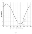
- Fig. 6 is a graph showing the first angular velocity versus the rotation angle after correction.
- the horizontal axis is the rotation angle of the first detection axis 11D before correction
- the vertical axis is the first angular velocity.
- the horizontal axis is the rotation angle of the first detection axis 11D after correction
- the vertical axis is the first angular velocity.
- the rotation mechanism 13 is driven to rotate the first detection axis 11D of the first angular velocity sensor 11 from the reference direction RD.
- the first angular velocity sensor 11 is operated to detect the first angular velocity at a rotation angle ⁇ at a predetermined interval.
- the measurement unit 10 rotates by an angle ⁇ in the same direction as the rotation direction of the rotation mechanism 13.
- the initial reference direction before the original rotation is RD0
- the reference direction RD of the rotation mechanism 13 rotates by an angle ⁇ from the initial reference direction RD0. Therefore, the true rotation angle from the initial reference direction RD0 on the first detection axis 11D of the first angular velocity sensor 11 is ⁇ + ⁇ . Therefore, when the rotary encoder 13A measures the rotation angle as ⁇ , the first angular velocity sensor 11 detects the first angular velocity at the true rotation angle ⁇ + ⁇ . Therefore, as shown in FIG. 5, the first angular velocity changes discontinuously at the time Tm when the measurement unit 10 rotates. When the first angular velocity changes discontinuously in this way, an error occurs when fitting the plot of the first angular velocity with a sine function.
- the correction unit 24 calculates the angle ⁇ based on the second angular velocity. As shown in FIG. 6, the correction unit 24 adds the rotation angle ⁇ to the rotation angle ⁇ measured by the rotary encoder 13A after the timing Tm. Although the plot of the first angular velocity is interrupted once at the timing Tm, the deviation of the plot from the sine function can be suppressed. In other words, the error that occurs when fitting with a sine function can be suppressed. Therefore, compared to measuring the azimuth based on the graph shown in FIG. 5, the measurement accuracy of the azimuth can be improved by measuring the azimuth based on the graph shown in FIG. 6.
- the azimuth measuring device 1 includes a first angular velocity sensor 11 having a first detection axis 11D extending in the horizontal direction, a rotation mechanism 13 that rotates the first detection axis 11D around a rotation axis 13R extending in the vertical direction, and a second angular velocity sensor 12 used to correct the rotation angle ⁇ of the first detection axis 11D in the rotation mechanism 13, the second angular velocity sensor having a second detection axis 12D extending along the vertical direction and detecting a second angular velocity around the second detection axis 12D as its rotation center.
- the error in the rotation angle ⁇ caused by the rotation of the measurement unit 10 can be corrected based on the second angular velocity, thereby suppressing the occurrence of azimuth measurement errors.
- Fig. 7 is a schematic diagram showing the configuration of an orientation measuring device according to the second embodiment.
- the orientation measuring device 2 further includes an attitude control unit 230.
- the measurement unit 210 of the orientation measuring device 2 further includes an attitude measurement mechanism 214.
- the control unit 220 of the orientation measuring device 2 further includes an attitude information acquisition unit 225 and an attitude control unit 226.
- the attitude control unit 230 corrects the rotation around a rotation axis extending along the horizontal direction (XY plane) in the measurement unit 210, and controls the attitude of the first angular velocity sensor 11, the second angular velocity sensor 12, and the rotation mechanism 13.
- the attitude control unit 230 includes a two-axis gimbal mechanism 231 and a servo motor 232 that operates the two-axis gimbal mechanism 231.
- the attitude measurement mechanism 214 measures the rotation around a rotation axis extending along the XY plane of the measurement unit 210. In other words, the attitude measurement mechanism 214 measures the attitude of the first angular velocity sensor 11, the second angular velocity sensor 12, and the rotation mechanism 13.
- the attitude measurement mechanism 214 is, for example, an inertial measurement unit (IMU).
- the attitude information acquisition unit 225 acquires information about the attitude of the measurement unit 210 from the attitude measurement mechanism 214.
- the attitude control unit 226 servo-controls the two-axis gimbal mechanism 231 via the servo motor 232 based on the information about the attitude of the measurement unit 210 acquired by the attitude information acquisition unit 225.
- the orientation measurement device 2 is equipped with an attitude control unit 230, which makes it possible to suppress the occurrence of orientation measurement errors caused by rotation around a rotation axis extending along the horizontal direction in the measurement unit 210, thereby improving the orientation measurement accuracy.
- the attitude control unit 230 performs attitude control based on the measurement results of the attitude measurement mechanism 214, so that the horizontal attitude of the measurement unit 210 can be maintained with high accuracy.
- the attitude control unit 230 controls the attitude of the measurement unit 210 by servo control based on the measurement results of the attitude measurement mechanism 214, but this is not limited to this.
- the azimuth measurement device may control the attitude of the measurement unit by constantly operating the two-axis gimbal mechanism with a constant output, without measuring the attitude of the attitude control unit.
- the attitude control mechanism is not limited to a two-axis gimbal mechanism.
- the attitude control mechanism may be two or more pillars with lifting functions connected to the bottom surface of the measurement unit.
- the attitude control mechanism may be a passive type attitude control mechanism having an air spring, a spring, an oil damper, an air damper, urethane rubber, or the like.
- a first angular velocity sensor having a first detection axis extending along a horizontal direction and configured to detect a first angular velocity about a rotation center of the first detection axis; a rotation mechanism having a rotation axis extending along a vertical direction and configured to rotate a first detection axis of the first angular velocity sensor around the rotation axis; a second angular velocity sensor used to correct a rotation angle of a first detection axis in the rotation mechanism, the second angular velocity sensor having a second detection axis extending along a vertical direction and detecting a second angular velocity about a rotation center of the second detection axis; Orientation measuring device.
- ⁇ 2> a correction unit that corrects a rotation angle of the first detection axis in the rotation mechanism based on the second angular velocity; 2.
- a direction measuring device according to claim 1.
- a calculation unit is further provided that calculates an orientation by plotting the first angular velocity against a rotation angle and fitting the plot with a sine function.
- the correction unit corrects the rotation angle after being acquired from the rotation mechanism.
- the azimuth measuring device according to ⁇ 2> or ⁇ 3>.
- the correction unit adds a rotation angle calculated based on the second angular velocity measured by the second angular velocity sensor to a rotation angle of the first detection axis acquired from the rotation mechanism;
- the orientation measuring device according to ⁇ 4>.
- the correction unit corrects the rotation angle before it is acquired from the rotation mechanism.
- the azimuth measuring device according to ⁇ 2> or ⁇ 3>.
- the correction unit determines a value obtained by subtracting the second angular velocity measured by the second angular velocity sensor from a set value in a normal state as the rotational angular velocity of the rotation mechanism.
- the present invention further includes an attitude control unit for controlling the attitudes of the first angular velocity sensor, the rotation mechanism, and the second angular velocity sensor.
- the azimuth measuring device according to any one of ⁇ 1> to ⁇ 7>.
- the attitude control unit is a two-axis gimbal mechanism.
- the rotation mechanism further includes an attitude measurement mechanism for measuring the attitudes of the first angular velocity sensor, the rotation mechanism, and the second angular velocity sensor.
- the attitude control unit performs attitude control based on the measurement results of the attitude measurement mechanism.
- the azimuth measuring device according to ⁇ 8> or ⁇ 9>.
- one aspect of the present invention provides a direction measurement device that can improve direction measurement accuracy.
Landscapes
- Engineering & Computer Science (AREA)
- Radar, Positioning & Navigation (AREA)
- Remote Sensing (AREA)
- Physics & Mathematics (AREA)
- General Physics & Mathematics (AREA)
- Manufacturing & Machinery (AREA)
- Life Sciences & Earth Sciences (AREA)
- Environmental & Geological Engineering (AREA)
- General Life Sciences & Earth Sciences (AREA)
- Geology (AREA)
- Electromagnetism (AREA)
- Gyroscopes (AREA)
Priority Applications (3)
| Application Number | Priority Date | Filing Date | Title |
|---|---|---|---|
| EP24859158.8A EP4715329A1 (en) | 2023-08-29 | 2024-07-03 | Azimuth measurement device |
| JP2025542757A JPWO2025047113A1 (https=) | 2023-08-29 | 2024-07-03 | |
| CN202480050484.2A CN121620680A (zh) | 2023-08-29 | 2024-07-03 | 方位测量装置 |
Applications Claiming Priority (2)
| Application Number | Priority Date | Filing Date | Title |
|---|---|---|---|
| JP2023-138507 | 2023-08-29 | ||
| JP2023138507 | 2023-08-29 |
Related Child Applications (1)
| Application Number | Title | Priority Date | Filing Date |
|---|---|---|---|
| US19/440,984 Continuation US20260126289A1 (en) | 2023-08-29 | 2026-01-06 | Azimuth measurement device |
Publications (1)
| Publication Number | Publication Date |
|---|---|
| WO2025047113A1 true WO2025047113A1 (ja) | 2025-03-06 |
Family
ID=94818681
Family Applications (1)
| Application Number | Title | Priority Date | Filing Date |
|---|---|---|---|
| PCT/JP2024/024079 Pending WO2025047113A1 (ja) | 2023-08-29 | 2024-07-03 | 方位計測装置 |
Country Status (4)
| Country | Link |
|---|---|
| EP (1) | EP4715329A1 (https=) |
| JP (1) | JPWO2025047113A1 (https=) |
| CN (1) | CN121620680A (https=) |
| WO (1) | WO2025047113A1 (https=) |
Citations (5)
| Publication number | Priority date | Publication date | Assignee | Title |
|---|---|---|---|---|
| JPH0526672A (ja) * | 1991-07-26 | 1993-02-02 | Tokimec Inc | 方位検出装置 |
| JP2001349733A (ja) * | 2000-06-06 | 2001-12-21 | Hitachi Cable Ltd | 方位センサ |
| JP2002296037A (ja) * | 2001-03-30 | 2002-10-09 | Tokimec Inc | ジャイロコンパス装置 |
| JP2004309227A (ja) * | 2003-04-03 | 2004-11-04 | Asahi Kasei Electronics Co Ltd | 計測装置、方位角計測装置及びキャリブレーションプログラム、並びにキャリブレーション方法 |
| JP2010281598A (ja) * | 2009-06-02 | 2010-12-16 | Fujitsu Ltd | センサ較正装置 |
-
2024
- 2024-07-03 EP EP24859158.8A patent/EP4715329A1/en active Pending
- 2024-07-03 WO PCT/JP2024/024079 patent/WO2025047113A1/ja active Pending
- 2024-07-03 JP JP2025542757A patent/JPWO2025047113A1/ja active Pending
- 2024-07-03 CN CN202480050484.2A patent/CN121620680A/zh active Pending
Patent Citations (5)
| Publication number | Priority date | Publication date | Assignee | Title |
|---|---|---|---|---|
| JPH0526672A (ja) * | 1991-07-26 | 1993-02-02 | Tokimec Inc | 方位検出装置 |
| JP2001349733A (ja) * | 2000-06-06 | 2001-12-21 | Hitachi Cable Ltd | 方位センサ |
| JP2002296037A (ja) * | 2001-03-30 | 2002-10-09 | Tokimec Inc | ジャイロコンパス装置 |
| JP2004309227A (ja) * | 2003-04-03 | 2004-11-04 | Asahi Kasei Electronics Co Ltd | 計測装置、方位角計測装置及びキャリブレーションプログラム、並びにキャリブレーション方法 |
| JP2010281598A (ja) * | 2009-06-02 | 2010-12-16 | Fujitsu Ltd | センサ較正装置 |
Non-Patent Citations (1)
| Title |
|---|
| I.P. PRIKHODKOS.A. ZOTOVALEXANDER A. TRUSOVA.M. SHKEL: "What is MEMS Gyrocompassing? Comparative Analysis of May tagging and Carouseling", JOURNAL OF MICROELECTROMECHANICAL SYSTEMS, vol. 22, no. 6, December 2013 (2013-12-01), pages 1257 - 1266 |
Also Published As
| Publication number | Publication date |
|---|---|
| CN121620680A (zh) | 2026-03-06 |
| JPWO2025047113A1 (https=) | 2025-03-06 |
| EP4715329A1 (en) | 2026-03-25 |
Similar Documents
| Publication | Publication Date | Title |
|---|---|---|
| CN103292809B (zh) | 一种单轴旋转式惯导系统及其专用误差自补偿方法 | |
| CN103743413B (zh) | 倾斜状态下调制寻北仪安装误差在线估计与寻北误差补偿方法 | |
| CN109211269A (zh) | 一种双轴旋转惯导系统姿态角误差标定方法 | |
| CN111561948B (zh) | 四轴冗余捷联惯导的系统级标定方法 | |
| CN104697521B (zh) | 一种采用陀螺冗余斜交配置方式测量高速旋转体姿态和角速度的方法 | |
| CN103727939B (zh) | 一种双轴旋转的姿态测量系统及其测量方法 | |
| CN110621961A (zh) | 低成本惯性导航系统 | |
| CN116242397A (zh) | 一种速度误差修正模型下的双惯导协同标定方法 | |
| CN103940445B (zh) | 一种单轴旋转惯导系统惯性器件误差补偿方法 | |
| CN112179340B (zh) | 一种冗余配置惯性测量单元双轴旋转调制方法 | |
| CN103335643A (zh) | 一种模块化光纤陀螺罗经 | |
| CN114111753A (zh) | 一种光纤陀螺寻北仪 | |
| CN110779548B (zh) | 一种惯性测量单元偏轴-旋转复合调制误差补偿方法 | |
| CN110986934B (zh) | 一体化双轴旋转惯导天文组合导航系统的导航方法及系统 | |
| JP2001141507A (ja) | 慣性航法装置 | |
| CN112304339B (zh) | 一种卫星移动通信天线的惯导校准方法 | |
| WO2025047113A1 (ja) | 方位計測装置 | |
| US20260126289A1 (en) | Azimuth measurement device | |
| CN216483089U (zh) | 一种光纤陀螺寻北仪 | |
| CN111397635A (zh) | 一种mems惯性导航系统旋转调制方法 | |
| CN115265591B (zh) | 一种双轴旋转惯导imu与转位机构安装误差的标定方法 | |
| US20060053887A1 (en) | Generalized inertial measurement error reduction through multiple axis rotation during flight | |
| CN105203133B (zh) | 一种带旋转机构的惯性导航系统用测角装置快速寻零方法 | |
| CN216977925U (zh) | 光纤陀螺仪分辨率的测量系统、可读存储介质 | |
| CN117782154A (zh) | 一种地面旋转状态下的滚转角测量精度评估方法 |
Legal Events
| Date | Code | Title | Description |
|---|---|---|---|
| 121 | Ep: the epo has been informed by wipo that ep was designated in this application |
Ref document number: 24859158 Country of ref document: EP Kind code of ref document: A1 |
|
| ENP | Entry into the national phase |
Ref document number: 2025542757 Country of ref document: JP Kind code of ref document: A |
|
| WWE | Wipo information: entry into national phase |
Ref document number: 2025542757 Country of ref document: JP |
|
| WWE | Wipo information: entry into national phase |
Ref document number: 2024859158 Country of ref document: EP |
|
| ENP | Entry into the national phase |
Ref document number: 2024859158 Country of ref document: EP Effective date: 20251219 |
|
| ENP | Entry into the national phase |
Ref document number: 2024859158 Country of ref document: EP Effective date: 20251219 |
|
| ENP | Entry into the national phase |
Ref document number: 2024859158 Country of ref document: EP Effective date: 20251219 |
|
| ENP | Entry into the national phase |
Ref document number: 2024859158 Country of ref document: EP Effective date: 20251219 |
|
| ENP | Entry into the national phase |
Ref document number: 2024859158 Country of ref document: EP Effective date: 20251219 |
|
| WWP | Wipo information: published in national office |
Ref document number: 2024859158 Country of ref document: EP |