WO2025047097A1 - 無線端末、無線アクセスネットワークノード、及びこれらの方法 - Google Patents
無線端末、無線アクセスネットワークノード、及びこれらの方法 Download PDFInfo
- Publication number
- WO2025047097A1 WO2025047097A1 PCT/JP2024/023713 JP2024023713W WO2025047097A1 WO 2025047097 A1 WO2025047097 A1 WO 2025047097A1 JP 2024023713 W JP2024023713 W JP 2024023713W WO 2025047097 A1 WO2025047097 A1 WO 2025047097A1
- Authority
- WO
- WIPO (PCT)
- Prior art keywords
- low power
- wireless terminal
- wake
- measurement
- primary transceiver
- Prior art date
- Legal status (The legal status is an assumption and is not a legal conclusion. Google has not performed a legal analysis and makes no representation as to the accuracy of the status listed.)
- Pending
Links
Images





Classifications
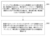
-
- H—ELECTRICITY
- H04—ELECTRIC COMMUNICATION TECHNIQUE
- H04W—WIRELESS COMMUNICATION NETWORKS
- H04W16/00—Network planning, e.g. coverage or traffic planning tools; Network deployment, e.g. resource partitioning or cells structures
- H04W16/18—Network planning tools
-
- H—ELECTRICITY
- H04—ELECTRIC COMMUNICATION TECHNIQUE
- H04W—WIRELESS COMMUNICATION NETWORKS
- H04W24/00—Supervisory, monitoring or testing arrangements
- H04W24/10—Scheduling measurement reports ; Arrangements for measurement reports
-
- H—ELECTRICITY
- H04—ELECTRIC COMMUNICATION TECHNIQUE
- H04W—WIRELESS COMMUNICATION NETWORKS
- H04W52/00—Power management, e.g. Transmission Power Control [TPC] or power classes
- H04W52/02—Power saving arrangements
-
- H—ELECTRICITY
- H04—ELECTRIC COMMUNICATION TECHNIQUE
- H04W—WIRELESS COMMUNICATION NETWORKS
- H04W76/00—Connection management
- H04W76/20—Manipulation of established connections
- H04W76/28—Discontinuous transmission [DTX]; Discontinuous reception [DRX]
-
- H—ELECTRICITY
- H04—ELECTRIC COMMUNICATION TECHNIQUE
- H04W—WIRELESS COMMUNICATION NETWORKS
- H04W88/00—Devices specially adapted for wireless communication networks, e.g. terminals, base stations or access point devices
- H04W88/02—Terminal devices
-
- Y—GENERAL TAGGING OF NEW TECHNOLOGICAL DEVELOPMENTS; GENERAL TAGGING OF CROSS-SECTIONAL TECHNOLOGIES SPANNING OVER SEVERAL SECTIONS OF THE IPC; TECHNICAL SUBJECTS COVERED BY FORMER USPC CROSS-REFERENCE ART COLLECTIONS [XRACs] AND DIGESTS
- Y02—TECHNOLOGIES OR APPLICATIONS FOR MITIGATION OR ADAPTATION AGAINST CLIMATE CHANGE
- Y02D—CLIMATE CHANGE MITIGATION TECHNOLOGIES IN INFORMATION AND COMMUNICATION TECHNOLOGIES [ICT], I.E. INFORMATION AND COMMUNICATION TECHNOLOGIES AIMING AT THE REDUCTION OF THEIR OWN ENERGY USE
- Y02D30/00—Reducing energy consumption in communication networks
- Y02D30/70—Reducing energy consumption in communication networks in wireless communication networks
Definitions
- This disclosure relates to wireless communication systems.
- the 3rd Generation Partnership Project (3GPP®) is investigating ultra-low power mechanisms or solutions for Release 18 and beyond that can improve the energy efficiency of User Equipments (UEs) and support low latency (see, for example, Non-Patent Document 1-15).
- the mechanisms aim to achieve substantial gains compared to the UE power saving mechanisms introduced in 3GPP Releases 15, 16, and 17.
- Non-Patent Document 1 currently, when a UE is in Radio Resource Control (RRC)_IDLE or RRC_INACTIVE state, the UE needs to wake up periodically once per Discontinuous Reception (DRX) cycle (i.e., paging cycle). Specifically, the UE needs to monitor Paging Occasion (PO) or Paging Early Indication (PEI) opportunities periodically once per DRX or paging cycle. This action governs the power consumption of a UE in RRC_IDLE or RRC_INACTIVE state during periods when there is no signal or data traffic. If the UE could wake up only when triggered, such as when paging, the power consumption could be dramatically reduced. To achieve this, the low power mechanism under consideration uses a wake-up signal that triggers the Main Radio (MR) and a receiver with the ability to monitor the wake-up signal with ultra-low power consumption.
- MR Main Radio
- the wake-up signal under consideration is called, for example, the Low Power (LP) Wake-Up Signal (WUS) (LP-WUS).
- a low power receiver capable of monitoring the LP-WUS and separate from the MR is called, for example, the Low Power (LP) Wake-Up Receiver (LP-WUR), or LR for short for LP-WUR.
- the MR is a transceiver (transmitting and receiving module) for receiving NR signals and channels, operates for data transmission and reception, and can be turned off or set to deep sleep unless powered on.
- the deep sleep state achieved by the use of LP-WUS and LP-WUR is called, for example, the ultra-deep sleep state.
- the deep sleep state supported by current UEs is achieved by the PEI mechanism introduced in 3GPP Release 17.
- Non-Patent Document 2 describes considerations related to LP-WUS and LP-WUR, including LP-WUR receiver architecture, LP-WUS signal design, and LP-WUS related Layer-1 (L1) procedures.
- LP-WUS related L1 procedures include Radio Resource Management (RRM) measurements in RRC_IDLE and INACTIVE states and RRC_CONNECTED states, LP-WUR synchronization, LP-WUS monitoring, LP-WUS activation and deactivation procedures, and LP-WUS coverage related procedures.
- RRM Radio Resource Management
- LP-WUS content candidates for RRC_IDLE and INACTIVE include information about which users the LP-WUS is targeting (e.g., UE-group, UE-subgroup, or UE-ID).
- LP-WUS content candidates include cell information, tracking area information, Radio Access Network (RAN) area information, System Information (SI) change indication, Earthquake and Tsunami Warning System (ETWS) Commercial Mobile Alert System (CMAS) information.
- RAN Radio Access Network
- SI System Information
- ETWS Earthquake and Tsunami Warning System
- CMAS Commercial Mobile Alert System
- 3GPP will consider the feasibility of RRM measurements being made by the LP-WUR for at least the serving or camping cell based on signals detected by the LP-WUR.
- LP-WUR synchronization there are several options for the synchronization signal used by the LP-WUR, including aperiodic signals transmitted as part of the LP-WUS, periodic signals transmitted separately from the LP-WUS, and combinations of these.
- the synchronization or reference signal for LP-WUR synchronization and for L1 measurements is called the LP Synchronization Signal (LP-SS) or LP Reference Signal (LP-RS).
- LP-SS LP Synchronization Signal
- LP-RS LP Reference Signal
- 3GPP will consider a fallback mechanism whereby the MR will switch to legacy operation if the LP-WUS channel conditions are not sufficient (e.g., below a threshold).
- Non-patent document 3-13 is a contribution submitted to a recent meeting of the 3GPP Technical Specification Group (TSG) Radio Access Network (RAN) Working Group #2 (WG2) (RAN2).
- TSG Technical Specification Group
- RAN Radio Access Network
- WG2 Working Group #2
- Non-patent document 3 states that since the waveforms handled by the LP-WUR are different from those handled by the MR, a different reference signal that can be received by the LP-WUR, i.e., the LP-RS, needs to be used for RRM measurements by the LP-WUR.
- Non-patent document 3 suggests that the UE should consider what type of RRM measurements to perform using the LP-WUR, e.g., serving cell, intra-frequency, and inter-frequency.
- 3GPP TS 2013-01-032452 (2013) suggests considering the option for the UE to use RRM measurements from the LP-WUR together with legacy measurements in the cell reselection procedure. Specifically, even if the UE can perform RRM measurements using the LP-WUR, not all measurements are performed by the LP-WUR. For example, if neighbor cells do not transmit LP-RS (or LP-SS), measurements on those cells need to be performed in the MR (i.e., legacy measurements). During cell reselection, the UE needs to compare the signal strength of receivable neighbor cells with the signal strength of the serving cell, so it is necessary to consider how the UE can perform cell ranking using two different types of RRM measurements.
- LP-RS or LP-SS
- mapping that converts the RRM measurements from the LP-WUR to the scale of the legacy RRM measurements.
- Such a mapping could be either a predefined offset in the specification or a semi-static parameter that can be periodically calibrated based on the measurements. If such a mapping is possible, it would enable compatible and reliable comparison of measurements from the LP-WUR and the MR.
- Non-patent document 4 states that different mechanisms need to be considered depending on whether the LP-WUS has full or partial coverage.
- Full coverage means that the coverage of the LP-WUS is the same or comparable to the coverage of the existing reference signal (i.e., Secondary Synchronization Signal (SSS) or Synchronization Signal (SS)/Physical Broadcast Channel (PBCH) block (SSB)).
- Partial coverage means that the coverage of the LP-WUS is narrower than the coverage of the existing reference signal. Partial coverage may also be referred to as different coverage or coverage mismatch. In the case of full LP-WUS coverage, there is a possibility that the LP-WUS may be continuously available as the UE moves between cells.
- Non-patent document 10 proposes two methods for activating and deactivating LP-WUS in LP-WUS-capable UE.
- the gNB can instruct the LP-WUS-capable UE to enter ultra-deep sleep mode or power state and activate monitoring of common, grouped, or dedicated LP-WUS via an RRC Release message.
- the UE's MR immediately enters ultra-deep sleep mode and the UE's LR starts monitoring the corresponding LP-WUS.
- the gNB can wake up the UE's MR by sending the corresponding LP-WUS.
- the gNB can activate the common or grouped LP-WUS configuration via a System Information Block (SIB).
- SIB System Information Block
- the MR of the LP-WUS-capable UE enters ultra-deep sleep mode while the UE is in RRC_IDLE or RRC_INACTIVE state.
- the gNB transmits LP-WUS to wake up LP-WUS-capable UEs.
- Non-patent document 11 includes the following disclosure regarding mobility in full LP-WUS coverage:
- the UE may remain in LP-WUS coverage.
- the UE should rely on LR while stopping or skipping MR procedures as much as possible.
- the UE would stay in LR mode and turn off MR as long as the LP-WUS signal strength is above the LR mobility threshold. This assumes that the UE is able to evaluate the LP-WUS signal strength of the serving and neighboring cells and can operate in LR mode even when changing cells.
- RAN1 currently focuses on offloading RRM measurements of serving or camping cells to the LR and leaving RRM measurements of neighboring cells to the MR.
- AS Access Stratum
- the LP-WUS can provide information to ensure that the UE can operate in LR mode after a cell change, the UE does not need to resume legacy procedures in the MR.
- the LP-WUS can be used for RRM of the serving cell but not for RRM of neighboring cells
- the UE will start RRM measurements with the MR, while the LR will continue to receive the LP-WUS for paging, etc.
- the MR will perform cell reselection based on the RRM measurements.
- Non-patent document 12 describes RRM measurements for IDLE/INACTIVE mobility in LP-WUS full and partial coverage.
- the UE can perform serving cell measurements based on LP-WUS signals (e.g., LP-SS or LP-RS).
- LP-WUS signals e.g., LP-SS or LP-RS.
- the UE can determine that the LP-WUS signal alone in ultra-deep sleep state does not work well, but cannot determine that the quality of the serving cell is poor.
- the UE needs to leave the ultra-deep sleep state and perform legacy RRM measurements based on the SSB of the serving cell using MR. And in normal state, if the quality of the serving cell based on SSB measurements falls below a threshold, the UE starts SSB measurements of neighboring cells. In contrast, in the case of LP-WUS full coverage, if the LP-WUS signal quality falls below the threshold, the UE determines that the quality of the current serving cell is poor, leaves the ultra-deep sleep state, and performs legacy RRM measurements based on the SSB of the serving cell and neighboring cells using MR.
- Non-Patent Document 13 includes the following disclosure regarding mobility and RRM measurements using LP-WUR.
- LP-SS LP-WUR-specific reference signal
- Non-Patent Document 13 proposes considering the adoption of Solution 1, i.e., RRM measurements by LP-WUR using SSB.
- Non-Patent Document 15 describes a unified solution for cell reselection considering both LP-WUS full coverage and partial coverage scenarios.
- Non-Patent Document 15 is an update of Non-Patent Document 11 and includes the following disclosure:
- the problem is when to start the RRM measurement by the MR. Because if the UE starts measuring neighboring cells by the MR after leaving the LP-WUS coverage, it will be too late when the UE's moving speed is high and the NR cell coverage is not much larger than the LP-WUS coverage, which will degrade the mobility performance.
- a separate threshold of LP-WUS signal strength for cell reselection (e.g., thresholdMob) can be introduced, which can be smaller than the threshold for fallback purposes.
- thresholdMob a separate threshold of LP-WUS signal strength for cell reselection
- the LP-WUS has the same coverage as an NR cell, the question arises as to whether the UE needs to wake up the MR for cell reselection even when it is within the coverage of the LP-WUS.
- the ideal procedure is that the UE stays in LR mode and turns off the MR as long as the signal strength of the LP-WUS is above a threshold. This assumes that the UE can evaluate the signal strength of the LP-WUS in the serving cell and neighboring cells and can work in LR mode even when the cell is changed.
- the following two AS criteria can be supported for LR mobility.
- the UE can stay in LR mode as long as the signal strength of the LP-WUS is above a threshold (e.g., thresholdMob), and there is no need to resume legacy procedures in the MR.
- a threshold e.g., thresholdMob
- the LP-WUS can provide information to ensure that the UE can work in LR mode after a cell change, the UE can use the LR for cell reselection.
- the UE will start RRM measurements with the MR, while the LR will continue to receive the LP-WUS for paging, etc.
- the MR will perform cell reselection based on the RRM measurements.
- Non-Patent Documents 1-14 do not teach how MDT, SDT, and network slicing related procedures and operations need to be adapted or modified when a UE uses LP-WUS and LP-WUR.
- One of the objectives that the embodiments disclosed in this specification aim to achieve is to provide an apparatus, method, and program that contribute to solving at least one of the multiple issues related to realizing a low power consumption mechanism using LP-WUS and LP-WUR, including the issues described above. It should be noted that this objective is only one of the multiple objectives that the multiple embodiments disclosed in this specification aim to achieve. Other objectives or issues and novel features will become apparent from the description of this specification or the accompanying drawings.
- a wireless terminal in a first aspect, includes a primary transceiver and a low power wake-up receiver. The wireless terminal is further configured to record MDT measurement results including measurement results of low power wake-up related signals using the low power wake-up receiver while at least the primary transceiver is in an ultra deep sleep power state.
- a method performed by a wireless terminal includes recording MDT measurements including measurements of low power wake-up related signals using a low power wake-up receiver while at least a primary transceiver is in an ultra-deep sleep power state.
- a radio access network (RAN) node is configured to send an MDT measurement configuration to a wireless terminal, the MDT measurement configuration including a configuration or indication of measurement logging of low power wake-up related signals.
- a method performed by a RAN node includes transmitting an MDT measurement configuration to a radio terminal, the MDT measurement configuration including a configuration or indication of measurement logging of low power wake-up related signals.
- a wireless terminal in a fifth aspect, includes a primary transceiver and a low power wake-up receiver.
- the wireless terminal is further configured to store measurement results for IDLE/INACTIVE measurement reporting, including measurement results of low power wake-up related signals using the low power wake-up receiver while at least the primary transceiver is in an ultra deep sleep power state.
- a method performed by a wireless terminal includes storing measurement results for IDLE/INACTIVE measurement reporting, including measurement results of low power wake-up related signals using a low power wake-up receiver while at least a primary transceiver is in an ultra-deep sleep power state.
- the RAN node is configured to transmit information to the wireless terminal indicating that the IDLE/INACTIVE measurements include measurements of low power wake-up related signals.
- a method performed by a RAN node includes transmitting information to a wireless terminal indicating that the IDLE/INACTIVE measurements include measurements of low power wake-up related signals.
- a wireless terminal in a ninth aspect, includes a primary transceiver and a low power wake-up receiver. The wireless terminal is further configured to perform an SDT procedure using the primary transceiver that has woken up from an ultra-deep sleep power state by skipping a comparison between a first measurement value obtained from an SSB measurement and a first threshold value.
- a method performed by a wireless terminal having a primary transceiver and a low power wake-up receiver includes performing an SDT procedure with the primary transceiver woken up from an ultra-deep sleep power state by skipping a comparison between a first measurement value obtained from an SSB measurement and a first threshold value.
- the RAN node is configured to transmit configuration information to the radio terminal indicating that a comparison between a first measurement value obtained from the SSB measurement and a first threshold value is skipped in determining whether the conditions for initiating an SDT procedure are met.
- the method performed by the RAN node includes transmitting configuration information to the wireless terminal indicating that a comparison between a first measurement value obtained from the SSB measurement and a first threshold value is skipped in determining whether a condition for initiating an SDT procedure is met.
- a wireless terminal in a thirteenth aspect, includes a primary transceiver and a low power wake-up receiver. The wireless terminal is further configured to attempt to measure or detect a low power wake-up related signal of a neighboring cell supporting the intended network slice if a quality of a low power wake-up related signal of a serving cell or serving cell frequency measured using the low power wake-up receiver degrades while the primary transceiver is in an ultra deep sleep power state.
- a method performed by a wireless terminal having a primary transceiver and a low power wake-up receiver includes attempting to measure or detect low power wake-up related signals of a neighboring cell supporting an intended network slice if a quality of a low power wake-up related signal of a serving cell or serving cell frequency measured using the low power wake-up receiver degrades while the primary transceiver is in an ultra deep sleep power state.
- a wireless terminal in a fifteenth aspect, includes a primary transceiver and a low power wake-up receiver.
- the wireless terminal is further configured to, if there is a frequency with a higher priority for cell reselection than a serving cell frequency, attempt to measure or detect a low power wake-up related signal of a neighboring cell supporting the intended network slice using the low power wake-up receiver on the higher priority frequency while the primary transceiver is in the ultra deep sleep power state.
- a method performed by a wireless terminal having a primary transceiver and a low power wake-up receiver includes, if a frequency has a higher priority for cell reselection than a serving cell frequency, attempting to measure or detect a low power wake-up related signal of a neighboring cell supporting an intended network slice using the low power wake-up receiver on the higher priority frequency while the primary transceiver is in an ultra deep sleep power state.
- the program includes a set of instructions (software code) that, when loaded into a computer, causes the computer to perform a method according to any of the above aspects.
- the above-mentioned aspects provide an apparatus, method, and program that contribute to solving at least one of the problems related to realizing a low power consumption mechanism using LP-WUS and LP-WUR.
- FIG. 1 illustrates an example configuration of a wireless communication system related to one or more embodiments.
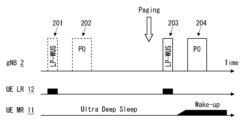
- FIG. 13 illustrates an example of paging when a UE is in an ultra-deep sleep power state, in accordance with one or more embodiments.
- FIG. 1 illustrates an example of cell reselection using LP-WUR, in accordance with one or more embodiments.
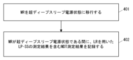
- 1 is a flowchart illustrating an example of a UE operation in accordance with one or more embodiments.
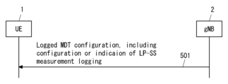
- FIG. 1 is a sequence diagram illustrating an example of UE and gNB operation in accordance with one or more embodiments.
- FIG. 13 illustrates an example of a format for a LoggedMeasurementConfiguration message, in accordance with one or more embodiments.
- FIG. 1 is a flowchart illustrating an example of a UE operation in accordance with one or more embodiments.
- FIG. 1 is a sequence diagram illustrating an example of UE and gNB operation in accordance with one or more embodiments.
- FIG. 11 illustrates an example of a format for a MeasIdleConfig information element, in accordance with one or more embodiments.
- 1 is a flowchart illustrating an example of a UE operation in accordance with one or more embodiments.
- FIG. 1 is a flowchart illustrating an example of a UE operation in accordance with one or more embodiments.
- FIG. 1 is a sequence diagram illustrating an example of UE and gNB operation in accordance with one or more embodiments.
- FIG. 1 is a sequence diagram illustrating an example of UE and gNB operation in accordance with one or more embodiments.
- FIG. 1 is a sequence diagram illustrating an example of UE and gNB operation in accordance with one or more embodiments.
- a diagram illustrating an example of a format of a SIB1 message in accordance with one or more embodiments.
- a diagram illustrating an example of a format of a RRCRelease message in accordance with one or more embodiments.
- FIG. 1 is a flowchart illustrating an example of a UE operation in accordance with one or more embodiments.
- 1 is a flowchart illustrating an example of a UE operation in accordance with one or more embodiments.
- FIG. 2 is a block diagram illustrating an example configuration of a UE in accordance with one or more embodiments.
- multiple embodiments described below may be used alone, or two or more embodiments may be combined as appropriate. These multiple embodiments may have novel features that are different from each other. Thus, these multiple embodiments may contribute to achieving different objectives or solving different problems, and may contribute to providing different effects.
- if may be construed to mean “when,” “while,” “at or around the time,” “after,” “upon,” “in response to determining,” “in accordance with a determination,” or “in response to detecting.” These expressions may be construed to have the same meaning, depending on the context.
- FIG. 1 shows an example configuration of a wireless communication system related to multiple embodiments.
- Each of the elements shown in FIG. 1 is a network function, and provides an interface defined by, for example, 3GPP.
- Each element (network function) shown in FIG. 1 can be implemented, for example, as a network element on dedicated hardware, as a software instance running on dedicated hardware, or as a virtualized function instantiated on an application platform.
- the wireless communication system shown in FIG. 1 includes a UE 1 and a gNB 2.
- the UE 1 may be referred to as a wireless terminal, a mobile terminal, a mobile station, or other terms such as a wireless transmit receive unit (WTRU).
- the gNB 2 may be referred to as a Radio Access Network (RAN) node, a base station, a radio station, or an access point.
- the gNB 2 may be a combination of a gNB-Central Unit (gNB-CU) and one or more gNB-Distributed Units (gNB-DUs) in a cloud RAN (C-RAN) deployment.
- the C-RAN is also referred to as a CU/DU split.
- the gNB-CU may include a Control Plane (CP) Unit (i.e., gNB-CU-CP) and one or more User Plane (UP) Units (i.e., gNB-CU-UPs).
- CP Control Plane
- UE 1 and gNB 2 support a low power mechanism using a low power wake-up signal (LP-WUS) and a low power wake-up receiver (LP-WUR).
- UE 1 has a main radio (MR) 11 and a LP-WUR (LR) 12.
- MR 11 may be referred to as the main transceiver, or simply as the transceiver (relative to the LR).
- MR 11 is a transceiver (i.e., transmit and receive module) for receiving NR signals and channels.
- NR signals and channels include, for example, Sounding Reference Signal (SRS), Physical Random Access Channel (PRACH) Preamble, Physical Uplink Control Channel (PUCCH), Physical Uplink Shared Channel (PUSCH), Reference Signal (RS), Synchronization Signal (SS), Physical Broadcast Channel (PBCH), Physical Downlink Control Channel (PDCCH), and Physical Downlink Shared Channel (PDSCH).
- the MR 11 may operate for signal transmission and reception including SRS transmission, PRACH Preamble transmission, PUCCH transmission, PUSCH transmission, RS reception, SS reception, PBCH reception (or SSB reception combining SS and PBCH), PDCCH reception, and PDSCH reception.
- MR 11 can be set to be off or in a deep sleep power state or mode unless it is powered on.
- the deep sleep state of MR 11 achieved by use of LP-WUS and LR 12 may be referred to as an ultra deep sleep state, ultra deep sleep power state, or ultra deep sleep mode to distinguish it from the deep sleep state in DRX in RRC_IDLE and INACTIVE states of 3GPP Release 17 (achieved by the PEI mechanism).
- the deep sleep state of MR 11 may be referred to as an ultra low power state, ultra power saving state, or ultra power saving mode.
- it may be referred to as an improved (or enhanced) low power state, power saving state, or power saving mode.
- UE 1 when UE 1 or MR 11 is in the state or mode, UE 1 remains in RRC_IDLE or INACTIVE state and MR 11 operation (e.g., execution of transmission and reception processes) is suspended.
- UE 1 when UE 1 or MR 11 is in that state or mode, UE 1 may be defined as being in a new RRC state (e.g., RRC_OFF, RRC_SUSPEND, RRC_SUSPENDED, or RRC_SLEEP).
- RRC_OFF, RRC_SUSPEND, RRC_SUSPENDED, or RRC_SLEEP In the ultra deep sleep power state, RRM measurements of the serving cell via MR 11 may be relaxed, which may include cases where no measurements are made. In the ultra deep sleep power state, RRM measurements of neighboring cells via MR 11 may be relaxed, which may include cases where no measurements are made.
- LR 12 is provided separately from MR 11 and has the function of monitoring the LP-WUS transmitted from gNB 2.
- gNB 2 has the capability of transmitting an LP-WUS that triggers UE 1 to wake up MR 11 from the ultra-deep sleep power state.
- UE 1 wakes up MR 11 from the ultra-deep sleep power state.
- waking up MR 11 may also be referred to as, for example, starting MR 11, turning MR 11 on, or resuming operation of MR 11 (e.g., execution of transmission and reception processing).
- UE 1 may activate LR 12 and transition MR 11 to ultra-deep sleep power state in response to receiving an instruction from gNB 2 via an RRC message (e.g., RRC Release message) dedicated to UE 1.
- RRC message e.g., RRC Release message
- gNB 2 may instruct UE 1 via a dedicated RRC message to transition to ultra-deep sleep power state and activate monitoring of common, grouped or dedicated LP-WUS.
- MR 11 of UE 1 may transition to ultra-deep sleep power state and LR 12 of UE 1 may start monitoring the corresponding LP-WUS.
- gNB 2 may then wake up MR 11 of UE 1 by transmitting the corresponding LP-WUS in NR cell 21.
- the gNB 2 may transmit to the UE 1 via a dedicated RRC message information regarding the conditions for the UE 1 to transition to the ultra-deep sleep power state. If it determines that the conditions are met, the UE 1 may transition to the ultra-deep sleep power state.
- the condition may be, for example, that the reception quality (e.g., Reference Signal Received Power (RSRP), Reference Signal Received Quality (RSRQ), or Received Signal Strength Indicator (RSSI)) of a certain signal (e.g., SSB, Channel State Information Reference Signal (CSI-RS)) of the serving cell is above a certain threshold (or is equal to or above a threshold).
- the gNB 2 may transmit the threshold as information regarding the conditions to the UE 1.
- the gNB 2 may activate the common or grouped LP-WUS configuration via common system information in the cell.
- the system information may be a Master Information Block (MIB) or any SIB (e.g., SIB type 1 (SIB1) or SIB type 2 (SIB2)).
- SIB Master Information Block
- SIB1 SIB type 1
- SIB2 SIB type 2
- the MR 11 of the UE 1 may enter the ultra-deep sleep power state while the UE 1 is in RRC_IDLE or RRC_INACTIVE state.
- the LP-WUS configuration may include information regarding the conditions for the UE 1 to transition to the ultra-deep sleep power state. If it is determined that the conditions are met, the UE 1 may transition to the ultra-deep sleep power state.
- the gNB may transmit the LP-WUS in the cell 21 to wake up the UE 1.
- Figure 2 shows an example of paging when MR 11 of UE 1 is in the ultra-deep sleep power state.
- UE 1 is in RRC_IDLE or RRC_INACTIVE state.
- LR 12 of UE 1 periodically attempts to monitor the LP-WUS.
- no LP-WUS is transmitted, or an LP-WUS identifying UE 1 or the UE group to which UE 1 belongs is transmitted. Therefore, UE 1 does not need to attempt to receive paging during the paging opportunity 202 corresponding to the LP-WUS monitoring opportunity 201, and MR 11 can be maintained in the ultra-deep sleep power state.
- gNB 2 transmits an LP-WUS identifying UE 1 or the UE group to which UE 1 belongs at the LP-WUS monitoring opportunity 203.
- UE 1 In response to LR 12 receiving the LP-WUS at the LP-WUS monitoring opportunity 203, UE 1 immediately wakes up MR 11. MR 11 then attempts to receive the paging at the paging opportunity 204.
- MR 11 receives a PDCCH carrying paging Downlink Control Information (DCI) at the paging opportunity 204, and receives a paging message on a PDSCH scheduled by the paging DCI. MR 11 then takes appropriate action in response to receiving the paging message. For example, if a paging message triggers an RRC setup (or RRC resume), MR 11 may initiate a random access procedure.
- DCI Downlink Control Information
- the LP-WUS transmitted by gNB 2 in cell 21 has full coverage or partial coverage.
- LP-WUS full coverage means that the coverage of the LP-WUS is the same or similar to the coverage of an existing reference signal (e.g., Primary Synchronization Signal (PSS), SSS, or SSB) in NR cell 21.
- PSS Primary Synchronization Signal
- LP-WUS partial coverage means that the coverage of the LP-WUS is narrower than the coverage of an existing reference signal (e.g., PSS, SSS, or SSB), as illustrated in Figure 1.
- LP-WUS partial coverage may also be referred to as different coverage or coverage mismatch.
- Full coverage or partial coverage may also be defined in terms of LP-SS instead of LP-WUS.
- LP-WUS full coverage or LP-SS full coverage means that the coverage of the LP-SS is the same or similar to the coverage of the existing reference signal of the NR cell 21.
- LP-WUS partial coverage or LP-SS partial coverage means that the coverage of the LP-SS is narrower than the coverage of the existing reference signal.
- LP-WUS full coverage or partial coverage is used as an example, but in these examples, it is possible to replace it with LP-SS full coverage or partial coverage.
- LP-WUS or LP-SS may be continuously available when UE 1 moves between cells.
- MR 11 of UE 1 may be able to stay in ultra-deep sleep during movement in RRC_IDLE or RRC_INACTIVE state.
- Figure 3 shows an example of inter-cell mobility (i.e., cell reselection) of UE 1 in RRC_IDLE or RRC_INACTIVE state in case of full LP-WUS coverage.
- UE 1 moves from serving cell 21A provided by gNB 2A to neighboring cell 21B provided by gNB 2B.
- Cell 21A and cell 21B may be provided by the same gNB 2.
- UE 1 may use LP-WUS or LP-SS (or LP-RS) measurements of serving cell 21A and neighbouring cell 21B obtained using LR 12.
- UE 1 may perform inter-cell mobility or cell reselection based on those LP-WUS or LP-SS (or LP-RS) measurements.
- UE 1 may use the LP-WUS or LP-SS (or LP-RS) measurements obtained using LR 12 in evaluating cell reselection criteria.
- UE 1 may wake up MR 11 for mobility in RRC_IDLE or RRC_INACTIVE state, i.e., cell reselection.
- LR 12 of UE 1 may have the function of measuring at least a part of the SSB (e.g., PSS, SSS), and UE 1 may keep MR 11 in ultra-deep sleep and use the SSB measurement value obtained by LR 12 for cell reselection.
- the SSB measurement value here may be a measurement value for at least a part of the SSB, or may be a measurement value obtained in a manner similar to existing SSB measurements.
- UE 1 may operate as follows. In a first example, UE 1 wakes up MR 11 for cell reselection. Specifically, UE 1 measures the reception quality (e.g., signal strength, received power) of the LP-WUS or LP-SS of the serving cell using LR 12.
- the reception quality of the LP-WUS or LP-SS may be referred to, for example, as LP-RSSI, LP-RSRP, or LP-RSRQ.
- UE 1 wakes up MR 11 and measures the SSB reception quality (e.g., signal strength, SS Reference Signal Received Power (SS-RSRP), SS Reference Signal Received Quality (SS-RSRQ)) of the serving cell and neighboring cells using MR 11.
- SS-RSRP SS Reference Signal Received Power
- SS-RSRQ SS Reference Signal Received Quality
- UE 1 does not wake up MR 11 for cell reselection and evaluates cell reselection criteria based on RRM measurement results obtained by LR 12. Specifically, UE 1 measures the reception quality (e.g., signal strength, received power) of LP-WUS or LP-SS of the serving cell and neighboring cells using LR 12. UE 1 evaluates cell reselection criteria using the LP-WUS or LP-SS measurements of the serving cell and neighboring cells. At this time, UE 1 may convert or map the LP-WUS or LP-SS measurements from LR 12 to the scale of SSB measurements.
- reception quality e.g., signal strength, received power
- Such conversion or mapping may be either an offset predefined in the 3GPP specifications or a semi-static parameter that can be periodically calibrated based on the measurements. Additionally or alternatively, the conversion or mapping may be performed using an offset or parameter value transmitted from gNB 2 to UE 1 via an RRC message dedicated to UE 1 or via system information (e.g., SIB) common to multiple UEs.
- SIB system information
- MR 11 is not woken up for cell reselection, and cell reselection criteria are evaluated based on the RRM measurement results obtained by LR 12.
- LR 12 has the function of measuring at least a part of the SSB (e.g., PSS, SSS).
- UE 1 measures the reception quality (e.g., signal strength, received power) of the LP-WUS or LP-SS of the serving cell using LR 12.
- UE 1 measures the reception quality (e.g., signal strength, SS-RSRP, SS-RSRQ) for at least a part of the SSB of the serving cell and neighboring cells using LR 12.
- UE 1 evaluates cell reselection criteria using the SSB measurement values of the serving cell and neighboring cells obtained by LR 12.
- This embodiment relates to MDT.
- a configuration example of a wireless communication system according to this embodiment is similar to the configuration examples described with reference to FIGS.
- FIG. 4 shows an example of the operation of UE 1.
- UE 1 transitions MR 11 to an ultra-deep sleep power state.
- UE 1 records MDT measurement results including measurement results of low power wake-up related signals (e.g., LP-WUS, LP-SS, or both) using LR 12.
- UE 1 performs the MDT measurement collection or logging of step 402 while UE 1 is in RRC_IDLE or INACTIVE state.
- the MDT measurement collection or logging of step 402 relates to a Logged MDT.
- the Logged MDT measurement results (measurement log) of step 402 may include LP-WUS/LP-SS measurement values (e.g., signal strength, received power), timestamp information associated with the measurements, and one or both of location information associated with the measurements and other information that can be used to derive location information.
- the location information may include a cell identifier of the serving cell (e.g., NR Cell Global Identity (ECGI) or NR Cell Identity (NCI)), or Global Navigation Satellite Systems (GNSS) position information.
- Other information that can be used to derive location information may include sensor information (e.g., barometric pressure measurement information), or Radio Frequency (RF) fingerprints (e.g., neighboring cell measurement information).
- sensor information e.g., barometric pressure measurement information
- RF Radio Frequency
- UE 1 can log MDT measurement results including measurements of low power wake-up related signals (e.g., LP-WUS, LP-SS, or both). This contributes to enhancing MDT measurement logging by UEs that support low power mechanisms using LP-WUS and LP-WUR.
- low power wake-up related signals e.g., LP-WUS, LP-SS, or both.
- UE 1 may collect measurement results of low power wake-up related signals (e.g., LP-WUS, LP-SS, or both) using LR 12 for MDT while MR 11 is awake and operational. This allows the network to have detailed knowledge of the LP-WUS coverage situation.
- low power wake-up related signals e.g., LP-WUS, LP-SS, or both
- UE 1 may collect or record LP-WUS/LP-SS measurement results for the Logged MDT at timings similar to the existing Logged MDT. Additionally or alternatively, UE 1 may collect or record LP-WUS/LP-SS measurement results for the Logged MDT at either or both of when MR 11 enters the ultra-deep sleep power state and when MR 11 wakes up from the ultra-deep sleep power state. This allows LP-WUS/LP-SS measurement results to be recorded at specific timings related to MR 11's transitions into and out of ultra-deep sleep.
- UE 1 When reporting MDT measurement results to the network, UE 1 may explicitly indicate to the network that these MDT measurement results relate to LP-WUS/LP-SS measurements. Specifically, UE 1 may include a field or information element in an RRC message (e.g., UEInformationResponse message) carrying measurement results related to the Logged MDT indicating that these measurement results are or include LP-WUS/LP-SS measurement results.
- RRC message e.g., UEInformationResponse message
- UE 1 may receive an MDT measurement configuration from the network, which includes a setting or indication of LP-WUS/LP-SS measurement logging. In response to receiving the MDT measurement configuration, UE 1 may perform Logged MDT measurement result logging, which includes recording LP-WUS or LP-SS measurement results while in RRC_IDLE or INACTIVE state.
- gNB 2 can inform UE 1 that LP-WUS/LP-SS measurements need to be collected for Logged MDT. This contributes to clarifying the signaling details regarding Logged MDT measurement logging by UEs supporting low power consumption mechanisms using LP-WUS and LP-WUR.
- FIG. 6 shows an example of the format of a LoggedMeasurementConfiguration message sent from gNB 2 to UE 1.
- the LoggedMeasurementConfiguration message may include a lp-WUS-SS-Measurements field or Information Element (IE) 601 for periodic report configuration (LoggedPeriodicalReportConfig).
- the field or IE 601 may be enumerated and indicate "true”.
- the LoggedMeasurementConfiguration message of Figure 6 indicates to UE 1 the need for LP-WUS/LP-SS measurement logging by including therein the lp-WUS-SS-Measurements field or IE 601.
- the field or IE 601 may be given other names, for example “lp-WUS-Measurements”, “lp-SS-Measurements”, “lowPower-WUS-Measurements”, or “lowPower-SS-Measurements”.
- Figure 7 shows an example of the format of a UEInformationResponse message sent from UE 1 to gNB 2.
- UE 1 sends the UEInformationResponse message in response to a UEInformationRequest message from the network (e.g., gNB 2).
- the UEInformationResponse message can be used to report Logged MDT measurement results to the network.
- the UEInformationResponse message can include a measResultServingCell-LP-WUS-SS field or IE 701.
- the field or IE 701 indicates the recorded measurement results of the LP-SS of the serving cell.
- the field or IE 701 may be given other names, e.g., "measResultServingCell-LP-SS" or "measResultServingCell-LP-WUS".
- the UEInformationResponse message may include a measResultNeighCells-LP-WUS-SS field or IE 702.
- the field or IE 702 indicates the recorded measurement results of the LP-SS of the neighboring cells.
- the field or IE 702 may be given other names, for example, "measResultNeighCells-LP-SS" or "measResultNeighCells-LP-WUS".
- the measResultServingCell field or IE 703 may be extended to indicate the recorded measurement results of the LP-SS of the serving cell.
- the measResultNeighCells field or IE 704 may be extended to indicate the recorded measurement results of the LP-SS of the neighboring cells.
- the UEInformationResponse message may be extended to include information indicating that LP-WUS or LP-SS measurement results are included (e.g., logMeasAvailableLP-WUS or logMeasAvailableLP-SS).
- IDLE/INACTIVE measurement reporting A configuration example of a wireless communication system according to this embodiment is the same as the configuration example described with reference to Figs. 1 to 3.
- IDLE/INACTIVE measurement is a function introduced in 3GPP Release-16.
- IDLE/INACTIVE measurement is a function of acquiring and storing measurement results of a serving cell and neighboring cells while the UE 1 is in an RRC_IDLE or RRC_INACTIVE state, and transmitting the stored measurement results to a network when the UE 1 is in an RRC_CONNECTED state.
- the UE measures neighboring cells that have a predetermined relationship (or can have a predetermined relationship) with the serving cell, and acquires and stores the measurement results.
- a cell that has a predetermined relationship is a cell that can be used as a Secondary Cell (SCell) for Carrier Aggregation (CA) in which the serving cell is a Primary Cell (PCell).
- SCell Secondary Cell
- PCell Primary Cell
- a cell in a given relationship is a cell that can be used as a Primary Secondary Cell Group (SCG) Cell (PSCell) for Dual Connectivity (DC) where the serving cell is a special cell (i.e., PCell) of a Master Cell Group (MCG).
- SCG Primary Secondary Cell Group
- PSCell Dual Connectivity
- DC Dual Connectivity
- FIG. 8 shows an example of the operation of UE 1.
- UE 1 transitions MR 11 to an ultra-deep sleep power state.
- UE 1 stores measurement results for IDLE/INACTIVE measurement reporting, including measurement results of low power wake-up related signals using LR 12.
- the low power wake-up related signals may be LP-WUS, LP-SS, or both.
- the measurement results of LP-WUS or LP-SS may be, for example, measurements of signal strength or received power.
- UE 1 may store measurement results of LP-WUS or LP-SS of the serving cell and neighboring cells.
- the measurement of LP-WUS or LP-SS in IDLE/INACTIVE measurements may be subject to the same conditions as existing IDLE/INACTIVE measurements (i.e. the neighboring cell is in a specified relationship with the serving cell). Additionally or instead, other conditions (or constraints) may be applied.
- the condition for measuring LP-WUS or LP-SS of a neighboring cell may be that the neighboring cell supports LP-WUS or LP-SS. Alternatively, this condition may be added as a new condition for measuring LP-WUS or LP-SS of a neighboring cell.
- UE 1 can perform IDLE/INACTIVE measurement reporting including measurement results of low power wake-up related signals (e.g., LP-WUS, LP-SS, or both). This contributes to enhancing IDLE/INACTIVE measurement reporting by UEs that support low power mechanisms using LP-WUS and LP-WUR.
- low power wake-up related signals e.g., LP-WUS, LP-SS, or both.
- UE 1 may collect measurement results of low power wake-up related signals (e.g., LP-WUS, LP-SS, or both) using LR 12 for IDLE/INACTIVE measurement reporting while MR 11 is awake and operational. This allows the network to have detailed knowledge of the LP-WUS coverage situation at UE 1's location.
- low power wake-up related signals e.g., LP-WUS, LP-SS, or both
- UE 1 may collect or record SSB measurement results for IDLE/INACTIVE measurement reporting instead of or in addition to LP-WUS/LP-SS measurement results.
- UE 1 may collect or record LP-WUS/LP-SS measurement results and SSB measurement results for IDLE/INACTIVE measurement reporting at substantially the same location and time, or at a similar location and time. Recording LP-WUS/LP-SS measurement results and SSB measurement results together allows the network to know information about the discrepancy between cell coverage (SSB coverage) and LP-WUS coverage.
- UE 1 may explicitly indicate to the network that these measurement results relate to LP-WUS/LP-SS measurements. Specifically, UE 1 may include in the RRC message carrying the IDLE/INACTIVE measurement reporting (e.g., RRCResumeComplete message or UEInformationResponse message) a field or information element indicating that these measurement results are or include LP-WUS/LP-SS measurement results.
- IDLE/INACTIVE measurement reporting e.g., RRCResumeComplete message or UEInformationResponse message
- UE 1 may receive information from the network indicating that the IDLE/INACTIVE measurements include measurements of low power wake-up related signals. In response to receiving the information, UE 1 may store LP-WUS or LP-SS measurement results while in RRC_IDLE or INACTIVE state.
- Figure 9 shows an example of signaling between UE 1 and gNB 2.
- gNB 2 sends information to UE 1 indicating that the IDLE/INACTIVE measurements include measurements of low power wake-up related signals.
- gNB 2 may send the information to UE 1 via an RRC message dedicated to UE 1 or via system information common in the cell.
- the RRC message may be an RRCRelease message to release or suspend the RRC connection.
- gNB 2 may include the information in SIB type 1 (SIB 1) or SIB type 11 (SIB11).
- Figure 10 shows an example of the format of a SIB1 message broadcast in cell 21 by gNB 2.
- the SIB1 message may include an lp-WUS-SS-measurements field or IE 1001.
- the field or IE 1001 may be enumerated and may indicate "true”.
- the SIB1 message of Figure 10 indicates to UE 1 that LP-WUS/LP-SS measurement results need to be stored for IDLE/INACTIVE measurement reporting.
- the MeasIdleConfig IE contains the configuration of IDLE/INACTIVE measurements.
- the MeasIdleConfig IE may be included in the RRCRelease message or SIB11.
- the MeasIdleConfig IE may include a lp-WUS-SS-Measurements field or IE 1101.
- the field or IE 1101 may be enumerated and may indicate "true”.
- the field or IE 1101 may be given other names, for example "lp-WUS-Measurements”, “lp-SS-Measurements”, “lowPower-WUS-Measurements”, or "lowPower-SS-Measurements”.
- the BeamMeasConfigIdle field or IE 1102 may be extended to indicate to UE 1 that LP-WUS/LP-SS measurements are required for IDLE/INACTIVE measurement reporting.
- IDLE/INACTIVE measurements may be defined or extended to further include measurements in the new RRC state.
- functionality similar to IDLE/INACTIVE measurements may be newly defined as measurements in the new RRC state.
- SDT is a procedure in which UE 1 can transmit data or signaling while remaining in RRC_INACTIVE state without transitioning to RRC_CONNECTED state.
- SDT includes Random access based SDT (RA-SDT) and configured grant (CG) based SDT (CG-SDT).
- RA-SDT is performed by a random access procedure.
- CG-SDT is performed by using configured grant (CG) Type 1 without using a random access procedure.
- FIG. 12 shows an example of the operation of UE 1.
- UE 1 transitions MR 11 to an ultra-deep sleep power state while UE 1 is in RRC_INACTIVE state.
- UE 1 performs an SDT procedure with MR 11 woken up from the ultra-deep sleep power state by skipping the comparison of measurements obtained from SSB measurements with a first threshold (e.g., sdt-RSRP-Threshold). In other words, UE 1 skips the comparison of SSB measurements with a first threshold (e.g., sdt-RSRP-Threshold) when determining whether the conditions for initiating an SDT procedure are met.
- a first threshold e.g., sdt-RSRP-Threshold
- UE 1 wakes up MR 11 from the ultra-deep sleep power state in response to receiving uplink data from the Non-Access Stratum (NAS) layer, which is transmitted on a radio bearer for which SDT is enabled.
- UE 1 may receive configuration information from the network (e.g., gNB 2) indicating that the comparison of the SSB measurement value with the first threshold is skipped.
- NAS Non-Access Stratum
- UE 1 may instead compare the LP-WUS or LP-SS measurement with a second threshold (e.g., rsrp-ThresholdSSB-LP-WUS or rsrp-ThresholdSSB-LP-SS).
- the second threshold to which the LP-WUS/LP-SS measurement is compared may be the same as the first threshold for comparison with the SSB measurement (e.g., sdt-RSRP-Threshold) or may be a different threshold.
- UE 1 may receive the second threshold from the network (e.g., gNB 2).
- UE 1 may perform step 1203.
- step 1203 in selecting random access resources in RA-SDT, UE 1 skips the comparison of the SSB measurement value with a threshold (e.g., rsrp-ThresholdSSB) for SSB selection.
- UE 1 may instead select any SSB in selecting random access resources.
- UE 1 may select an SSB or a Physical Random Access Channel (PRACH) opportunity based on the LP-WUS or LP-SS measurements using LR 12.
- the third threshold e.g., rsrp-ThresholdSSB-LP-WUS or rsrp-ThresholdSSB-LP-SS
- the third threshold may be the same as the threshold (e.g., rsrp-ThresholdSSB) for comparison with the SSB measurements or may be a different threshold.
- UE 1 may receive the third threshold from the network (e.g., gNB 2).
- UE 1 needs to know the correspondence (or association) between the beam-swept LP-WUS/SS and the beam-swept SSB, or the correspondence (or association) between the beam-swept LP-WUS/SS and the PRACH opportunity.
- UE 1 may receive this association from the network (e.g., gNB 2).
- UE 1 may perform SSB selection for CG-SDT.
- UE 1 may skip the comparison of the SSB measurement value with a threshold (e.g., cg-SDT-RSRP-ThresholdSSB) for SSB selection.
- UE 1 may perform SSB selection based on the LP-WUS or LP-SS measurement value using LR 12 in SSB selection for CG-SDT.
- the threshold value (e.g., cg-SDT-RSRP-ThresholdLP-WUS or cg-SDT-RSRP-ThresholdLP-SS) to be compared with the LP-WUS or LP-SS measurement value may be the same as the threshold value for comparison with the SSB measurement value (e.g., cg-SDT-RSRP-ThresholdSSB) or may be a different threshold.
- UE 1 can initiate SDT without utilizing SSB measurements. This contributes to enhancing SDT by UEs that support low power consumption mechanisms using LP-WUS and LP-WUR.
- Figure 13 shows an example of the operation of UE 1. It can be said that the operation shown in Figure 13 is a specific example of the operation shown in Figure 12. Step 1301 is similar to step 1201 in Figure 12. UE 1 transitions MR 11 to an ultra-deep sleep power state while UE 1 is in the RRC_INACTIVE state.
- Steps 1302 and 1303 are specific examples of step 1202 in FIG. 12.
- UE 1 determines whether the initiation condition for the SDT procedure is met by comparing the measurement value obtained from the LP-WUS or LP-SS measurement with a second threshold (e.g., rsrp-ThresholdSSB-LP-WUS or rsrp-ThresholdSSB-LP-SS).
- the second threshold to be compared with the LP-WUS/LP-SS measurement value may be the same as the first threshold (e.g., sdt-RSRP-Threshold) for comparison with the SSB measurement value, or it may be a different threshold.
- UE 1 performs the SDT procedure with MR 11 that has woken up from the ultra-deep sleep power state.
- Step 1304 is a specific example of step 1203 in FIG. 12.
- UE 1 compares the measurement values obtained from the LP-WUS or P-SS measurements with a third threshold (e.g., rsrp-ThresholdSSB-LP-WUS or rsrp-ThresholdSSB-LP-SS) for SSB selection or PRACH opportunity selection in random access resource selection for RA-SDT.
- UE 1 may select a LP-WUS/LP-SS beam corresponding to the LP-WUS/LP-SS measurement value that exceeds the third threshold, and select an SSB beam or RACH opportunity associated with the LP-WUS/LP-SS beam.
- the third threshold may be the same as the threshold for comparison with the SSB measurement value (e.g., rsrp-ThresholdSSB) or may be a different threshold.
- UE 1 may select an SSB for CG-SDT.
- UE 1 may select an SSB for CG-SDT based on the LP-WUS or LP-SS measurement value.
- the threshold value to be compared with the LP-WUS or LP-SS measurement value e.g., cg-SDT-RSRP-ThresholdLP-WUS or cg-SDT-RSRP-ThresholdLP-SS
- UE 1 can initiate SDT without utilizing SSB measurements. This contributes to enhancing SDT by UEs that support low power consumption mechanisms using LP-WUS and LP-WUR.
- step 14 shows an example of signaling between UE 1 and gNB 2.
- gNB 2 transmits SDT configuration information to UE 1 indicating that the comparison of the SSB measurement value with a first threshold (e.g., sdt-RSRP-Threshold) for determining whether the initiation condition of the SDT procedure is met is skipped.
- UE 1 skips the comparison of the SSB measurement value with the first threshold in step 1202 of FIG. 12 or step 1302 of FIG. 13.
- gNB 2 may transmit the SDT configuration information to UE 1 via an RRC message dedicated to UE 1 or via system information common in the cell.
- the RRC message may be an RRCRelease message for suspending the RRC connection.
- gNB 2 may include the information in SIB1 broadcasted in cell 21.
- gNB 2 can inform UE 1 that the comparison of the SSB measurement value with the first threshold for determining whether the initiation condition for the SDT procedure is met is skipped. This contributes to clarifying the signaling details regarding SDT by UEs supporting low power consumption mechanisms using LP-WUS and LP-WUR.
- FIG. 15 shows an example of signaling between UE 1 and gNB 2.
- gNB 2 transmits SDT configuration information to UE 1 indicating a second threshold (e.g., rsrp-ThresholdSSB-LP-WUS or rsrp-ThresholdSSB-LP-SS) to be compared with the LP-WUS or LP-SS measurement value to determine whether the conditions for initiating an SDT procedure are met.
- UE 1 performs a comparison of the LP-WUS/LP-SS measurement value with the second threshold value to determine whether the conditions for initiating an SDT procedure are met in step 1202 of FIG. 12 or step 1302 of FIG. 13.
- the gNB 2 may transmit the SDT configuration information to UE 1 via an RRC message dedicated to UE 1 or via system information common within the cell.
- the RRC message may be an RRCRelease message to suspend the RRC connection.
- the gNB 2 may include the configuration information in the SIB1 broadcast within the cell 21.
- gNB 2 may signal or configure to UE 1 a second threshold value which is compared with the LP-WUS/LP-SS measurements to determine if the initiation conditions for the SDT procedure are met. This contributes to clarifying the signalling details regarding SDT by UEs supporting low power consumption mechanisms using LP-WUS and LP-WUR.
- FIG 16 shows an example of signaling between UE 1 and gNB 2.
- gNB 2 transmits configuration information to UE 1 indicating association of multiple SSB beams or multiple random access opportunities (or PRACH opportunities) with multiple LP-WUS or LP-SS beams.
- UE 1 performs SSB selection or PRACH opportunity selection based on the LP-WUS or LP-SS measurement values in step 1203 of Figure 12 or step 1304 of Figure 13.
- gNB 2 may transmit the configuration information to UE 1 via an RRC message dedicated to UE 1 or via system information common in the cell.
- the RRC message may be an RRCRelease message for suspending the RRC connection.
- gNB 2 may include the configuration information in SIB1 broadcasted in cell 21.
- gNB 2 can inform or configure to UE 1 an association between multiple SSB beams or multiple random access opportunities (or PRACH opportunities) and multiple LP-WUS or LP-SS beams.
- UE 1 can use this association for SSB selection or PRACH opportunity selection. This contributes to clarifying the signaling details regarding SDT by UEs supporting low power consumption mechanisms using LP-WUS and LP-WUR.
- Figure 17 shows an example of the format of a SIB1 message broadcast in cell 21 by gNB 2.
- the SIB1 message may include an sdt-ConfigCommon field 1701.
- the sdt-ConfigCommon field 1701 includes an SDT-ConfigCommonSIB IE 1702.
- the SDT-ConfigCommonSIB IE 1702 includes an sdt-RSRP-ThresholdLP-WUS-SS field or IE 1703.
- the ThresholdLP-WUS-SS field or IE 1703 includes either an sdt-RSRP-Threshold IE or a skip-sdt-RSRP-Threshold IE.
- This sdt-RSRP-Threshold IE indicates the above-mentioned second threshold against which the LP-WUS or LP-SS measurement value is compared to determine whether the initiation condition for the SDT procedure is met.
- This sdt-RSRP-Threshold IE may be given other names, for example "sdt-RSRP-ThresholdLP-SS" or "sdt-RSSI-ThresholdLP-SS".
- the skip-sdt-RSRP-Threshold IE indicates that both the comparison of SSB measurements and the comparison of LP-WUS or LP-SS measurements are skipped in determining the start condition of the SDT procedure.
- Figure 18 shows an example of the format of an RRCRelease message sent from gNB 2 to UE 1 to suspend the RRC connection, i.e. to transition UE 1 to RRC_INACTIVE state.
- the RRCRelease message may include a cg-SDT-RSRP-ThresholdLP-WUS-SS field or IE 1801 in the CG-SDT configuration (SDT-CG-Config).
- the field or IE 1801 indicates a threshold against which the LP-WUS or LP-SS measurements are compared in selecting an SSB for the CG-SDT.
- UE 1 may select the LP-WUS/LP-SS beam corresponding to the LP-WUS/LP-SS measurement value that exceeds the threshold and select the SSB beam associated with the LP-WUS/LP-SS beam.
- the cg-SDT-RSRP-ThresholdLP-WUS-SS field or IE 1801 may be given other names, for example "cg-SDT-RSRP-ThresholdLP-SS" or "cg-SDT-RSSI-ThresholdLP-SS".
- the present embodiment relates to network slicing.
- a configuration example of a wireless communication system according to the present embodiment is similar to the configuration examples described with reference to FIGS.
- FIG 19 shows an example of the operation of UE 1.
- UE 1 measures the quality (e.g., received strength) of the LP-WUS or LP-SS of the serving cell or serving cell frequency using LR 12 while MR 11 is in an ultra-deep sleep power state.
- step 1902 if the quality of the LP-WUS/LP-SS of the serving cell or serving cell frequency degrades, UE 1 attempts to measure or detect the LP-WUS/LP-SS of a neighboring cell supporting the intended network slice.
- the neighboring cells supporting the intended network slice may be cells supporting the Network Slice Access Stratum AS Group (NSAG) containing the intended Single Network Slice Selection Assistance Information (S-NSSAI).
- the NSAG information is provided to the UE 1 from the AMF of the core network at the NAS layer.
- the NSAG information includes a list of NSAGs and, for each NSAG, includes the NSAG ID, a list of S-NSSAI(s) and a priority value associated with the NSAG.
- UE 1 may perform step 1903.
- step 1903 UE 1 determines that the LP-WUS/LP-SS quality of a neighboring cell supporting the intended network slice is insufficient or that a neighboring cell supporting the intended network slice is not detected.
- UE 1 wakes up MR 11 and initiates cell reselection utilizing SSB measurements with MR 11.
- the evaluation process and cell reselection criteria in cell reselection utilizing SSB measurements may be similar to existing ones, and in particular may be similar to those of slice-based cell reselection taking into account NSAG.
- UE 1 can preferentially select neighboring cells that support the intended network slice in cell reselection using LP-WUS/LP-SS measurements. This helps clarify the details of cell reselection operation of UE 1 using LP-WUS and LP-WUR.
- Figure 20 shows another example of the operation of UE 1.
- UE 1 attempts to measure or detect LP-WUS or LP-SS of a neighboring cell supporting the intended network slice using LR 12 at the higher priority frequency while MR 11 is in ultra-deep sleep power state.
- UE 1 may calculate the cell reselection priority per frequency according to a ranking rule or criterion for slice-based cell reselection.
- the ranking rule or criterion for slice-based cell reselection may be similar to the existing one.
- the neighboring cell supporting the intended network slice may be a cell supporting an NSAG containing the intended S-NSSAI.
- Step 2002 is similar to step 1903 of FIG. 19.
- UE 1 determines that the LP-WUS/LP-SS quality of a neighboring cell supporting the intended network slice is insufficient or that a neighboring cell supporting the intended network slice is not detected.
- UE 1 wakes up MR 11 and initiates cell reselection utilizing SSB measurements with MR 11.
- the evaluation process and cell reselection criteria in cell reselection utilizing SSB measurements may be similar to existing ones, in particular similar to those of slice-based cell reselection taking into account NSAG.
- the operation described with reference to FIG. 20 allows UE 1 to preferentially select neighboring cells that support the intended network slice in cell reselection using LP-WUS/LP-SS measurements. This helps clarify the details of cell reselection operation of UE 1 using LP-WUS and LP-WUR.
- LP-WUS (and LP-SS) for Reduced Capability (RedCap) UEs may be independent of the support of LP-WUS (and LP-SS) for normal UEs (i.e., non-RedCap UEs).
- a cell may support and transmit LP-WUS for normal UEs, but the cell may not support LP-WUS for RedCap UEs.
- RedCap UEs have reduced capabilities compared to non-RedCap UEs, intended to have low complexity.
- RedCap UEs are required to support a maximum UE channel bandwidth of 20 MHz in FR1 (i.e., sub-6 GHz bands) and 100 MHz in FR2 (i.e., millimeter wave (mmWave) bands).
- Carrier Aggregation (CA), Multi-Radio Dual Connectivity (MR-DC), Dual Active Protocol Stack (DAPS), and Integrated Access and Backhaul (IAB) related functions are not supported by RedCap UEs.
- Redcap UEs do not have to perform any operations related to LP-WUS even if they receive information that LP-WUS is supported in a cell (or even if LP-WUS is being transmitted in a cell).
- the support for LP-WUS in a cell may be common to normal UEs and RedCap UEs.
- the conditions and thresholds used in procedures such as LP-WUS/LP-SS RRM measurements and cell reselection using LP-WUS/LP-SS measurements may differ between normal UEs and RedCap UEs.
- LR 12 of UE 1 may receive both Cell Defining (CD) SSBs and Non-Cell Defining (NCD) SSBs, or may receive only either CD-SSBs or NCD-SSBs.
- CD Cell Defining
- NCD Non-Cell Defining
- Support for LP-WUS (and LP-SS) for Non-Terrestrial Network (NTN) UEs may be independent of support for LP-WUS (and LP-SS) for normal UEs (i.e., non-NTN UEs, or TN UEs).
- a cell may support and transmit LP-WUS for normal UEs, but the cell may not support LP-WUS for NTN UEs.
- the support for LP-WUS in a cell may be common to normal UEs and NTN UEs.
- the conditions and thresholds used in procedures such as LP-WUS/LP-SS RRM measurements and cell reselection using LP-WUS/LP-SS measurements may differ between normal UEs and NTN UEs.
- the mobility state (e.g., high, medium, low) of UE 1 or whether UE 1 is stationary may be taken into consideration.
- UE 1 or gNB 2 may further consider a mobility condition related to the mobility state of UE 1 or whether UE 1 is stationary, and perform the control if the mobility condition is also satisfied.
- the mobility condition may be specified as one of the conditions.
- gNB 2 may transmit the mobility condition to UE 1 using a UE-dedicated RRC message (e.g., RRC Reconfiguration, RRC Release) or system information (e.g., SIB).
- UE-dedicated RRC message e.g., RRC Reconfiguration, RRC Release
- SIB system information
- the UE 1 may suspend all transmission and reception processes using the MR 11 while the MR 11 is in the ultra-deep sleep power state (or while the UE 1 is in a new RRC state corresponding thereto).
- the UE 1 may perform only limited reception processes using the MR 11 during that time.
- the UE 1 may perform only RRM measurements (e.g., SSB measurements) of the serving cell or only RRM measurements of the frequency of the serving cell with a (very) long period using the MR 11.
- the (very) long period RRM measurements may be performed, for example, in the conventional DRX cycle (e.g., paging cycle) in the RRC_IDLE and RRC_INACTIVE states, or in a more relaxed DRX cycle.
- the UE 1 may use the RRM measurements in an appropriate combination with the operations described in the above embodiment.
- the (ultra) long periodic RRM measurement using MR 11 may be used to determine whether UE 1 needs to perform RRM measurement of neighboring cells of the same frequency as the serving cell or cells of a different frequency, or to determine whether MR 11 needs to be (fully) woken up.
- the (ultra) long periodic RRM measurement using MR 11 may be called (ultra) relaxed RRM measurement. In this case, waking up MR 11 may be considered to, for example, stop the (ultra) relaxed RRM measurement and resume normal operation (e.g., execution of transmission and reception processes) of MR 11.
- FIG. 21 is a block diagram showing an example configuration of UE 1.
- the main Radio Frequency (RF) transceiver 2101 corresponds to the RF unit possessed by the above-mentioned MR 11.
- the main RF transceiver 2101 performs analog RF signal processing to communicate with RAN nodes including gNB 2.
- the main RF transceiver 2101 may include multiple transceivers.
- the analog RF signal processing performed by the main RF transceiver 2101 includes frequency up-conversion, frequency down-conversion, and amplification.
- the main RF transceiver 2101 is coupled to an antenna array 2102 and a baseband processor 2103.
- the main RF transceiver 2101 receives modulation symbol data (or orthogonal frequency-division multiplexing (OFDM) symbol data) from the baseband processor 2103, generates a transmit RF signal, and supplies the transmit RF signal to the antenna array 2102.
- the main RF transceiver 2101 also generates a baseband receive signal based on the receive RF signal received by the antenna array 2102, and supplies it to the baseband processor 2103.
- the main RF transceiver 2101 may include an analog beamformer circuit for beamforming.
- the analog beamformer circuit includes, for example, multiple phase shifters and multiple power amplifiers.
- the baseband processor 2103 corresponds to the digital baseband unit of the MR 11.
- the baseband processor 2103 performs digital baseband signal processing (data plane processing) and control plane processing for wireless communication.
- Digital baseband signal processing includes (a) data compression/decompression, (b) data segmentation/concatenation, (c) generation/decomposition of transmission formats (transmission frames), (d) transmission path encoding/decoding, (e) modulation (symbol mapping)/demodulation, and (f) generation of OFDM symbol data (baseband OFDM signal) using Inverse Fast Fourier Transform (IFFT).
- IFFT Inverse Fast Fourier Transform
- control plane processing includes communications management for Layer 1 (e.g., transmit power control), Layer 2 (e.g., radio resource management and hybrid automatic repeat request (HARQ) processing), and Layer 3 (e.g., signaling related to attachment, mobility, and call management).
- Layer 1 e.g., transmit power control
- Layer 2 e.g., radio resource management and hybrid automatic repeat request (HARQ) processing
- Layer 3 e.g., signaling related to attachment, mobility, and call management.
- the digital baseband signal processing by the baseband processor 2103 may include signal processing of the Service Data Adaptation Protocol (SDAP) layer, the Packet Data Convergence Protocol (PDCP) layer, the Radio Link Control (RLC) layer, the Medium Access Control (MAC) layer, and the Physical (PHY) layer.
- SDAP Service Data Adaptation Protocol
- PDCP Packet Data Convergence Protocol
- RLC Radio Link Control
- MAC Medium Access Control
- PHY Physical
- the control plane processing by the baseband processor 2103 may include processing of the Non-Access Stratum (NAS) protocol, the RRC protocol, MAC Control Elements (CEs), and DCIs.
- NAS Non-Access Stratum
- CEs MAC Control Elements
- the baseband processor 2103 may perform Multiple Input Multiple Output (MIMO) encoding and precoding for beamforming.
- MIMO Multiple Input Multiple Output
- the baseband processor 2103 may include a modem processor (e.g., Digital Signal Processor (DSP)) that performs digital baseband signal processing and a protocol stack processor (e.g., Central Processing Unit (CPU) or Micro Processing Unit (MPU)) that performs control plane processing.
- DSP Digital Signal Processor
- protocol stack processor e.g., Central Processing Unit (CPU) or Micro Processing Unit (MPU)
- the protocol stack processor that performs control plane processing may be shared with the application processor 2104 described below.
- the application processor 2104 is also called a CPU, MPU, microprocessor, or processor core.
- the application processor 2104 may include multiple processors (multiple processor cores).
- the application processor 2104 realizes various functions of the UE 1 by executing a system software program (Operating System (OS)) and various application programs (e.g., a calling application, a web browser, a mailer, a camera operation application, a music playback application) read from the memory 2106 or a memory not shown.
- OS Operating System
- application programs e.g., a calling application, a web browser, a mailer, a camera operation application, a music playback application
- the baseband processor 2103 and the application processor 2104 may be integrated on a single chip, as shown by the dashed line (2105) in FIG. 21.
- the baseband processor 2103 and the application processor 2104 may be implemented as a single System on Chip (SoC) device 2105.
- SoC System on Chip
- An SoC device is sometimes called a system Large Scale Integration (LSI) or chipset.
- the memory 2106 is a volatile memory or a non-volatile memory or a combination thereof.
- the memory 2106 may include multiple physically independent memory devices.
- the volatile memory is, for example, a Static Random Access Memory (SRAM) or a Dynamic RAM (DRAM) or a combination thereof.
- the non-volatile memory is a Mask Read Only Memory (MROM), an Electrically Erasable Programmable ROM (EEPROM), a flash memory, or a hard disk drive, or any combination thereof.
- the memory 2106 may include an external memory device accessible from the baseband processor 2103, the application processor 2104, and the SoC 2105.
- the memory 2106 may include an embedded memory device integrated within the baseband processor 2103, the application processor 2104, or the SoC 2105. Additionally, memory 2106 may include memory within a Universal Integrated Circuit Card (UICC).
- UICC Universal Integrated Circuit Card
- the memory 2106 may store one or more software modules (computer programs) 2107 including instructions and data for performing the processing by the UE 1 described in the above-mentioned embodiments.
- the baseband processor 2103 or the application processor 2104 may be configured to read and execute the software modules 2107 from the memory 2106 to perform the processing by the UE 1 described in the above-mentioned embodiments using the drawings.
- the LP-WUS receiver 1710 corresponds to the above-mentioned LR 12.
- the LP-WUS receiver 1710 has the function of monitoring low power wake-up related signals, such as LP-WUS and LP-SS, transmitted from the gNB 2.
- the LP-WUS receiver 1710 includes an RF unit and a digital baseband unit required for receiving the low power wake-up related signals.
- the LP-WUS receiver 1710 is coupled to the baseband processor 2103 or the application processor 2104 or both.
- control plane processing and operations performed by the UE 1 described in the above embodiment may be realized by other elements excluding the main RF transceiver 2101, the antenna array 2102, and the LP-WUS receiver 1710, i.e., at least one of the baseband processor 2103 and the application processor 2104, and the memory 2106 storing the software module 2107.
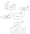
- FIG. 22 is a block diagram showing an example of the configuration of a gNB 2 according to the above-mentioned embodiment.
- the gNB 2 includes a main RF transceiver 2201, a network interface 2203, a processor 2204, and a memory 2205.
- the main RF transceiver 2201 performs analog RF signal processing to communicate with UEs including UE 1.
- the RF transceiver 2201 may include multiple transceivers.
- the RF transceiver 2201 is coupled to the antenna array 2202 and the processor 2204.
- the RF transceiver 2201 receives modulation symbol data from the processor 2204, generates a transmit RF signal, and provides the transmit RF signal to the antenna array 2202.
- the RF transceiver 2201 also generates a baseband receive signal based on the receive RF signal received by the antenna array 2202, and provides the baseband receive signal to the processor 2204.
- the RF transceiver 2201 may include an analog beamformer circuit for beamforming.
- the analog beamformer circuitry includes, for example, multiple phase shifters and multiple power amplifiers.
- the network interface 2203 is used to communicate with network nodes (e.g., other gNBs and RAN nodes, as well as control and forwarding nodes of the core network).
- the network interface 2203 may include, for example, an IEEE 802.3 series compliant network interface card (NIC).
- NIC network interface card
- the processor 2204 performs digital baseband signal processing (data plane processing) and control plane processing for wireless communication.
- the processor 2204 may include multiple processors.
- the processor 2204 may include a modem processor (e.g., DSP) that performs digital baseband signal processing and a protocol stack processor (e.g., CPU or MPU) that performs control plane processing.
- DSP digital baseband signal processing
- protocol stack processor e.g., CPU or MPU
- digital baseband signal processing by processor 2204 may include signal processing of SDAP, PDCP, Radio RLC, MAC, and PHY layers.
- control plane processing by processor 2204 may include processing of NAS messages, RRC messages, MAC CEs, and DCIs.
- the processor 2204 may include a digital beamformer module for beamforming.
- the digital beamformer module may include a MIMO encoder and a precoder.
- the memory 2205 is composed of a combination of volatile memory and non-volatile memory.
- the volatile memory is, for example, SRAM or DRAM, or a combination of these.
- the non-volatile memory is MROM, EEPROM, flash memory, or a hard disk drive, or any combination of these.
- the memory 2205 may include storage located remotely from the processor 2204. In this case, the processor 2204 may access the memory 2205 via the network interface 2203 or an I/O interface not shown.
- the memory 2205 may store one or more software modules (computer programs) 2206 including instructions and data for performing processing by the gNB 2 as described in the above-mentioned embodiments.
- the processor 2204 may be configured to read and execute the software modules 2206 from the memory 2205 to perform the processing by the gNB 2 as described in the above-mentioned embodiments.
- the LP-WUS transmitter 1810 has the function of transmitting low power wake-up related signals, such as LP-WUS and LP-SS.
- the LP-WUS transmitter 1810 is coupled to the processor 2204.
- gNB 2 may not include RF transceiver 2201 (and antenna array 2202) and LP-WUS transmitter 1810.
- each of the processors of the UE 1 and gNB 2 in the above-mentioned embodiments can execute one or more programs including instructions for causing a computer to perform the algorithms described with reference to the drawings.
- the programs include instructions (or software code) for causing a computer to perform one or more functions described in the embodiments when loaded into the computer.
- the programs may be stored on a non-transitory computer-readable medium or a tangible storage medium.
- computer-readable media or tangible storage media include random-access memory (RAM), read-only memory (ROM), flash memory, solid-state drive (SSD) or other memory technology, CD-ROM, digital versatile disk (DVD), Blu-ray (registered trademark) disk or other optical disk storage, magnetic cassette, magnetic tape, magnetic disk storage or other magnetic storage device.
- RAM random-access memory
- ROM read-only memory
- SSD solid-state drive
- CD-ROM compact disc-read-only memory
- DVD digital versatile disk
- Blu-ray (registered trademark) disk or other optical disk storage magnetic cassette, magnetic tape, magnetic disk storage or other magnetic storage device.
- the programs may be transmitted on a transitory computer-readable medium or a communication medium.
- transitory computer-readable media or communication media include electrical, optical, acoustic, or other forms of propagated signals.
- appendices may be described as, but are not limited to, the following appendices.
- Some or all of the elements (e.g., configurations and functions) described in appendices directed to devices may naturally be described as appendices directed to methods and programs.
- some or all of the elements described in appendices 9-13 that are subordinate to appendices 8 may be described as appendices that are subordinate to appendices 15 and 17 due to the same subordinate relationship as appendices 9-13.
- Some or all of the elements described in any appendice may be applied to various hardware, software, recording means for recording software, systems, and methods.
- (Appendix 1) A main transceiver; A low power wake-up receiver; means for recording Minimization of Drive Tests (MDT) measurement results including measurements of low power wake-up related signals using the low power wake-up receiver while at least the primary transceiver is in the ultra-deep sleep power state;
- a wireless terminal comprising: (Appendix 2) the recording means is adapted to record measurements of the low power wake-up related signals when the primary transceiver enters the ultra deep sleep power state and/or when the primary transceiver wakes up from the ultra deep sleep power state. 2.
- the method further comprises: indicating, in a report of the MDT measurement result to a network, that the MDT measurement result relates to the measurement of the low power consumption wake-up related signal; 3.
- the wireless terminal of claim 1 or 2. (Appendix 4) means for receiving an MDT measurement configuration from a network, the MDT measurement configuration including a configuration or indication of measurement logging of the low power wakeup related signal; the recording means being adapted to record measurements of the low power wake-up related signals in response to receiving the MDT measurement configuration. 4.
- the primary transceiver is used for signal transmission and reception, including a Physical Uplink Control Channel (PUCCH) transmission, a Physical Uplink Shared Channel (PUSCH) transmission, a Physical Downlink Control Channel (PDCCH) reception, and a Physical Downlink Shared Channel (PDSCH) reception; the primary transceiver is not used to receive the low power wakeup related signal; the low power wakeup receiver is used to receive the low power wakeup related signals while at least the primary transceiver is in the ultra deep sleep power state. 5.
- PUCCH Physical Uplink Control Channel
- PUSCH Physical Uplink Shared Channel
- PDCH Physical Downlink Control Channel
- PDSCH Physical Downlink Shared Channel
- the recording means is adapted to record a measurement result of a Synchronization Signal (SS)/Physical Broadcast Channel (PBCH) block (SSB) for MDT in addition to the measurement result of the low power consumption wake-up related signal.
- SS Synchronization Signal
- PBCH Physical Broadcast Channel
- SSB Synchronization Signal
- the MDT is a Logged MDT.
- Appendix 8) means for transmitting Minimization of Drive Tests (MDT) measurement configuration to a wireless terminal, the measurement configuration including a setting or indication of measurement logging of low power wake-up related signals; Radio Access Network (RAN) nodes.
- MDT Minimization of Drive Tests
- the MDT measurement configuration causes the wireless terminal to record MDT measurements including measurements of the low power wake-up related signals using a low power wake-up receiver of the wireless terminal while at least a primary transceiver of the wireless terminal is in an ultra-deep sleep power state.
- the RAN node of claim 8. the MDT measurement configuration causes the wireless terminal to record measurements of the low power wake-up related signals when the primary transceiver enters the ultra deep sleep power state and/or when the primary transceiver wakes up from the ultra deep sleep power state. 10.
- the primary transceiver is used for signal transmission and reception, including a Physical Uplink Control Channel (PUCCH) transmission, a Physical Uplink Shared Channel (PUSCH) transmission, a Physical Downlink Control Channel (PDCCH) reception, and a Physical Downlink Shared Channel (PDSCH) reception;
- the primary transceiver is not used to receive the low power wakeup related signal;
- the low power wakeup receiver is used to receive the low power wakeup related signals while at least the primary transceiver is in the ultra deep sleep power state.
- the MDT measurement results include, in addition to the measurement results of the low power consumption wake-up related signals, measurement results of Synchronization Signal (SS)/Physical Broadcast Channel (PBCH) block (SSB), 12.
- the MDT is a Logged MDT. 13.
- (Appendix 14) recording Minimization of Drive Tests (MDT) measurement results including measurement results of low power wake-up related signals using a low power wake-up receiver while at least the primary transceiver is in the ultra-deep sleep power state; A method performed by a wireless terminal.
- MDT Minimization of Drive Tests
- the method is performed by a Radio Access Network (RAN) node.
- (Appendix 16) A program for causing a computer to perform a method for a wireless terminal, comprising: The method includes recording Minimization of Drive Tests (MDT) measurements including measurements of low power wake-up related signals using a low power wake-up receiver while at least a primary transceiver is in an ultra-deep sleep power state. program. (Appendix 17) 1.
- MDT Minimization of Drive Tests
- a program for causing a computer to perform a method for a Radio Access Network (RAN) node comprising: The method comprises transmitting a Minimization of Drive Tests (MDT) measurement configuration to a wireless terminal, the measurement configuration including configuration for measurement logging of low power wake-up related signals; program.
- MDT Minimization of Drive Tests
- (Appendix 18) A main transceiver; A low power wake-up receiver; means for storing measurement results for IDLE/INACTIVE measurement reporting, including measurements of low power wake-up related signals using the low power wake-up receiver while at least the primary transceiver is in the ultra-deep sleep power state; and A wireless terminal comprising: (Appendix 19) means for indicating in the IDLE/INACTIVE measurement reporting to a network that the measurement results for the IDLE/INACTIVE measurement reporting relate to measurements of the low power wake-up related signals; 19. The wireless terminal of claim 18.
- the wireless terminal of claim 18 or 19. The receiving means is configured to receive the information via a Radio Resource Control (RRC) message dedicated to the wireless terminal or via system information common within a cell. 21. The wireless terminal of claim 20.
- RRC Radio Resource Control
- the receiving means is configured to receive the information via a RRCRelease message. 21. The wireless terminal of claim 20.
- the receiving means is configured to receive the information via a System Information Block type 1 (SIB1) or a SIB type 11 (SIB11); 21.
- SIB1 System Information Block type 1
- SIB11 SIB type 11
- the primary transceiver is used for signal transmission and reception, including a Physical Uplink Control Channel (PUCCH) transmission, a Physical Uplink Shared Channel (PUSCH) transmission, a Physical Downlink Control Channel (PDCCH) reception, and a Physical Downlink Shared Channel (PDSCH) reception; the primary transceiver is not used to receive the low power wakeup related signal; the low power wakeup receiver is used to receive the low power wakeup related signals while at least the primary transceiver is in the ultra deep sleep power state.
- PUCCH Physical Uplink Control Channel
- PUSCH Physical Uplink Shared Channel
- PDCH Physical Downlink Control Channel
- PDSCH Physical Downlink Shared Channel
- the wireless terminal according to any one of appendix 18 to 23.
- (Appendix 25) means for transmitting information to a wireless terminal indicating that the IDLE/INACTIVE measurements include measurements of low power wake-up related signals; Radio Access Network (RAN) nodes.
- the information causes the wireless terminal to store measurement results for IDLE/INACTIVE measurement reporting, including measurements of the low power wake-up related signals using a low power wake-up receiver of the wireless terminal while at least a primary transceiver of the wireless terminal is in an ultra-deep sleep power state; 26.
- the transmitting means is configured to transmit the information via a dedicated Radio Resource Control (RRC) message to the wireless terminal or via common system information within a cell.
- RRC Radio Resource Control
- the means for transmitting is configured to transmit the information via an RRCRelease message.
- the transmitting means is configured to transmit the information via a System Information Block type 1 (SIB1) or a SIB type 11 (SIB11); 27.
- SIB1 System Information Block type 1
- SIB11 SIB type 11
- the primary transceiver is used for signal transmission and reception, including a Physical Uplink Control Channel (PUCCH) transmission, a Physical Uplink Shared Channel (PUSCH) transmission, a Physical Downlink Control Channel (PDCCH) reception, and a Physical Downlink Shared Channel (PDSCH) reception;
- the primary transceiver is not used to receive the low power wakeup related signal;
- the low power wakeup receiver is used to receive the low power wakeup related signals while at least the primary transceiver is in the ultra deep sleep power state.
- (Appendix 31) storing measurement results for IDLE/INACTIVE measurement reporting, including measurement results of low power wake-up related signals using the low power wake-up receiver while at least the primary transceiver is in the ultra-deep sleep power state;
- a method performed by a wireless terminal. (Appendix 32) transmitting information indicating that the low power consumption wake-up related signal is a target for IDLE/INACTIVE measurement to the wireless terminal; The method is performed by a Radio Access Network (RAN) node.
- RAN Radio Access Network
- a program for causing a computer to perform a method for a wireless terminal comprising: The method includes storing measurement results for IDLE/INACTIVE measurement reporting, the measurement results including measurements of low power wake-up related signals using a low power wake-up receiver while at least a primary transceiver is in an ultra-deep sleep power state. program.
- (Appendix 34) 1. A program for causing a computer to perform a method for a Radio Access Network (RAN) node, comprising: The method comprises transmitting to the wireless terminal information indicating that the low power consumption wake-up related signal is subject to IDLE/INACTIVE measurement. program.
- RAN Radio Access Network
- a main transceiver A low power wake-up receiver; means for performing a Small Data Transmission (SDT) procedure using the primary transceiver that has woken up from an ultra-deep sleep power state by skipping a comparison between a first measurement value obtained from a Synchronization Signal (SS)/Physical Broadcast Channel (PBCH) block (SSB) measurement and a first threshold;
- a wireless terminal comprising: (Appendix 36) the performing means being adapted to perform a comparison between a second measurement value obtained from measuring a low power wake-up related signal using the low power wake-up receiver and a second threshold value to determine whether a condition for initiating the SDT procedure is met. 36. The wireless terminal of claim 35.
- (Appendix 37) means for receiving first setting information indicating the second threshold value from a network; 37.
- 38. A wireless terminal according to any one of appendix 35 to 37.
- the random access resource selection further comprises means for selecting an SSB or a Physical Random Access Channel (PRACH) opportunity based on a second measurement value obtained from measuring a low power wakeup related signal using the low power wakeup receiver.
- PRACH Physical Random Access Channel
- the second setting information indicating the correspondence between the plurality of beams or the plurality of random access opportunities of the SSB and the plurality of beams of the low power consumption wake-up related signal is further provided with a means for receiving from a network.
- the random access resource selection further comprises a means for selecting an arbitrary SSB; 39.
- (Appendix 42) means for receiving third setting information indicating that a comparison between the first measurement value and the first threshold value is skipped; the initiating means being adapted to skip a comparison of the first measurement value with the first threshold in response to receiving the third configuration information. 42.
- the wireless terminal according to any one of appendixes 35 to 41.
- the wireless terminal according to any one of appendixes 35 to 42.
- the SDT procedure is a procedure in which the radio terminal can transmit data or signaling while remaining in a Radio Resource Control (RRC)_INACTIVE state without transitioning to an RRC_CONNECTED state.
- RRC Radio Resource Control
- the wireless terminal according to any one of appendixes 35 to 43.
- the primary transceiver is used for signal transmission and reception, including a Physical Uplink Control Channel (PUCCH) transmission, a Physical Uplink Shared Channel (PUSCH) transmission, a Physical Downlink Control Channel (PDCCH) reception, and a Physical Downlink Shared Channel (PDSCH) reception; the primary transceiver is not used to receive low power wake-up related signals; the low power wakeup receiver is used to receive the low power wakeup related signals while at least the primary transceiver is in the ultra deep sleep power state.
- PUCCH Physical Uplink Control Channel
- PUSCH Physical Uplink Shared Channel
- PDCH Physical Downlink Control Channel
- PDSCH Physical Downlink Shared Channel
- (Appendix 46) means for transmitting configuration information to a wireless terminal, the configuration information indicating that a comparison between a first measurement value obtained from a Synchronization Signal (SS)/Physical Broadcast Channel (PBCH) block (SSB) measurement and a first threshold value is skipped in determining whether a condition for initiating a Small Data Transmission (SDT) procedure is satisfied; Radio Access Network (RAN) nodes.
- the configuration information causes the wireless terminal to perform the SDT procedure with a primary transceiver that has woken up from an ultra-deep sleep power state by skipping a comparison of the first measurement value with the first threshold value. 47.
- (Appendix 48) means for transmitting setting information indicating a second threshold value to the wireless terminal; the second threshold causes the wireless terminal to compare a second measurement obtained from measuring a low power wake-up related signal using a low power wake-up receiver to a second threshold to determine whether a condition for initiating the SDT procedure is met.
- (Appendix 49) means for transmitting setting information indicating a third threshold value to the wireless terminal; The third threshold is used in the random access resource selection to select an SSB or a Physical Random Access Channel (PRACH) opportunity based on a second measurement value obtained from measuring a low power wake-up related signal using a low power wake-up receiver of the wireless terminal.
- PRACH Physical Random Access Channel
- a method performed by a wireless terminal having a primary transceiver and a low power wake-up receiver comprising: performing a Small Data Transmission (SDT) procedure using the primary transceiver that has woken up from an ultra-deep sleep power state by skipping a comparison between a first measurement value obtained from a Synchronization Signal (SS)/Physical Broadcast Channel (PBCH) block (SSB) measurement and a first threshold value; method.
- SDT Small Data Transmission
- (Appendix 51) transmitting configuration information to the wireless terminal indicating that a comparison between a first measurement value obtained from a Synchronization Signal (SS)/Physical Broadcast Channel (PBCH) block (SSB) measurement and a first threshold is skipped in determining whether a condition for initiating a Small Data Transmission (SDT) procedure is satisfied;
- the method is performed by a Radio Access Network (RAN) node.
- RAN Radio Access Network
- a program for causing a computer to perform a method for a wireless terminal having a primary transceiver and a low power consumption wake-up receiver comprising: the method comprising: performing a Small Data Transmission (SDT) procedure with the primary transceiver waking up from an ultra-deep sleep power state by skipping a comparison of a first measurement value obtained from a Synchronization Signal (SS)/Physical Broadcast Channel (PBCH) block (SSB) measurement to a first threshold value; program. (Appendix 53) 1.
- SDT Small Data Transmission
- a program for causing a computer to perform a method for a Radio Access Network (RAN) node comprising: The method includes transmitting configuration information to the wireless terminal, the configuration information indicating that a comparison between a first measurement value obtained from a Synchronization Signal (SS)/Physical Broadcast Channel (PBCH) block (SSB) measurement and a first threshold is skipped in determining whether a condition for initiating a Small Data Transmission (SDT) procedure is met.
- SS Synchronization Signal
- PBCH Physical Broadcast Channel
- SDT Small Data Transmission
- a main transceiver A low power wake-up receiver; means for attempting to measure or detect a low power wake-up related signal of a neighboring cell supporting an intended network slice if a quality of a low power wake-up related signal of a serving cell or a serving cell frequency measured using the low power wake-up receiver degrades while the primary transceiver is in the ultra-deep sleep power state;
- a wireless terminal comprising: (Appendix 55) When the quality of the low power wake-up related signal of a neighboring cell supporting the intended network slice is insufficient or a neighboring cell supporting the intended network slice is not detected, the method further comprises: waking up the primary transceiver and initiating cell reselection utilizing Synchronization Signal (SS)/Physical Broadcast Channel (PBCH) block (SSB) measurements using the primary transceiver.
- SS Synchronization Signal
- PBCH Physical Broadcast Channel
- the primary transceiver is used for signal transmission and reception, including a Physical Uplink Control Channel (PUCCH) transmission, a Physical Uplink Shared Channel (PUSCH) transmission, a Physical Downlink Control Channel (PDCCH) reception, and a Physical Downlink Shared Channel (PDSCH) reception; the primary transceiver is not used to receive the low power wakeup related signal; the low power wakeup receiver is used to receive the low power wakeup related signals while at least the primary transceiver is in the ultra deep sleep power state.
- PUCCH Physical Uplink Control Channel
- PUSCH Physical Uplink Shared Channel
- PDCH Physical Downlink Control Channel
- PDSCH Physical Downlink Shared Channel
- the neighboring cell supporting the intended network slice is a cell supporting a Network Slice Access Stratum AS Group (NSAG) containing the intended Single Network Slice Selection Assistance Information (S-NSSAI), 57.
- (Appendix 58) 1.
- a method performed by a wireless terminal having a primary transceiver and a low power wake-up receiver comprising: and if a quality of a low power wake-up related signal of a serving cell or a serving cell frequency measured using the low power wake-up receiver degrades while the primary transceiver is in the ultra-deep sleep power state, attempting to measure or detect a low power wake-up related signal of a neighboring cell supporting the intended network slice. method.
- a program for causing a computer to perform a method for a wireless terminal having a primary transceiver and a low power consumption wake-up receiver comprising: The method comprises attempting to measure or detect low power wake-up related signals of a neighboring cell supporting the intended network slice if a quality of a low power wake-up related signal of a serving cell or serving cell frequency measured using a low power wake-up receiver degrades while the primary transceiver is in an ultra-deep sleep power state. program.
- (Appendix 60) A main transceiver; A low power wake-up receiver; if there is a frequency with a higher priority for cell reselection than a serving cell frequency, attempting, while the primary transceiver is in an ultra-deep sleep power state, to measure or detect low power wake-up related signals of a neighboring cell supporting the intended network slice, using the low power wake-up receiver; A wireless terminal comprising: (Appendix 61) When the quality of the low power wake-up related signal of a neighboring cell supporting the intended network slice is insufficient or a neighboring cell supporting the intended network slice is not detected, the method further comprises: waking up the primary transceiver and initiating cell reselection utilizing Synchronization Signal (SS)/Physical Broadcast Channel (PBCH) block (SSB) measurements using the primary transceiver.
- SS Synchronization Signal
- PBCH Physical Broadcast Channel
- the primary transceiver is used for signal transmission and reception, including a Physical Uplink Control Channel (PUCCH) transmission, a Physical Uplink Shared Channel (PUSCH) transmission, a Physical Downlink Control Channel (PDCCH) reception, and a Physical Downlink Shared Channel (PDSCH) reception; the primary transceiver is not used to receive the low power wakeup related signal; the low power wakeup receiver is used to receive the low power wakeup related signals while at least the primary transceiver is in the ultra deep sleep power state.
- the wireless terminal of claim 60 or 61 The wireless terminal of claim 60 or 61.
- the neighboring cell supporting the intended network slice is a cell supporting a Network Slice Access Stratum AS Group (NSAG) containing the intended Single Network Slice Selection Assistance Information (S-NSSAI), 63.
- S-NSSAI Single Network Slice Selection Assistance Information
- a method performed by a wireless terminal having a primary transceiver and a low power wake-up receiver comprising: If there is a frequency with a higher priority for cell reselection than a serving cell frequency, attempting, while the primary transceiver is in an ultra-deep sleep power state, to measure or detect a low power wake-up related signal of a neighboring cell supporting the intended network slice using the low power wake-up receiver on the higher priority frequency.
- Appendix 65 1.
- a program for causing a computer to perform a method for a wireless terminal having a primary transceiver and a low power consumption wake-up receiver comprising: If there is a frequency with a higher priority for cell reselection than a serving cell frequency, attempting, while the primary transceiver is in an ultra-deep sleep power state, to measure or detect a low power wake-up related signal of a neighboring cell supporting the intended network slice using the low power wake-up receiver on the higher priority frequency.
- UE User Equipment
- gNB 11 Main Radio (MR) 12 Low Power Wake-up Radio (LR) 21
- Baseband processor 2104
- Application processor 2106
- Memory 2107
- Modules 2204 processor 2205 memory 2206 modules
Landscapes
- Engineering & Computer Science (AREA)
- Computer Networks & Wireless Communication (AREA)
- Signal Processing (AREA)
- Mobile Radio Communication Systems (AREA)
Priority Applications (1)
| Application Number | Priority Date | Filing Date | Title |
|---|---|---|---|
| JP2025542747A JPWO2025047097A1 (https=) | 2023-08-30 | 2024-07-01 |
Applications Claiming Priority (2)
| Application Number | Priority Date | Filing Date | Title |
|---|---|---|---|
| JP2023-139771 | 2023-08-30 | ||
| JP2023139771 | 2023-08-30 |
Publications (1)
| Publication Number | Publication Date |
|---|---|
| WO2025047097A1 true WO2025047097A1 (ja) | 2025-03-06 |
Family
ID=94818673
Family Applications (1)
| Application Number | Title | Priority Date | Filing Date |
|---|---|---|---|
| PCT/JP2024/023713 Pending WO2025047097A1 (ja) | 2023-08-30 | 2024-07-01 | 無線端末、無線アクセスネットワークノード、及びこれらの方法 |
Country Status (2)
| Country | Link |
|---|---|
| JP (1) | JPWO2025047097A1 (https=) |
| WO (1) | WO2025047097A1 (https=) |
Cited By (1)
| Publication number | Priority date | Publication date | Assignee | Title |
|---|---|---|---|---|
| WO2026051441A1 (en) * | 2025-05-21 | 2026-03-12 | Lenovo (Beijing) Limited | Methods and apparatuses of a minimization of drive tests (mdt) mechanism for low power wake up radio (lp-wur) |
Citations (6)
| Publication number | Priority date | Publication date | Assignee | Title |
|---|---|---|---|---|
| WO2011093665A2 (en) * | 2010-01-28 | 2011-08-04 | Lg Electronics Inc. | Method of performing a minimization of drive test (mdt) in wireless communication system |
| WO2023055700A1 (en) * | 2021-09-30 | 2023-04-06 | Interdigital Patent Holdings, Inc. | Methods and apparatus for rrm measurement and paging reliability using low power wake-up receiver for wireless systems |
| US20230164636A1 (en) * | 2021-11-22 | 2023-05-25 | Parsa Wireless Communications Llc | Mbs configuration optimization based on quality of experience feedback |
| US20230209463A1 (en) * | 2020-05-26 | 2023-06-29 | FG Innovation Company Limited | Method of performing a power saving operation and related device |
| WO2023144025A1 (en) * | 2022-01-28 | 2023-08-03 | Sony Group Corporation | Low-power wake-up receiver for devices with low latency |
| JP2023139771A (ja) | 2022-03-22 | 2023-10-04 | トヨタ自動車株式会社 | 内燃機関の制御装置 |
-
2024
- 2024-07-01 JP JP2025542747A patent/JPWO2025047097A1/ja active Pending
- 2024-07-01 WO PCT/JP2024/023713 patent/WO2025047097A1/ja active Pending
Patent Citations (6)
| Publication number | Priority date | Publication date | Assignee | Title |
|---|---|---|---|---|
| WO2011093665A2 (en) * | 2010-01-28 | 2011-08-04 | Lg Electronics Inc. | Method of performing a minimization of drive test (mdt) in wireless communication system |
| US20230209463A1 (en) * | 2020-05-26 | 2023-06-29 | FG Innovation Company Limited | Method of performing a power saving operation and related device |
| WO2023055700A1 (en) * | 2021-09-30 | 2023-04-06 | Interdigital Patent Holdings, Inc. | Methods and apparatus for rrm measurement and paging reliability using low power wake-up receiver for wireless systems |
| US20230164636A1 (en) * | 2021-11-22 | 2023-05-25 | Parsa Wireless Communications Llc | Mbs configuration optimization based on quality of experience feedback |
| WO2023144025A1 (en) * | 2022-01-28 | 2023-08-03 | Sony Group Corporation | Low-power wake-up receiver for devices with low latency |
| JP2023139771A (ja) | 2022-03-22 | 2023-10-04 | トヨタ自動車株式会社 | 内燃機関の制御装置 |
Non-Patent Citations (15)
| Title |
|---|
| "3rd Generation Partnership Project; Technical Specification Group Radio Access Network; Study on low-power wake up signal and receiver for NR (Release 18", 3GPP TR 38.869 V0.2.0, May 2023 (2023-05-01) |
| APPLE: "RAN2 impact on LP-WUS in IDLE/INACTIVE state", 3GPP TSG-RAN WG2 MEETING #122, INCHEON, 22 May 2023 (2023-05-22) |
| ERICSSON: "LP-WUS/WUR for RRC Idle and Inactive", 3GPP TSG-RAN WG2 MEETING #122, 22 May 2023 (2023-05-22) |
| HUAWEIHISILICON: "MR/LR UE behaviours for paging and mobility in RRC_IDLE/INACTIVE state", 3GPP TSG-RAN WG2 MEETING #123, 21 August 2023 (2023-08-21) |
| HUAWEIHISILICON: "MR/LR UE behaviours for paging and mobility in RRC_IDLE/INACTIVE state", R2-2306060, 3GPP TSG-RAN WG2 MEETING #122, 22 May 2023 (2023-05-22) |
| NEC: "Discussion on the considerations for LPWUS in RRC_IDLE INACTIVE", R2-2304988, 3GPP TSG-RAN WG2, 22 May 2023 (2023-05-22) |
| NEC: "Low-power Wake-up Signal and Receiver for NR", 3GPP TSG RAN REL-19 WORKSHOP, 15 June 2023 (2023-06-15) |
| QUALCOMM INCORPORATED: "Use of low-power receiver in idle mode procedures", R2-2304714, 3GPP TSG-RAN WG2 MEETING #122, 22 May 2023 (2023-05-22) |
| SONY: "Considerations on LP-WUR in RRC Idle/Inactive mode", R2-2305528, 3GPP TSG-RAN WG2 MEETING #122, 22 May 2023 (2023-05-22) |
| VIVO: "Discussion on LP-WUS/WUR in RRC_IDLE/INACTIVE", R2-2304923, 3GPP TSG-RAN WG2 MEETING, 22 May 2023 (2023-05-22) |
| VIVO: "Revised SID: Study on low-power Wake-up Signal and Receiver for NR", RP-222644, 3GPP TSG RAN MEETING #97E, 12 September 2022 (2022-09-12) |
| VIVO: "Updated scope clarification of Rel-18 SI on LP-WUS/WUR", R2-2305745, 3GPP TSG-RAN WG2 MEETING #122 |
| VIVO: "Work Plan for Rel-18 SI on LP-WUS/WUR", R2-2305746, 3GPP TSG-RAN WG2 MEETING #122, 22 May 2023 (2023-05-22) |
| XIAOMI COMMUNICATIONS: "General considerations on the procedure for RRC_IDLE_INACTIVE", R2-2305000, 3GPP TSG-RAN WG2 MEETING #122, 22 May 2023 (2023-05-22) |
| ZTE CORPORATIONSANECHIPS: "RAN2 impacts of LP-WUS in idle or inactive mode", 3GPP TSG-RAN WG2 MEETING #122, 22 May 2023 (2023-05-22) |
Cited By (1)
| Publication number | Priority date | Publication date | Assignee | Title |
|---|---|---|---|---|
| WO2026051441A1 (en) * | 2025-05-21 | 2026-03-12 | Lenovo (Beijing) Limited | Methods and apparatuses of a minimization of drive tests (mdt) mechanism for low power wake up radio (lp-wur) |
Also Published As
| Publication number | Publication date |
|---|---|
| JPWO2025047097A1 (https=) | 2025-03-06 |
Similar Documents
| Publication | Publication Date | Title |
|---|---|---|
| US20250392973A1 (en) | Wtru mobility and cell reselection in energy savings networks | |
| CN107078890B (zh) | 无线电信网络中的网络节点和方法 | |
| US10694493B2 (en) | Paging and DRX enhancements for eMTC-U (IOT-U) | |
| US12446070B2 (en) | Systems and methods for UE operation in presence of CCA | |
| JP6925438B2 (ja) | Mtc機器の電力消費を抑えるシグナリング指標 | |
| CN110249570B (zh) | 基于另一个参考信号带宽来控制极简载波上的小区特定参考信号(crs)带宽 | |
| CN111316752B (zh) | 无线电网络节点、无线设备以及其中执行的方法 | |
| US10917917B2 (en) | Method for transmitting random access messages on non-anchor carriers | |
| US11622285B2 (en) | Performing measurements in multicarrier operation | |
| CN111587588A (zh) | 用于更新系统信息的方法和装置 | |
| CN113875183B (zh) | 发送和接收指示 | |
| CN108353303A (zh) | 在不连续活动下测量多个载波 | |
| US20230079204A1 (en) | Wireless device grouping mechanisms and network configuration for false paging reduction | |
| CN110291735B (zh) | 控制节点、测量节点及用于其的方法 | |
| US11271704B2 (en) | Radio network node, wireless device and methods performed therein | |
| CN114246003B (zh) | 使用基于l1指示的跨时隙调度的nr ue省电 | |
| CN118251954A (zh) | 用于接入长周期小区以进行网络节能的方法及装置 | |
| JP2025529653A (ja) | 省エネルギー化ネットワークにおけるwtru到達可能性 | |
| JP2021513801A (ja) | 狭帯域測位参照信号設定 | |
| US20230262538A1 (en) | Method and apparatus for recording information in mobile communication system | |
| WO2025047097A1 (ja) | 無線端末、無線アクセスネットワークノード、及びこれらの方法 | |
| WO2025047096A1 (ja) | 無線アクセスネットワークノード、無線端末、及びこれらの方法 | |
| WO2024171587A1 (ja) | 無線端末、無線アクセスネットワークノード、及びこれらの方法 | |
| HK1237152A1 (en) | Network node and method in a wireless telecommunications network | |
| HK1237152B (zh) | 无线电信网络中的网络节点和方法 |
Legal Events
| Date | Code | Title | Description |
|---|---|---|---|
| 121 | Ep: the epo has been informed by wipo that ep was designated in this application |
Ref document number: 24859142 Country of ref document: EP Kind code of ref document: A1 |
|
| ENP | Entry into the national phase |
Ref document number: 2025542747 Country of ref document: JP Kind code of ref document: A |
|
| WWE | Wipo information: entry into national phase |
Ref document number: 2025542747 Country of ref document: JP |
|
| WWE | Wipo information: entry into national phase |
Ref document number: 2024859142 Country of ref document: EP |