WO2025041298A1 - ロボット、及び経路設定方法 - Google Patents
ロボット、及び経路設定方法 Download PDFInfo
- Publication number
- WO2025041298A1 WO2025041298A1 PCT/JP2023/030305 JP2023030305W WO2025041298A1 WO 2025041298 A1 WO2025041298 A1 WO 2025041298A1 JP 2023030305 W JP2023030305 W JP 2023030305W WO 2025041298 A1 WO2025041298 A1 WO 2025041298A1
- Authority
- WO
- WIPO (PCT)
- Prior art keywords
- point
- registered
- probe
- order
- robot
- Prior art date
- Legal status (The legal status is an assumption and is not a legal conclusion. Google has not performed a legal analysis and makes no representation as to the accuracy of the status listed.)
- Pending
Links
Images


Classifications
-
- B—PERFORMING OPERATIONS; TRANSPORTING
- B25—HAND TOOLS; PORTABLE POWER-DRIVEN TOOLS; MANIPULATORS
- B25J—MANIPULATORS; CHAMBERS PROVIDED WITH MANIPULATION DEVICES
- B25J9/00—Program-controlled manipulators
- B25J9/16—Program controls
- B25J9/1656—Program controls characterised by programming, planning systems for manipulators
Definitions
- This disclosure relates to a robot and a path setting method.
- a robot of this type includes a robot arm that holds an ultrasound probe and moves the ultrasound probe along the body surface of a subject, a memory unit that stores instruction trajectory information for moving the ultrasound probe by the robot arm, and a robot arm control unit that controls the drive of the robot arm so as to move the ultrasound probe according to the stored instruction trajectory information (see, for example, Patent Document 1).
- the robot arm is controlled to move the ultrasound probe according to the instruction trajectory information stored in the memory unit.
- the operator may have to adjust the points that have already been registered with the points to be newly registered. As a result, there is a problem in that the workload on the operator increases.
- This disclosure was made in consideration of the above problems, and aims to provide a robot and a path setting method that can reduce the burden of registering the positions to which the probe is moved.
- this specification discloses a robot that includes an arm capable of holding a probe of an ultrasound device and a control device that controls the operation of the arm, and the control device executes a storage process that changes the position of the probe in response to an operation by an operator and stores the changed position of the probe in a storage device as a registered point, and a route setting process that rearranges the order of the multiple registered points stored in the storage device by the storage process based on a sorting condition for rearranging the order of the registered points, and sets a route for moving the probe between the multiple registered points in accordance with the rearranged order.
- the robot and route setting method disclosed herein rearranges the order of registered points based on sorting conditions and sets routes connecting the registered points. This reduces the operator's workload of adjusting registered points that have already been registered and newly registered points. It also reduces the burden of registering positions to which the probe is moved as registered points.
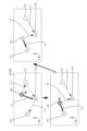
- FIG. 1 is an external perspective view of a robot system according to an embodiment of the present invention.
- FIG. 1 is a schematic diagram of a robot. An enlarged view of a portion of the robot including the hand. An enlarged view of a portion of the robot including the hand.
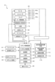
- FIG. 2 is a block diagram showing electrical connections in the robot system.
- FIG. 4 is an explanatory diagram showing the movement direction of an ultrasonic probe.
- FIG. 4 is an explanatory diagram for explaining a mode transition from power-on to power-off of the robot.
- FIG. 4 is an explanatory diagram showing an example of an operation mode screen displayed on an operation panel.
- FIG. 13 shows a selection screen for selecting types A to D.
- FIG. 13 is a diagram showing the relationship between types A to D and the sorting priority order in each axial direction.
- FIG. 4 is a diagram for explaining a route setting process.
- FIG. 4 is a diagram for explaining a route setting process.
- FIG. 4 is a diagram for explaining a route setting process.
- FIG. 4 is a diagram for explaining a route setting process.
- FIG. 4 is a diagram for explaining a route setting process.
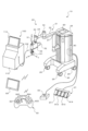
- Fig. 1 is an external perspective view of a robot system 10 according to this embodiment.
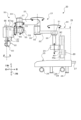
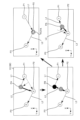
- Fig. 2 is a schematic diagram of the robot 20.
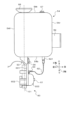
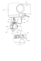
- Figs. 3 and 4 are partial enlarged views of the robot 20 including the hand unit 60.
- Fig. 5 is a block diagram showing the electrical connections of the robot system 10.
- the forward/backward direction is referred to as the X-axis direction, the left/right direction as the Y-axis direction, and the up/down direction as the Z-axis direction, based on the direction as seen by an operator operating the operation panel 90 of the robot 20.
- the robot system 10 of this embodiment includes a robot 20 having a multi-joint robot arm 21, a foot switch 91, an ESR controller 92, a tablet terminal 93, and an emergency stop switch 94.
- the robot system 10 holds an ultrasonic probe 101 of an ultrasonic device 100 at the tip of the robot arm 21, and controls the robot 20 to move while pressing the ultrasonic probe 101 against the body surface of the human body, thereby causing the ultrasonic device 100 to obtain an ultrasonic echo image of the human body.
- the robot system 10 is used as an ultrasonic echo guide during surgery such as catheter surgery.
- An operator (surgeon) who operates a catheter guidewire instructs the robot 20 to press the ultrasonic probe 101 against the body surface of the human body (patient), and advances the guidewire while recognizing the positional relationship between the tip of the guidewire and the blood vessel from the obtained ultrasonic echo image, thereby allowing the guidewire to accurately pass through the center of the occlusion or stenosis of the blood vessel.
- the operator manually operates the robot arm 21 and places the ultrasound probe 101 held by the robot arm 21 on the patient, checking the acquired ultrasound echo image, while determining the points (images) to be reproduced during surgery and performing direct teaching to register them in the robot 20 (robot control device 80).
- the ultrasound device 100 includes an ultrasound probe 101 and an ultrasound device main body 110 connected to the ultrasound probe 101 via a cable 102.
- the ultrasound device main body 110 includes an ultrasound diagnosis control unit 111 that controls the entire device, an image processing unit 112 that processes the received signal from the ultrasound probe 101 to generate an ultrasound echo image, an image display unit 113 that displays the ultrasound echo image, and various operation switches (not shown).
- the ultrasound probe 101 may be a one-dimensional linear type or convex type, or may be a two-dimensional or three-dimensional multi-dimensional probe, an H-shaped probe, or any other shaped probe.
- the robot 20 includes a base 25, a housing 29 installed on the base 25, a robot arm 21 supported by the housing 29, a hand 60 attached to the tip of the robot arm 21, a robot control device 80 that controls the robot arm 21, and an operation panel 90.
- Casters 26 with stoppers are attached to the four corners of the back surface of the base 25.
- the robot 20 can be moved freely by the casters 26.
- locking parts 28 are provided at multiple points (e.g., three points) on the back surface of the base 25, which protrude vertically downward when a lever 27 is pressed down to lock (fix) the robot 20 so that it cannot move.
- the robot arm 21 is, for example, a seven-axis articulated arm, and has a first arm 22, a second arm 23, a base 24, a first arm driver 35, a second arm driver 36, a position holding device 37, a three-axis rotating mechanism 50, and a brake lever 65 (see FIG. 4).
- the base end of the first arm 22 is connected to the base 24 via a first joint shaft 31 that extends in the vertical direction (Z-axis direction).
- the first arm driving device 35 includes a motor 35a, an encoder 35b, and an amplifier 35c (see FIG. 5).
- the rotation shaft of the motor 35a is connected to the first joint shaft 31 via a reduction gear (not shown).
- the first arm driving device 35 rotates (pivots) the first arm 22 along a horizontal plane (XY plane) around the first joint shaft 31 as a fulcrum by driving the first joint shaft 31 to rotate with the motor 35a.
- the encoder 35b is attached to the rotation shaft of the motor 35a and is configured as a rotary encoder that detects the amount of rotational displacement of the motor 35a.
- the amplifier 35c is a driving unit for driving the motor 35a by switching the switching element.
- the base end of the second arm 23 is connected to the tip end of the first arm 22 via a second joint shaft 32 extending in the vertical direction.
- the second arm driving device 36 includes a motor 36a, an encoder 36b, and an amplifier 36c (see FIG. 5).
- the rotating shaft of the motor 36a is connected to the second joint shaft 32 via a reduction gear (not shown).
- the second arm driving device 36 rotates (pivots) the second arm 23 along a horizontal plane around the second joint shaft 32 as a fulcrum by driving the second joint shaft 32 to rotate with the motor 36a.
- the encoder 36b is attached to the rotating shaft of the motor 36a and is configured as a rotary encoder that detects the amount of rotational displacement of the motor 36a.
- the amplifier 36c is a driving unit for driving the motor 36a by switching the switching element.
- the robot 20 has two arm postures: a right arm posture mode in which the robot arm 21 operates in a right arm posture, and a left arm posture mode in which the robot arm 21 operates in a left arm posture.
- a lifting device 40 is provided inside the housing 29.
- the lifting device 40 is installed on the base 25.
- the base 24 is provided at the base end of the robot arm 21 and is capable of being raised and lowered relative to the base 25 by the lifting device 40.
- the lifting device 40 includes a first slider 41, a first guide member 42, a first ball screw shaft 43 (lifting shaft), a motor 44a, an encoder 44b, and an amplifier 44c (see FIG. 5).
- the first slider 41 is fixed to the base 24.
- the first guide member 42 extends in the vertical direction to guide the movement of the first slider 41.
- the first ball screw shaft 43 extends in the vertical direction and is screwed into a ball screw nut (not shown) fixed to the first slider 41.
- the motor 44a rotates the first ball screw shaft 43.
- the amplifier 44c drives the motor 44a.
- the lifting device 40 moves the base 24 fixed to the first slider 41 up and down along the first guide member 42 by rotating the first ball screw shaft 43 with the motor 44a.
- the encoder 44b is configured as a linear encoder that detects the vertical position (lifted position) of the first slider 41 (base 24).
- the three-axis rotating mechanism 50 is connected to the tip of the second arm 23 via the attitude maintaining shaft 33 extending in the vertical direction.
- the three-axis rotating mechanism 50 includes a first rotation shaft 51, a second rotation shaft 52, and a third rotation shaft 53 that are perpendicular to one another, a first rotation device 55 that rotates the first rotation shaft 51, a second rotation device 56 that rotates the second rotation shaft 52, and a third rotation device 57 that rotates the third rotation shaft 53.
- the first rotation shaft 51 is supported in a position perpendicular to the attitude maintaining shaft 33.
- the second rotation shaft 52 is supported in a position perpendicular to the first rotation shaft 51.
- the third rotation shaft 53 is supported in a position perpendicular to the second rotation shaft 52.
- the first rotating device 55 has a motor 55a that rotates the first rotating shaft 51, an encoder 55b that is attached to the rotating shaft of the motor 55a and detects the amount of rotational displacement of the motor 55a, and an amplifier 55c that drives the motor 55a (see FIG. 5).
- the second rotating device 56 has a motor 56a that rotates the second rotating shaft 52, an encoder 56b that is attached to the rotating shaft of the motor 56a and detects the amount of rotational displacement of the motor 56a, and an amplifier 56c that drives the motor 56a (see FIG. 5).
- the third rotating device 57 has a motor 57a that rotates the third rotating shaft 53, an encoder 57b that is attached to the rotating shaft of the motor 57a and detects the amount of rotational displacement of the motor 57a, and an amplifier 57c that drives the motor 57a (see FIG. 5).
- the third rotation device 57 includes a housing 54 to which the second rotating shaft 52 is connected and which rotatably supports the third rotating shaft 53 so as to extend perpendicular to the second rotating shaft 52, a motor 57a which rotates the third rotating shaft 53, a force sensor 68, etc. (see FIG. 5).
- the housing 54 is a box-shaped member having a first surface 54b, a second surface 54t, a third surface 54r, and a fourth surface 54f which are connected in the circumferential direction (direction along the outer periphery).
- the second rotating shaft 52 is connected to the third surface 54r.
- the third rotating shaft 53 is rotatably supported by the housing 54 so as to extend outward from the first surface 54b which is perpendicular to the third surface 54r, and is rotated by the motor 57a.
- the first surface 54b is the bottom surface
- the second surface 54t is the top surface
- the third surface 54r is the back surface
- the fourth surface 54f is the front surface.
- the second surface 54t (top surface) of the housing 54 as shown in FIG.
- an operation handle 66 that is held by an operator when the operator manually operates the ultrasonic probe 101 held by the robot arm 21 in direct teaching, and a stop switch 67 for temporarily stopping the operation of the robot arm 21 by the operator when an unexpected operation occurs in the robot arm 21.
- the force sensor 68 is provided in the housing 54 and attached to the third rotating shaft 53.
- the force sensor 68 transmits power from the motor 57a provided in the housing 54 to the third rotating shaft 53 (hand end portion 60), and detects the force components acting in the axial directions of the X-axis, Y-axis, and Z-axis as external forces acting on the hand end portion 60 and the operating handle 66, as well as the torque components acting around the axes Ra, Rb, and Rc.
- the hand part 60 is attached to the tip of the third rotating shaft 53.
- the hand part 60 has a base part 601, a holding part 602 that holds the ultrasound probe 101 so as to be coaxial with the third rotating shaft 53, and a grip part 603 that is held by the operator.
- the base part 601 is a plate-shaped member, and is detachably attached to the third rotating shaft 53 by a snap lock 64.
- the hand part 60 (base part 601) may be attached to the third rotating shaft 53 by other fasteners (e.g., a ratchet-type fastener, a screw, etc.).
- the pressing member can be opened and closed relative to the pair of support walls, and can be switched between a closed state in which the ultrasonic probe 101 is held and an open state in which the ultrasonic probe 101 can be attached and detached.
- the holding section 602 can be attached in either direction, for example, by changing the front and back orientation of the linear ultrasonic probe 101.
- the gripping portion 603 is gripped by an operator when the operator moves the ultrasonic probe 101 held by the robot arm 21 by hand, for example, in direct teaching.
- the gripping portion 603 is provided on the other surface opposite to the surface on which the holding portion 602 of the base 601 is provided, and is formed so as to protrude outward in a convex shape from the other surface.
- the gripping portion 603 is formed by a convex curved surface as shown in Figures 3 and 4, but may be formed by any shape such as a tapered shape, a rod shape, a hemisphere shape, a rectangular parallelepiped shape, a cube shape, etc., as long as the shape is such that the operator can grip it.
- a direct teaching switch 61 is provided at the top of the convex portion (convex curved surface portion) of the gripping portion 603 to allow the operator to manually operate the robot arm 21 in direct teaching.
- the position at which the direct teaching switch 61 is provided may be changed as appropriate.
- the direct teaching switch 61 is configured as a three-position enable switch.
- One end of a cable 62 is connected to a terminal of the direct teaching switch 61.
- a cable guide 63 that guides one end of the cable 62 to the direct teaching switch 61 is fixed to the other surface of the base 601 of the hand 60, closer to the housing 54 than the grip 603.
- the other end of the cable 62 is connected to a wiring that runs from the housing 54 along the robot arm 21 to the robot control device 80.
- a connector 621 is provided at the other end of the cable 62, and is removably connected to a connector provided on the housing 54. Therefore, by unlocking the snap lock 64 and pulling out the connector 621, the hand 60 can be easily detached from the housing 54, improving maintainability.
- the robot 20 operates the robot arm 21 by a combination of translational motion in three directions, the X-axis direction, the Y-axis direction, and the Z-axis direction, by the first arm driving device 35, the second arm driving device 36, and the lifting device 40, and rotational motion in three directions, the X-axis direction Rb (pitching), the Y-axis direction Ra (rolling), and the Z-axis direction Rc, by the three-axis rotation mechanism 50.
- the X-axis direction Rb pitching
- the Y-axis direction Ra rolling
- the Z-axis direction Rc by the three-axis rotation mechanism 50.
- the robot 20 can move the ultrasonic probe 101 in each of the X-axis, Y-axis, and Z-axis directions (both forward and reverse directions) and rotate it around each of the Ra, Rb, and Rc axes (both forward and reverse rotation directions).
- the X-axis direction is a direction in which the ultrasonic probe 101 is moved away from the housing 29 or moved closer to the housing 29.
- the direction in which the ultrasonic probe 101 is moved away from the housing 29 is a positive direction
- the direction in which the ultrasonic probe 101 is moved closer to the housing 29 is a negative direction.
- the center of rotation is set so that the holding unit 602 rotates around the center 123 (see FIG. 6) of the tip of the ultrasonic probe 101 held by the holding unit 602.
- the attitude holding device 37 holds the attitude of the three-axis rotating mechanism 50 (the orientation of the first rotating shaft 51) in a constant orientation regardless of the orientation of the first arm 22 and the second arm 23.
- the attitude holding device 37 includes a motor 37a, an encoder 37b, and an amplifier 37c (see FIG. 5).
- the rotating shaft of the motor 37a is connected to the attitude holding shaft 33 via a reduction gear (not shown).
- the attitude holding device 37 sets a target rotation angle of the attitude holding shaft 33 based on the rotation angle of the first joint shaft 31 and the rotation angle of the second joint shaft 32 so that the axial direction of the first rotating shaft 51 is always in the left-right direction (Y-axis direction), and drives and controls the motor 37a so that the attitude holding shaft 33 is at the target rotation angle. This makes it possible to control the translational motion in three directions and the rotational motion in three directions independently, making the control easier.
- the brake lever 65 is a generally L-shaped member that extends downward (in the direction of extension of the attitude-maintaining shaft 33) from the three-axis rotating mechanism 50 (first rotating shaft 51) and bends at an orthogonal direction at the end of the extension.
- Mechanical brakes e.g., disk brakes
- the mechanical brakes are attached to each axis of the robot arm 21 except for the horizontally rotating axis (first joint shaft 31, second joint shaft 32, and attitude-maintaining shaft 33), and the mechanical brakes are configured to be activated when the corresponding motor stops operating.
- the operator can release the mechanical brake by operating the brake lever 65 upward in the figure. This allows the operator to manually release the mechanical brake even if the power supply is cut off due to some abnormality in the robot 20, and to move the robot arm 21 to a safe position.
- the operation panel 90 is a touch panel display that displays various information related to the robot system 10 and allows various instructions to be input to the robot system 10.
- the operation panel 90 is installed on the top surface of the housing 29 that houses the lifting device 40 of the robot 20 and the robot control device 80.
- the foot switch 91 shown in FIG. 1 is a pedal switch that is turned on when the operator steps on it, and is connected to the robot control device 80 of the robot 20 via a cable.
- the foot switch 91 has four switches (a first switch 911, a second switch 912, a third switch 913, and a fourth switch 914) arranged horizontally.
- the ESR controller 92 is an operation controller that is operated by the operator while being held with both hands and pressed down, and is connected wirelessly to the robot control device 80 of the robot 20.
- the ESR controller 92 may also be connected to the robot control device 80 of the robot 20 by wire.
- the ESR controller 92 has a directional key button 921, a push button 922, a button 923, a button 924, and push buttons 925 and 926.
- the directional key button 921 has buttons (up button, down button, left button, and right button) that can be operated with the thumb of the left hand.
- the push button 922 has four buttons (A button, B button, X button, and Y button) that can be operated with the thumb of the right hand and are arranged in a diamond shape.
- the button 923 has an L1 button and an L2 button that can be operated with the index finger and middle finger of the left hand, respectively.
- the buttons 924 include an R1 button and an R2 button that can be operated with the index finger and middle finger of the right hand, respectively.
- Multiple push buttons 925 and 926 are arranged between the directional key button 921 and the four push buttons 922.
- the tablet terminal 93 is equipped with a control device including a CPU, ROM, RAM, and storage (SSD), a touch panel display that displays various information and allows the operator to input operations, and a communication unit.
- the tablet terminal 93 is communicatively connected to the robot control device 80 of the robot 20 via wireless communication.
- the tablet terminal 93 has a remote desktop function that allows the operation panel 90 to be remotely operated from the tablet terminal 93 via wireless communication.
- the emergency stop switch 94 is a button that forcibly stops the robot 20 in the event of an emergency, and is connected to the robot control device 80 via a cable.
- the emergency stop switch 94 may also be provided on the robot arm 21, the housing 29, etc.
- the robot control device 80 includes a robot control unit 81, a monitoring unit 82, an IO unit 83, a communication unit 84, and a memory unit 85.
- the robot control unit 81 is configured as a processor including a CPU, ROM, RAM, peripheral circuits, etc.
- the monitoring unit 82 is configured as a one-chip microcomputer including a CPU, ROM, RAM, peripheral circuits, etc.
- the robot control unit 81 performs various processes related to the control of the robot arm 21 (motors 35a-37a, 44a, 55a-57a).
- the monitoring unit 82 monitors the status of each unit, such as the IO unit 83, the communication unit 84, the amplifiers 35c-37c, 44c, 55c-57c, the encoders 35b-37b, 44b, 55b-57b, and the sensor unit including the direct teaching switch 61, etc.
- the robot control unit 81 detects abnormalities in the robot system 10 based on the monitoring results of the monitoring unit 82.
- the IO unit 83 is an I/O port that inputs detection signals from the direct teaching switch 61, detection signals from the stop switch 67, operation signals from the operation panel 90, etc., and outputs display signals to the operation panel 90.
- the communication unit 84 communicates with the robot control device 80 and external devices (foot switch 91, ESR controller 92, tablet terminal 93, emergency stop switch 94, etc.) via wire or wirelessly, and exchanges various signals and data.
- the memory unit 85 is, for example, a memory device such as a RAM, ROM, HDD, or SSD.
- Each of amplifiers 35c-37c, 44c, 55c-57c includes a motor control unit 71, a drive power supply unit 72, and an IO unit 73.
- Drive power supply unit 72 includes, for example, an inverter circuit that supplies the power necessary to drive motors 35a-37a, 44a, 55a-57a.
- Motor control unit 71 controls each of motors 35a-37a, 44a, 55a-57a, for example, by feedback control (switching control) of the switching elements of the inverter circuit of drive power supply unit 72 based on encoder information from encoders 35b-37b, 44b, 55b-57b, etc.
- the IO unit 83 is an I/O port that inputs various signals such as encoder information from the encoders 35b-37b, 44b, 55b-57b, current signals from current sensors that detect the current flowing through each of the motors 35a-37a, 44a, 55a-57a, and command signals (control signals) from the robot control unit 81 to each of the motors 35a-37a, 44a, 55a-57a.
- the robot 20 has three robot statuses: control off, control on, and robot on.
- Control off is a state in which the robot control unit 81 has stopped supplying power to the amplifiers 35c to 37c, 44c, and 55c to 57c, making the robot arm 21 (motor) uncontrollable.
- Control on is a state in which the robot control unit 81 is supplying power to the amplifiers 35c to 37c, 44c, and 55c to 57c, making the robot arm 21 controllable. In this state, it is possible to change the posture of the robot arm 21 by directly touching it.
- Robot on is a state in which the robot control unit 81, from the control on state, outputs a control signal to the amplifiers 35c to 37c, 44c, and 55c to 57c to control the robot arm 21.
- the robot status is changed based on the operator's instructions and also based on the monitoring results of the monitoring unit 82.
- Figure 7 is an explanatory diagram explaining the modes through which the robot 20 transitions from power-on to power-off.
- the robot control device 80 of the robot 20 first executes a startup mode in which the robot 20 prepares to use the system.
- pre-use inspection In the start-up mode, pre-use inspection, user selection/user setting, self-diagnosis, posture conversion, etc. are performed.
- images and explanations are used to present inspection points on the operation panel 90 to encourage the user to inspect the system before using it.
- the operation panel 90 accepts the selection of a pre-registered user and various settings for each user.
- the operating feel assist force
- the user Inperator, manually operates the robot arm 21 in direct teaching for each user.
- the posture conversion process accepts a selection on the operation panel 90 between a right arm posture mode (types C and D in FIG. 9) in which the robot arm 21 including the horizontal joint arm (first arm 22, second arm 23) operates in a right arm posture, and a left arm posture mode (types A and B in FIG. 9) in which the robot arm 21 operates in a left arm posture, and automatically performs a posture conversion operation of the robot arm 21 according to the selected posture mode.
- the sorting order which will be described later, is changed depending on the selected type. Note that a type change may be accepted outside the startup mode.
- the robot control device 80 transitions to the operation mode.
- the modes available after the system has started up also include a maintenance mode and a setting mode. The mode transitions between the three modes occur when the operator operates the operation panel 90 or tablet terminal 93. Then, when an instruction to turn off the power is given, the robot control device 80 executes the shutdown mode, which performs a specified shutdown process, and then turns off the power.
- FIG. 8 is an explanatory diagram showing an example of an operation mode screen displayed on the operation panel 90.
- Tablet connection start B1 shown in FIG. 8 is a button that allows a wireless connection between the tablet terminal 93 and the robot control device 80 when the operator touches it.
- the tablet terminal 93 is wirelessly connected to the robot control device 80, the same screen as that displayed on the operation panel 90 is displayed on the display of the tablet terminal 93 by the remote desktop function, and operations similar to those on the operation panel 90 can be performed. Therefore, the operations using the operation panel 90 described below can also be performed using the tablet terminal 93.
- the operation button B2, maintenance button B3, and setting button B4 are buttons for switching between operation mode, maintenance mode, and setting mode, respectively.
- the operation mode is the mode used during surgery.
- the various functions of the operation mode include direct teaching, point registration, point display, point sorting, point deletion, point playback, interpolation movement, 90 degree rotation, fine adjustment, storage position movement, origin position movement, etc. These functions are executed by the operator operating the operation panel 90, tablet terminal 93, foot switch 91, ESR controller 92, etc.
- Direct teaching is a function that allows the operator to directly operate the robot arm 21 by gripping the gripping portion 603 of the hand portion 60 or the operating handle 66 and applying force, and generates an assist force from the motors of each axis in the direction of the force applied so that the operator can operate the robot arm 21 with less force.
- Direct teaching is performed only while the direct teaching switch 61 is on. When the direct teaching switch 61 is turned off, the motor assistance is stopped, making it difficult for the operator to manually operate the robot arm 21. Note that point regeneration, which will be described later, is performed with the direct teaching switch 61 turned off.
- Point registration is performed by the operator manually operating the robot arm 21 in direct teaching, placing the ultrasonic probe 101 held by the robot arm 21 on the patient, and checking the acquired ultrasonic echo image to determine and register points (images) to be reproduced during surgery.
- Point registration may be performed during surgery.
- Points to be registered include the position and orientation of the ultrasonic probe 101 (X, Y, Z coordinate values and the angle values of Ra, Rb, Rc), the position of each axis of the robot arm 21 (angle values and elevation coordinate values), etc.
- Point registration can be performed by touching the point record button B5 (see FIG. 8) on the operation panel 90. In this embodiment, point registration can also be performed by stepping on the foot switch 91 (for example, the first switch 911).
- Point display is a function that displays the three-dimensional position of the robot 20, for example, the three-dimensional position of the tip of the ultrasound probe 101, as a two-dimensional position viewed from a specified direction, and displays the registered points on the operation panel 90. In the point display, it is possible to enlarge or reduce the image, change the viewpoint, etc., by operating the operation panel 90. The operation panel 90 also displays the operable range of the ultrasound probe 101.
- Point sorting is a function that rearranges the registered points. In this embodiment, the points are played back in the order from the base of the patient's feet to the toes. For this reason, the robot control device 80 automatically rearranges the recorded points based on the conditions received from the user when changing the posture in the start-up mode or when registering a new point during surgery. Details of point sorting will be described later.
- the select delete button B7 shown in FIG. 8 is a button for deleting registered points individually.
- the delete all button B8 is a button for deleting registered points all at once.
- the playback mode button B9 is a button for switching the mode for playing back registered points.
- the playback modes for point playback include a continuous movement mode and an interpolation movement mode.
- the continuous movement mode is selected with the playback mode button B9, the robot control device 80 continues to operate while the operator is touching the operation panel 90 or stepping on the foot switch 91, and when the touch or stepping is released, the robot arm 21 stops at that position. This allows the operator to stop the robot arm 21 at any point.
- the interpolation movement mode is a mode in which an arbitrary movement distance is set and the robot arm 21 (ultrasound probe 101) is moved to that position. When an arbitrary movement distance is set, the robot control device 80 automatically calculates the position by interpolating from the registered point. Note that linear interpolation or circular interpolation can be used as the interpolation method.
- the 90 degree rotation button B11 is a button for executing a 90 degree rotation function that rotates the ultrasound probe 101 by 90 degrees while maintaining the current posture of the robot arm 21. This makes it possible to obtain an ultrasound echo image of the cross section (widthwise cross section) of the blood vessel and check whether the position of the catheter in the blood vessel is shifted from the center of the blood vessel. Note that when rotating 90 degrees, in order to reduce discomfort felt by the patient, the ultrasound probe 101 may be temporarily moved away from the surface of the patient's body before rotating the ultrasound probe 101 by 90 degrees.
- the fine adjustment function allows fine position adjustment from the playback position by point playback. Even if the robot arm 21 is moved to a point registered by point playback or between points, it may not completely match the ultrasonic echo image acquired by direct teaching.
- a plurality of fine adjustment function buttons B12 are provided corresponding to the plus and minus directions of each of the X-axis, Y-axis, and Z-axis, the rotation direction Ra around the Y-axis, the rotation direction Rb around the X-axis, and the plus and minus directions around the Z-axis Rc. In the screen configuration shown in FIG.
- the directions are arranged in the order of the X-axis, Y-axis, Z-axis, Ra, Rb, and Rc from the left, and the plus and minus buttons are arranged vertically for each direction.
- the robot control device 80 moves and rotates in the corresponding direction according to the operation of the fine adjustment function button B12.
- the robot control device 80 can execute a step operation that operates by a preset step amount and a continue operation that continues while the button is operated.
- the fine adjustment function can be performed by touching the fine adjustment function button B12 on the operation panel 90, or by pressing the corresponding button on the ESR controller 92.
- the robot control device 80 moves the ultrasonic probe 101 to the positive side in the X-axis direction, when the down button is pressed, it moves it to the negative side in the X-axis direction, when the left button is pressed, it moves it to the positive side in the Y-axis direction, and when the right button is pressed, it moves it to the negative side in the Y-axis direction.
- the robot control device 80 moves the ultrasonic probe 101 to the positive side in the Z-axis direction, and when the L2 button 923 is pressed, it moves it to the negative side in the Z-axis direction.
- the robot control device 80 rotates the ultrasonic probe 101 to the positive side in the rotation direction Ra around the Y-axis, and when the B push button 922 is pressed, it rotates it to the negative side in the rotation direction Ra. Furthermore, when the X push button 922 is pressed, the robot controller 80 rotates the ultrasound probe 101 to the plus side in the rotation direction Rb around the X axis, and when the Y push button 922 is pressed, the robot controller 80 rotates the ultrasound probe 101 to the minus side in the rotation direction Rb.
- the robot controller 80 rotates the ultrasound probe 101 to the plus side in the rotation direction Rc around the Z axis, and when the R2 button 924 is pressed, the robot controller 80 rotates the ultrasound probe 101 to the minus side in the rotation direction Rc.
- the robot control device 80 places the robot arm 21 in the folded storage position, and when the origin position movement button B14 is touched, the robot arm 21 is placed in a predetermined origin position.
- the X-axis inversion button B15 and the Y-axis inversion button B16 are buttons for inverting the operation direction. For example, when the X-axis inversion button B15 is touched, the robot control device 80 inverts the positive and negative directions in the X-axis direction (positive and negative movement directions) and the positive and negative directions in the rotation direction Ra (positive and negative rotation directions).
- the robot control device 80 inverts the positive and negative directions in the Y-axis direction (positive and negative movement directions) and the positive and negative directions in the rotation direction Rb (positive and negative rotation directions). This inverts the fine adjustment function button B12 and the operation buttons of the ESR controller 92 and the direction in which the ultrasound probe 101 (robot 20) actually moves.
- the maintenance mode is a mode that can be used only by, for example, maintenance personnel, and allows the confirmation of information related to the maintenance of the robot system 10.
- the software of the robot control device 80 can be upgraded.
- the setting mode is a mode in which various settings can be changed. Detailed explanation of the setting mode is omitted, but for example, in the IO allocation setting of the setting mode, the allocation of the functions of the foot switch 91 and the stop switch 67 can be changed.
- the first switch 911, the second switch 912, the third switch 913, and the fourth switch 914 of the foot switch 91 are assigned points registration, the previous point of point regeneration, the next point of point regeneration, and the activation of the ESR controller 92, respectively.
- these allocations can be changed.
- the activation of the ESR controller 92 allows the operation of the ESR controller 92 only while, for example, the fourth switch 914 is depressed.
- the positional relationship of the registered points changes, for example, the order of two points, that is, the playback order needs to be changed, and the order needs to be sorted. And, making the operator sort the order every time a change occurs leads to an increase in the workload. Therefore, in the robot 20 of this embodiment, the following route setting process is automatically executed during direct teaching and fine adjustment.
- the robot control device 80 for example, repeatedly executes the following route setting process at a predetermined cycle, and automatically executes the order sorting and route setting. This predetermined period is a short time such as a few ms or a few ⁇ s.
- the robot controller 80 executes the following path setting process when an operation is received from the operator or when a predetermined operation is completed (such as canceling or stopping direct teaching). For example, the robot controller 80 executes the path setting process when it receives an operation to register a new point (such as operating the first switch 911). As a result, from the operator's perspective, sorting is always being performed automatically during operation.
- the robot control device 80 first obtains the posture type of the robot arm 21 relative to the patient.
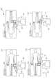
- FIG. 9 shows a selection screen 121 for selecting the type.
- the robot control device 80 displays a plurality of images 122 indicating different types A to D of the positional relationship between the patient P and the robot 20, and a selection button B21 for accepting the selection of the type, on the selection screen 121.
- the robot system 10 is capable of setting, for example, types A to D shown in FIG. 9 as posture types.
- Type A shown in the upper left of FIG. 9 is a posture type in which the robot 20 is placed on the left hand side of the patient P and the robot arm 21 is operated in a left arm posture.
- Type 9 is a posture type in which the robot 20 is placed on the right hand side of the patient P and the robot arm 21 is operated in a left arm posture.
- Type C shown in the lower left of FIG. 9 is a posture type in which the robot 20 is placed on the left hand side of the patient P and the robot arm 21 is operated in a right arm posture.
- Type D shown in the lower right of FIG. 9 is a posture type in which the robot 20 is placed on the right hand side of the patient P and the robot arm 21 is operated in a right-arm posture.
- the left-arm posture is, for example, a posture in which the second joint axis 32 is placed on the left side in the Y-axis direction relative to the first joint axis 31.
- the right-arm posture is, for example, a posture in which the second joint axis 32 is placed on the right side in the Y-axis direction relative to the first joint axis 31.
- the robot control device 80 displays the selection screen 121 of FIG. 9 on the operation panel 90 and accepts the selection of one type from four types (selection button B21). When one of the four selection buttons B21 is touched, the robot control device 80 sets the type corresponding to the touched selection button B21 as the selected type. The robot control device 80 acquires the posture type based on the selected type.
- FIG. 10 shows the relationship between types A to D and the sorting priority of each axis direction.
- the data shown in FIG. 10 is stored as setting data in the storage unit 85 of the robot control device 80.
- the robot control device 80 determines the sorting conditions for sorting the order (playback order) based on the selected type and this setting data.
- the robot system 10 of this embodiment is used, for example, as an ultrasonic echo guide for catheter surgery.
- the sorting priority is set according to the blood vessels that are the subject of the surgery. Specifically, the blood vessels in the thigh, which is the subject of surgery, run through the thigh from the groin to the toes, from the outside to the inside of the leg, and from the top to the bottom of the patient lying on his back.
- the sorting priority is set according to this type of surgical subject.
- the sorting priority is "Y-axis ascending", “X-axis ascending”, “Z-axis descending”, and “Registration ascending”.
- the robot control device 80 first sorts each point in ascending order in the Y-axis direction (order going from right to left in Figure 9) based on the Y coordinate value (see Figure 6). This makes it possible to automatically rearrange the order of the points so that they are lined up in the direction from the base of the patient P's foot to the toes, based on the relative positions of the robot 20 and the patient P.
- the robot control device 80 also sorts points with the same Y coordinate value so that they are arranged in ascending order in the X-axis direction (from bottom to top in FIG. 9) based on their X-coordinate value (see FIG. 6). This allows the order of points to be automatically rearranged so that they are arranged in a direction from the outside to the inside of the foot when the Y-coordinate value is the same.
- the robot control device 80 sorts the points in descending order in the Z-axis direction (from top to bottom, see FIG. 6) based on the Z coordinate value. This makes it possible to automatically rearrange the order of points that have the same X and Y coordinate values, for example, so that they are arranged in a top-to-bottom direction for patient P who is lying on his back.
- the robot control device 80 sorts points that have the same X, Y, and Z coordinate values in ascending order of registration. Therefore, points that have the same X, Y, and Z coordinate values are rearranged in the order in which they were first registered.
- the robot control device 80 rearranges the order of points (registered points and temporary points, described below) and sets routes according to the above-mentioned sorting priority at a specified cycle or in response to the operator's operation.
- the sorting priority is "Y-axis descending order", “X-axis ascending order”, “Z-axis descending order”, and "registration ascending order”. That is, the sorting order of the Y-axis, which has the highest priority, is reversed.
- the robot control device 80 first sorts the order of each point in descending order in the Y-axis direction (from left to right in FIG. 9) based on the Y coordinate value.
- the order can be automatically rearranged so that the points are arranged in the direction from the base of the patient P's foot to the toes based on the positional relationship between the robot 20 and the patient P.
- the X-axis, Z-axis, and registration order are the same as those of Types A and C described above, and therefore will not be described here.
- the sorting priority contents shown in FIG. 10 are merely examples.
- the priority of the X-axis may be higher than that of the Y-axis.
- the method of determining the priority is not limited to the method based on the user's selection described above.
- the robot control device 80 may detect the direction in which the patient P is sleeping by image recognition, and determine the type A to C based on the direction of the patient P's head and feet to set the priority order (sorting condition).
- the order subject to sorting in this disclosure is not limited to the order in which the points are played back, i.e., the order in which the echo images are acquired.
- the ultrasound device 100 is a device that performs treatment using the ultrasound probe 101, the order may be the order in which the treatment is performed.
- the robot control device 80 accepts the selection of any sorting condition from among the multiple different sorting conditions shown in FIG. 10 via the operation panel 90, and rearranges the order based on the selected sorting condition. This allows the operator to change the sorting conditions depending on the relative positions of the robot 20 and the patient P, etc. Sorting can be performed according to the usage environment.
- the robot control device 80 also displays multiple images 122 indicating the positional relationship between the patient P being treated by the ultrasound probe 101 and the robot 20, as well as selection buttons B21 on the operation panel 90, and rearranges the order based on sorting conditions according to the type of positional relationship indicated by the selected selection button B21. This allows the operator to visually confirm the positional relationship (type) from the images 122, and intuitively select appropriate sorting conditions. This reduces the burden of the work of selecting sorting conditions.
- the sorting conditions are set to sort by coordinates in each of the X, Y, and Z axis directions (an example of the first sorting condition and second sorting condition of the present disclosure).
- the robot control device 80 sorts the order by X-axis coordinate value according to the priority as described above, for example, when the Y coordinate value is the same. This makes it possible to set a priority for each axis and perform sorting. Depending on the purpose of use of the robot 20, the usage environment, the relationship with the target object (patient P), etc., a priority can be set for each axis direction and an appropriate sort can be performed.
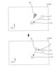
- FIG. 11 shows the registered point display section 131 of the operation panel 90, and shows the change in the state in which the points are registered. Note that the image 133 shown in FIG. 8 is omitted in the following FIGS. 11 to 16. Also, the robot control device 80 does not need to display the image 133 simulating a human body in the registration point display section 131.
- the operator registers the first registration point P1 at any position.
- the operator changes the position of the ultrasonic probe 101 while pressing the direct teaching switch 61.
- the robot control device 80 displays the current position of the ultrasonic probe 101 as the current position PA on the registration point display unit 131.
- the dashed arrow in the diagram is a schematic representation of the trajectory of movement of the ultrasonic probe 101 for ease of explanation, and is not actually displayed.
- the robot control device 80 may display the trajectory of movement of the ultrasonic probe 101, such as the dashed arrow.
- the operator registers the registration point P1 by stepping on the first switch 911 of the foot switch 91 at a predetermined position.
- the robot control device 80 stores information on the position and posture (X, Y, Z coordinate values and the angle values of Ra, Rb, Rc) of the ultrasonic probe 101 at the current position PA, and the position of each axis of the robot arm 21 (angle values and elevation coordinate values) in the memory unit 85 as information on the registration point P1 (an example of the storage process and storage step of the present disclosure).
- the robot control device 80 changes the display of the current position PA to the registration point P1, and displays the number "1" indicating that it is the first registration at the registration point P1.
- the robot control device 80 sorts the order of the already registered registration point P1 and the newly registered current position PA in ascending order in the Y-axis direction. As shown in the second figure from the bottom left of FIG. 11, the current position PA is on the positive side (left side) of the registered point P1 in the ascending order in the Y-axis direction.
- the robot control device 80 sets the order of the point of the current position PA to be second and registers it as the registered point P2 (see the bottom left figure). Then, the robot control device 80 sets the route L1 from the registered point P1 to the registered point P2 according to the sorting order.
- the robot control device 80 displays an arrow from the registered point P1 to the registered point P2, that is, an arrow indicating the sorting order (playback order), as an image of the route L1.
- the robot control device 80 sets the straight line connecting the registered point P1 and the registered point P2 in the XYZ coordinates, that is, the route with the shortest distance, as the route L1.
- the robot control device 80 moves the ultrasonic probe 101 along this path L1.
- the path L1 is not limited to the shortest distance connecting the registered points P1 and P2.
- the path L1 may be a curve with a predetermined curvature.
- the operator registers a third registration point P3.
- the robot control device 80 sets a route L2 from the registration point P2 to the registration point P3. In this way, each time a registration operation is performed, the robot control device 80 executes a sort including the newly registered point, and executes a route setting process to set a route according to the sort order.
- the registration points P1, P2, and P3 are registered in this order from right to left.
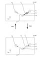
- the operator may return the ultrasound probe 101 to the entrance side where the catheter is inserted and register a new registration point (hereinafter, sometimes referred to as a new registration point).
- a new registration point hereinafter, sometimes referred to as a new registration point.
- the current position PA may be moved to the right of the registration point P2, that is, to the negative side in the Y-axis direction, and registered as a new registration point.
- the robot control device 80 sorts the already registered registration points P1 and P2 including the new registration point, and sets routes L1 and L2 between the new registration point and the registration points P1 and P2 adjacent to the new registration point according to the sorting order after rearrangement (an example of the first re-route setting process of the present disclosure).
- the robot control device 80 sets the current position PA as the registration point P2 and the already registered registration point P2 as the registration point P3 based on the sorting order.
- the robot control device 80 also sets a route L1 connecting the registered point P1 and the new registered point P2, and sets a route L2 connecting the new registered point P2 and the new registered point P3.
- a route setting process is performed between the newly registered point (current position PA) and the already registered registered points P1 and P2. This allows sorting to be performed each time a new registered point is registered, and appropriate routes L1 and L2 to be automatically set. If a registered point is registered by returning to an earlier point than a registered point, or by moving to a later point, rearrangement can be performed and the route can be re-set.
- the above-mentioned route setting process also occurs when the positions of the already registered registered points P1 to P3 are adjusted.
- the positions of the registered registered points P1 to P3 can be adjusted by the fine adjustment function or direct teaching described above. For example, the case where the position of the registered point P2 is adjusted after the three registered points P1 to P3, the second from the top right in FIG. 11, are registered (P1 ⁇ P2 ⁇ P3) will be described.
- the robot control device 80 periodically executes the route setting process and executes sorting. For example, the robot control device 80 maintains the direction of the arrow (the relationship of the connecting points) while updating the routes L1 and L2 until the position of the registered point P2 being adjusted becomes left of the position of the registered point P3 (the second diagram from the bottom right in FIG.
- the robot control device 80 executes rearrangement of the order and resetting of the routes L1 and L2.
- the sorting order changes from "P1 ⁇ P2 ⁇ P3" to "P1 ⁇ P3 ⁇ P2.” Therefore, the robot control device 80 changes the direction of the arrow of the path L2 connecting the pre-change registration point P3 (post-change registration point P2) and the pre-change registration point P2 (post-change registration point P3).
- the robot control device 80 also sets a new path L1 that goes from the registration point P1 to the post-change registration point P2 (pre-change registration point P3).
- the robot control device 80 executes sorting and sets routes L1, L2 connecting registered points P1 to P3 according to the order after rearrangement. This allows the route setting process to be executed even while the positions of registered points P1 to P3 are being adjusted, and when the order needs to be changed due to a change in position, the order and routes can be automatically updated. Note that, in the example shown in FIG.
- the robot control device 80 accepts a playback instruction operation based on the operation of the playback mode button B9 or the movement button B10 (see FIG. 8).
- the robot control device 80 accepts a playback instruction, it moves the ultrasonic probe 101 along the routes L1 and L2 in the order of the registered points P1 to P3.
- the robot control device 80 moves the ultrasonic probe 101 along the routes L1 and L2 in order from the registered point P1, and also changes the position of the displayed current position PA. In the state shown in the upper diagram of FIG.
- the current position PA moves along the route L1 from the registered point P1 toward the registered point P2.
- the robot control device 80 accepts an operation to return to a predetermined registered point or a front point along the route, it executes control to return the ultrasonic probe 101 (current position PA).
- the robot control device 80 when the robot control device 80 starts moving from the registered point P1, the arrow of the path L1 is changed to an arrow pointing in both directions, that is, to an arrow pointing not only to the registered point P2, which is the destination, but also to the registered point P1, which is the source of the movement. This makes it easy to see which registered point the robot returns to when it executes a return operation, as well as the destination of the movement.
- the robot control device 80 also makes the arrow pointing from the current position PA to the registered point P2 and the arrow pointing from the current position PA to the registered point P1 different colors and shapes. That is, the arrow pointing from the current position PA to the front point and the arrow pointing to the rear point are different arrows.
- the arrow pointing from the current position PA to the rear point (registered point P2), which is the destination of the movement, is made a thick red arrow (hereinafter referred to as a thick arrow), and the arrow pointing from the current position PA to the front point (registered point P1) is made a thin white arrow (hereinafter referred to as a thin arrow).
- a thick red arrow hereinafter referred to as a thick arrow
- a thin white arrow hereinafter referred to as a thin arrow
- the above-mentioned display method is an example and can be changed as appropriate.
- the arrow pointing from the current position PA to the front point and the arrow pointing to the rear point may be the same arrow.
- the arrow being played back does not have to be an arrow in both directions.
- the operator registers a new registration point in the middle of route L1.
- the robot control device 80 sorts the already registered registration points P1 to P3, including the new registration point, and sets a new registration point P2 at the current position PA as shown in the lower diagram of Figure 13, and sequentially moves the registered points P2 and P3 before registration down to registered points P3 and P4.
- the robot control device 80 also sets a new route L1 connecting registered point P1 and registered point P2, and a new route L2 connecting registered point P2 and registered point P3, and moves route L2 connecting registered points P3 and P4 down to route L3. This allows the operator to register a new registration point in the middle of route L1 and reset the sort order and route.
- the robot control device 80 also executes the route setting process when any registered point is deleted. For example, in the state shown in the lower diagram of FIG. 13, when an operation to delete registered point P2 is received, the robot control device 80 sets route L1 connecting registered point P3, which is the rear point, and registered point P1, which is the front point, and increments the point numbers and route numbers from registered point P3 onwards. This results in the state shown in the upper diagram of FIG. 13.
- the ultrasonic probe 101 is stopped in the middle of the path L1 shown in the upper diagram of FIG. 13, and the position of the current position PA (ultrasonic probe 101) deviates from the path L1 as shown in the upper left diagram of FIG. 14.
- the ultrasonic probe 101 deviates from the path L1 and moves to a position shifted in the positive direction of the X coordinate and the positive direction of the Y coordinate.
- the robot control device 80 rearranges the order based on the sorting conditions, including the current position PA of the ultrasonic probe 101 after the movement, in addition to the already registered registration points P1 to P3.
- the robot control device 80 sets a path between the current position PA and the registration points P1 and P2 adjacent to the current position PA according to the rearranged sorting order (an example of the first re-route setting process of the present disclosure).
- the robot control device 80 moves the current position PA in accordance with the movement of the ultrasonic probe 101, sets a new path L1 from the current position PA to the registered point P1, and a new path L2 from the current position PA to the registered point P2, and moves the path L2 between the registered points P2 and P3 to a path L3.
- the robot control device 80 also displays a thin arrow pointing to the front point and a thick arrow pointing to the rear point as shown in the upper diagram of FIG. 13 as the arrows of the paths L1 and L2. This makes it possible to set new paths L1 and L2 when the ultrasonic probe 101 is moved to a position deviating from the already set path L1.
- the paths L1 and L2 are made to follow the current position PA in accordance with the movement of the ultrasonic probe 101, and the paths L1 and L2 can be changed so as to connect the current position PA to each of the front and rear points.
- the robot control device 80 executes a route setting process including the current position PA.
- the robot control device 80 stores information on the position and orientation of the ultrasound probe 101 at the current position PA and the positions of each axis of the robot arm 21 in the memory unit 85 as information on a new registration point P2.
- the robot control device 80 sets the current position PA as the new registration point P2, and lowers the numbers of the registration points after the new registration point P2.
- the diagram at the bottom left of FIG. 14 shows a state in which the current position PA in the diagram at the top left has been changed, and then playback has been performed from the changed current position PA toward the rear point, i.e., the movement of the ultrasonic probe 101 has been performed.
- the ultrasonic probe 101 moves along the path L2 toward the registered point P2.
- the robot control device 80 sets the position before the movement as a temporary point PB, and displays it differently from the current position PA (displayed in a different color or shape).
- the temporary point PB is the point after the position has been changed as described above, and is a temporary point that becomes the starting point after the change.
- the temporary point PB is also a point to which the operator has moved the ultrasonic probe 101, deviating from the set paths L1 and L2, and is a point to which the operation of registering it as a registered point has not been performed.
- the robot control device 80 When the ultrasonic probe 101 (current position PA) starts moving from the temporary point PB, the robot control device 80 maintains the arrow from the current position PA pointing to the registered point P2 as a thick arrow, while changing the arrow from the current position PA pointing to the temporary point PB to a thin arrow. The robot control device 80 also maintains the arrow from the temporary point PB pointing to the registered point P1 as a thin arrow. Therefore, the robot control device 80 displays the arrows before and after the current position PA while moving from the temporary point PB to the rear point in the same way as when moving along the set route described above, while maintaining the arrow from the temporary point PB pointing to the front point as a thin arrow.
- the robot control device 80 also executes a similar display process when the ultrasonic probe 101 moves from the temporary point PB to the front point (registered point P1). That is, the robot control device 80 maintains the arrow on the path L1 pointing from the current position PA to the registered point P1 as a thin arrow, while changing the arrow from the current position PA to the temporary point PB to a thick arrow. Also, the robot control device 80 maintains the arrow pointing from the temporary point PB to the registered point P2 as a thick arrow.
- the robot control device 80 executes a route setting process including the current position PA on the route L2.
- the sorting of this route setting process does not include the temporary point PB.
- the robot control device 80 erases the display of the temporary point PB in response to a point registration operation, and also deletes the data related to the temporary point PB.
- the robot control device 80 executes a sorting process including the current position PA to the already registered registration points P1 to P3.
- the robot control device 80 sets the current position PA as the second registered point P2, and moves the numbers of the subsequent registered points down to 3 and 4.
- the robot control device 80 sets routes L1 and L2 between the new registered point P2 (current position PA) and the adjacent registered points (registered point P1, registered point P3 after the move).
- route L3 is maintained as route L3. This allows the operator to check the echo image while moving from the temporary point PB, and if a newly registered point is found, it can be registered as a new registered point. Also, the operator can delete the temporary point PB, lower the number, and set new routes L1 and L2 simply by performing the registration operation.
- FIG. 15 shows a case in which the current position PA is further changed from the state shown in the upper left diagram of FIG. 14 (the state in the upper left diagram of FIG. 15) and moved to the positive side of the Y coordinate (later in the sorting order) of registered point P2, which is a rear point (lower in the sorting order) (lower left diagram of FIG. 15).
- the robot control device 80 executes the route setting process at a predetermined cycle, and when the current position PA moves to a position to the left of the registered point P2, it updates the route connecting the current position PA and the other registered points.
- the sorting order changes from "P1 ⁇ PA ⁇ P2 ⁇ P3" to "P1 ⁇ P2 ⁇ PA ⁇ P3". Therefore, as shown in the lower left diagram of FIG. 15, the robot control device 80 erases the thick arrow from the current position PA to the registered point P2, sets a new route L3 from the current position PA to the registered point P3 (rear point), and displays the route L3 with a thick arrow.
- the robot control device 80 erases the thin arrow from the current position PA to the registered point P1, sets a new route L2 from the current position PA to the registered point P2 (front point), and displays the route L2 with a thin arrow. In this way, if the positional relationship (sorting order) between the current position PA and the other registered points P1 to P3 changes during the adjustment of the current position PA, the robot control device 80 executes route resetting.
- the robot control device 80 rearranges the order of the current position PA and the rear point based on the sorting conditions.
- the robot control device 80 sets a path L2 between the current position PA and the rear point (registered point P2) according to the rearranged order.
- the robot control device 80 registers the points according to the sorting order. In this case, the robot control device 80 makes the current position PA the third registered point P3, and moves the original registered point P3 down to registered point P4.
- the path setting process is performed when the operator intentionally changes the position.
- the path setting process may also be performed when other positions are changed.
- the robot 20 of this embodiment performs an evacuation operation using the force sensor 68 of the third rotation device 57.
- the robot control device 80 acquires the external force applied from the patient P to the hand part 60, in other words, the pushing force of the ultrasonic probe 101 against the body surface of the patient P, based on the detection signal of the force sensor 68.
- the robot control device 80 displays the acquired external force on the operation panel 90, etc., and determines whether the external force is equal to or greater than a predetermined reference value.
- This predetermined reference value is, for example, a value for judging the external force applied from the patient P to the hand part 60, and is the upper limit of the pushing force allowed when pushing the ultrasonic probe 101 into the body surface of the patient P.
- the reference value can be set in advance by experiment, for example, as a force that does not cause the patient P to feel pain or discomfort. If the robot control device 80 determines that the external force is less than the reference value, it continues the operation (diagnosis, etc.). On the other hand, if the robot control device 80 determines that the external force is equal to or greater than the reference value, it moves the ultrasonic probe 101 upward a predetermined distance and stops it (emergency stop), for example. Then, the robot control device 80 displays a warning on the operation panel 90, etc. Note that the direction of retraction is not limited to upward, and other directions that move the ultrasonic probe 101 away from the patient P can be used.
- the current position PA changes during this retraction operation.
- the coordinate that changes is basically only the Z coordinate.
- the X coordinate value and the Y coordinate value change.
- a retraction operation may occur midway through the path L1, causing the current position PA to deviate from the path L1.
- a retraction operation may occur during adjustment of the position of the registered point P2, causing the registered point P2 to retract (move) to the left of the registered point P3.
- a retraction operation may occur after deviating from the path, causing the current position PA to retract (move) to the left of the registered point P2.
- the above-mentioned route setting process is executed even during such a retraction operation. This allows automatic order sorting and route setting to be executed even during the retraction operation.
- the robot controller 80 moves to a front or rear point without registering a new registered point or changing the current position PA.
- the ultrasonic probe 101 is moved to a position deviated from the path L1, and then the registered point is regenerated to move the ultrasonic probe 101, and the current position PA moves.
- the robot controller 80 sets the position before the movement as the temporary point PB. Then, as shown in the upper right diagram of FIG.
- the robot controller 80 erases the display of the temporary point PB and the paths L1 and L2, and also deletes the data related to the temporary point PB.
- the robot controller 80 newly sets the path between the registered points P1 and P2, i.e., the path between the rear and front points before reaching the registered point P2, as the path L1.
- the robot control device 80 deletes the current position PA and routes L1 and L2 and sets a new route L1.
- the robot control device 80 also advances route L3 to route L2.
- the temporary point PB can be erased by moving the ultrasonic probe 101 to the front or rear point.
- the temporary point PB can be erased simply by moving the ultrasonic probe 101 to the previous or next registered point.
- the robot control device 80 executes a path setting process (a second re-route setting process of the present disclosure). Specifically, as shown in the lower right diagram of FIG. 16, when the ultrasonic probe 101 is moved to a position deviating from the path L2 while moving from the temporary point PB to the registered point P2 of the rear point, the robot control device 80 erases the display of the temporary point PB and also deletes the data related to the temporary point PB.
- the robot control device 80 executes sorting of the multiple registered points P1 to P3 stored in the storage unit 85, including the current position PA after the movement, and sets new paths L1, L2 connecting the current position PA and each of the front and rear points according to the sorting order after the rearrangement. This allows the confirmation of the echo image of the position deviating from the path L2 while checking the echo image, and the registration of that position.
- the temporary point PB can be deleted simply by changing the position, which reduces the workload of the operator.
- the robot control device 80 deletes the temporary point PB and resets the paths L1 and L2 in the same manner as the path L2 described above.
- the ultrasound probe 101 of this embodiment is an example of a probe of the present disclosure.
- the robot arm 21 is an example of an arm.
- the force sensor 68 is an example of an external force acquisition device.
- the robot control device 80 is an example of a control device.
- the memory unit 85 is an example of a memory unit.
- the operation panel 90 and the tablet terminal 93 are examples of a user interface and a display device.
- the ESR controller 92, the foot switch 91, and the emergency stop switch 94 are examples of a user interface.
- the patient P is an example of an object to be photographed.
- the X, Y, and Z axis directions are examples of a first axis direction and a second axis direction.
- the robot control device 80 which is one aspect of this embodiment, rearranges the order of the multiple registered points P1 to P3 stored in the storage unit 85 based on a sorting condition according to the selected type, and sets paths L1 to L3 along which the ultrasonic probe 101 moves between the points according to the rearranged order. This reduces the operator's workload of adjusting the registered points P1 to P3 that have already been registered and the registered point to be newly registered.
- the present disclosure is not limited to the above-described embodiments, and it goes without saying that various improvements and modifications are possible without departing from the spirit and scope of the present disclosure.
- the configuration of the robot system 10 in the above embodiment is just an example.
- the ESR controller 92 may be connected to the robot 20 by a wire.
- the storage unit 85 that stores the registration points P1 to P4 may be a device separate from the robot system 10, for example, a cloud storage on a network.
- the robot 20 is configured as a seven-axis articulated robot capable of translational motion in three directions and rotational motion in three directions.
- the number of axes may be any number.
- the robot 20 may be configured as a so-called vertical articulated robot, horizontal articulated robot, or the like.
- the X-axis, Y-axis, and Z-axis directions are perpendicular to each other as the first and second axis directions of the present disclosure, but this is not limited to this.
- the angle between the X-axis direction and the Y-axis direction is not limited to 90 degrees, and may be other angles. Therefore, the angle at which the first and second axis directions of the present disclosure intersect is not limited to 90 degrees.
- the robot 20 has a plurality of sorting conditions (see FIG. 10) in accordance with types A to D, it may be configured to have only one sorting condition.
- the ultrasound device of the present disclosure is not limited to a device that captures an echo image, but may be a device that captures an echo image and performs treatment, such as high intensity focused ultrasound therapy (HIFU), etc. In other words, the purpose of use of the ultrasound emitted from the probe can be changed as appropriate.
- HIFU high intensity focused ultrasound therapy
Landscapes
- Engineering & Computer Science (AREA)
- Robotics (AREA)
- Mechanical Engineering (AREA)
- Ultra Sonic Daignosis Equipment (AREA)
Abstract
プローブを移動させる位置を登録する負担を軽減できるロボット、及び経路設定方法を提供すること。 ロボットは、超音波装置のプローブを保持可能なアームと、アームの動作を制御する制御装置と、を備える。制御装置は、操作者の操作に応じてプローブの位置を変更し、変更後のプローブの位置を登録ポイントとして記憶装置に記憶する記憶処理と、記憶処理により記憶装置に記憶した複数の登録ポイントの順番を、登録ポイントの順番を並び替えるソート条件に基づいて並び替え、並び替えた後の順番に従って複数の登録ポイントの間でプローブを移動させる経路を設定する経路設定処理と、を実行する。
Description
本開示は、ロボット、及び経路設定方法に関するものである。
従来、この種のロボットとしては、超音波プローブを保持して被検体の体表面に沿って超音波プローブを移動させるロボットアームと、ロボットアームによって超音波プローブを移動させるための指示軌跡情報を記憶する記憶部と、記憶された指示軌跡情報に従って超音波プローブを移動させるようにロボットアームの駆動を制御するロボットアーム制御部と、を備えるものが提案されている(例えば、特許文献1参照)。
上記したロボットでは、記憶部に記憶した指示軌跡情報に従ってロボットアームを制御し超音波プローブを移動させている。指示軌跡情報を登録している際や、指示軌跡情報に従って超音波プローブを移動させ施術を行っている際に、超音波プローブを移動させる位置に変更が生じた場合、操作者は、既に登録したポイントと、新たに登録するポイントとの調整を行わなければならない虞がある。その結果、操作者の作業負担が増加する問題があった。
本開示は、上記の課題に鑑みてなされたものであり、プローブを移動させる位置を登録する負担を軽減できるロボット、及び経路設定方法を提供することを目的とする。
上記課題を解決するために、本明細書は、超音波装置のプローブを保持可能なアームと、前記アームの動作を制御する制御装置と、を備えるロボットであって、前記制御装置は、操作者の操作に応じて前記プローブの位置を変更し、変更後の前記プローブの位置を登録ポイントとして記憶装置に記憶する記憶処理と、前記記憶処理により前記記憶装置に記憶した複数の前記登録ポイントの順番を、前記登録ポイントの順番を並び替えるソート条件に基づいて並び替え、並び替えた後の順番に従って複数の前記登録ポイントの間で前記プローブを移動させる経路を設定する経路設定処理と、を実行する、ロボットを開示する。
本開示のロボット、経路設定方法によれば、ソート条件に基づく登録ポイントの順番の並び替えを実行し、登録ポイント間を結ぶ経路を設定する。これにより、操作者が、登録済みの登録ポイントと、新たに登録する登録ポイントとの調整をする作業負担を軽減できる。プローブを移動させる位置を登録ポイントとして登録する負担を軽減できる。
以下、本開示のロボットを具体化した一実施形態について図面を参照しながら説明する。図1は、本実施形態のロボットシステム10の外観斜視図である。図2は、ロボット20の概略構成図である。図3及び図4は、手先部60を含むロボット20の部分拡大図である。図5は、ロボットシステム10の電気的な接続関係を示すブロック図である。尚、以下の説明では、図1及び図2に示すように、ロボット20の操作パネル90を操作する操作者から見た方向を基準として、前後方向をX軸方向、左右方向をY軸方向、上下方向をZ軸方向と称して説明する。
本実施形態のロボットシステム10は、図1~図5に示すように、多関節のロボットアーム21を有するロボット20と、フットスイッチ91と、ESRコントローラ92と、タブレット端末93と、非常停止スイッチ94と、を備える。ロボットシステム10は、図1~図4に示すように、ロボットアーム21の手先に超音波装置100の超音波プローブ101を保持し、超音波プローブ101を人体の体表面に押し当てて移動するようにロボット20を制御することにより、超音波装置100に人体の超音波エコー画像を取得させる。ロボットシステム10は、例えばカテーテル手術などの手術時の超音波エコーガイドとして用いられる。カテーテルのガイドワイヤを操作する操作者(術者)は、ロボット20に指示して超音波プローブ101を人体(患者)の体表面に押し当て、得られる超音波エコー画像からガイドワイヤの先端と血管との位置関係を認識しながら、ガイドワイヤを進めることで、ガイドワイヤを正確に血管の閉塞部位や狭窄部位の中央を通すことができる。
操作者は、事前準備として、ロボットアーム21を手動操作し、ロボットアーム21に保持された超音波プローブ101を患者に当てて取得される超音波エコー画像を確認しつつ、手術中に再現したいポイント(画像)を決定してロボット20(ロボット制御装置80)に登録するダイレクトティーチングを行なう。
超音波装置100は、図1に示すように、超音波プローブ101と、超音波プローブ101とケーブル102を介して接続された超音波装置本体110と、を備える。超音波装置本体110は、図5に示すように、装置全体の制御を司る超音波診断制御部111と、超音波プローブ101からの受信信号を処理して超音波エコー画像を生成する画像処理部112と、超音波エコー画像を表示する画像表示部113と、各種操作スイッチ(図示せず)と、を備える。尚、超音波プローブ101としては、1次元のリニア型、コンベックス型の他、2次元や3次元の多次元のプローブ、H型などの他形状のプローブも採用できる。
図1及び図2に示すように、ロボット20は、基台25と、基台25上に設置された筐体29と、筐体29に支持されたロボットアーム21と、ロボットアーム21の先端部に取り付けられた手先部60と、ロボットアーム21を制御するロボット制御装置80と、操作パネル90と、を備えている。
基台25の裏面の四隅には、ストッパ付きのキャスター26が取り付けられている。ロボット20は、キャスター26により自由に移動させることが可能である。また、基台25の裏面の複数箇所(例えば3箇所)には、レバー27を押し下げることにより鉛直下方向に突出してロボット20を移動不能にロック(固定)するロック部28が設けられている。
ロボットアーム21は、本実施形態では、例えば、7軸の多関節アームであり、第1アーム22と第2アーム23とベース24と第1アーム駆動装置35と第2アーム駆動装置36と姿勢保持装置37と回転3軸機構50とブレーキレバー65(図4参照)とを有する。
第1アーム22の基端部は、上下方向(Z軸方向)に延在する第1関節軸31を介してベース24に連結されている。第1アーム駆動装置35は、モータ35aとエンコーダ35bとアンプ35cとを備える(図5参照)。モータ35aの回転軸は、図示しない減速機を介して第1関節軸31に接続されている。第1アーム駆動装置35は、モータ35aにより第1関節軸31を回転駆動することにより、第1関節軸31を支点に第1アーム22を水平面(XY平面)に沿って回動(旋回)させる。エンコーダ35bは、モータ35aの回転軸に取り付けられ、モータ35aの回転変位量を検出するロータリエンコーダとして構成される。アンプ35cは、スイッチング素子のスイッチングによりモータ35aを駆動するための駆動部である。
第2アーム23の基端部は、上下方向に延在する第2関節軸32を介して第1アーム22の先端部に連結されている。第2アーム駆動装置36は、モータ36aとエンコーダ36bとアンプ36cとを備える(図5参照)。モータ36aの回転軸は、図示しない減速機を介して第2関節軸32に接続されている。第2アーム駆動装置36は、モータ36aにより第2関節軸32を回転駆動することにより、第2関節軸32を支点に第2アーム23を水平面に沿って回動(旋回)させる。エンコーダ36bは、モータ36aの回転軸に取り付けられ、モータ36aの回転変位量を検出するロータリエンコーダとして構成される。アンプ36cは、スイッチング素子のスイッチングによりモータ36aを駆動するための駆動部である。
本実施形態では、第1アーム22と第2アーム23は、水平関節アームを構成する。このため、ロボット20は、腕姿勢として、ロボットアーム21を右腕姿勢で動作させる右腕姿勢モードと、ロボットアーム21を左腕姿勢で動作させる左腕姿勢モードと、を有する。
図2に示すように、筐体29内には、昇降装置40が設けられている。昇降装置40は、基台25の上に設置されている。ベース24は、ロボットアーム21の基端部に設けられ、昇降装置40により、基台25に対して昇降可能に設けられている。昇降装置40は、第1スライダ41と、第1ガイド部材42と、第1ボールねじ軸43(昇降軸)と、モータ44aと、エンコーダ44bと、アンプ44cと、を備える(図5参照)。第1スライダ41は、ベース24に固定されている。第1ガイド部材42は、上下方向に延出して第1スライダ41の移動をガイドする。第1ボールねじ軸43は、上下方向に延出すると共に第1スライダ41に固定されたボールねじナット(図示せず)に螺合されている。モータ44aは、第1ボールねじ軸43を回転駆動する。アンプ44cは、モータ44aを駆動する。昇降装置40は、モータ44aにより第1ボールねじ軸43を回転駆動することにより、第1スライダ41に固定されたベース24を第1ガイド部材42に沿って上下に移動させる。エンコーダ44bは、第1スライダ41(ベース24)の上下方向における位置(昇降位置)を検出するリニアエンコーダとして構成される。
回転3軸機構50は、図1、図2に示すように、上下方向に延在する姿勢保持用軸33を介して第2アーム23の先端部に連結されている。回転3軸機構50は、互いに直交する第1回転軸51,第2回転軸52及び第3回転軸53と、第1回転軸51を回転させる第1回転装置55と、第2回転軸52を回転させる第2回転装置56と、第3回転軸53を回転させる第3回転装置57と、を備える。第1回転軸51は、姿勢保持用軸33に対して直交する姿勢で支持されている。第2回転軸52は、第1回転軸51に対して直交する姿勢で支持されている。第3回転軸53は、第2回転軸52に対して直交する姿勢で支持されている。第1回転装置55は、第1回転軸51を回転駆動するモータ55aと、モータ55aの回転軸に取り付けられモータ55aの回転変位量を検出するエンコーダ55bと、モータ55aを駆動するアンプ55cと、を有する(図5参照)。第2回転装置56は、第2回転軸52を回転駆動するモータ56aと、モータ56aの回転軸に取り付けられモータ56aの回転変位量を検出するエンコーダ56bと、モータ56aを駆動するアンプ56cと、を有する(図5参照)。第3回転装置57は、第3回転軸53を回転駆動するモータ57aと、モータ57aの回転軸に取り付けられモータ57aの回転変位量を検出するエンコーダ57bと、モータ57aを駆動するアンプ57cと、を有する(図5参照)。
第3回転装置57は、第2回転軸52が連結されると共に第2回転軸52に対して直交方向に延出するように第3回転軸53を回転可能に支持する筐体54や、第3回転軸53を回転駆動するモータ57a、力覚センサ68等を備える(図5参照)。図3に示すように、筐体54は、それぞれ周方向(外周に沿った方向)につながる第1面54b、第2面54t、第3面54r及び第4面54fを有する箱形の部材である。第2回転軸52は、第3面54rに連結される。第3回転軸53は、第3面54rに対して直交する第1面54bから外方へ延出するように筐体54に対して回転可能に支持され、モータ57aにより回転駆動される。ここで、ロボットアーム21が後述する原点位置に位置した状態(図2に示す状態)において、第1面54bは下面となり、第2面54tは上面となり、第3面54rは背面となり、第4面54fは前面となる。筐体54の第2面54t(上面)には、図3に示すように、ダイレクトティーチングにおいて、ロボットアーム21に保持された超音波プローブ101を操作者が手動操作する際に、操作者により把持される操作ハンドル66や、ロボットアーム21に予期しない動作が発生した際に操作者の操作によりロボットアーム21の動作を一時的に停止させるための停止スイッチ67が配置される。
力覚センサ68は、筐体54内に設けられ、第3回転軸53に取り付けられる。力覚センサ68は、筐体54内に設けられたモータ57aからの動力を第3回転軸53(手先部60)に伝達すると共に、手先部60や操作ハンドル66に加わる外力としてX軸,Y軸及びZ軸の各軸方向に作用する力成分とRa,Rb及びRcの各軸周りに作用するトルク成分とを検出する。
手先部60は、第3回転軸53の先端部に取り付けられる。手先部60は、基部601と、第3回転軸53と同軸になるように超音波プローブ101を保持する保持部602と、操作者により把持される部分である把持部603と、を有する。基部601は、プレート状の部材であり、パッチン錠64により第3回転軸53に対して着脱可能に取り付けられている。尚、手先部60(基部601)は、他の固定具(例えば、ラチェット式固定具や、ねじ等)により第3回転軸53に取り付けられても良い。
保持部602は、基部601の一方の表面に設けられ、超音波プローブ101を保持する。保持部602は、例えば、超音波プローブ101を両サイドから支持する一対の支持壁と、一方の支持壁から他方の支持壁に架け渡され超音波プローブ101を基部601に押さえ付けて保持する板状の押さえ部材と、を備えている。この押さえ部材は、一辺側が一方の支持壁にヒンジを介して回動可能に取り付けられると共に、反対側の他辺側が他方の支持壁に固定具(例えば、パッチン錠)により係脱可能に固定される。従って、押さえ部材は、一対の支持壁に対して開閉可能となっており、超音波プローブ101を保持する閉状態と、超音波プローブ101を着脱可能な開状態とに切り替わる。これにより、保持部602は、例えば、リニア型の超音波プローブ101の表裏の向きを変えて、どちらの向きにしても取り付け可能となっている。
把持部603は、例えば、ダイレクトティーチングにおいて、ロボットアーム21に保持された超音波プローブ101を操作者が手で動かす際に、当該操作者により把持される。把持部603は、基部601の保持部602が設けられた一方の表面とは反対側の他方の表面に設けられ、当該他方の表面から外側に凸状に突出するように形成されている。本実施形態では、把持部603は、図3,図4に示すように、凸曲面により形成されるが、操作者が把持可能な形状であれば、例えばテーパー形状、棒状、半球状、直方体状、立方体状など如何なる形状により形成されても良い。また、把持部603における凸状部(凸曲面部)の頂部には、ダイレクトティーチングにおいて操作者によるロボットアーム21の手動操作を許可するためのダイレクトティーチングスイッチ61が設けられている。尚、ダイレクトティーチングスイッチ61を設ける位置は、適宜変更しても良い。
ダイレクトティーチングスイッチ61は、本実施形態では、3ポジションのイネーブルスイッチとして構成される。ダイレクトティーチングスイッチ61の端子には、ケーブル62の一端が接続される。手先部60の基部601における上記他方の表面であって把持部603よりも筐体54側には、ケーブル62の一端をダイレクトティーチングスイッチ61に導くケーブルガイド63が固定されている。ケーブル62の他端は、筐体54からロボットアーム21に沿ってロボット制御装置80につながる配線と接続される。本実施形態では、ケーブル62の他端には、コネクタ621が設けられており、筐体54に設けられたコネクタに対して抜き差し可能に接続される。このため、パッチン錠64を解錠すると共にコネクタ621を引き抜くことで、筐体54から手先部60を容易に切り離すことができ、メンテナンス性を向上させることができる。
本実施形態のロボット20は、第1アーム駆動装置35と第2アーム駆動装置36と昇降装置40とによるX軸方向、Y軸方向及びZ軸方向の3方向の並進運動と、回転3軸機構50によるX軸回りRb(ピッチング)、Y軸回り(ローリング)Ra及びZ軸回り(ヨーイング)Rcの3方向の回転運動との組み合わせにより、ロボットアーム21を動作させる。これにより、ロボット20は、図6に示すように、超音波プローブ101をX軸,Y軸及びZ軸の各軸方向(正逆両方向)に移動させると共にRa,Rb及びRcの各軸周り(正逆両回転方向)に回転させることができる。本実施形態では、X軸方向は、筐体29から超音波プローブ101を離す又は筐体29へ超音波プローブ101を近づける方向となっている。例えば、図6に示すように、X軸方向において、筐体29から超音波プローブ101を離す方向をプラス方向、筐体29へ超音波プローブ101を近づける方向をマイナス方向とする。また、Y軸方向において、左方向をプラス方向、右方向をマイナス方向とする。また、Z軸方向において、上方向をプラス方向、下方向をマイナス方向とする。尚、図6に示す方向及びプラス/マイナスの定義は一例である。また、本実施形態のロボットシステム10は、保持部602に保持された超音波プローブ101の先端における中央123(図6参照)を回転中心として保持部602を回転させるように、回転中心が設定されている。
姿勢保持装置37は、第1アーム22及び第2アーム23の姿勢によらず回転3軸機構50の姿勢(第1回転軸51の向き)を一定の向きに保持するものである。姿勢保持装置37は、モータ37aとエンコーダ37bとアンプ37cとを備える(図5参照)。モータ37aの回転軸は、図示しない減速機を介して姿勢保持用軸33に接続されている。姿勢保持装置37は、第1回転軸51の軸方向が常時、左右方向(Y軸方向)となるように第1関節軸31の回転角度と第2関節軸32の回転角度とに基づいて姿勢保持用軸33の目標回転角度を設定し、姿勢保持用軸33が目標回転角度となるようにモータ37aを駆動制御する。これにより、3方向の並進運動の制御と3方向の回転運動の制御とをそれぞれ独立して行なうことが可能となり、制御が容易となる。
ブレーキレバー65は、図4に示すように、回転3軸機構50(第1回転軸51)から図中、下方向(姿勢保持用軸33の延在方向)に延出すると共に延出端において直交方向に屈曲する略L字状の部材である。ロボットアーム21には、水平旋回する軸(第1関節軸31,第2関節軸32及び姿勢保持用軸33)を除いた各軸に対して機械ブレーキ(例えば、ディスクブレーキ)が取り付けられており、当該機械ブレーキは、対応するモータの動作の停止により作動するように構成されている。操作者は、ブレーキレバー65を図中、上方向に操作することで、機械ブレーキの作動を解除することができる。これにより、ロボット20の何らかの異常により電源が遮断されても、操作者は、機械ブレーキを手動により解除することができ、ロボットアーム21を動かして安全な位置に退避させることが可能となる。
操作パネル90は、ロボットシステム10に関する各種情報を表示すると共にロボットシステム10に対する各種指示を入力可能なタッチパネル式のディスプレイである。操作パネル90は、本実施形態では、ロボット20の昇降装置40やロボット制御装置80が収容された筐体29の上面に設置されている。
図1に示すフットスイッチ91は、操作者による踏み込みによってオンするペダルスイッチであり、ケーブルを介してロボット20のロボット制御装置80に接続される。本実施形態では、フットスイッチ91は、横方向に並ぶ4つのスイッチ(第1スイッチ911,第2スイッチ912,第3スイッチ913及び第4スイッチ914)を有する。
ESRコントローラ92は、操作者により両手で把持した状態で押下操作される操作コントローラであり、無線によりロボット20のロボット制御装置80に接続される。尚、ESRコントローラ92は、有線によりロボット20のロボット制御装置80に接続されても良い。ESRコントローラ92は、本実施形態では、図1に示すように、方向キーボタン921と、押しボタン922と、ボタン923と、ボタン924と、押しボタン925,926と、を有する。方向キーボタン921は、左手親指により操作可能なボタン(上ボタン、下ボタン、左ボタン及び右ボタン)を有する。押しボタン922は、右手親指により操作可能で且つひし形に配置された4つのボタン(Aボタン、Bボタン、Xボタン及びYボタン)を有する。ボタン923は、それぞれ左手人差し指、左手中指により操作可能なL1ボタン、L2ボタンを有する。ボタン924は、それぞれ右手人差し指、右手中指により操作可能なR1ボタン、R2ボタンを有する。押しボタン925,926は、方向キーボタン921と4つの押しボタン922との間に複数配置されている。
タブレット端末93は、CPUやROM,RAM,ストレージ(SSD)を含む制御装置と、各種情報を表示すると共に操作者による入力操作が可能なタッチパネル式のディスプレイと、通信部と、を備える。タブレット端末93は、無線通信によりロボット20のロボット制御装置80と通信可能に接続される。本実施形態では、タブレット端末93は、操作パネル90を無線通信によって当該タブレット端末93から遠隔操作することができるリモートディスクトップ機能を有する。
非常停止スイッチ94は、非常時にロボット20を強制的に停止させるボタンであり、ケーブルを介してロボット制御装置80に接続されている。尚、非常停止スイッチ94は、ロボットアーム21、筐体29等に設けられても良い。
図5に示すように、ロボット制御装置80は、ロボット制御部81と監視部82とIO部83と通信部84と記憶部85とを備える。ロボット制御部81は、CPUやROM,RAM、周辺回路などを含むプロセッサとして構成されるものである。監視部82は、CPUやROM,RAM、周辺回路などを含むワンチップマイクロコンピュータとして構成されるものである。ロボット制御部81は、ロボットアーム21(モータ35a~37a,44a,55a~57a)の制御に係る各種処理を行なう。監視部82は、IO部83や、通信部84、アンプ35c~37c,44c,55c~57c、エンコーダ35b~37b,44b,55b~57b、ダイレクトティーチングスイッチ61等を含むセンサ部といった各部の状態を監視する。ロボット制御部81は、監視部82の監視結果に基づいて、ロボットシステム10の異常を検出する。IO部83は、I/Oポートであり、ダイレクトティーチングスイッチ61からの検出信号や停止スイッチ67からの検出信号、操作パネル90からの操作信号等を入力し、操作パネル90への表示信号等を出力する。通信部84は、有線又は無線によりロボット制御装置80と外部機器(フットスイッチ91やESRコントローラ92、タブレット端末93、非常停止スイッチ94等)との通信を行ない、各種信号やデータのやり取りを行なう。記憶部85は、例えば、RAM、ROM、HDD、SDDなどの記憶装置である。
アンプ35c~37c,44c,55c~57cには、それぞれ、モータ制御部71と駆動電力供給部72とIO部73とが含まれる。駆動電力供給部72は、例えば、モータ35a~37a,44a,55a~57aの駆動に必要な電力を供給するインバータ回路を備えている。モータ制御部71は、例えば、駆動電力供給部72のインバータ回路のスイッチング素子を、エンコーダ35b~37b,44b,55b~57b等からのエンコーダ情報に基づいてフィードバック制御(スイッチング制御)することで各モータ35a~37a,44a,55a~57aを制御する。IO部83は、I/Oポートであり、エンコーダ35b~37b,44b,55b~57bからのエンコーダ情報や各モータ35a~37a,44a,55a~57aを流れる電流を検知する電流センサからの電流信号、ロボット制御部81から各モータ35a~37a,44a,55a~57aへの指令信号(制御信号)等の各種信号を入力する。
ロボット20は、ロボットステータスとして、制御オフと制御オンとロボットオンとを有する。制御オフは、ロボット制御部81がロボットアーム21(モータ)を制御不能にアンプ35c~37c,44c,55c~57cへの電源供給を停止した状態である。制御オンは、ロボット制御部81がロボットアーム21を制御可能にアンプ35c~37c,44c,55c~57cへ電源供給している状態である。この状態では、ロボットアーム21を直接触ってその姿勢を変えることが可能である。ロボットオンは、制御オン状態からロボット制御部81がアンプ35c~37c,44c,55c~57cに制御信号を出力してロボットアーム21を制御している状態である。ロボットステータスは、作業者の指示に基づいて変更されると共に、監視部82の監視結果に基づいて変更される。
次に、こうして構成されたロボットシステム10が備えるロボット20のモードについて説明する。図7は、ロボット20の電源オンから電源オフまでに遷移するモードを説明する説明図である。ロボット20のロボット制御装置80は、電源オンが指示されると、まず、本システムを使用するための準備を行なう起動モードを実行する。
起動モードでは、利用前点検やユーザ選択・ユーザ設定、自己診断、姿勢変換等が実行される。利用前点検は、本システムを使用前にユーザ自身による点検を促すために、画像や説明によって操作パネル90に点検箇所を提示するものである。ユーザ選択・ユーザ設定は、操作パネル90上で、予め登録されたユーザの選択を受け付けたり、ユーザ毎の各種設定を受け付けたりするものである。ユーザを選択することで、例えば、ダイレクトティーチングにおいてロボットアーム21をユーザ(操作者)が手動操作する際の操作感(アシスト力)をユーザ毎に設定することが可能である。例えば、ユーザには、操作者、管理者、メンテナンス員の3段階のユーザレベルがあり、ユーザレベル毎に本システムを使用できる機能が制限される。自己診断は、電源投入後に各種ハードウェアの自動診断を行なうものである。姿勢変換は、水平関節アーム(第1アーム22,第2アーム23)を含むロボットアーム21を右腕姿勢で動作させる右腕姿勢モード(図9のタイプC、D)か左腕姿勢で動作させる左腕姿勢モード(図9のタイプA、B)かの選択を操作パネル90上で受け付け、選択した姿勢モードに応じたロボットアーム21の姿勢変換の動作を自動的に行なうものである。この選択されたタイプにより、後述するソート順が変更される。尚、タイプの変更を、起動モード以外で受け付けても良い。
起動モードを経てシステムが起動すると、ロボット制御装置80は、オペレーションモードに移行する。システムが起動した後のモードには、オペレーションモードの他に、メンテナンスモードと設定モードとが含まれる。操作者による操作パネル90やタブレット端末93の操作により、3つのモード間でモードが遷移する。そして、電源オフが指示されると、ロボット制御装置80は、所定の終了処理を行なう終了モードを実行してから電源をオフする。
図8は、操作パネル90に表示されるオペレーションモード画面の一例を示す説明図である。図8に示すタブレット接続開始B1は、操作者がタッチ操作することで、タブレット端末93とロボット制御装置80との無線接続が許可されるボタンである。タブレット端末93は、ロボット制御装置80と無線接続されると、リモートディスクトップ機能により操作パネル90で表示される画面と同じ画面が当該タブレット端末93のディスプレイに表示され、操作パネル90と同様の操作を行うことができる。このため、以下に説明する操作パネル90による操作は、タブレット端末93によっても同様に実行できる。オペレーションボタンB2、メンテナンスボタンB3、設定ボタンB4のそれぞれは、オペレーションモード、メンテナンスモード、設定モードを切り替えるボタンである。
オペレーションモードは、手術中に使用するモードである。オペレーションモードの各種機能には、ダイレクトティーチング、ポイント登録、ポイント表示、ポイントソート、ポイント削除、ポイント再生、補間移動、90度回転、微調整、収容位置移動、原点位置移動等が含まれる。これらの機能は、操作者が操作パネル90やタブレット端末93、フットスイッチ91、ESRコントローラ92等を操作することにより実行される。
ダイレクトティーチングは、操作者が手先部60の把持部603や操作ハンドル66等を把持して力を加えることでロボットアーム21を直接に操作することができ、操作者が少ない力で操作が可能となるように力が加わる方向に各軸のモータによるアシスト力を発生させる機能である。ダイレクトティーチングは、ダイレクトティーチングスイッチ61がオンしている間のみ実行される。ダイレクトティーチングスイッチ61がオフされると、モータによるアシストが停止されるため、操作者は、ロボットアーム21を手動で操作することが困難となる。尚、後述するポイント再生は、ダイレクトティーチングスイッチ61がオフされている状態で実行される。
ポイント登録は、ダイレクトティーチングにおいて操作者によりロボットアーム21を手動操作し、ロボットアーム21に保持された超音波プローブ101を患者に当てて取得される超音波エコー画像を確認しつつ、手術中に再現したいポイント(画像)を決定して登録するものである。尚、ポイントの登録を、手術中に実施しても良い。登録されるポイントには、超音波プローブ101の位置や姿勢(X,Y,Z座標値やRa,Rb,Rcの各角度値)、ロボットアーム21の各軸の位置(角度値や昇降座標値)等が含まれる。ポイント登録は、操作パネル90のポイント記録ボタンB5(図8参照)をタッチ操作することにより行なうことができる。また、本実施形態では、ポイント登録は、フットスイッチ91(例えば第1スイッチ911)を踏み込むことによっても行なうことができる。
ポイント表示は、ロボット20の3次元における位置、例えば、超音波プローブ101の先端の3次元における位置を、所定の方向から見た2次元における位置として表示するものであり、登録したポイントを操作パネル90に表示させる機能である。ポイント表示では、操作パネル90の操作により、拡大や縮小、視点変更等が可能である。また、操作パネル90には、超音波プローブ101の操作可能範囲も表示される。また、ポイントソートは、登録したポイントを並び替える機能である。本実施形態では、ポイントの再生順序は、患者の足の付け根から足先に向かって行なわれる。このため、ロボット制御装置80は、起動モードの姿勢変換時や手術中の新たなポイント登録時などに、ユーザから受け付けた条件に基づいて、記録されたポイントを自動的に並び替える。尚、ポイントソートの詳細については、後述する。
また、図8に示す選択削除ボタンB7は、登録したポイントを個別に削除するボタンである。また、全削除ボタンB8は、登録したポイントを一括で削除するボタンである。また、再生モードボタンB9は、登録したポイントを再生するモードを切り替えるためのボタンである。手術中にポイント再生することで、ポイント毎の超音波エコー画像を取得でき、操作者は、画像を見ながらカテーテルを操作することができる。操作者は、操作パネル90の移動ボタンB10をタッチ操作したり、フットスイッチ91を踏み込む操作をしたりすることにより現在位置から次ポイントあるいは前ポイントにポイントを移動させることができる。例えば、操作者は、フットスイッチ91の第3スイッチ913を踏み込むことで現在位置から次ポイントへポイントを移動させることができ、フットスイッチ91の第2スイッチ912を踏み込むことで現在位置から前ポイントへ移動させることができる。
ポイント再生の再生モードには、登録したポイント位置をそのまま再生する通常移動モードの他、連続移動モードや補間移動モードがある。再生モードボタンB9により連続移動モードが選択されると、ロボット制御装置80は、操作者が操作パネル90等をタッチしている間や、フットスイッチ91を踏み込んでいる間、動作し続け、タッチや踏み込みが解除されると、その位置でロボットアーム21を停止させる。これにより、操作者は、任意のポイントでロボットアーム21を停止させることが可能である。補間移動モードは、任意の移動距離を設定し、その位置にロボットアーム21(超音波プローブ101)を移動させるモードである。ロボット制御装置80は、任意の移動距離が設定されると、登録したポイントから自動で補間して位置を算出する。尚、補間方法としては、直線補間や円弧補間を採用できる。
90度回転ボタンB11は、現在のロボットアーム21の姿勢を保持しつつ、超音波プローブ101を90度だけ回転させる90度回転機能を実行するためのボタンである。これにより、血管の横断面(幅方向断面)の超音波エコー画像を取得し、血管内のカテーテルの位置が血管の中心からずれていないかを確認することができる。尚、90度回転させる際に、患者に与える違和感を緩和するため、超音波プローブ101を患者の体表面から一旦、離間させて超音波プローブ101を90度回転させてても良い。
微調整機能は、ポイント再生による再生位置などから細かい位置調整を可能とする機能である。ポイント再生によって登録したポイント、あるいはポイント間にロボットアーム21を移動させても、ダイレクトティーチングにおいて取得された超音波エコー画像とは完全に一致しない場合がある。微調整機能ボタンB12は、X軸、Y軸及びZ軸の各軸方向のプラス方向とマイナス方向、Y軸周りの回転方向Ra、X軸周りの回転方向Rb及びZ軸周りの回転方向Rcの各軸周りのプラス方向とマイナス方向のそれぞれに対応して複数設けられている。図8に示す画面構成では、左から順番に、X軸、Y軸、Z軸、Ra、Rb、Rcの順に各方向が並んでおり、プラスとマイナスのボタンが方向ごとに上下に並んで設けられている。ロボット制御装置80は、微調整機能ボタンB12の操作に応じて対応する方向へ移動、回転させる。ロボット制御装置80は、微調整方法として、予め設定されたステップ量だけ動作するステップ動作と、ボタンを操作している間、動作し続けるコンティニュー動作を実行可能である。微調整機能は、操作パネル90の微調整機能ボタンB12をタッチ操作することにより行なうことができる他、ESRコントローラ92の対応するボタンを押下することにより行なうこともできる。
例えば、ESRコントローラ92において、ロボット制御装置80は、方向キーボタン921のうち、上ボタンを押下されるとX軸方向のプラス側に超音波プローブ101を移動させ、下ボタンを押下されるとX軸方向のマイナス側に移動させ、左ボタンを押下されるとY軸方向のプラス側に移動させ、右ボタンを押下されるとY軸方向のマイナス側に移動させる。また、ロボット制御装置80は、L1のボタン923を押下されるとZ軸方向のプラス側に超音波プローブ101を移動させ、L2のボタン923を押下されるとZ軸方向のマイナス側に移動させる。さらに、ロボット制御装置80は、Aの押しボタン922を押下されるとY軸周りの回転方向Raにおけるプラス側に超音波プローブ101を回転させ、Bの押しボタン922を押下されると回転方向Raにおけるマイナス側に回転させる。また、ロボット制御装置80は、Xの押しボタン922を押下されるとX軸周りの回転方向Rbにおけるプラス側に回転させ、Yの押しボタン922を押下されると回転方向Rbにおけるマイナス側に回転させる。また、ロボット制御装置80は、R1のボタン924を押下されるとZ軸周りの回転方向Rcにおけるプラス側に超音波プローブ101を回転させ、R2のボタン924を押下されると回転方向Rcにおけるマイナス側に回転させる。
また、ロボット制御装置80は、収容位置移動ボタンB13をタッチ操作されると、ロボットアーム21を折り畳まれた収容位置に配置し、原点位置移動ボタンB14をタッチ操作されると、ロボットアーム21を予め定められた原点位置に配置する。また、X軸反転ボタンB15及びY軸反転ボタンB16は、操作方向を反転させるボタンである。ロボット制御装置80は、例えば、X軸反転ボタンB15をタッチ操作されると、X軸方向における正負方向(プラスとマイナスの移動方向)、及び回転方向Raにおける正負方向(プラスとマイナスの回転方向)を反転させる。同様に、ロボット制御装置80は、Y軸反転ボタンB16をタッチ操作されると、Y軸方向における正負方向(プラスとマイナスの移動方向)、及び回転方向Rbにおける正負方向(プラスとマイナスの回転方向)を反転させる。これにより、微調整機能ボタンB12やESRコントローラ92の操作ボタンと、実際に超音波プローブ101(ロボット20)が移動する方向が反転する。
尚、メンテナンスモードは、例えば、メンテナンス員のみが使用できるモードであり、ロボットシステム10のメンテナンスに関する情報を確認等できる。メンテナンスモードの詳細な説明については省略するが、例えば、メンテナンスモードのバージョン管理では、ロボット制御装置80のソフトウェアのバージョンアップを行なうことができる。また、設定モードは、各種設定を変更できるモードである。設定モードの詳細な説明については省略するが、例えば、設定モードのIO割付設定では、フットスイッチ91や停止スイッチ67の機能の割り付けを変更できる。例えば、デフォルト設定では、フットスイッチ91の第1スイッチ911,第2スイッチ912、第3スイッチ913、第4スイッチ914には、それぞれ、ポイント登録,ポイント再生の前ポイント,ポイント再生の次ポイント,ESRコントローラ92の有効化が割り当てられている。IO割付設定では、これらの割り付けを変更できる。ESRコントローラ92の有効化は、例えば、第4スイッチ914が踏み込まれている間のみ、ESRコントローラ92の操作を可能とするものである。
(経路設定処理、経路設定方法について)
次に、ポイントをソートし経路を設定する経路設定処理について説明する。ポイントを登録する時には、操作者は、例えば、基本的にはエコー画像を確認する順序に従って、具体的には、対象部位にカテーテルを入れる入り口から末端に向かう順(患者の足の付け根から足先に向かう順など)に、ポイントの登録を行う。この場合、登録順と再生順は一致する。しかしながら、あるポイントを登録した後に、入り口側へ戻ってエコー画像を再度確認して登録(追加)したい場合がある。また、本実施形態のロボット20は、ダイレクトティーチング機能や微調整機能によって、登録済みの登録ポイントの位置の調整、削除を行うことができる。このような場合に、登録ポイントの位置関係に変化、例えば、2つのポイントの順番、即ち、再生順を入れ替える必要が生じ順番をソートする必要がある。そして、変化が発生するごとに操作者に順番のソートを実行させることは作業負担の増加を招く。そこで、本実施形態のロボット20では、下記の経路設定処理を、ダイレクトティーチング時、微調整時において自動的に実行する。ロボット制御装置80は、例えば、下記の経路設定処理を、所定の周期ごとに繰り返し実行し、順番のソート及び経路の設定を自動で実行する。この所定の周期は、例えば、数msや数μsなどの短い時間である。また、ロボット制御装置80は、操作者から操作を受け付けた場合や、所定の動作が完了した場合(ダイレクトティーチングの解除、停止など)に基づいて、下記の経路設定処理を実行する。例えば、ロボット制御装置80は、新たなポイントを登録する操作(第1スイッチ911の操作など)を受け付けると、経路設定処理を実行する。結果として、操作者から見た場合、操作中は常に自動でソートが実施されている状況になる。
次に、ポイントをソートし経路を設定する経路設定処理について説明する。ポイントを登録する時には、操作者は、例えば、基本的にはエコー画像を確認する順序に従って、具体的には、対象部位にカテーテルを入れる入り口から末端に向かう順(患者の足の付け根から足先に向かう順など)に、ポイントの登録を行う。この場合、登録順と再生順は一致する。しかしながら、あるポイントを登録した後に、入り口側へ戻ってエコー画像を再度確認して登録(追加)したい場合がある。また、本実施形態のロボット20は、ダイレクトティーチング機能や微調整機能によって、登録済みの登録ポイントの位置の調整、削除を行うことができる。このような場合に、登録ポイントの位置関係に変化、例えば、2つのポイントの順番、即ち、再生順を入れ替える必要が生じ順番をソートする必要がある。そして、変化が発生するごとに操作者に順番のソートを実行させることは作業負担の増加を招く。そこで、本実施形態のロボット20では、下記の経路設定処理を、ダイレクトティーチング時、微調整時において自動的に実行する。ロボット制御装置80は、例えば、下記の経路設定処理を、所定の周期ごとに繰り返し実行し、順番のソート及び経路の設定を自動で実行する。この所定の周期は、例えば、数msや数μsなどの短い時間である。また、ロボット制御装置80は、操作者から操作を受け付けた場合や、所定の動作が完了した場合(ダイレクトティーチングの解除、停止など)に基づいて、下記の経路設定処理を実行する。例えば、ロボット制御装置80は、新たなポイントを登録する操作(第1スイッチ911の操作など)を受け付けると、経路設定処理を実行する。結果として、操作者から見た場合、操作中は常に自動でソートが実施されている状況になる。
経路設定処理では、例えば、ロボット制御装置80は、まず、患者に対するロボットアーム21の姿勢タイプを取得する。図9は、タイプを選択する選択画面121を示している。ロボット制御装置80は、患者Pとロボット20との位置関係のタイプであって、互いに異なるタイプA~Dを示す複数の画像122と、タイプの選択を受け付ける選択ボタンB21を選択画面121に表示する。ロボットシステム10は、姿勢タイプとして、例えば、図9に示すタイプA~Dを設定可能となっている。図9の左上に示すタイプAは、患者Pの左手側にロボット20を配置すると共にロボットアーム21を左腕姿勢で動作させる姿勢タイプである。図9の右上に示すタイプBは、患者Pの右手側にロボット20を配置すると共にロボットアーム21を左腕姿勢で動作させる姿勢タイプである。図9の左下に示すタイプCは、患者Pの左手側にロボット20を配置すると共にロボットアーム21を右腕姿勢で動作させる姿勢タイプである。図9の右下に示すタイプDは、患者Pの右手側にロボット20を配置すると共にロボットアーム21を右腕姿勢で動作させる姿勢タイプである。左腕姿勢とは、例えば、第1関節軸31に対して第2関節軸32を、Y軸方向における左側に配置する姿勢である。また、右腕姿勢とは、例えば、第1関節軸31に対して第2関節軸32を、Y軸方向における右側に配置する姿勢である。
ロボット制御装置80、例えば、起動モードの姿勢変換時において、タッチパネルに図9の選択画面121を操作パネル90に表示し、4つのタイプ(選択ボタンB21)から1つのタイプの選択を受け付ける。ロボット制御装置80は、4つの選択ボタンB21うち、1つの選択ボタンB21がタッチ操作されると、タッチ操作された選択ボタンB21に対応するタイプを、選択されたタイプとして設定する。ロボット制御装置80は、選択されたタイプに基づいて、姿勢タイプを取得する。図10は、タイプA~Dと、各軸方向のソートの優先順の関係を示している。例えば、ロボット制御装置80の記憶部85には、図10に示すデータが設定データとして記憶されている。ロボット制御装置80は、選択されたタイプと、この設定データに基づいて、順番(再生順)をソートするソート条件を判断する。本実施形態のロボットシステム10は、例えば、カテーテル手術の超音波エコーガイドとして用いられる。そして、ソートの優先順は、手術の対象となる血管に合わせて設定されている。具体的には、手術の対象となる大腿部の血管は、「足の付け根から足先に」、「足の外側から内側に」、且つ、「仰向けの状態の患者の上から下に」向かって大腿部を流れている。ソートの優先順は、このような手術対象に合わせて設定されている。
例えば、図10に示すように、タイプA又はタイプCを選択された場合のソートの優先順は、「Y軸 昇順」、「X軸 昇順」、「Z軸 降順」、「登録 昇順」となる。ロボット制御装置80は、取得した姿勢タイプがタイプA又はタイプCである場合、まず、Y座標の値に基づいて各ポイントをY軸方向の昇順(図9中、右から左へ向かう順)に並ぶようにソートする(図6参照)。これにより、ロボット20と患者Pとの位置関係から、患者Pの足の付け根から足先に向かう方向に並ぶようにポイントの順番を自動的に並び替えることができる。
また、ロボット制御装置80は、Y座標の値が同一のポイントについては、X座標の値に基づいて各ポイントをX軸方向の昇順(図9中、下から上へ向かう順)に並ぶようにソートする(図6参照)。これにより、Y座標の値が同一である場合、足の外側から内側に向かう方向に並ぶようにポイントの順番を自動的に並び替えることができる。
また、ロボット制御装置80は、X座標値、Y座標値の両方が同一のポイントについては、Z座標の値に基づいて各ポイントをZ軸方向の降順(上から下へ向かう順、図6参照)に並ぶようにソートする。これにより、X,Y座標値の両方が同一である場合、例えば、仰向け状態の患者Pに対し上から下に向かう方向に並ぶようにポイントの順番を自動的に並び替えることができる。
そして、ロボット制御装置80は、X,Y,Z座標値の全てが同一のポイントについては、登録順の昇順に並ぶようにソートする。従って、XYZの全ての座標値が同一であるポイントについては、先に登録された順に順番が並び替えられる。ロボット制御装置80は、ダイレクトティーチング時や微調整時において、所定の周期ごとや操作者の操作に応じて上記したソートの優先順に従ってポイント(登録ポイントや、後述する一時ポイント)の順番の並び替えや経路の設定を実行する。
同様に、図10に示すように、タイプB又はタイプDを選択された場合のソートの優先順は、「Y軸 降順」、「X軸 昇順」、「Z軸 降順」、「登録 昇順」となる。即ち、優先順位の最も高いY軸のソートの順番が逆となる。ロボット制御装置80は、取得した姿勢タイプがタイプB又はタイプDである場合、まず、Y座標値に基づいて各ポイントの順番をY軸方向の降順(図9中、左から右へ向かう順)に並ぶようにソートする。これにより、タイプA,Cと同様に、ロボット20と患者Pとの位置関係から、患者Pの足の付け根から足先に向かう方向に並ぶように順番を自動的に並び替えることができる。尚、X軸、Z軸、登録順については、上記したタイプA,Cと同様であるため、その説明を省略する。また、図10に示すソートの優先順位内容は、一例である。例えば、Y軸よりもX軸の優先度を上げても良い。また、優先順位(ソート条件)を決定する方法は、上記したユーザによる選択に基づく方法に限らない。例えば、ロボット制御装置80は、患者Pの寝ている向きを画像認識により検出し、患者Pの頭と足の向きに基づいて、タイプA~Cを判断して優先順位(ソート条件)を設定しても良い。また、本開示の並び替えの対象となる順番とは、ポイントの再生する順番、即ち、エコー画像を取得する順番に限らない。例えば、超音波装置100が、超音波プローブ101によって治療を行う装置であれば、順番は、治療を行う順番でも良い。
上記したように、ロボット制御装置80は、図10に示す互いに異なる複数のソート条件の中から、任意のソート条件の選択を、操作パネル90を介して受け付け、選択されたソート条件に基づいて順番の並び替えを実行する。これにより、操作者は、ロボット20と患者Pの位置関係等に応じて、ソート条件を変更することができる。使用環境に応じたソートを実行できる。
また、ロボット制御装置80は、超音波プローブ101により施術する患者Pとロボット20との位置関係を示す複数の画像122と、選択ボタンB21を操作パネル90に表示し、選択された選択ボタンB21が示すタイプの位置関係に応じたソート条件に基づいて順番の並び替えを実行する。これにより、操作者は、画像122によって位置関係(タイプ)を視覚的に確認することができ、直観的に適切なソート条件を選択できる。ソート条件を選択する作業の負担を軽減できる。
また、図10に示すように、ソート条件は、X,Y,Zの各軸方向における座標で並び替える条件(本開示の第1ソート条件、第2ソート条件の一例)が設定されている。ロボット制御装置80は、上記したように優先順に従って、例えば、Y座標の値が同一である場合、X軸座標の値で順番を並び替える。これにより、各軸に優先順を設定し、ソートを実行できる。ロボット20の使用目的、使用環境、対象物(患者P)との関係などに応じて、各軸方向の優先順を設定し、適切なソートを実行できる。
次に、経路設定処理の一例について説明する。以下の説明では、まず、ポイントを登録する際のソートについて説明する。また、以下の説明では、説明が煩雑となるのを避けるため、Y軸方向でソートする場合について説明する。しかしながら、上記したように、Y座標値が同一である場合や、Y座標値、X座標値が同一である場合など、下記に記載するY軸方向のソートと同様に実行することができる。また、以下の説明では、上記したタイプAが選択された場合について説明する。このため、Y軸方向のソートでは、昇順(右から左に向かう方向)でソートする。また、登録済みのポイントを、登録ポイントP1~P4と称して説明する。また、ソートにより並び替えた後の順番(以下の説明ではY軸方向の昇順)をソート順と称する。また、ソート順において、順番の一つ前の登録ポイントを、前側ポイントと、順番の一つ後の登録ポイントを、後側ポイントと称する。図11は、操作パネル90の登録ポイント表示部131を示しており、ポイントが登録される状態の変化を示している。尚、以下の図11~図16では、図8に示す画像133の図示を省略する。また、ロボット制御装置80は、登録ポイント表示部131に、人体を模擬した画像133を表示しなくとも良い。
まず、操作者は、任意の位置に最初の登録ポイントP1を登録する。例えば、図11の左上の図に示すように、操作者は、オペレーションモードにおいて、ダイレクトティーチングスイッチ61を押しながら超音波プローブ101の位置を変更する。ロボット制御装置80は、超音波プローブ101の現在位置を、現在位置PAとして登録ポイント表示部131に表示する。尚、図中の破線の矢印は、説明の便宜上、超音波プローブ101が移動する軌跡を模式的に示しているものであり、実際には表示されない。しかしながら、ロボット制御装置80は、破線の矢印のような、超音波プローブ101の移動する軌跡を表示しても良い。
操作者は、所定の位置でフットスイッチ91の第1スイッチ911を踏むことによって登録ポイントP1を登録する。ロボット制御装置80は、現在位置PAにおける超音波プローブ101の位置や姿勢(X,Y,Z座標値やRa,Rb,Rcの各角度値)、ロボットアーム21の各軸の位置(角度値や昇降座標値)の情報を、登録ポイントP1の情報として記憶部85に記憶する(本開示の記憶処理、記憶工程の一例)。左上から2番目の図に示すように、ロボット制御装置80は、現在位置PAの表示を登録ポイントP1に変更し、1番目に登録されたことを示す「1」の数字を登録ポイントP1に表示する。同様に、図11の左下から2番目と、左下の図に示すように、操作者は、登録ポイントP1を登録した後、ダイレクトティーチングスイッチ61を押しながら超音波プローブ101を移動させ、所定の位置で第1スイッチ911を踏み込み登録ポイントP2の登録を行う。ロボット制御装置80は、第1スイッチ911の踏み込み、即ち、登録の操作を受け付けると、上記した経路設定処理を実行する。ロボット制御装置80は、既に登録済み登録ポイントP1と、新たに登録される現在位置PAのポイントの順番について、Y軸方向の昇順でソートする。図11の左下から2番目の図に示すように、現在位置PAは、Y軸方向の昇順において登録ポイントP1よりもプラス側(左側)に存在する。このため、ロボット制御装置80は、現在位置PAのポイントの順番を2番目とし、登録ポイントP2として登録する(左下の図参照)。そして、ロボット制御装置80は、ソート順に従って、登録ポイントP1から登録ポイントP2に向かう経路L1を設定する。ロボット制御装置80は、経路L1の画像として、登録ポイントP1から登録ポイントP2に向かう矢印、即ち、ソート順(再生順)を示す矢印を表示する。ロボット制御装置80は、例えば、XYZ座標において、登録ポイントP1と、登録ポイントP2を結ぶ直線、即ち、最短距離の経路を、経路L1として設定する。ロボット制御装置80は、登録ポイントP1,P2の再生時において、この経路L1に沿って超音波プローブ101を移動させる。尚、経路L1は、登録ポイントP1,P2間を結ぶ最短距離に限らない。例えば、経路L1は、所定の曲率の曲線等でも良い。
同様に、図11の右上と、右上から2番目の図に示すように、操作者は、三番目の登録ポイントP3を登録する。ロボット制御装置80は、登録ポイントP2から登録ポイントP3に向かう経路L2を設定する。このように、ロボット制御装置80は、登録の操作が実行されるごとに、新たに登録されるポイントを含むソートを実行し、ソート順に従って経路を設定する経路設定処理を実行する。
通常は、図11に示すように、右から左に向かって登録ポイントP1,P2,P3の順に登録される。しかしながら、上記したように、操作者は、カテーテルを入れる入り口側に超音波プローブ101を戻し、新たな登録ポイント(以下、新規登録ポイントという場合がある)を登録する可能性がある。例えば、図12の上の図に示すように、登録ポイントP2を登録した後、現在位置PAを登録ポイントP2よりも右側、即ち、Y軸方向のマイナス側に移動させて新規登録ポイントとして登録を行う可能性もある。この場合、ロボット制御装置80は、既に登録済みの登録ポイントP1,P2に、新規登録ポイントを含めてソートし、並び替えた後のソート順に従って新規登録ポイントと、新規登録ポイントと隣り合う順番の登録ポイントP1,P2の間で経路L1,L2を設定する(本開示の第1再経路設定処理の一例)。図12の下の図に示すように、ロボット制御装置80は、ソート順に基づいて、現在位置PAを登録ポイントP2とし、登録済みの登録ポイントP2を登録ポイントP3とする。また、ロボット制御装置80は、登録ポイントP1と新たな登録ポイントP2とを結ぶ経路L1を設定し、新たな登録ポイントP2と新たな登録ポイントP3を結ぶ経路L2を設定する。即ち、新たに登録されるポイント(現在位置PA)と、既に登録済みの登録ポイントP1,P2との経路設定処理を実行する。これにより、新規登録ポイントが登録されるごとに、ソートを実行し、適切な経路L1,L2を自動で設定できる。登録済みのポイントよりも前に戻って登録した場合や、後に移動して登録した場合に、並び替えを実行し、経路を再設定できる。
また、既に登録済みの登録ポイントP1~P3の位置を調整した際にも、上記した経路設定処理が発生する。尚、登録済みの登録ポイントP1~P3の位置の調整する方法としては、上記した微調整機能やダイレクトティーチングによって行う方法がある。例えば、図11の右の上から2番目の3つの登録ポイントP1~P3を登録(P1→P2→P3)した後、登録ポイントP2の位置を調整する場合について説明する。ロボット制御装置80は、周期的に経路設定処理を実行しており、ソートを実行している。ロボット制御装置80は、例えば、調整中の登録ポイントP2の位置が登録ポイントP3の位置よりも左側になるまで、経路L1,L2を更新しながら矢印の向き(接続するポイントの関係)を維持する(図11の右下から2番目の図)。そして、図11の右下の図に示すように、登録ポイントP2が登録ポイントP3よりも左側になると、ロボット制御装置80は、順番の並び替え及び経路L1,L2の再設定を実行する。ソートの結果、ソート順は、「P1→P2→P3」から「P1→P3→P2」となる。このため、ロボット制御装置80は、変更前の登録ポイントP3(変更後の登録ポイントP2)と、変更前の登録ポイントP2(変更後の登録ポイントP3)とを結ぶ経路L2の矢印の向きを変更する。また、ロボット制御装置80は、登録ポイントP1から、変更後の登録ポイントP2(変更前の登録ポイントP3)に向かう新たな経路L1を設定する。
従って、ロボット制御装置80は、任意の登録ポイントの位置が変更され、任意の登録ポイントと、後側ポイントの位置関係がソート条件を満たさなくなった場合、ソートを実行し並び替えた後の順番に従って登録ポイントP1~P3間を結ぶ経路L1,L2を設定する。これにより、登録ポイントP1~P3の位置の調整中においても経路設定処理を実行し、位置が入れ替わることで順番を変更する必要がある場合には、順番・経路を自動で更新できる。尚、図11に示す例では、任意の登録ポイント(登録ポイントP2)を、後側の後側登録ポイント(登録ポイントP3)よりも左側に移動させた場合について説明したが、登録ポイントP2を、前側の前側登録ポイント(登録ポイントP1)よりも右側に移動させた場合についても同様に経路L1~L3を設定できる。
次に、経路の途中でポイントの登録や位置の変更が実行された場合について説明する。例えば、ロボット制御装置80は、図11に示す手順に従って登録ポイントP1~P3が登録された後、再生モードボタンB9や移動ボタンB10(図8参照)の操作に基づいて再生指示の操作を受け付ける。ロボット制御装置80は、再生指示を受け付けると、登録ポイントP1~P3の順に、経路L1,L2を通って超音波プローブ101を移動させる。図13の上の図に示すように、ロボット制御装置80は、登録ポイントP1から順番に超音波プローブ101を経路L1,L2で移動させつつ、表示する現在位置PAの位置も変更する。図13の上の図の状態では、現在位置PAは、経路L1上を登録ポイントP1から登録ポイントP2に向かって移動している。尚、ロボット制御装置80は、所定の登録ポイントや経路の途中で前側ポイントへ戻る操作を受け付けると、超音波プローブ101(現在位置PA)を戻す制御を実行する。
ロボット制御装置80は、例えば、登録ポイントP1から移動を開始させると、経路L1の矢印を、移動先の登録ポイントP2を指すだけでなく、移動元の登録ポイントP1も指す、即ち、両方向を指す矢印に変更する。これにより、移動先だけでなく、戻る操作を実行した場合に、どの登録ポイントに戻るのかを分かり易く表示できる。また、ロボット制御装置80は、現在位置PAから登録ポイントP2に向かう矢印と、現在位置PAから登録ポイントP1に向かう矢印を違う色や形にする。即ち、現在位置PAから前側ポイントに向かう矢印と、後側ポイントに向かう矢印を異なる矢印とする。例えば、移動先である現在位置PAから後側ポイント(登録ポイントP2)に向かう矢印を太い赤色の矢印(以下、太い矢印という)にし、現在位置PAから前側ポイント(登録ポイントP1)に向かう矢印を細い白色の矢印(以下、細い矢印という)にする。これにより、現在位置PAから登録ポイントP1,P2の両方を指す矢印としつつ、移動方向を色や太さで分かり易く表示できる。ロボット制御装置80は、超音波プローブ101の位置に合わせて現在位置PAを経路L1,L2上で移動させ、登録ポイントP1~P3間で移動させる。尚、上記した表示方法は、一例であり、適宜変更可能である。例えば、現在位置PAから前側ポイントに向かう矢印と、後側ポイントに向かう矢印を同じ矢印にしても良い。また、再生中の矢印を、両方向の矢印にしなくとも良い。
操作者は、例えば、経路L1の途中で新規登録ポイントの登録を実行する。ロボット制御装置80は、登録済みの登録ポイントP1~P3に、新規登録ポイントを含めたソートを実行し、図13の下の図に示すように、現在位置PAに新たな登録ポイントP2を設定し、登録前の登録ポイントP2,P3を順次、登録ポイントP3,P4に繰り下げる。また、ロボット制御装置80は、登録ポイントP1と、登録ポイントP2を結ぶ新たな経路L1、登録ポイントP2と登録ポイントP3を結ぶ新たな経路L2を設定し、登録ポイントP3,P4を結ぶ経路L2を経路L3に繰り下げる。これにより、経路L1の途中での新規登録ポイントの登録を行い、ソート順、経路を再設定できる。
また、任意の登録ポイントが削除された場合にも、ロボット制御装置80は、経路設定処理を実行する。例えば、図13の下の図の状態において、登録ポイントP2を削除する操作を受け付けた場合、ロボット制御装置80は、後側ポイントである登録ポイントP3と、前側ポイントである登録ポイントP1を結ぶ経路L1を設定し、登録ポイントP3以降のポイントの番号と経路の番号を繰り上げる。その結果、図13の上の図の状態となる。
次に、経路の途中で現在位置PAが調整された場合について説明する。例えば、図13の上の図に示す経路L1の途中で超音波プローブ101を停止させ、図14の左上の図に示すように、現在位置PA(超音波プローブ101)の位置が経路L1から逸れた場合について説明する。図14の左上の図に示すように、例えば、超音波プローブ101が、経路L1から逸れてX座標のプラス方向且つY座標のプラス方向にずれた位置に移動したとする。この場合、ロボット制御装置80は、既に登録済み登録ポイントP1~P3に、移動後の超音波プローブ101の現在位置PAを含めて、ソート条件に基づいて順番を並び替える。ロボット制御装置80は、並び替えた後のソート順に従って、現在位置PAと、現在位置PAと隣り合う順番の登録ポイントP1,P2の間で経路を設定する(本開示の第1再経路設定処理の一例)。ロボット制御装置80は、超音波プローブ101の移動に合わせて現在位置PAを移動させつつ、現在位置PAから登録ポイントP1に向かう経路L1と、現在位置PAから登録ポイントP2に向かう経路L2を新たに設定し、登録ポイントP2,P3間の経路L2を経路L3に繰り下げる。また、ロボット制御装置80は、経路L1,L2の矢印の表示として、図13の上の図に示す前側ポイントに向かう細い矢印及び後側ポイントに向かう太い矢印を表示する。これにより、既に設定済みの経路L1から超音波プローブ101が逸れた位置に移動させられた場合に、新たな経路L1,L2を設定できる。超音波プローブ101の移動に合わせて経路L1,L2を現在位置PAに追従させ、経路L1,L2が現在位置PAと前側及び後側ポイントの各々を接続するように変更できる。
次に、現在位置PAを変更した後に、変更後の現在位置PAを新規登録ポイントとして登録したとする。この場合、図14の右上の図に示すように、ロボット制御装置80は、現在位置PAを含めた経路設定処理を実行する。ロボット制御装置80は、現在位置PAにおける超音波プローブ101の位置や姿勢、ロボットアーム21の各軸の位置の情報を、新たな登録ポイントP2の情報として記憶部85に記憶する。ロボット制御装置80は、現在位置PAを新たな登録ポイントP2とし、新たな登録ポイントP2以降の登録ポイントの番号を繰り下げる。
また、図14の左下の図は、左上の図の現在位置PAを変更した後に、変更後の現在位置PAから後側ポイントへ向かって再生を実行した、即ち、超音波プローブ101の移動を実行した状態を示している。超音波プローブ101は、登録ポイントP2に向かって経路L2上を移動する。ロボット制御装置80は、移動前の位置を一時ポイントPBとして設定し、現在位置PAとは異なる表示(色や形が異なる表示)にする。一時ポイントPBは、上記した位置を変更した後のポイントであり、変更した後に起点となる一時的なポイントである。また、一時ポイントPBは、設定済みの経路L1,L2を逸れて操作者が超音波プローブ101を移動させたポイントであり、登録ポイントとして登録する操作が実行されていないポイントである。
ロボット制御装置80は、超音波プローブ101(現在位置PA)が一時ポイントPBから移動を開始すると、現在位置PAから登録ポイントP2に向かう矢印を太い矢印で維持しつつ、現在位置PAから一時ポイントPBに向かう矢印を細い矢印にする。また、ロボット制御装置80は、一時ポイントPBから登録ポイントP1に向かう矢印は細い矢印のまま維持する。従って、ロボット制御装置80は、一時ポイントPBから後側ポイントへ移動中の現在位置PAの前後の矢印を、上記した設定済みの経路を移動中と同じ表示としつつ、一時ポイントPBから前側ポイントへ向かう矢印を細い矢印で維持する。これにより、現在位置PA、一時ポイントPB、前側及び後側ポイントの位置関係を分かり易く表示できる。尚、ロボット制御装置80は、超音波プローブ101が一時ポイントPBから前側ポイント(登録ポイントP1)に移動する場合にも、同様の表示処理を実行する。即ち、ロボット制御装置80は、経路L1上の現在位置PAから登録ポイントP1に向かう矢印を細い矢印で維持しつつ、現在位置PAから一時ポイントPBに向かう矢印を太い矢印にする。また、ロボット制御装置80は、一時ポイントPBから登録ポイントP2に向かう矢印は太い矢印のまま維持する。
次に、一時ポイントPBから移動を開始して経路L2の途中の位置を、新規登録ポイントとして登録した場合について説明する。この場合、図14の右下の図に示すように、ロボット制御装置80は、経路L2上の現在位置PAを含めた経路設定処理を実行する。この経路設定処理のソートでは、一時ポイントPBは含まれない。ロボット制御装置80は、例えば、ポイント登録の操作に応じて、一時ポイントPBの表示を消し、一時ポイントPBに係るデータも削除する。ロボット制御装置80は、既に登録済みの登録ポイントP1~P3に、現在位置PAを含めたソートを実行する。その結果、ロボット制御装置80は、現在位置PAを2番目の登録ポイントP2とし、以降の登録ポイントの番号を3番、4番に繰り下げる。また、ロボット制御装置80は、新たな登録ポイントP2(現在位置PA)と、隣り合う登録ポイント(登録ポイントP1、繰り下げ後の登録ポイントP3)との間に経路L1,L2を設定する。この場合、経路L3については、経路L3のまま維持される。これにより、一時ポイントPBからの移動中にエコー画像を確認して、新たに登録したポイントが見つかった場合、新規登録ポイントとして登録できる。また、操作者は、登録の操作を行うだけで、一時ポイントPBを削除して番号を繰り下げ、経路L1,L2を新たに設定できる。
また、上記した図14に示す例では、移動後の現在位置PAが、ソート順において、登録ポイントP1,P2の間の位置であった。即ち、ソート順が維持される範囲内で現在位置PAが調整された。一方、図15は、例えば、図14の左上の図に示す状態(図15の左上の図の状態)から、さらに現在位置PAを変更され、後側ポイントである登録ポイントP2よりもY座標のプラス側(ソート順の後側)に現在位置PAが移動した場合(図15の左下の図)を示している。
ロボット制御装置80は、上記したように、所定の周期で経路設定処理を実行しており、現在位置PAが登録ポイントP2よりも左側となる位置まで移動すると、現在位置PAと他の登録ポイントを結ぶ経路を更新する。経路設定処理の結果、ソート順は、「P1→PA→P2→P3」から「P1→P2→PA→P3」となる。このため、図15の左下の図に示すように、ロボット制御装置80は、現在位置PAから登録ポイントP2に向かう太い矢印を消し、現在位置PAから登録ポイントP3(後側ポイント)に向かう経路L3を新たに設定し経路L3を太い矢印で表示する。また、ロボット制御装置80は、現在位置PAから登録ポイントP1に向かう細い矢印を消し、現在位置PAから登録ポイントP2(前側ポイント)に向かう経路L2を新たに設定し経路L2を細い矢印で表示する。このように、現在位置PAの調整中に、現在位置PAと、他の登録ポイントP1~P3との位置関係(ソート順)が変化した場合、経路の再設定を実行する。
従って、ロボット制御装置80は、現在位置PAが変更され、現在位置PAと後側ポイントの位置関係がソート条件を満たさなくなった場合、現在位置PAと後側ポイントの順番をソート条件に基づいて並び替える。ロボット制御装置80は、並び替えた後の順番に従って、現在位置PAと、後側ポイント(登録ポイントP2)の間に経路L2を設定する。尚、上記した説明では、現在位置PAを後側ポイントより左側へ移動させた場合について説明したが、現在位置PAを前側ポイント(登録ポイントP1)よりも右側に移動させた場合にも、同様に、経路設定処理を実行できる。これにより、現在位置PAの位置が変更され、現在位置PAと、前側ポイント又は後側ポイントとの位置関係がソート条件を満たさなくなった場合に、経路L1~L3を自動で新たに設定することができる。
また、図15の右上の図に示すように、ロボット制御装置80は、経路L2,L3を新たに設定した後、現在位置PAを新規登録ポイントとして登録する操作が実行された場合、ソート順に従ってポイントを登録する。この場合、ロボット制御装置80は、現在位置PAを3番目の登録ポイントP3にし、元の登録ポイントP3を登録ポイントP4に繰り下げる。
また、上記した各例では、操作者が意図的に位置を変更した際に経路設定処理が実行される場合について説明した。しかしながら、他の位置が変更される場合にも、経路設定処理を実行しても良い。例えば、本実施形態のロボット20は、第3回転装置57の力覚センサ68を用いて退避動作を実行する。具体的には、ロボット制御装置80は、力覚センサ68の検出信号に基づいて、患者Pから手先部60に加わる外力、換言すれば、患者Pの体表面に対する超音波プローブ101の押し込み力を取得する。ロボット制御装置80は、取得した外力を操作パネル90等に表示するとともに、外力が所定の基準値以上であるか否かを判断する。この所定の基準値は、例えば、患者Pから手先部60に加わる外力を判断する値であって、患者Pの体表面に超音波プローブ101を押し込む際に許容される押し込み力の上限値である。基準値は、例えば、患者Pが痛みや不快を感じない程度の力として予め実験などにより設定することができる。ロボット制御装置80は、外力が基準値未満であると判断すると、動作(診断など)を継続する。一方、ロボット制御装置80は、外力が基準値以上であると判断すると、例えば、超音波プローブ101を上方へ所定距離だけ移動させて停止(非常停止)する。そして、ロボット制御装置80は、操作パネル90等に警告表示を行う。尚、退避させる方向は、上方に限らず、患者Pから超音波プローブ101を離間させる他の方向を採用できる。
この退避動作において現在位置PAは変化する。上方に退避する場合であれば、変化する座標は、基本的にZ座標のみである。しかしながら、超音波プローブ101が患者Pに接触する角度や、退避させる方向として設定した方向によっては、X座標値やY座標が変化する。例えば、図14に示すように経路L1の途中で退避動作が発生し現在位置PAが経路L1から逸れる可能性がある。あるいは、図11の右下の2つの図に示すように、登録ポイントP2の位置の調整中に退避動作が発生し、登録ポイントP2が登録ポイントP3よりも左側まで退避(移動)する可能性がある。また、図15の左上の図と左下の図に示すように、経路から逸れた後に退避動作が発生し、現在位置PAが、登録ポイントP2よりも左側まで退避(移動)する可能性がある。このような退避動作においても、上記した経路設定処理を実行する。これにより、退避動作においても自動で順番のソートと、経路の設定を実行できる。
次に、一時ポイントPBが発生した後、上記した新規登録ポイントの登録や現在位置PAの変更が行われずに、前側又は後側ポイントへ移動した場合について説明する。上記した図14の左上、及び左下の図に示すように、超音波プローブ101を経路L1から逸れた位置に移動させた後、登録ポイントの再生を実行して超音波プローブ101を移動させ、現在位置PAが移動した場合、ロボット制御装置80は、移動前の位置を一時ポイントPBとして設定する。そして、図16の右上の図に示すように、ロボット制御装置80は、例えば、一時ポイントPBから後側ポイントである登録ポイントP2まで超音波プローブ101の移動が完了した場合、一時ポイントPB、経路L1,L2の表示を消し、一時ポイントPBに係るデータも削除する。ロボット制御装置80は、登録ポイントP1,P2間の経路、即ち、登録ポイントP2に到達する前の後側及び前側ポイント間の経路を、経路L1として新たに設定する。尚、ロボット制御装置80は、一時ポイントPBから前側ポイント(登録ポイントP1)まで超音波プローブ101が移動した場合にも同様に、現在位置PAや経路L1,L2を削除し、新たな経路L1を設定する。また、ロボット制御装置80は、経路L3を経路L2に繰り上げる。これにより、一時ポイントPBが発生した後、超音波プローブ101を前側又は後側ポイントに移動させることで、一時ポイントPBを消すことができる。位置の調整を開始したものの新規登録ポイントを登録しない場合や、退避動作によって一時ポイントPBが発生した場合など、超音波プローブ101を前後の登録ポイントへ移動させるだけで一時ポイントPBを消去できる。
また、ロボット制御装置80は、一時ポイントPBから前側又は後側ポイントへ移動中に、経路L1,L2から逸れた位置に超音波プローブ101が移動させられた場合、経路設定処理(本開示の第2再経路設定処理)を実行する。具体的には、図16の右下の図に示すように、ロボット制御装置80は、例えば、一時ポイントPBから後側ポイントの登録ポイントP2までの移動中に経路L2から逸れた位置に超音波プローブ101が移動された場合、一時ポイントPBの表示を消し、一時ポイントPBに係るデータも削除する。ロボット制御装置80は、記憶部85に記憶した複数の登録ポイントP1~P3に、移動後の現在位置PAを含めてソートを実行し、並び替えた後のソート順に従って、現在位置PAと、前側及び後側ポイントのそれぞれを結ぶ経路L1,L2を新たに設定する。これにより、エコー画像を確認しながら経路L2の途中で、経路L2から逸れた位置のエコー画像の確認や、その位置の登録を実行できる。また、位置を変更するだけで、一時ポイントPBを削除できるため、操作者の作業負担を軽減できる。尚、ロボット制御装置80は、一時ポイントPBから前側ポイント(登録ポイントP1)へ移動している際に、経路L1から逸れた位置に超音波プローブ101が移動された場合にも、上記した経路L2と同様に、一時ポイントPBの削除や経路L1,L2の再設定を実行する。
因みに、以下に、本実施形態の用語と請求の範囲に記載した用語との対応関係について説明する。本実施形態の超音波プローブ101は、本開示のプローブの一例である。ロボットアーム21は、アームの一例である。力覚センサ68は、外力取得装置の一例である。ロボット制御装置80は、制御装置の一例である。記憶部85は、記憶部の一例である。操作パネル90、タブレット端末93は、ユーザインタフェース、表示装置の一例である。ESRコントローラ92、フットスイッチ91、非常停止スイッチ94は、ユーザインタフェースの一例である。患者Pは、撮影する対象物の一例である。X、Y、Z軸方向は、第1軸方向、第2軸方向の一例である。
以上、上記した本実施例によれば以下の効果を奏する。
本実施例の一態様であるロボット制御装置80は、記憶部85に記憶した複数の登録ポイントP1~P3の順番を、選択されたタイプに応じたソート条件に基づいて並び替え、並び替えた後の順番に従って超音波プローブ101を移動させる経路L1~L3をポイント間に設定する。これにより、操作者が、登録済みの登録ポイントP1~P3と、新たに登録する登録ポイントとの調整をする作業負担を軽減できる。
本実施例の一態様であるロボット制御装置80は、記憶部85に記憶した複数の登録ポイントP1~P3の順番を、選択されたタイプに応じたソート条件に基づいて並び替え、並び替えた後の順番に従って超音波プローブ101を移動させる経路L1~L3をポイント間に設定する。これにより、操作者が、登録済みの登録ポイントP1~P3と、新たに登録する登録ポイントとの調整をする作業負担を軽減できる。
尚、本開示は上記の実施例に限定されるものではなく、本開示の趣旨を逸脱しない範囲内での種々の改良、変更が可能であることは言うまでもない。
例えば、上記実施形態のロボットシステム10の構成は、一例である。例えば、ESRコントローラ92は、ロボット20と有線で接続される構成でも良い。また、登録ポイントP1~P4を記憶する記憶部85は、ロボットシステム10とは別の装置、例えば、ネットワーク上のクラウドストレージでも良い。
また、上記実施形態では、ロボット20は、3方向の並進運動と3方向の回転運動とが可能な7軸の多関節ロボットとして構成されるものとした。しかし、軸の数はいくつであっても構わない。また、ロボット20は、所謂、垂直多関節ロボットや水平多関節ロボットなどにより構成されても良い。
また、上記実施形態では、本開示の第1及び第2軸方向として、互いに直交するX,Y,Z軸方向を採用したが、これに限らない。例えば、X軸方向とY軸方向とがなす角度は、90度に限らず、他の角度でも良い。従って、本開示の第1及び第2軸方向が交差する角度は、90度に限らない。
ロボット20は、タイプA~Dに合わせて複数のソート条件(図10参照)を備えたが、1つのソート条件のみを備える構成でも良い。
また、本開示の超音波装置は、エコー画像を撮像する装置に限らず、例えば、高密度焦点式超音波治療(HIFU)などのエコー画像の撮像と治療を行う装置でも良い。即ち、プローブから照射する超音波の使用目的は、適宜変更可能である。
また、本開示の超音波装置は、エコー画像を撮像する装置に限らず、例えば、高密度焦点式超音波治療(HIFU)などのエコー画像の撮像と治療を行う装置でも良い。即ち、プローブから照射する超音波の使用目的は、適宜変更可能である。
尚、本開示の範囲は、特許請求の範囲に記載された従属関係に限定されない。例えば、本明細書では、請求項3において「請求項1に記載のロボット」を「請求項1又は請求項2に記載のロボット」に変更した技術思想も開示されている。請求項4において「請求項1に記載のロボット」を「請求項1~3の何れか1項に記載のロボット」に変更した技術思想も開示されている。請求項5において「請求項2又は請求項3に記載のロボット」を「請求項2~4の何れか1項に記載のロボット」に変更した技術思想も開示されている。請求項6において「請求項2又は請求項3に記載のロボット」を「請求項2~5の何れか1項に記載のロボット」に変更した技術思想も開示されている。請求項7において「請求項2又は請求項3に記載のロボット」を「請求項2~6の何れか1項に記載のロボット」に変更した技術思想も開示されている。請求項8において「請求項2又は請求項3に記載のロボット」を「請求項2~7の何れか1項に記載のロボット」に変更した技術思想も開示されている。請求項9において「請求項1又は請求項2に記載のロボット」を「請求項1~8の何れか1項に記載のロボット」に変更した技術思想も開示されている。請求項10において「請求項1又は請求項2に記載のロボット」を「請求項1~9の何れか1項に記載のロボット」に変更した技術思想も開示されている。請求項12において「請求項1又は請求項2に記載のロボット」を「請求項1~11の何れか1項に記載のロボット」に変更した技術思想も開示されている。
産業上の利用可能性
本開示は、ロボットの製造産業などに利用可能である。
本開示は、ロボットの製造産業などに利用可能である。
20 ロボット、21 ロボットアーム(アーム)、68 力覚センサ(外力取得装置)、80 ロボット制御装置(制御装置)、85 記憶部(記憶装置)、100 超音波装置、101 超音波プローブ(プローブ)、90 操作パネル(ユーザインタフェース、表示装置)、91 フットスイッチ(ユーザインタフェース)、92 ESRコントローラ(ユーザインタフェース)、93 タブレット端末(ユーザインタフェース、表示装置)、94 非常停止スイッチ(ユーザインタフェース)、122 画像、B21 選択ボタン、L1~L3 経路、P 患者(対象物)、P1~P4登録ポイント、PA 現在位置、PB 一時ポイント。
Claims (13)
- 超音波装置のプローブを保持可能なアームと、
前記アームの動作を制御する制御装置と、
を備えるロボットであって、
前記制御装置は、
操作者の操作に応じて前記プローブの位置を変更し、変更後の前記プローブの位置を登録ポイントとして記憶装置に記憶する記憶処理と、
前記記憶処理により前記記憶装置に記憶した複数の前記登録ポイントの順番を、前記登録ポイントの順番を並び替えるソート条件に基づいて並び替え、並び替えた後の順番に従って複数の前記登録ポイントの間で前記プローブを移動させる経路を設定する経路設定処理と、
を実行する、ロボット。 - 前記制御装置は、
前記操作者の操作に応じて、前記経路設定処理により設定した経路から逸れた位置に前記プローブが移動された場合、前記記憶装置に記憶した複数の前記登録ポイントに、移動後の前記プローブの現在位置を含めて、前記ソート条件に基づいて順番を並び替え、並び替えた後の順番に従って、前記現在位置と、前記現在位置と隣り合う順番の前記登録ポイントの間で前記プローブを移動させる経路を設定する第1再経路設定処理を、実行する請求項1に記載のロボット。 - 前記超音波装置により撮影する対象物から前記プローブに作用する外力を取得する外力取得装置を、さらに備え、
前記制御装置は、
前記外力取得装置により取得した外力が所定の基準値以上となった場合、前記プローブを前記対象物から退避させる退避動作を実行し、前記経路設定処理により設定した経路から、前記退避動作によって逸れた位置に前記プローブを移動させた場合、前記記憶装置に記憶した複数の前記登録ポイントに、移動後の現在位置を含めて、前記ソート条件に基づいて順番を並び替え、並び替えた後の順番に従って、前記現在位置と、前記現在位置と隣り合う順番の前記登録ポイントの間で前記プローブを移動させる経路を設定する第1再経路設定処理を、実行する請求項1に記載のロボット。 - 前記制御装置は、
新たな前記登録ポイントである新規登録ポイントが登録された場合、前記記憶装置に記憶した複数の前記登録ポイントに、前記新規登録ポイントを含めて、前記ソート条件に基づいて順番を並び替え、並び替えた後の順番に従って、前記新規登録ポイントと、前記新規登録ポイントと隣り合う順番の前記登録ポイントの間で前記プローブを移動させる経路を設定する第1再経路設定処理を、実行する請求項1に記載のロボット。 - 前記第1再経路設定処理により並び替えた後の順番において、前記現在位置の一つ前の順番の前記登録ポイントを前側ポイント、前記現在位置の一つ後の順番の前記登録ポイントを後側ポイントとした場合、
前記制御装置は、
前記第1再経路設定処理を実行した後、前記現在位置から、前記前側ポイント又は前記後側ポイントまで、前記第1再経路設定処理により設定した経路に沿って前記プローブを移動させる場合、移動前の位置を一時ポイントとして設定し、前記一時ポイントから前記前側ポイント又は前記後側ポイントまでの移動が完了した場合、前記一時ポイントを削除し、前記前側ポイントと前記後側ポイントの間で前記プローブを移動させる経路を設定する、請求項2又は請求項3に記載のロボット。 - 前記第1再経路設定処理により並び替えた後の順番において、前記現在位置の一つ前の順番の前記登録ポイントを前側ポイント、前記現在位置の一つ後の順番の前記登録ポイントを後側ポイントとした場合、
前記制御装置は、
前記第1再経路設定処理を実行した後、前記現在位置から、前記前側ポイント又は前記後側ポイントまで、前記第1再経路設定処理により設定した経路に沿って前記プローブを移動させる場合、移動前の位置を一時ポイントとして設定し、前記前側ポイント又は前記後側ポイントまでの移動中に前記操作者の操作に応じて、前記第1再経路設定処理により設定した経路から逸れた位置に前記プローブが移動された場合、前記一時ポイントを削除し、前記記憶装置に記憶した複数の前記登録ポイントに、移動後の前記現在位置を含めて、前記ソート条件に基づいて順番を並び替え、並び替えた後の順番に従って、前記現在位置と、前記現在位置と隣り合う順番の前記登録ポイントの間で前記プローブを移動させる経路を設定する第2再経路設定処理を、実行する請求項2又は請求項3に記載のロボット。 - 前記第1再経路設定処理により並び替えた後の順番において、前記現在位置の一つ前の順番の前記登録ポイントを前側ポイント、前記現在位置の一つ後の順番の前記登録ポイントを後側ポイントとした場合、
前記制御装置は、
前記第1再経路設定処理を実行した後、前記現在位置から、前記前側ポイント又は前記後側ポイントまで、前記第1再経路設定処理により設定した経路に沿って前記プローブを移動させる場合、移動前の位置を一時ポイントとして設定し、前記第1再経路設定処理により設定した経路で前記プローブを移動させている途中で、移動中の位置を新たな前記登録ポイントとして登録する場合、前記一時ポイントを削除し、前記記憶装置に記憶した複数の前記登録ポイントに、前記現在位置を含めて、前記ソート条件に基づいて順番を並び替え、並び替えた後の順番に従って、新たな前記登録ポイントと、新たな前記登録ポイントと隣り合う順番の前記登録ポイントの間で前記プローブを移動させる経路を設定する、請求項2又は請求項3に記載のロボット。 - 前記第1再経路設定処理により並び替えた後の順番において、前記現在位置の一つ後の順番の前記登録ポイントを後側ポイントとした場合、
前記制御装置は、
前記第1再経路設定処理を実行した後、前記現在位置が変更され、前記現在位置と前記後側ポイントの位置関係が、前記ソート条件を満たさなくなった場合、前記現在位置と前記後側ポイントの順番を、前記ソート条件に基づいて並び替え、並び替えた後の順番に従って、前記現在位置と、前記後側ポイントの間で前記プローブを移動させる経路を設定する、請求項2又は請求項3に記載のロボット。 - 前記経路設定処理により並び替えた後の順番において、任意の前記登録ポイントの一つ後の順番の前記登録ポイントを後側登録ポイントとした場合、
前記制御装置は、
前記経路設定処理を実行した後、任意の前記登録ポイントの位置が変更され、任意の前記登録ポイントと、前記後側登録ポイントの位置関係が、前記ソート条件を満たさなくなった場合、任意の前記登録ポイントと前記後側登録ポイントの順番を、前記ソート条件に基づいて並び替え、並び替えた後の順番に従って、任意の前記登録ポイントと、前記後側登録ポイントの間で前記プローブを移動させる経路を設定する、請求項1又は請求項2に記載のロボット。 - ユーザインタフェースを、さらに備え、
前記制御装置は、
互いに異なる複数の前記ソート条件の中から、任意の前記ソート条件の選択を、前記ユーザインタフェースを介して受け付け、選択された前記ソート条件に基づいて順番の並び替えを実行する、請求項1又は請求項2に記載のロボット。 - 前記ユーザインタフェースは、
表示装置を有し、
前記制御装置は、
前記プローブにより施術する患者と前記ロボットとの位置関係のタイプであって、互いに異なるタイプを示す複数の画像と、前記タイプを選択する選択ボタンを前記表示装置に表示し、表示した前記選択ボタンの中から、任意の前記選択ボタンの選択を受け付け、選択された前記選択ボタンが示すタイプの位置関係に応じた前記ソート条件に基づいて順番の並び替えを実行する、請求項10に記載のロボット。 - 前記制御装置は、
第1軸方向、及び前記第1軸方向と交差する第2軸方向のそれぞれに沿って前記プローブを移動させ、
前記ソート条件は、
複数の前記登録ポイントの順番を並び替える条件として、前記第1軸方向における座標で並び替える第1ソート条件、及び前記第2軸方向における座標で並び替える第2ソート条件が設定され、
前記制御装置は、
前記経路設定処理において、前記第1ソート条件に基づいて複数の前記登録ポイントの順番を並び替え、前記第1軸方向の座標が同一で前記第1ソート条件の順番が同一である場合、前記第2ソート条件に基づいて複数の前記登録ポイントの順番を並び替える、請求項1又は請求項2に記載のロボット。 - 超音波装置のプローブを保持可能なアームを備えるロボットにおける経路設定方法であって、
操作者の操作に応じて前記プローブの位置を変更し、変更後の前記プローブの位置を登録ポイントとして記憶装置に記憶する記憶工程と、
前記記憶工程により前記記憶装置に記憶した複数の前記登録ポイントの順番を、前記登録ポイントの順番を並び替えるソート条件に基づいて並び替え、並び替えた後の順番に従って複数の前記登録ポイントの間で前記プローブを移動させる経路を設定する経路設定工程と、
を含む、経路設定方法。
Priority Applications (1)
| Application Number | Priority Date | Filing Date | Title |
|---|---|---|---|
| PCT/JP2023/030305 WO2025041298A1 (ja) | 2023-08-23 | 2023-08-23 | ロボット、及び経路設定方法 |
Applications Claiming Priority (1)
| Application Number | Priority Date | Filing Date | Title |
|---|---|---|---|
| PCT/JP2023/030305 WO2025041298A1 (ja) | 2023-08-23 | 2023-08-23 | ロボット、及び経路設定方法 |
Publications (1)
| Publication Number | Publication Date |
|---|---|
| WO2025041298A1 true WO2025041298A1 (ja) | 2025-02-27 |
Family
ID=94731714
Family Applications (1)
| Application Number | Title | Priority Date | Filing Date |
|---|---|---|---|
| PCT/JP2023/030305 Pending WO2025041298A1 (ja) | 2023-08-23 | 2023-08-23 | ロボット、及び経路設定方法 |
Country Status (1)
| Country | Link |
|---|---|
| WO (1) | WO2025041298A1 (ja) |
Citations (3)
| Publication number | Priority date | Publication date | Assignee | Title |
|---|---|---|---|---|
| JP2016049601A (ja) * | 2014-08-29 | 2016-04-11 | 株式会社安川電機 | ティーチングシステム、ロボットシステムおよびティーチング方法 |
| JP2017100216A (ja) * | 2015-11-30 | 2017-06-08 | キヤノン株式会社 | 情報処理装置、情報処理方法 |
| CN112499298A (zh) * | 2021-02-08 | 2021-03-16 | 苏州澳昆智能机器人技术有限公司 | 一种装车用运输机器人 |
-
2023
- 2023-08-23 WO PCT/JP2023/030305 patent/WO2025041298A1/ja active Pending
Patent Citations (3)
| Publication number | Priority date | Publication date | Assignee | Title |
|---|---|---|---|---|
| JP2016049601A (ja) * | 2014-08-29 | 2016-04-11 | 株式会社安川電機 | ティーチングシステム、ロボットシステムおよびティーチング方法 |
| JP2017100216A (ja) * | 2015-11-30 | 2017-06-08 | キヤノン株式会社 | 情報処理装置、情報処理方法 |
| CN112499298A (zh) * | 2021-02-08 | 2021-03-16 | 苏州澳昆智能机器人技术有限公司 | 一种装车用运输机器人 |
Similar Documents
| Publication | Publication Date | Title |
|---|---|---|
| CN110799144B (zh) | 用于远程控制系统中菜单项的选择的触觉反馈的系统和方法 | |
| CN111065351B (zh) | 用于装置的安全操作的系统和方法 | |
| US10503199B1 (en) | Pedal with sliding and locking mechanisms for surgical robots | |
| US12415284B2 (en) | Moveable display system | |
| JP7552991B2 (ja) | トラック上の移動可能なディスプレイユニット | |
| KR20120104493A (ko) | 마스터 얼라인먼트를 위한 래칫작용을 하는 원격조종식 최소 침습 수술 기구 | |
| US20110190937A1 (en) | Medical Work Station And Operating Device For Manually Moving A Robot Arm Of A Medical Work Station | |
| JP2021083473A (ja) | 手術支援ロボット及びポジショナの操作方法 | |
| Kwee | Integrated control of MANUS manipulator and wheelchair enhanced by environmental docking | |
| JP2023010761A (ja) | カメラ制御装置 | |
| CN115568805B (zh) | 内窥镜控制方法、微创手术机器人及可读存储介质 | |
| WO2025052590A1 (ja) | ロボットシステム | |
| WO2023023186A1 (en) | Techniques for following commands of an input device using a constrained proxy | |
| WO2024089812A1 (ja) | ロボットシステム | |
| WO2025041298A1 (ja) | ロボット、及び経路設定方法 | |
| WO2023127025A1 (ja) | 手術支援装置 | |
| US12517625B2 (en) | User interface interaction elements with associated degrees of freedom of motion | |
| CN113040911A (zh) | 一种手术系统、手术系统控制及手术控制方法 | |
| JP7301441B1 (ja) | 手術支援装置 | |
| WO2025182007A1 (ja) | ロボット、及びティーチング方法 | |
| CN121359979A (zh) | 符合人体工程学的外科医生操纵器控制取向的器械跟随取向偏移 | |
| WO2024089815A1 (ja) | ロボット | |
| WO2024089813A1 (ja) | ロボット | |
| WO2025094303A1 (ja) | ロボット、及びプローブの姿勢を補正する方法 | |
| WO2026083237A1 (en) | Method and system for haptic feedback for a surgical robotic system |
Legal Events
| Date | Code | Title | Description |
|---|---|---|---|
| 121 | Ep: the epo has been informed by wipo that ep was designated in this application |
Ref document number: 23949756 Country of ref document: EP Kind code of ref document: A1 |
|
| NENP | Non-entry into the national phase |
Ref country code: DE |