WO2025041282A1 - 学習装置、雑音除去装置、および訓練データ生成装置 - Google Patents
学習装置、雑音除去装置、および訓練データ生成装置 Download PDFInfo
- Publication number
- WO2025041282A1 WO2025041282A1 PCT/JP2023/030226 JP2023030226W WO2025041282A1 WO 2025041282 A1 WO2025041282 A1 WO 2025041282A1 JP 2023030226 W JP2023030226 W JP 2023030226W WO 2025041282 A1 WO2025041282 A1 WO 2025041282A1
- Authority
- WO
- WIPO (PCT)
- Prior art keywords
- sound field
- noise
- image
- field image
- noise removal
- Prior art date
- Legal status (The legal status is an assumption and is not a legal conclusion. Google has not performed a legal analysis and makes no representation as to the accuracy of the status listed.)
- Pending
Links
Images


Classifications
-
- H—ELECTRICITY
- H04—ELECTRIC COMMUNICATION TECHNIQUE
- H04S—STEREOPHONIC SYSTEMS
- H04S7/00—Indicating arrangements; Control arrangements, e.g. balance control
Definitions
- the present invention relates to sound field imaging technology.
- Sound field imaging is a technique for measuring sound in a space and visualizing it as a moving image, and is performed using microphone arrays and optical measurement devices.
- Sound field moving images are discrete data in which the value of each pixel in the moving image corresponds to the amplitude of the sound in the measurement space, and are used to observe and measure the spatiotemporal behavior of sound and acoustic phenomena.
- Noise removal is one of the signal processing tasks related to sound field video images.
- noise removal is performed on sound field video images using spatio-temporal frequency filtering. By using a filter designed to match the physical properties of the sound being measured, it is possible to remove noise and enhance the sound signal.
- the present invention aims to provide a noise reduction device that can remove noise from sound field moving images with higher accuracy than conventional techniques and can perform good noise reduction even on data with unknown properties or data containing nonlinear noise, a learning device for a model used in the noise reduction device, and a training data generation device that generates training data to be used in the learning device.
- a noise reduction device is composed of a DNN, receives a sound field image as input, and outputs a sound field image from which noise contained in the sound field image has been removed.
- the learning device includes a noise removal unit that uses a noise removal model that is made of a DNN and receives as input information based on a complex amplitude sound field image for a sound field image and outputs information based on a complex amplitude sound field image for a sound field image from which noise contained in the sound field image has been removed, to remove noise from a sound field image for learning input data included in training data, thereby obtaining learning input data after noise removal, and an update unit that updates parameters of the noise removal model so as to reduce an error between the correct answer data included in the training data and the learning input data after noise removal.
- a noise removal unit that uses a noise removal model that is made of a DNN and receives as input information based on a complex amplitude sound field image for a sound field image and outputs information based on a complex amplitude sound field image for a sound field image from which noise contained in the sound field image has been removed, to remove noise from a sound field image for learning input data included in training data, thereby obtaining learning input
- the training data generation device includes a parameter generation unit that generates parameters used when generating correct answer data, and a training data generation unit that generates correct answer data by acoustic simulation using the parameters, and obtains training data consisting of a pair of correct answer data and learning input data by using the correct answer data to which arbitrary noise has been added as learning input data in accordance with a measurement system that acquires a sound field moving image, and the training data is made up of a DNN and is used when learning a noise removal model that receives information based on a complex amplitude sound field image for a sound field image as input and outputs information based on the complex amplitude sound field image for a sound field image from which noise contained in the sound field image has been removed.
- the present invention has the advantage that it is possible to remove noise from sound field moving images with higher accuracy than conventional techniques, and that it is possible to perform good noise removal even on data with unknown properties or data that contains nonlinear noise.
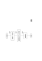
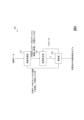
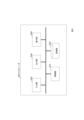
- FIG. 1 is a functional block diagram of a noise removal system according to a first embodiment.
- FIG. 2 is a diagram showing an example of a processing flow of the noise removal system according to the first embodiment.
- FIG. 2 is a functional block diagram of a training data generating device.
- FIG. 4 is a diagram showing an example of a processing flow of the training data generating device. Schematic diagram of the simulation used to generate training data.
- FIG. 2 is a functional block diagram of the learning device.
- FIG. 11 is a diagram showing an example of a processing flow of a learning device.
- FIG. 2 is a functional block diagram of a noise reduction device.
- FIG. 4 is a diagram showing an example of a processing flow of a noise removal device.
- FIG. 11 is a diagram showing an example of a noise removal result.
- FIG. 13 is a diagram showing an example of the configuration of a computer to which the present technique is applied.
- a highly accurate noise removal is achieved by using a deep neural network (DNN).
- DNN deep neural network
- the sound field moving image is expressed as a complex amplitude by Fourier transform, and in order to make it easier to handle with DNN, the sound field image expressed as a complex amplitude (hereinafter also referred to as a complex amplitude sound field image) is regarded as a two-channel image consisting of a real part and an imaginary part. This allows any DNN for image noise removal to be used for the purpose of sound field noise removal.
- training data is generated using acoustic simulation.
- FIG. 1 shows an example of the configuration of a noise reduction system according to a first embodiment
- Fig. 2 shows a process flow of the noise reduction system.
- the noise removal system includes a training data generating device 100, a learning device 200, and a noise removal device 300.
- the training data generating device 100 generates training data consisting of a set of correct answer data and learning input data (S100) and outputs the training data.
- the correct answer data is noise-free data generated using acoustic simulation
- the learning input data is noise-containing data.
- the learning device 200 receives training data as input, learns a noise removal model (S200), and outputs the learned noise removal model.
- the noise removal model is made of a DNN, receives information based on a complex amplitude sound field image for a sound field image as input, and outputs information based on the complex amplitude sound field image for a sound field image from which noise contained in the sound field image has been removed.
- the noise reduction device 300 receives a trained noise reduction model before noise reduction processing.
- the noise reduction device 300 receives as input a sound field moving image to be processed, removes noise contained in the sound field moving image (S300), and outputs the sound field moving image after noise reduction.
- a sound field moving image is composed of time-series sound field images, and it can also be said that the noise reduction device 300 receives as input sound field images constituting the sound field moving image to be processed, removes noise contained in the sound field images constituting the sound field moving image, and outputs sound field images constituting the sound field moving image after noise reduction.
- the training data generating device 100, the learning device 200, and the noise elimination device 300 are special devices configured by loading special programs into a publicly known or dedicated computer having, for example, a central processing unit (CPU), a main memory (RAM), etc.
- the training data generating device 100, the learning device 200, and the noise elimination device 300 execute each process under the control of, for example, the central processing unit.
- Data input to the training data generating device 100, the learning device 200, and the noise elimination device 300 and data obtained by each process are stored, for example, in the main memory, and the data stored in the main memory is read out to the central processing unit as necessary and used for other processes.
- each processing unit of the training data generating device 100, the learning device 200, and the noise elimination device 300 may be configured by hardware such as an integrated circuit.
- Each storage unit provided in the training data generating device 100, the learning device 200, and the noise reduction device 300 can be configured, for example, as a main storage device such as a RAM (Random Access Memory), or middleware such as a relational database or a key-value store.
- each storage unit does not necessarily need to be provided inside the training data generating device 100, the learning device 200, and the noise reduction device 300, but may be configured as an auxiliary storage device made up of a hard disk, optical disk, or semiconductor memory element such as a flash memory, and provided outside the training data generating device 100, the learning device 200, and the noise reduction device 300.
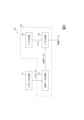
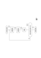
- FIG. 3 is a functional block diagram of the training data generating device 100, and FIG. 4 shows an example of the processing flow thereof.
- the training data generation device 100 includes a parameter generation unit 110, a correct answer data generation unit 120, a noise generation unit 130, and a noise addition unit 140.
- any theoretical formula or numerical simulation method that can numerically calculate the sound field data can be used.
- any parameter of the generation method is determined from a desired probability distribution to generate diverse learning data.
- One example is the following method.
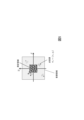
- Figure 5 shows a schematic diagram of the simulation.
- the inner rectangle is the measurement area
- the outer rectangle is the sound source area, in which point sound sources are randomly placed.
- the number of point sound sources is set to 1 to 5, and the position and relative amplitude of each sound source are randomly assigned.
- the ground truth data is a superposition of sound waves generated from these point sound sources, and is calculated using the following formula.
- r (x, y) is the position
- k is the magnitude of the acoustic wave number
- A is a constant that determines the size of the entire sound field
- N is the number of sound sources
- a i and r i (x i , y i ) are the relative amplitude and position of the i-th sound source, respectively
- H (2) 0 is the zero-order second-order Hankel function.
- the part inside the summation symbol represents the product of the relative amplitude of the i-th sound source and the Green's function of the two-dimensional Helmholtz equation.
- Ground-truth data is generated by generating parameters from the desired probability distribution and calculating the sound pressure at each point based on the above equation.
- the parameter generating unit 110 generates and outputs parameters used when generating ground truth data (S110). Possible parameters include the relative amplitude a i and position r i of each sound source. For example, the position of each sound source is randomly assigned according to a desired probability distribution from within the sound source region, and the relative amplitude is randomly assigned to each sound source according to a desired probability distribution from within the range of expected relative amplitudes. Note that the number of measurement regions, sound source regions, and point sound sources is assumed to be given in advance.
- the correct data generating unit 120 receives the parameters generated by the parameter generating unit 110 as input, and generates correct data by acoustic simulation using the parameters (S120), and outputs it. For example, while changing the number N of sound sources from 1 to 5, the relative amplitude a i and position r i of each sound source are input, and the sound pressure at each point in the measurement area is calculated by equation (1), and correct data is generated.
- Noise Adder 140 Any noise can be added according to the measurement system that acquires the sound field moving image. For example, additive Gaussian white noise can be added. White noise with a desired amplitude is generated and added to the ground truth data to generate noisy data.
- the noise generation unit 130 generates and outputs any noise (S130) in accordance with the measurement system that acquires the sound field moving image. For example, additive Gaussian white noise is generated.
- the noise adding unit 140 receives the correct answer data and the generated noise as input, adds the generated noise to the correct answer data (S140), uses the correct answer data with the added noise as learning input data, and outputs training data consisting of a pair of the correct answer data and the learning input data.
- the noise is added by adding white noise.
- the supervised data generating unit 120, the noise generating unit 130 and the noise adding unit 140 are collectively referred to as a training data generating unit 150, and the processing in the training data generating unit 150 is also referred to as a training data generation process S150.
- speckle noise can be added.
- the speckle noise data can be generated using, for example, the method described in Reference 1.
- the method of generating data including noise is arbitrary and is not limited to these.
- the training data generation unit 150 receives the parameters generated by the parameter generation unit 110 as input, generates correct answer data by acoustic simulation using the parameters, and generates correct answer data to which speckle noise has been added in the middle of the algorithm for generating the correct answer data (S150).
- This configuration makes it possible to generate large amounts of training data through acoustic simulation without extensive, time-consuming experiments.
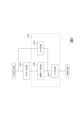
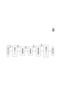
- FIG. 6 shows a functional block diagram of the learning device 200
- FIG. 7 shows an example of a processing flow thereof.
- the learning device 200 includes an image conversion unit 210, a noise removal unit 220, and an update unit 230.
- the image conversion unit 210 receives training data as input.
- the learning input data and the correct answer data included in the training data are complex amplitude sound field images.
- the elements of the complex amplitude sound field image represent complex amplitudes at corresponding spatial positions and Fourier frequencies.
- the image conversion unit 210 converts each complex amplitude sound field image into a two-channel image consisting of a real part and an imaginary part (S210).
- the image conversion unit 210 converts the complex amplitude sound field image [a 1 , ..., a K ] into an image consisting of a real part (hereinafter also referred to as a real part image) [b 1 , ..., b K ] and an image consisting of an imaginary part (hereinafter also referred to as an imaginary part image) [c 1 , ..., c K ].
- the image conversion unit 210 normalizes the two-channel images (real part image [ b1 , ..., bK ] and imaginary part image [ c1 , ..., cK ]) and outputs them.
- the normalization performed here is a process of preparing the data so that it can be easily handled by the noise removal model, and is a process of multiplying the data by a normalization coefficient.
- the noise removal unit 220 receives the learning input data included in the training data as input, removes noise from the learning input data using a noise removal model (S220), and obtains and outputs the learning input data after noise removal.
- S220 noise removal model
- the noise elimination unit 220 receives as input a two-channel image (real part image [b T,1 , ..., b T,K ] and imaginary part image [c T,1 , ..., c T,K ]) obtained by converting the learning input data (complex amplitude sound field image) included in the training data, and uses a noise elimination model to remove noise from the two-channel image (real part image [b T,1 , ..., b T,K ] and imaginary part image [c T,1 , ..., c T,K ]) to obtain a two-channel image (real part image [b' T,1 , ..., b' T,K ] and imaginary part image [c' T,1 , ..., c' T,K ]) after noise elimination.
- a two-channel image real part image [b T,1 , ..., b T,K ] and imaginary part image [c T,1 , ..., c' T,K ]
- the noise elimination model is made of a DNN, and receives as input information based on a complex amplitude sound field image for the sound field image, and outputs information based on the complex amplitude sound field image for the sound field image from which the noise included in the sound field image has been removed.
- the noise removal model is a model that receives normalized real part images and imaginary part images as input, removes noise contained in the real part images and imaginary part images, and outputs the real part images and imaginary part images after noise removal.
- any network that removes image noise can be used.
- a network with a Unet structure can be used.
- a nonlinear activation free network (NAFNet) (see Reference 2), which has excellent performance in removing image noise and can operate with relatively small memory and learning time, can also be used.
- NAFNet nonlinear activation free network
- the update unit 230 receives as input the correct answer data included in the training data and the learning input data after noise removal, and updates the parameters of the noise removal model so as to reduce the error between the correct answer data included in the training data and the learning input data after noise removal (S230).
- the ground truth data (complex amplitude sound field image) included in the training data is converted into a two-channel image, and the parameters of the noise removal model are updated so that the error between the normalized image and the two-channel image after noise removal (real part image [ b'T,1 , ..., b'T ,K ] and imaginary part image [c'T ,1 , ..., c'T ,K ]) is reduced.
- RMSE Root Mean Square Error
- the steepest descent method, Adam, etc. can be used for the optimization algorithm.
- the update unit 230 outputs the updated parameters to the noise reduction unit 220 and repeats S210 to S230.
- the update unit 230 outputs the noise removal model at that time as the trained noise removal model.
- the specified condition can be set to determine whether the parameter updates have converged. For example, conditions such as: has the learning been repeated a certain number of times (e.g., several times)? Is the difference in parameters before and after the update below a specified threshold? Is the loss below a specified threshold? can be used.
- any DNN for image noise removal can be used for the purpose of sound field noise removal.
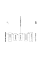
- FIG. 8 shows a functional block diagram of the noise elimination device 300
- FIG. 9 shows an example of the processing flow thereof.
- the noise reduction device 300 includes a Fourier transform unit 310, an image conversion unit 320, a noise reduction unit 330, an image inverse conversion unit 340, and an inverse Fourier transform unit 350.
- the noise removal device 300 uses the trained noise removal model in the noise removal unit 330 during noise removal processing.
- the Fourier transform unit 310 receives the sound field moving image to be processed, performs a time domain Fourier transform on all pixels of the sound field moving image (S310), and obtains and outputs a complex amplitude sound field image for each frequency.
- a fast Fourier transform or the like can be used as the Fourier transform.
- the image conversion unit 320 receives a complex amplitude sound field image for each frequency, converts the complex amplitude sound field image into a two-channel image consisting of a real part and an imaginary part (S320), normalizes the two-channel image, and outputs it.
- the image conversion unit 320 performs the same process as the image conversion unit 210.
- the noise removal unit 330 receives as input a sound field image for the sound field moving image to be processed, removes noise from the sound field moving image to be processed using a noise removal model (S330), and obtains and outputs a sound field image for the sound field moving image to be processed after noise removal.
- S330 noise removal model
- the noise removal unit 330 receives as input two-channel images (real part image [b E,1 , ..., b E,K ] and imaginary part image [c E,1 , ..., c E,K ]) obtained by converting the complex amplitude sound field image for the sound field moving image to be processed, and uses a noise removal model to remove noise from the two-channel images to obtain two-channel images after noise removal (real part image [b' E,1 , ..., b' E,K ] and imaginary part image [c' E,1 , ..., c' E,K ]).
- the image inverse conversion unit 340 receives the two-channel image after noise removal (real part image [b' E,1 , ..., b' E,K ] and imaginary part image [c' E,1 , ..., c' E,K ]) as input, and in order to maintain the size of the sound field, multiplies the two-channel image after noise removal (real part image [b' E,1 , ..., b' E,K ] and imaginary part image [c' E,1 , ..., c' E,K ]) by the reciprocal of the normalization coefficient multiplied by the image conversion unit 210 described above.
- the image inverse conversion unit 340 converts the two-channel image after noise removal (real part image [b' E,1 , ..., b' E,K ] and imaginary part image [c' E,1 , ..., c' E,K ]) into a complex amplitude sound field image [a' E,1 , ..., a' E,K ] (S340) and outputs it.
- the image inverse conversion unit 340 converts an image consisting of a real part (hereinafter also referred to as the real part image) [ b1 , ..., bK ] and an image consisting of an imaginary part (hereinafter also referred to as the imaginary part image) [ c1 , ..., cK ] into a complex amplitude sound field image [ a1 , ..., aK ].
- the inverse Fourier transform unit 350 receives the complex amplitude sound field image [a'E ,1 ,...,a'E ,K ], performs inverse Fourier transform in the time direction (S350), and obtains and outputs a noise-removed sound field moving image.
- a transform method corresponding to the Fourier transform performed by the above-mentioned Fourier transform unit 310 may be used.
- NAFNet the same network as in Reference 1, except for the number of image channels.
- the network consisted of blocks 32 wide, with two image channels (real image, imaginary image), and an image size of 128 x 128.
- RMSE root mean square error
- Adam was used as the optimization algorithm, and the learning rate was set to 0.001.
- a total of 2,000 pieces of training data were created, with 400 pieces for each number of sound sources.
- the training batch size was 32, and the number of epochs was 50.
- Additive white Gaussian noise was used as noise.
- FIG. 10 shows an example of the noise removal result. It can be seen that the noise removal according to this embodiment significantly removes noise contained in the noisy data.
- the noise elimination device 300 receives a sound field moving image to be processed, removes noise contained in the sound field moving image (S300), and outputs the sound field moving image after the noise elimination.
- the processing target may be a single sound field image instead of a sound field moving image.
- the noise elimination device 300 receives a sound field image to be processed, removes noise contained in the sound field image (S300), and outputs the sound field image after the noise elimination.
- the noise elimination unit 220 receives at least the real part image [b T,1 , ..., b T,K ] included in the two-channel image (real part image [b T,1 , ..., b T,K ] and imaginary part image [c T,1 , ..., c T,K ]) obtained by converting the learning input data (complex amplitude sound field image) included in the training data as input, and removes noise from the real part image [b T,1 , ... , b T,K ] using a noise elimination model to obtain a real part image [b' T,1 , ..., b' T,K ] after noise elimination.
- the noise elimination model is made of a DNN, receives a sound field image (real part image) as input, and outputs a sound field image (real part image) from which noise contained in the sound field image (real part image) has been removed.
- the noise elimination model receives a normalized real part image as input, removes noise contained in the real part image, and outputs the real part image after noise elimination.
- a DNN is used to remove noise from a one-channel input image (real part image), so any network that removes noise from an image can be used, as in the first embodiment.
- the update unit 230 receives as input the correct answer data included in the training data and the learning input data after noise removal, and updates the parameters of the noise removal model so as to reduce the error between the real part of the correct answer data included in the training data and the learning input data after noise removal (real part image) (S230).
- the noise removal model is a model that receives as input the amplitude and phase corresponding to a complex amplitude sound field image, and outputs the amplitude and phase corresponding to a complex amplitude sound field image after noise removal.
- the image conversion unit 210 of the learning device 200 receives training data as input.
- the learning input data and correct answer data included in the training data are each a complex amplitude sound field image.
- the elements of the complex amplitude sound field image represent complex amplitudes at corresponding spatial positions and Fourier frequencies.
- the image conversion unit 210 converts each complex amplitude sound field image into amplitude and phase (S210).
- the image conversion unit 210 performs normalization processing (processing to arrange data so that it is easy to handle with a noise reduction model) as necessary.
- the noise removal unit 220 of the learning device 200 receives as input the learning input data included in the training data, removes noise from the learning input data using a noise removal model (S220), and obtains and outputs the learning input data after noise removal.
- S220 noise removal model
- the noise removal unit 220 receives as input the amplitude and phase obtained by converting the learning input data (complex amplitude sound field image) included in the training data, removes noise from the complex amplitude sound field image using a noise removal model, and obtains the amplitude and phase corresponding to the complex amplitude sound field image after noise removal.
- a network similar to that in the first embodiment can be used.
- a network with a Unet structure can be used, similar to that in the first embodiment. It is also possible to use NAFNet.
- the update unit 230 of the learning device 200 receives as input the correct answer data included in the training data and the learning input data after noise removal, and updates the parameters of the noise removal model so as to reduce the error between the correct answer data included in the training data and the learning input data after noise removal (S230).
- the parameters of the noise removal model are updated so that the error between the amplitude and phase corresponding to the correct answer data (complex amplitude sound field image) included in the training data and the amplitude and phase corresponding to the complex amplitude sound field image after noise removal is reduced.
- the parameters can be updated in the same manner as in the first embodiment.
- the image conversion unit 320 of the noise reduction device 300 receives a complex amplitude sound field image for each frequency, converts the complex amplitude sound field image into amplitude and phase (S320), and outputs the converted image.
- the image conversion unit 320 performs the same process as the image conversion unit 210.
- the noise removal unit 330 of the noise removal device 300 receives as input a sound field image for the sound field moving image to be processed, removes noise from the sound field moving image to be processed using a noise removal model (S330), and obtains and outputs a sound field image for the sound field moving image to be processed after noise removal.
- S330 noise removal model
- the noise removal unit 330 receives as input the amplitude and phase obtained by converting a complex amplitude sound field image for the sound field moving image to be processed, removes noise from the complex amplitude sound field image using a noise removal model, and obtains the amplitude and phase corresponding to the complex amplitude sound field image after noise removal.
- the image inverse conversion unit 340 receives the amplitude and phase corresponding to the complex amplitude sound field image after noise removal, converts the amplitude and phase corresponding to the complex amplitude sound field image after noise removal into a complex amplitude sound field image (S340), and outputs it. If normalization processing has been performed in the image conversion unit 210, a process of returning it to its original state is performed.
- the noise removal model is a DNN (complex neural network) that receives complex numbers as input, receives a complex amplitude sound field image as input, and outputs a complex amplitude sound field image after noise removal.
- the learning device 200 includes a noise removal unit 220 and an update unit 230.
- the noise elimination unit 220 receives the learning input data included in the training data as input, and removes noise from the learning input data using a noise elimination model (S220), obtains the learning input data after the noise elimination, and outputs it. Note that, if necessary, a normalization process (a process of adjusting the data to be easier to handle with the noise elimination model) is performed on the learning input data.
- the noise removal unit 220 receives learning input data (complex amplitude sound field image) included in the training data as input, removes noise from the complex amplitude sound field image using a noise removal model, and obtains a complex amplitude sound field image after noise removal.
- a DNN is used to remove noise from complex amplitude sound field images, so any complex neural network that removes noise from images can be used.
- the update unit 230 receives as input the correct answer data included in the training data and the learning input data after noise removal, and updates the parameters of the noise removal model so as to reduce the error between the correct answer data included in the training data and the learning input data after noise removal (S230).
- the parameters of the noise removal model are updated so that the error between the correct answer data (complex amplitude sound field image) included in the training data and the complex amplitude sound field image after noise removal is reduced.
- the noise reduction device 300 includes a Fourier transform section 310 , a noise reduction section 330 and an inverse Fourier transform section 350 .
- the noise elimination unit 330 receives a sound field image for the sound field moving image to be processed as an input, removes noise from the sound field moving image to be processed using a noise elimination model (S330), obtains a sound field image for the sound field moving image to be processed after the noise elimination, and outputs it. Note that, like the noise elimination unit 220, it performs normalization processing (processing to arrange data so that it is easy to handle by the noise elimination model) on the learning input data as necessary, and performs processing to restore the output of the noise elimination model.
- normalization processing processing to arrange data so that it is easy to handle by the noise elimination model
- the noise removal unit 330 receives as input a complex amplitude sound field image for the sound field moving image to be processed, removes noise from the complex amplitude sound field image using a noise removal model, and obtains a complex amplitude sound field image after noise removal.
- the noise removal model can be said to be a model that receives information based on a complex amplitude sound field image for a sound field image as input, and outputs information based on the complex amplitude sound field image for a sound field moving image from which noise contained in the sound field image has been removed.
- the real part image and the imaginary part image correspond to information based on the complex amplitude sound field image
- the real part image corresponds to information based on the complex amplitude sound field image
- the phase and amplitude correspond to information based on the complex amplitude sound field image
- the complex amplitude sound field image itself corresponds to information based on the complex amplitude sound field image.
- the image conversion unit 210 of the first embodiment may be considered as pre-processing and post-processing of the noise removal unit 220, and the image conversion unit 210 may be considered as part of the noise removal unit 220.
- the image conversion unit 320 and the image inverse conversion unit 340 of the first embodiment may be considered as pre-processing and post-processing of the noise removal unit 330, respectively, and the image conversion unit 320 and the image inverse conversion unit 340 may be considered as part of the noise removal unit 330.
- the second modification may be considered as pre-processing and post-processing of the noise removal unit 220, and the image conversion unit 210 may be considered as part of the noise removal unit 220.
- the image conversion unit 320 and the image inverse conversion unit 340 of the first embodiment may be considered as pre-processing and post-processing of the noise removal unit 330, respectively, and the image conversion unit 320 and the image inverse conversion unit 340 may be considered as part of the noise removal unit 330.
- the second modification may be considered as pre-
- the present invention is not limited to the above-mentioned embodiment and modified examples.
- the above-mentioned various processes may be executed not only in chronological order as described, but also in parallel or individually depending on the processing capacity of the device executing the processes or as necessary.
- appropriate modifications are possible within the scope of the present invention.
- ⁇ Program and recording medium> The various processes described above can be implemented by loading a program that executes each step of the above method into the recording unit 2020 of the computer 2000 shown in FIG. 11, and operating the control unit 2010, input unit 2030, output unit 2040, display unit 2050, etc.
- the program describing this processing can be recorded on a computer-readable recording medium.
- Examples of computer-readable recording media include magnetic recording devices, optical disks, magneto-optical recording media, and semiconductor memories.
- the program may be distributed, for example, by selling, transferring, or lending portable recording media such as DVDs or CD-ROMs on which the program is recorded. Furthermore, the program may be distributed by storing the program in a storage device of a server computer and transferring the program from the server computer to other computers via a network.
- a computer that executes such a program for example, first stores in its own storage device the program recorded on a portable recording medium or the program transferred from a server computer. Then, when executing a process, the computer reads the program stored on its own recording medium and executes the process according to the read program. As another execution form of the program, the computer may read the program directly from the portable recording medium and execute the process according to the program, or may execute the process according to the received program each time a program is transferred from the server computer to the computer.
- the above-mentioned process may also be executed by a so-called ASP (Application Service Provider) type service that does not transfer the program from the server computer to the computer, but realizes the processing function only by issuing an execution instruction and obtaining the results.
- ASP Application Service Provider
- the program in this form includes information used for processing by an electronic computer that is equivalent to a program (such as data that is not a direct command to the computer but has properties that specify the processing of the computer).
- the device is configured by executing a specific program on a computer, but at least a portion of the processing may be realized by hardware.
Landscapes
- Physics & Mathematics (AREA)
- Engineering & Computer Science (AREA)
- Acoustics & Sound (AREA)
- Signal Processing (AREA)
- Soundproofing, Sound Blocking, And Sound Damping (AREA)
Abstract
従来技術よりも高精度に音場動画像の雑音除去を行い、性質が未知のデータや、非線形雑音を含むデータに対しても良好な雑音除去を行うことができる雑音除去装置等を提供する。雑音除去装置は、DNNからなり、音場画像を入力とし、音場画像に含まれるノイズを除去した音場画像を出力する。
Description
本発明は、音場イメージング技術に関する。
音場イメージングは、空間中の音を測定し、動画像として可視化する技術であり、マイクロホンアレイや光計測装置等を用いて行われる。音場動画像は、動画像の各ピクセルの値が測定空間中の音の振幅に対応する値となった離散データであり、音の時空間的な挙動や音響現象を観測および測定するのに用いられる。
音場動画像に関する信号処理タスクのひとつに雑音除去がある。非特許文献1では、音場動画像に対して時空間周波数フィルタリングを用いて雑音除去を行う。測定対象である音の物理的な性質に合わせて設計したフィルタを用いることで、雑音を除去し、音信号を強調することが可能である。
N. Chitanont, K. Yatabe, K. Ishikawa, and Y. Oikawa, "Spatio-temporal filter bank for visualizing audible sound field by schlieren method", Appl. Acoust. 115, 109-120 (2017).
しかしながら、従来技術には、雑音除去性能に一定の限界があり、事前に音信号の性質を知っている必要があり、非線形雑音の除去には適さないなどの課題がある。
本発明は、従来技術よりも高精度に音場動画像の雑音除去を行い、性質が未知のデータや、非線形雑音を含むデータに対しても良好な雑音除去を行うことができる雑音除去装置、雑音除去装置で用いるモデルの学習装置、学習装置で用いる訓練データを生成する訓練データ生成装置を提供することを目的とする。
上記の課題を解決するために、本発明の一態様によれば、雑音除去装置は、DNNからなり、音場画像を入力とし、その音場画像に含まれるノイズを除去した音場画像を出力する。
上記の課題を解決するために、本発明の他の態様によれば、学習装置は、DNNからなり、音場画像に対する複素振幅音場画像に基づく情報を入力とし、音場画像に含まれるノイズを除去した音場画像に対する複素振幅音場画像に基づく情報を出力する雑音除去モデルを用いて、訓練データに含まれる学習用入力データに対する音場画像からノイズを除去し、ノイズ除去後の学習用入力データを得る雑音除去部と、訓練データに含まれる正解データとノイズ除去後の学習用入力データとの誤差が小さくなるように、雑音除去モデルのパラメータを更新する更新部と、を含む。
上記の課題を解決するために、本発明の他の態様によれば、訓練データ生成装置は、正解データを生成する際に用いるパラメータを生成するパラメータ生成部と、パラメータを用いて音響シミュレーションにより、正解データを生成し、音場動画像を取得する計測システムに合わせて、任意のノイズを付加した正解データを学習用入力データとし、正解データと学習用入力データとの組からなる訓練データを得る訓練データ生成部とを含み、訓練データは、DNNからなり、音場画像に対する複素振幅音場画像に基づく情報を入力とし、音場画像に含まれるノイズを除去した音場画像に対する複素振幅音場画像に基づく情報を出力する雑音除去モデルを学習する際に用いられる。
本発明によれば、音場動画像の雑音除去を従来技術よりも高精度にすることができ、性質が未知のデータや、非線形雑音を含むデータに対しても良好な雑音除去を行うことができるという効果を奏する。
以下、本発明の実施形態について、説明する。なお、以下の説明に用いる図面では、同じ機能を持つ構成部や同じ処理を行うステップには同一の符号を記し、重複説明を省略する。以下の説明において、テキスト中で使用する記号「^」等は、本来直前の文字の真上に記載されるべきものであるが、テキスト記法の制限により、当該文字の直後に記載する。式中においてはこれらの記号は本来の位置に記述している。また、ベクトルや行列の各要素単位で行われる処理は、特に断りが無い限り、そのベクトルやその行列の全ての要素に対して適用されるものとする。
<第一実施形態のポイント>
本実施形態では、DNN(Deep Neural Network)を用いて、高精度な雑音除去を実現する。DNNを用いることで、性質が未知のデータや、非線形雑音を含むデータに対しても良好な雑音除去を行うことができる。
本実施形態では、DNN(Deep Neural Network)を用いて、高精度な雑音除去を実現する。DNNを用いることで、性質が未知のデータや、非線形雑音を含むデータに対しても良好な雑音除去を行うことができる。
本実施形態では、音場動画像をフーリエ変換によって複素振幅として表現し、DNNで扱いやすくするために複素振幅で表現される音場画像(以下、複素振幅音場画像ともいう)を実部と虚部からなる2チャンネル画像とみなす。これによって、任意の画像ノイズ除去用DNNを音場雑音除去の目的に用いることができる。
DNNを学習するためには、大量の訓練データを必要とするが、音場動画像に関して、実験で雑音を含まないデータと雑音を含むデータの対を大量に収集することは極めて困難である。そこで、本実施形態では、音響シミュレーションを用いて訓練データを生成する。
<第一実施形態>
図1は第一実施形態に係る雑音除去システムの構成例を示す。図2は雑音除去システムの処理フローを示す。
図1は第一実施形態に係る雑音除去システムの構成例を示す。図2は雑音除去システムの処理フローを示す。
雑音除去システムは、訓練データ生成装置100、学習装置200および雑音除去装置300を含む。
訓練データ生成装置100は、正解データと学習用入力データとの組からなる訓練データを生成し(S100)、出力する。なお、正解データは音響シミュレーションを用いて生成したノイズを含まないデータであり、学習用入力データはノイズを含むデータである。
学習装置200は、訓練データを入力とし、雑音除去モデルを学習し(S200)、学習済みの雑音除去モデルを出力する。雑音除去モデルは、DNNからなり、音場画像に対する複素振幅音場画像に基づく情報を入力とし、音場画像に含まれるノイズを除去した音場画像に対する複素振幅音場画像に基づく情報を出力するモデルである。
雑音除去装置300は、雑音除去処理の前に、学習済みの雑音除去モデルを受け取る。雑音除去装置300は、処理対象の音場動画像を入力とし、音場動画像に含まれる雑音を除去し(S300)、雑音除去後の音場動画像を出力する。音場動画像は、時系列の音場画像からなり、雑音除去装置300は、処理対象の音場動画像を構成する音場画像を入力とし、音場動画像を構成する音場画像に含まれる雑音を除去し、雑音除去後の音場動画像を構成する音場画像を出力するとも言える。
訓練データ生成装置100、学習装置200および雑音除去装置300は、例えば、中央演算処理装置(CPU: Central Processing Unit)、主記憶装置(RAM: Random Access Memory)などを有する公知又は専用のコンピュータに特別なプログラムが読み込まれて構成された特別な装置である。訓練データ生成装置100、学習装置200および雑音除去装置300は、例えば、中央演算処理装置の制御のもとで各処理を実行する。訓練データ生成装置100、学習装置200および雑音除去装置300に入力されたデータや各処理で得られたデータは、例えば、主記憶装置に格納され、主記憶装置に格納されたデータは必要に応じて中央演算処理装置へ読み出されて他の処理に利用される。訓練データ生成装置100、学習装置200および雑音除去装置300の各処理部は、少なくとも一部が集積回路等のハードウェアによって構成されていてもよい。訓練データ生成装置100、学習装置200および雑音除去装置300が備える各記憶部は、例えば、RAM(Random Access Memory)などの主記憶装置、またはリレーショナルデータベースやキーバリューストアなどのミドルウェアにより構成することができる。ただし、各記憶部は、必ずしも訓練データ生成装置100、学習装置200および雑音除去装置300がその内部に備える必要はなく、ハードディスクや光ディスクもしくはフラッシュメモリ(Flash Memory)のような半導体メモリ素子により構成される補助記憶装置により構成し、訓練データ生成装置100、学習装置200および雑音除去装置300の外部に備える構成としてもよい。
以下、各装置について説明する。
<訓練データ生成装置100>
図3は訓練データ生成装置100の機能ブロック図を、図4はその処理フローの例を示す。
図3は訓練データ生成装置100の機能ブロック図を、図4はその処理フローの例を示す。
訓練データ生成装置100は、パラメータ生成部110、正解データ生成部120、ノイズ生成部130およびノイズ付加部140を含む。
<パラメータ生成部110および正解データ生成部120>
正解データの生成には,音場データを数値的に計算することのできる任意の理論式・数値シミュレーション方法を用いることができる。データ作成に際して、生成手法の任意のパラメータを所望の確率分布から決定することで多様性な学習データを生成する。一例として次のような方法がある。
正解データの生成には,音場データを数値的に計算することのできる任意の理論式・数値シミュレーション方法を用いることができる。データ作成に際して、生成手法の任意のパラメータを所望の確率分布から決定することで多様性な学習データを生成する。一例として次のような方法がある。
パラメータをランダム化した2次元音場シミュレーションを使用する。図5はシミュレーションの模式図である。内側の長方形が測定領域で、その外側が音源領域となり、点音源がランダムに配置されている。単純なものから複雑なものまで多様な空間特性を持つ音場を生成するために、点音源の数は1~5個とし、各音源の位置と相対振幅をランダムに割り当てる。正解データは、これらの点音源から発生する音波の重ね合わせであり、次の式で計算される。

ここで、r=(x,y)は位置、kは音響波数の大きさ、Aは音場全体の大きさを決める定数、Nは音源の数、aiとri=(xi, yi)はそれぞれi番目の音源の相対振幅と位置、H(2)
0は0次第2種ハンケル関数である。総和記号の内部はi番目の音源の相対振幅と2次元ヘルムホルツ方程式のグリーン関数の積を表している。パラメータを所望の確率分布から生成し、上式に基づいて各点の音圧を計算することで、正解データを生成する。
パラメータ生成部110は、正解データを生成する際に用いるパラメータを生成し(S110)、出力する。パラメータとしては、各音源の相対振幅aiと位置ri等が考えられる。例えば、音源領域の中から所望の確率分布に従ってランダムに各音源の位置を割り当て、想定される相対振幅の範囲の中から所望の確率分布に従ってランダムに各音源に相対振幅を割り当てる。なお、測定領域、音源領域および点音源の個数は予め与えられているものとする。
正解データ生成部120は、パラメータ生成部110で生成されたパラメータを入力とし、パラメータを用いて音響シミュレーションにより、正解データを生成し(S120)、出力する。例えば、音源の個数Nを1~5に変えながら、各音源の相対振幅aiと位置riを入力とし、式(1)により、測定領域の各点における音圧を求め、正解データを生成する。
<ノイズ生成部130およびノイズ付加部140>
音場動画像を取得する計測システムに合わせて、任意のノイズが与えることができる。例えば、加法性ガウスホワイトノイズである。所望の振幅を有するホワイトノイズ生成し、正解データに加算することで、ノイズありデータを生成する。
音場動画像を取得する計測システムに合わせて、任意のノイズが与えることができる。例えば、加法性ガウスホワイトノイズである。所望の振幅を有するホワイトノイズ生成し、正解データに加算することで、ノイズありデータを生成する。
ノイズ生成部130は、音場動画像を取得する計測システムに合わせて、任意のノイズを生成し(S130)、出力する。例えば、加法性ガウスホワイトノイズが生成される。
ノイズ付加部140は、正解データと生成されたノイズを入力とし、正解データに生成されたノイズを付加し(S140)、ノイズを付加した正解データを学習用入力データとし、正解データと学習用入力データとの組からなる訓練データを出力する。例えば、ホワイトノイズを加算することで、ノイズを付加する。
正解データ生成部120、ノイズ生成部130およびノイズ付加部140を合わせて訓練データ生成部150ともいい、訓練データ生成部150における処理を訓練データ生成処理S150ともいう。
正解データ生成部120、ノイズ生成部130およびノイズ付加部140を合わせて訓練データ生成部150ともいい、訓練データ生成部150における処理を訓練データ生成処理S150ともいう。
また、スペックル干渉計と呼ばれる光学システムを用いる音場イメージング結果の雑音除去を考える場合、スペックルノイズを付加することもできる。スペックルノイズデータの生成方法は、例えば参考文献1の方法などを用いることができる。ただしノイズを含むデータの生成方法は任意であり、これらに限定するものではない。
(参考文献1)Q. Fang, H. Xia, Q. Song, M. Zhang, R. Guo, S. Montresor, and P. Picart, "Speckle denoising based on deep learning via a conditional generative adversarial network in digital holographic interferometry", Opt. Express 30, 20666-20683 (2022).
例えば、スペックルノイズデータの生成方法する場合、訓練データ生成部150は、パラメータ生成部110で生成されたパラメータを入力とし、パラメータを用いて音響シミュレーションにより、正解データを生成し、正解データを生成するアルゴリズムの途中でスペックルノイズを付加した正解データを生成する(S150)。
このような構成とすることで、膨大な手間や時間のかかる実験なしに、音響シミュレーションによって大量の訓練データを生成することができる。
<学習装置200>
図6は学習装置200の機能ブロック図を、図7はその処理フローの例を示す。
図6は学習装置200の機能ブロック図を、図7はその処理フローの例を示す。
学習装置200は、画像変換部210、雑音除去部220および更新部230を含む。
<画像変換部210>
画像変換部210は、訓練データを入力とする。訓練データに含まれる学習用入力データと正解データは、それぞれ複素振幅音場画像である。複素振幅音場画像の要素は、対応する空間位置とフーリエ周波数における複素振幅を表す。画像変換部210は、各複素振幅音場画像を実部と虚部からなる2チャンネル画像に変換する(S210)。例えば、複素振幅音場画像がK個の要素からなり、[a1,…,aK]と表現され、k番目の要素がak=bk+ckjのとき、画像変換部210は、複素振幅音場画像[a1,…,aK]を、実部からなる画像(以下、実部画像ともいう)[b1,…,bK]と、虚部からなる画像(以下、虚部画像ともいう)[c1,…,cK]とに変換する。さらに、画像変換部210は、2チャンネル画像(実部画像[b1,…,bK]と虚部画像[c1,…,cK])を正規化し、出力する。なお、ここで行われる正規化は、データを雑音除去モデルで扱いやすいものに整える処理であり、データに正規化係数を乗じる処理である。
画像変換部210は、訓練データを入力とする。訓練データに含まれる学習用入力データと正解データは、それぞれ複素振幅音場画像である。複素振幅音場画像の要素は、対応する空間位置とフーリエ周波数における複素振幅を表す。画像変換部210は、各複素振幅音場画像を実部と虚部からなる2チャンネル画像に変換する(S210)。例えば、複素振幅音場画像がK個の要素からなり、[a1,…,aK]と表現され、k番目の要素がak=bk+ckjのとき、画像変換部210は、複素振幅音場画像[a1,…,aK]を、実部からなる画像(以下、実部画像ともいう)[b1,…,bK]と、虚部からなる画像(以下、虚部画像ともいう)[c1,…,cK]とに変換する。さらに、画像変換部210は、2チャンネル画像(実部画像[b1,…,bK]と虚部画像[c1,…,cK])を正規化し、出力する。なお、ここで行われる正規化は、データを雑音除去モデルで扱いやすいものに整える処理であり、データに正規化係数を乗じる処理である。
<雑音除去部220>
雑音除去部220は、訓練データに含まれる学習用入力データを入力とし、雑音除去モデルを用いて、学習用入力データからノイズを除去し(S220)、ノイズ除去後の学習用入力データを得、出力する。
雑音除去部220は、訓練データに含まれる学習用入力データを入力とし、雑音除去モデルを用いて、学習用入力データからノイズを除去し(S220)、ノイズ除去後の学習用入力データを得、出力する。
本実施形態では、雑音除去部220は、訓練データに含まれる学習用入力データ(複素振幅音場画像)を変換した2チャンネル画像(実部画像[bT,1,…,bT,K]と虚部画像[cT,1,…,cT,K])を入力とし、雑音除去モデルを用いて、2チャンネル画像(実部画像[bT,1,…,bT,K]と虚部画像[cT,1,…,cT,K])からノイズを除去し、ノイズ除去後の2チャンネル画像(実部画像[b'T,1,…,b'T,K]と虚部画像[c'T,1,…,c'T,K])を得る。なお、雑音除去モデルは、前述の通り、DNNからなり、音場画像に対する複素振幅音場画像に基づく情報を入力とし、音場画像に含まれるノイズを除去した音場画像に対する複素振幅音場画像に基づく情報を出力するモデルである。本実施形態では、雑音除去モデルは、実部画像と虚部画像を正規化したものを入力とし、実部画像と虚部画像に含まれるノイズを除去し、ノイズ除去後の実部画像と虚部画像を出力するモデルである。
本実施形態では、2チャンネルの入力画像のノイズ除去にDNNを用いるため、画像のノイズ除去を行うネットワークであれば利用可能である。例えば、Unet構造のネットワークが使える。また、画像ノイズ除去に優れた性能を持ち、比較的小さなメモリと学習時間で動作可能なNAFNet (Nonlinear activation free network) (参考文献2参照)を使うこともできる。
(参考文献2)L. Chen, X. Chu, X. Zhang, and J. Sun, "Simple baselines for image restoration", in Proceedings of the European 350 Conference on Computer Vision (ECCV), (Springer Nature Switzerland, Cham, 2022), pp. 17-33
(参考文献2)L. Chen, X. Chu, X. Zhang, and J. Sun, "Simple baselines for image restoration", in Proceedings of the European 350 Conference on Computer Vision (ECCV), (Springer Nature Switzerland, Cham, 2022), pp. 17-33
<更新部230>
更新部230は、訓練データに含まれる正解データとノイズ除去後の学習用入力データとを入力とし、訓練データに含まれる正解データと、ノイズ除去後の学習用入力データとの誤差が小さくなるように、雑音除去モデルのパラメータを更新する(S230)。
更新部230は、訓練データに含まれる正解データとノイズ除去後の学習用入力データとを入力とし、訓練データに含まれる正解データと、ノイズ除去後の学習用入力データとの誤差が小さくなるように、雑音除去モデルのパラメータを更新する(S230)。
本実施形態では、訓練データに含まれる正解データ(複素振幅音場画像)を2チャンネル画像に変換し、正規化したものと、ノイズ除去後の2チャンネル画像(実部画像[b'T,1,…,b'T,K]と虚部画像[c'T,1,…,c'T,K])との誤差が小さくなるように、雑音除去モデルのパラメータを更新する。例えば、ロスにはRMSE(Root Mean Square Error)を用い、最適化アルゴリズムには最急降下法、Adam等を用いることができる。
更新部230は、所定の条件を満たさない場合(S230-1のNO)、更新後のパラメータを雑音除去部220に出力し、S210~S230を繰り返す。
所定の条件を満たす場合(S230-1のYES)、更新部230は、その時点の雑音除去モデルを学習済みの雑音除去モデルとして出力する。
所定の条件としては、パラメータの更新が収束したか否かを判断するための条件を設定すればよく、例えば、学習を一定回数(例えば数回)繰り返したか?更新前後のパラメータの差分が所定の閾値以下か?損失が所定の閾値以下か?などの条件を利用できる。
このような学習方法を採用することで、任意の画像ノイズ除去用DNNを音場雑音除去の目的に用いることができる。
<雑音除去装置300>
図8は雑音除去装置300の機能ブロック図を、図9はその処理フローの例を示す。
図8は雑音除去装置300の機能ブロック図を、図9はその処理フローの例を示す。
雑音除去装置300は、フーリエ変換部310、画像変換部320、雑音除去部330、画像逆変換部340および逆フーリエ変換部350を含む。
雑音除去装置300は、学習済みの雑音除去モデルを雑音除去処理時に雑音除去部330で用いる。
<フーリエ変換部310>
フーリエ変換部310は、処理対象の音場動画像を入力とし、音場動画像の全画素に対して時間領域フーリエ変換を行い(S310)、周波数毎の複素振幅音場画像を得、出力する。フーリエ変換としては、高速フーリエ変換等を用いることができる。
フーリエ変換部310は、処理対象の音場動画像を入力とし、音場動画像の全画素に対して時間領域フーリエ変換を行い(S310)、周波数毎の複素振幅音場画像を得、出力する。フーリエ変換としては、高速フーリエ変換等を用いることができる。
<画像変換部320>
画像変換部320は、周波数毎の複素振幅音場画像を入力とし、複素振幅音場画像を実部と虚部からなる2チャンネル画像に変換し(S320)、2チャンネル画像を正規化し、出力する。例えば、画像変換部320は、画像変換部210と同様の処理を行う。
画像変換部320は、周波数毎の複素振幅音場画像を入力とし、複素振幅音場画像を実部と虚部からなる2チャンネル画像に変換し(S320)、2チャンネル画像を正規化し、出力する。例えば、画像変換部320は、画像変換部210と同様の処理を行う。
<雑音除去部330>
雑音除去部330は、処理対象の音場動画像に対する音場画像を入力とし、雑音除去モデルを用いて、処理対象の音場動画像からノイズを除去し(S330)、ノイズ除去後の処理対象の音場動画像に対する音場画像を得、出力する。
雑音除去部330は、処理対象の音場動画像に対する音場画像を入力とし、雑音除去モデルを用いて、処理対象の音場動画像からノイズを除去し(S330)、ノイズ除去後の処理対象の音場動画像に対する音場画像を得、出力する。
本実施形態では、雑音除去部330は、処理対象の音場動画像に対する複素振幅音場画像を変換した2チャンネル画像(実部画像[bE,1,…,bE,K]と虚部画像[cE,1,…,cE,K])を入力とし、雑音除去モデルを用いて、2チャンネル画像からノイズを除去し、ノイズ除去後の2チャンネル画像(実部画像[b'E,1,…,b'E,K]と虚部画像[c'E,1,…,c'E,K])を得る。
<画像逆変換部340>
画像逆変換部340は、ノイズ除去後の2チャンネル画像(実部画像[b'E,1,…,b'E,K]と虚部画像[c'E,1,…,c'E,K])を入力とし、音場の大きさを維持するために、ノイズ除去後の2チャンネル画像(実部画像[b'E,1,…,b'E,K]と虚部画像[c'E,1,…,c'E,K])に、前述の画像変換部210で乗じた正規化係数の逆数を乗じる。次に、画像逆変換部340は、ノイズ除去後の2チャンネル画像(実部画像[b'E,1,…,b'E,K]と虚部画像[c'E,1,…,c'E,K])を複素振幅音場画像[a'E,1,…,a'E,K]に変換し(S340)、出力する。例えば、複素振幅音場画像がK個の要素からなり、[a1,…,aK]と表現され、k番目の要素がak=bk+ckjのとき、画像逆変換部340は、実部からなる画像(以下、実部画像ともいう)[b1,…,bK]と、虚部からなる画像(以下、虚部画像ともいう)[c1,…,cK]とを、複素振幅音場画像[a1,…,aK]に変換する。
画像逆変換部340は、ノイズ除去後の2チャンネル画像(実部画像[b'E,1,…,b'E,K]と虚部画像[c'E,1,…,c'E,K])を入力とし、音場の大きさを維持するために、ノイズ除去後の2チャンネル画像(実部画像[b'E,1,…,b'E,K]と虚部画像[c'E,1,…,c'E,K])に、前述の画像変換部210で乗じた正規化係数の逆数を乗じる。次に、画像逆変換部340は、ノイズ除去後の2チャンネル画像(実部画像[b'E,1,…,b'E,K]と虚部画像[c'E,1,…,c'E,K])を複素振幅音場画像[a'E,1,…,a'E,K]に変換し(S340)、出力する。例えば、複素振幅音場画像がK個の要素からなり、[a1,…,aK]と表現され、k番目の要素がak=bk+ckjのとき、画像逆変換部340は、実部からなる画像(以下、実部画像ともいう)[b1,…,bK]と、虚部からなる画像(以下、虚部画像ともいう)[c1,…,cK]とを、複素振幅音場画像[a1,…,aK]に変換する。
<逆フーリエ変換部350>
逆フーリエ変換部350は、複素振幅音場画像[a'E,1,…,a'E,K]を入力とし、時間方向に逆フーリエ変換し(S350)、雑音除去された音場動画像を得、出力する。逆フーリエ変換としては、前述のフーリエ変換部310で行ったフーリエ変換に対応する変換方法を用いればよい。
逆フーリエ変換部350は、複素振幅音場画像[a'E,1,…,a'E,K]を入力とし、時間方向に逆フーリエ変換し(S350)、雑音除去された音場動画像を得、出力する。逆フーリエ変換としては、前述のフーリエ変換部310で行ったフーリエ変換に対応する変換方法を用いればよい。
<効果>
以上の構成により、音場動画像の雑音除去を従来技術よりも高精度にすることができ、性質が未知のデータや、非線形雑音を含むデータに対しても良好な雑音除去を行うことができる。
以上の構成により、音場動画像の雑音除去を従来技術よりも高精度にすることができ、性質が未知のデータや、非線形雑音を含むデータに対しても良好な雑音除去を行うことができる。
<雑音除去結果>
次に本実施形態に基づく実装例および雑音除去結果例を示す。
次に本実施形態に基づく実装例および雑音除去結果例を示す。
画像チャンネル数を除き、参考文献1と同じネットワークであるNAFNetを使用した。ネットワークは幅32のブロックからなり、画像チャンネル数は2(実部画像、虚部画像)、画像サイズは128 x 128とした。ロスにはRMSE(root mean square error)を、最適化アルゴリズムにはAdamを用い、学習率は0.001に設定した。学習データは、音源数ごとに 400 個ずつ、合計 2,000 個作成した。トレーニングバッチサイズは32、エポックは50であった。雑音は加法性白色ガウス雑音とした。
図10は、雑音除去結果例を示す。本実施形態に係る雑音除去によって、雑音ありデータに含まれる雑音が著しく除去されていることが確認できる。
<変形例1>
第一実施形態と異なる部分を中心に説明する。
第一実施形態では、雑音除去装置300は、処理対象の音場動画像を入力とし、音場動画像に含まれる雑音を除去し(S300)、雑音除去後の音場動画像を出力する。しかしながら、処理対象は、音場動画像ではなく、一枚の音場画像であってもよい。この場合、雑音除去装置300は、処理対象の音場画像を入力とし、音場画像に含まれる雑音を除去し(S300)、雑音除去後の音場画像を出力する。処理対象の音場画像は、1枚の実数値の音場画像(例えば、グレースケール画像)であり、雑音除去装置300は、フーリエ変換部310、画像変換部320、画像逆変換部340および逆フーリエ変換部350を含まなくともよく、少なくとも雑音除去部330を含めばよい。なお、必要に応じて正規化処理(データを雑音除去モデルで扱いやすいものに整える処理)を行う。
学習装置200の雑音除去部220は、訓練データに含まれる学習用入力データを入力とし、雑音除去モデルを用いて、学習用入力データからノイズを除去し(S220)、ノイズ除去後の学習用入力データを得、出力する。
本変形例では、雑音除去部220は、訓練データに含まれる学習用入力データ(複素振幅音場画像)を変換した2チャンネル画像(実部画像[bT,1,…,bT,K]と虚部画像[cT,1,…,cT,K])に含まれる実部画像[bT,1,…,bT,K]を少なくとも入力とし、雑音除去モデルを用いて、実部画像[bT,1,…,bT,K]からノイズを除去し、ノイズ除去後の実部画像[b'T,1,…,b'T,K]を得る。なお、雑音除去モデルは、前述の通り、DNNからなり、音場画像(実部画像)を入力とし、音場画像(実部画像)に含まれるノイズを除去した音場画像(実部画像)を出力するモデルである。ただし、本変形例では、雑音除去モデルは、実部画像を正規化したものを入力とし、実部画像に含まれるノイズを除去し、ノイズ除去後の実部画像を出力するモデルである。
本変形例では、1チャンネルの入力画像(実部画像)のノイズ除去にDNNを用いるため、第一実施形態と同様に画像のノイズ除去を行うネットワークであれば利用可能である。
<更新部230>
更新部230は、訓練データに含まれる正解データとノイズ除去後の学習用入力データとを入力とし、訓練データに含まれる正解データの実部と、ノイズ除去後の学習用入力データ(実部画像)との誤差が小さくなるように、雑音除去モデルのパラメータを更新する(S230)。
更新部230は、訓練データに含まれる正解データとノイズ除去後の学習用入力データとを入力とし、訓練データに含まれる正解データの実部と、ノイズ除去後の学習用入力データ(実部画像)との誤差が小さくなるように、雑音除去モデルのパラメータを更新する(S230)。
<変形例2>
第一実施形態と異なる部分を中心に説明する。
本変形例では、雑音除去モデルは、複素振幅音場画像に対応する振幅と位相を入力とし、ノイズ除去後の複素振幅音場画像に対応する振幅と位相を出力するモデルである。
第一実施形態と異なる部分を中心に説明する。
本変形例では、雑音除去モデルは、複素振幅音場画像に対応する振幅と位相を入力とし、ノイズ除去後の複素振幅音場画像に対応する振幅と位相を出力するモデルである。
<画像変換部210>
学習装置200の画像変換部210は、訓練データを入力とする。訓練データに含まれる学習用入力データと正解データは、それぞれ複素振幅音場画像である。複素振幅音場画像の要素は、対応する空間位置とフーリエ周波数における複素振幅を表す。画像変換部210は、各複素振幅音場画像を振幅と位相に変換する(S210)。画像変換部210は、必要に応じて正規化処理(データを雑音除去モデルで扱いやすいものに整える処理)を行う。
学習装置200の画像変換部210は、訓練データを入力とする。訓練データに含まれる学習用入力データと正解データは、それぞれ複素振幅音場画像である。複素振幅音場画像の要素は、対応する空間位置とフーリエ周波数における複素振幅を表す。画像変換部210は、各複素振幅音場画像を振幅と位相に変換する(S210)。画像変換部210は、必要に応じて正規化処理(データを雑音除去モデルで扱いやすいものに整える処理)を行う。
<雑音除去部220>
学習装置200の雑音除去部220は、訓練データに含まれる学習用入力データを入力とし、雑音除去モデルを用いて、学習用入力データからノイズを除去し(S220)、ノイズ除去後の学習用入力データを得、出力する。
学習装置200の雑音除去部220は、訓練データに含まれる学習用入力データを入力とし、雑音除去モデルを用いて、学習用入力データからノイズを除去し(S220)、ノイズ除去後の学習用入力データを得、出力する。
本変形例では、雑音除去部220は、訓練データに含まれる学習用入力データ(複素振幅音場画像)を変換した振幅と位相を入力とし、雑音除去モデルを用いて、複素振幅音場画像からノイズを除去し、ノイズ除去後の複素振幅音場画像に対応する振幅と位相を得る。
本変形例では、第一実施形態と同様のネットワークを利用することができる。例えば、第一実施形態と同様にUnet構造のネットワークが使える。また、NAFNetを使うこともできる。
<更新部230>
学習装置200の更新部230は、訓練データに含まれる正解データとノイズ除去後の学習用入力データとを入力とし、訓練データに含まれる正解データと、ノイズ除去後の学習用入力データとの誤差が小さくなるように、雑音除去モデルのパラメータを更新する(S230)。
学習装置200の更新部230は、訓練データに含まれる正解データとノイズ除去後の学習用入力データとを入力とし、訓練データに含まれる正解データと、ノイズ除去後の学習用入力データとの誤差が小さくなるように、雑音除去モデルのパラメータを更新する(S230)。
本変形例では、訓練データに含まれる正解データ(複素振幅音場画像)に対応する振幅と位相と、ノイズ除去後の複素振幅音場画像に対応する振幅と位相との誤差が小さくなるように、雑音除去モデルのパラメータを更新する。例えば、第一実施形態と同様の方法によりパラメータを更新することができる。
<画像変換部320>
雑音除去装置300の画像変換部320は、周波数毎の複素振幅音場画像を入力とし、複素振幅音場画像を振幅と位相に変換し(S320)、出力する。例えば、画像変換部320は、画像変換部210と同様の処理を行う。
雑音除去装置300の画像変換部320は、周波数毎の複素振幅音場画像を入力とし、複素振幅音場画像を振幅と位相に変換し(S320)、出力する。例えば、画像変換部320は、画像変換部210と同様の処理を行う。
<雑音除去部330>
雑音除去装置300の雑音除去部330は、処理対象の音場動画像に対する音場画像を入力とし、雑音除去モデルを用いて、処理対象の音場動画像からノイズを除去し(S330)、ノイズ除去後の処理対象の音場動画像に対する音場画像を得、出力する。
雑音除去装置300の雑音除去部330は、処理対象の音場動画像に対する音場画像を入力とし、雑音除去モデルを用いて、処理対象の音場動画像からノイズを除去し(S330)、ノイズ除去後の処理対象の音場動画像に対する音場画像を得、出力する。
本変形例では、雑音除去部330は、処理対象の音場動画像に対する複素振幅音場画像を変換した振幅と位相を入力とし、雑音除去モデルを用いて、複素振幅音場画像からノイズを除去し、ノイズ除去後の複素振幅音場画像に対応する振幅と位相を得る。
<画像逆変換部340>
画像逆変換部340は、ノイズ除去後の複素振幅音場画像に対応する振幅と位相を入力とし、ノイズ除去後の複素振幅音場画像に対応する振幅と位相を複素振幅音場画像に変換し(S340)、出力する。画像変換部210において正規化処理を行った場合には、元に戻す処理を行う。
<変形例3>
第一実施形態と異なる部分を中心に説明する。
本変形例では、雑音除去モデルは、複素数を入力とするDNN(複素ニューラルネットワーク)であり、複素振幅音場画像を入力とし、ノイズ除去後の複素振幅音場画像を出力するモデルである。
画像逆変換部340は、ノイズ除去後の複素振幅音場画像に対応する振幅と位相を入力とし、ノイズ除去後の複素振幅音場画像に対応する振幅と位相を複素振幅音場画像に変換し(S340)、出力する。画像変換部210において正規化処理を行った場合には、元に戻す処理を行う。
<変形例3>
第一実施形態と異なる部分を中心に説明する。
本変形例では、雑音除去モデルは、複素数を入力とするDNN(複素ニューラルネットワーク)であり、複素振幅音場画像を入力とし、ノイズ除去後の複素振幅音場画像を出力するモデルである。
学習装置200は、雑音除去部220および更新部230を含む。
<雑音除去部220>
雑音除去部220は、訓練データに含まれる学習用入力データを入力とし、雑音除去モデルを用いて、学習用入力データからノイズを除去し(S220)、ノイズ除去後の学習用入力データを得、出力する。なお、必要に応じて学習用入力データに対して正規化処理(データを雑音除去モデルで扱いやすいものに整える処理)を行う。
雑音除去部220は、訓練データに含まれる学習用入力データを入力とし、雑音除去モデルを用いて、学習用入力データからノイズを除去し(S220)、ノイズ除去後の学習用入力データを得、出力する。なお、必要に応じて学習用入力データに対して正規化処理(データを雑音除去モデルで扱いやすいものに整える処理)を行う。
本変形例では、雑音除去部220は、訓練データに含まれる学習用入力データ(複素振幅音場画像)を入力とし、雑音除去モデルを用いて、複素振幅音場画像からノイズを除去し、ノイズ除去後の複素振幅音場画像を得る。
本変形例では、複素振幅音場画像のノイズ除去にDNNを用いるため、画像のノイズ除去を行う複素ニューラルネットワークであれば利用可能である。
<更新部230>
更新部230は、訓練データに含まれる正解データとノイズ除去後の学習用入力データとを入力とし、訓練データに含まれる正解データと、ノイズ除去後の学習用入力データとの誤差が小さくなるように、雑音除去モデルのパラメータを更新する(S230)。
更新部230は、訓練データに含まれる正解データとノイズ除去後の学習用入力データとを入力とし、訓練データに含まれる正解データと、ノイズ除去後の学習用入力データとの誤差が小さくなるように、雑音除去モデルのパラメータを更新する(S230)。
本変形例では、訓練データに含まれる正解データ(複素振幅音場画像)と、ノイズ除去後の複素振幅音場画像との誤差が小さくなるように、雑音除去モデルのパラメータを更新する。
<雑音除去装置300>
雑音除去装置300は、フーリエ変換部310、雑音除去部330および逆フーリエ変換部350を含む。
雑音除去装置300は、フーリエ変換部310、雑音除去部330および逆フーリエ変換部350を含む。
<雑音除去部330>
雑音除去部330は、処理対象の音場動画像に対する音場画像を入力とし、雑音除去モデルを用いて、処理対象の音場動画像からノイズを除去し(S330)、ノイズ除去後の処理対象の音場動画像に対する音場画像を得、出力する。なお、雑音除去部220と同様に必要に応じて学習用入力データに対して正規化処理(データを雑音除去モデルで扱いやすいものに整える処理)を行い、雑音除去モデルの出力に対して元に戻す処理を行う。
雑音除去部330は、処理対象の音場動画像に対する音場画像を入力とし、雑音除去モデルを用いて、処理対象の音場動画像からノイズを除去し(S330)、ノイズ除去後の処理対象の音場動画像に対する音場画像を得、出力する。なお、雑音除去部220と同様に必要に応じて学習用入力データに対して正規化処理(データを雑音除去モデルで扱いやすいものに整える処理)を行い、雑音除去モデルの出力に対して元に戻す処理を行う。
本変形例では、雑音除去部330は、処理対象の音場動画像に対する複素振幅音場画像を入力とし、雑音除去モデルを用いて、複素振幅音場画像からノイズを除去し、ノイズ除去後の複素振幅音場画像を得る。
何れの実施形態および変形例においても、前記雑音除去モデルは、音場画像に対する複素振幅音場画像に基づく情報を入力とし、音場画像に含まれるノイズを除去した音場動画像に対する複素振幅音場画像に基づく情報を出力するモデルと言える。第一実施形態では実部画像と虚部画像が複素振幅音場画像に基づく情報に、変形例1では実部画像が複素振幅音場画像に基づく情報に、変形例2では位相と振幅が複素振幅音場画像に基づく情報に、変形例3では複素振幅音場画像自体が複素振幅音場画像に基づく情報に、相当する。
また、第一実施形態の画像変換部210を雑音除去部220の前処理を考え、画像変換部210を雑音除去部220の一部と考えてもよい。また、第一実施形態の画像変換部320と画像逆変換部340をそれぞれ雑音除去部330の前処理と後処理と考え、画像変換部320と画像逆変換部340を雑音除去部330の一部と考えてもよい。変形例2においても同様である。
<その他の変形例>
本発明は上記の実施形態及び変形例に限定されるものではない。例えば、上述の各種の処理は、記載に従って時系列に実行されるのみならず、処理を実行する装置の処理能力あるいは必要に応じて並列的にあるいは個別に実行されてもよい。その他、本発明の趣旨を逸脱しない範囲で適宜変更が可能である。
本発明は上記の実施形態及び変形例に限定されるものではない。例えば、上述の各種の処理は、記載に従って時系列に実行されるのみならず、処理を実行する装置の処理能力あるいは必要に応じて並列的にあるいは個別に実行されてもよい。その他、本発明の趣旨を逸脱しない範囲で適宜変更が可能である。
<プログラム及び記録媒体>
上述の各種の処理は、図11に示すコンピュータ2000の記録部2020に、上記方法の各ステップを実行させるプログラムを読み込ませ、制御部2010、入力部2030、出力部2040、表示部2050などに動作させることで実施できる。
上述の各種の処理は、図11に示すコンピュータ2000の記録部2020に、上記方法の各ステップを実行させるプログラムを読み込ませ、制御部2010、入力部2030、出力部2040、表示部2050などに動作させることで実施できる。
この処理内容を記述したプログラムは、コンピュータで読み取り可能な記録媒体に記録しておくことができる。コンピュータで読み取り可能な記録媒体としては、例えば、磁気記録装置、光ディスク、光磁気記録媒体、半導体メモリ等どのようなものでもよい。
また、このプログラムの流通は、例えば、そのプログラムを記録したDVD、CD-ROM等の可搬型記録媒体を販売、譲渡、貸与等することによって行う。さらに、このプログラムをサーバコンピュータの記憶装置に格納しておき、ネットワークを介して、サーバコンピュータから他のコンピュータにそのプログラムを転送することにより、このプログラムを流通させる構成としてもよい。
このようなプログラムを実行するコンピュータは、例えば、まず、可搬型記録媒体に記録されたプログラムもしくはサーバコンピュータから転送されたプログラムを、一旦、自己の記憶装置に格納する。そして、処理の実行時、このコンピュータは、自己の記録媒体に格納されたプログラムを読み取り、読み取ったプログラムに従った処理を実行する。また、このプログラムの別の実行形態として、コンピュータが可搬型記録媒体から直接プログラムを読み取り、そのプログラムに従った処理を実行することとしてもよく、さらに、このコンピュータにサーバコンピュータからプログラムが転送されるたびに、逐次、受け取ったプログラムに従った処理を実行することとしてもよい。また、サーバコンピュータから、このコンピュータへのプログラムの転送は行わず、その実行指示と結果取得のみによって処理機能を実現する、いわゆるASP(Application Service Provider)型のサービスによって、上述の処理を実行する構成としてもよい。なお、本形態におけるプログラムには、電子計算機による処理の用に供する情報であってプログラムに準ずるもの(コンピュータに対する直接の指令ではないがコンピュータの処理を規定する性質を有するデータ等)を含むものとする。
また、この形態では、コンピュータ上で所定のプログラムを実行させることにより、本装置を構成することとしたが、これらの処理内容の少なくとも一部をハードウェア的に実現することとしてもよい。
Claims (4)
- DNNからなり、音場画像を入力とし、その音場画像に含まれるノイズを除去した音場画像を出力する、
雑音除去装置。 - 請求項1の雑音除去装置であって、
処理対象の音場動画像の全画素に対して時間領域フーリエ変換を行い、周波数毎の複素振幅音場画像を得るフーリエ変換部と、
DNNからなり、音場画像に対する複素振幅音場画像に基づく情報を入力とし、その音場画像に含まれるノイズを除去した音場画像に対する複素振幅音場画像に基づく情報を出力する雑音除去モデルを用いて、ノイズ除去後の処理対象の音場動画像に対する複素振幅音場画像を得る雑音除去部と、
前記ノイズ除去後の処理対象の音場動画像に対する複素振幅音場画像を時間方向に逆フーリエ変換し、雑音除去された音場動画像を得る逆フーリエ変換部と、を含む、
雑音除去装置。 - DNNからなり、音場画像に対する複素振幅音場画像に基づく情報を入力とし、その音場画像に含まれるノイズを除去した音場画像に対する複素振幅音場画像に基づく情報を出力する雑音除去モデルを用いて、訓練データに含まれる学習用入力データに対する音場画像からノイズを除去し、ノイズ除去後の学習用入力データを得る雑音除去部と、
前記訓練データに含まれる正解データと前記ノイズ除去後の学習用入力データとの誤差が小さくなるように、前記雑音除去モデルのパラメータを更新する更新部と、を含む、
学習装置。 - 正解データを生成する際に用いるパラメータを生成するパラメータ生成部と、
前記パラメータを用いて音響シミュレーションにより、正解データを生成し、音場動画像を取得する計測システムに合わせて、任意のノイズを付加した正解データを学習用入力データとし、正解データと学習用入力データとの組からなる訓練データを得る訓練データ生成部とを含み、
前記訓練データは、DNNからなり、音場画像に対する複素振幅音場画像に基づく情報を入力とし、その音場画像に含まれるノイズを除去した音場画像に対する複素振幅音場画像に基づく情報を出力する雑音除去モデルを学習する際に用いられる、
訓練データ生成装置。
Priority Applications (1)
| Application Number | Priority Date | Filing Date | Title |
|---|---|---|---|
| PCT/JP2023/030226 WO2025041282A1 (ja) | 2023-08-23 | 2023-08-23 | 学習装置、雑音除去装置、および訓練データ生成装置 |
Applications Claiming Priority (1)
| Application Number | Priority Date | Filing Date | Title |
|---|---|---|---|
| PCT/JP2023/030226 WO2025041282A1 (ja) | 2023-08-23 | 2023-08-23 | 学習装置、雑音除去装置、および訓練データ生成装置 |
Publications (1)
| Publication Number | Publication Date |
|---|---|
| WO2025041282A1 true WO2025041282A1 (ja) | 2025-02-27 |
Family
ID=94731774
Family Applications (1)
| Application Number | Title | Priority Date | Filing Date |
|---|---|---|---|
| PCT/JP2023/030226 Pending WO2025041282A1 (ja) | 2023-08-23 | 2023-08-23 | 学習装置、雑音除去装置、および訓練データ生成装置 |
Country Status (1)
| Country | Link |
|---|---|
| WO (1) | WO2025041282A1 (ja) |
Citations (2)
| Publication number | Priority date | Publication date | Assignee | Title |
|---|---|---|---|---|
| JP2021149937A (ja) * | 2020-03-15 | 2021-09-27 | インテル・コーポレーション | グラフィックスプロセッサの動き推定回路を使用して非局所平均フィルタリングを実行するための装置及び方法 |
| JP2023000446A (ja) * | 2021-06-18 | 2023-01-04 | 日本電信電話株式会社 | 音可視化システム、音可視化装置、音可視化方法、及びプログラム |
-
2023
- 2023-08-23 WO PCT/JP2023/030226 patent/WO2025041282A1/ja active Pending
Patent Citations (2)
| Publication number | Priority date | Publication date | Assignee | Title |
|---|---|---|---|---|
| JP2021149937A (ja) * | 2020-03-15 | 2021-09-27 | インテル・コーポレーション | グラフィックスプロセッサの動き推定回路を使用して非局所平均フィルタリングを実行するための装置及び方法 |
| JP2023000446A (ja) * | 2021-06-18 | 2023-01-04 | 日本電信電話株式会社 | 音可視化システム、音可視化装置、音可視化方法、及びプログラム |
Similar Documents
| Publication | Publication Date | Title |
|---|---|---|
| Comminiello et al. | Adaptive learning methods for nonlinear system modeling | |
| JP6276901B1 (ja) | 画像処理装置、画像処理方法、および画像処理プログラム | |
| CN115200702A (zh) | 基于复数神经网络的计算成像方法及装置 | |
| Ullah et al. | An efficient variational method for restoring images with combined additive and multiplicative noise | |
| KR20200132304A (ko) | 영상 처리 장치 및 그 동작방법 | |
| Miotello et al. | Reconstruction of sound field through diffusion models | |
| CN115542703A (zh) | 一种优化全息图一级再现像的方法、系统、设备及介质 | |
| JP6815956B2 (ja) | フィルタ係数算出装置、その方法、及びプログラム | |
| Zhou et al. | Four-directional total variation with overlapping group sparsity for image denosing | |
| WO2025041282A1 (ja) | 学習装置、雑音除去装置、および訓練データ生成装置 | |
| CN119850459B (zh) | 一种基于扩散采样的合成孔径雷达图像相干斑抑制方法 | |
| US20230052111A1 (en) | Speech enhancement apparatus, learning apparatus, method and program thereof | |
| Su et al. | Deconvolution of defocused image with multivariate local polynomial regression and iterative wiener filtering in DWT domain | |
| CN118411303A (zh) | 一种基于U型多维多尺度融合神经网络的InSAR相位滤波方法 | |
| KR20210115772A (ko) | 음향 신호 시스템의 에코 억제 방법 | |
| KR102424811B1 (ko) | 홀로그램 패턴 이미지를 처리하는 방법 및 장치 | |
| CN115456891A (zh) | 一种基于u型动态网络的屏下相机图像复原方法 | |
| CN115859048A (zh) | 一种局放信号的噪声处理方法及装置 | |
| Wu | Variable splitting based method for image restoration with impulse plus Gaussian noise | |
| Novikov-Borodin | Elimination of Systematic Distortions in the Signals of LTI Systems using Test Measurements | |
| JP2020095202A (ja) | 音響信号処理装置、その方法、およびプログラム | |
| Jiang | A multi-parameter regularization model for deblurring images corrupted by impulsive noise | |
| KR102466156B1 (ko) | 컨벌루셔널 신경망 연산 방법 | |
| CN118799186B (zh) | 信号调制方法、oct图像轴向超分辨率重建方法及系统 | |
| WO2019208137A1 (ja) | 音源分離装置、その方法、およびプログラム |
Legal Events
| Date | Code | Title | Description |
|---|---|---|---|
| 121 | Ep: the epo has been informed by wipo that ep was designated in this application |
Ref document number: 23949743 Country of ref document: EP Kind code of ref document: A1 |
|
| ENP | Entry into the national phase |
Ref document number: 2025541231 Country of ref document: JP Kind code of ref document: A |
|
| WWE | Wipo information: entry into national phase |
Ref document number: 2025541231 Country of ref document: JP |