WO2025041256A1 - Dispositif de mesure acoustique, système de mesure acoustique, procédé de mesure acoustique et programme - Google Patents
Dispositif de mesure acoustique, système de mesure acoustique, procédé de mesure acoustique et programme Download PDFInfo
- Publication number
- WO2025041256A1 WO2025041256A1 PCT/JP2023/030122 JP2023030122W WO2025041256A1 WO 2025041256 A1 WO2025041256 A1 WO 2025041256A1 JP 2023030122 W JP2023030122 W JP 2023030122W WO 2025041256 A1 WO2025041256 A1 WO 2025041256A1
- Authority
- WO
- WIPO (PCT)
- Prior art keywords
- vibration
- vibration direction
- signal
- information
- continuous signal
- Prior art date
- Legal status (The legal status is an assumption and is not a legal conclusion. Google has not performed a legal analysis and makes no representation as to the accuracy of the status listed.)
- Pending
Links
Images


Classifications
-
- G—PHYSICS
- G10—MUSICAL INSTRUMENTS; ACOUSTICS
- G10K—SOUND-PRODUCING DEVICES; METHODS OR DEVICES FOR PROTECTING AGAINST, OR FOR DAMPING, NOISE OR OTHER ACOUSTIC WAVES IN GENERAL; ACOUSTICS NOT OTHERWISE PROVIDED FOR
- G10K15/00—Acoustics not otherwise provided for
Definitions
- the present invention relates to an acoustic measurement device, an acoustic measurement system, an acoustic measurement method, and a program.
- Visual microphone technology is an example of an optical acoustic measurement technology based on image processing (see, for example, non-patent document 1). Visual microphone technology is a technology that restores surrounding sounds from images.
- Visual microphone technology requires expensive high-speed cameras.
- the sampling rate of high-speed cameras is about 10 KHz for mid-range models. This sampling rate does not reach the 44.1 KHz sampling rate of typical microphones. As a result, the range of sounds that can be measured by mid-range models may be limited.
- visual microphone technology requires wavelet transformation of large amounts of image data, which results in an extremely large amount of time calculations. As a result, visual microphone technology has the problem that it is difficult to perform measurements in real time.
- the present invention aims to provide an acoustic measurement device, an acoustic measurement system, an acoustic measurement method, and a program that can achieve high-resolution, high-speed optical acoustic measurement while keeping costs down.
- One aspect of the present invention is an acoustic measurement device that includes an observation unit that observes vibrations of a subject caused by sound based on event information indicating a luminance change for each pixel in an image of the subject and outputs vibration information indicating the observed vibrations, an analysis unit that analyzes the vibration direction of the subject based on the vibration information and outputs vibration direction information indicating the analyzed vibration direction, a signal generation unit that generates a continuous signal from the vibration information taking into account the vibration direction indicated by the vibration direction information and outputs the generated continuous signal, and a measurement unit that measures acoustics by performing signal analysis on the continuous signal.
- Another aspect of the present invention is an acoustic measurement system that includes an event camera that captures an image of a subject and outputs event information that indicates a change in luminance for each pixel in an image of the subject; an observation unit that observes vibrations of the subject caused by sound based on the event information and outputs vibration information that indicates the observed vibrations; an analysis unit that analyzes the vibration direction of the subject based on the vibration information and outputs vibration direction information that indicates the analyzed vibration direction; a signal generation unit that generates a continuous signal from the vibration information taking into account the vibration direction indicated by the vibration direction information and outputs the generated continuous signal; and a measurement unit that measures acoustics by performing signal analysis on the continuous signal.
- Another aspect of the present invention is an acoustic measurement method having an observation step of observing vibrations of a subject caused by sound based on event information indicating a luminance change for each pixel in an image of the subject, and outputting vibration information indicating the observed vibrations; an analysis step of analyzing the vibration direction of the subject based on the vibration information, and outputting vibration direction information indicating the analyzed vibration direction; a signal generation step of generating a continuous signal from the vibration information, taking into account the vibration direction indicated by the vibration direction information, and outputting the generated continuous signal; and a measurement step of measuring acoustics by performing signal analysis on the continuous signal.
- Another aspect of the present invention is an acoustic measurement method having an output step in which an event camera captures an image of a subject and outputs event information indicating a luminance change for each pixel in an image of the subject; an observation step in which an acoustic measurement device observes vibrations of the subject caused by sound based on the event information and outputs vibration information indicating the observed vibrations; an analysis step in which the acoustic measurement device analyzes the vibration direction of the subject based on the vibration information and outputs vibration direction information indicating the analyzed vibration direction; a signal generation step in which the acoustic measurement device generates a continuous signal from the vibration information taking into account the vibration direction indicated by the vibration direction information and outputs the generated continuous signal; and a measurement step in which the acoustic measurement device measures sound by performing signal analysis on the continuous signal.
- Another aspect of the present invention is a program for causing a computer to execute an observation step of observing vibrations of a subject caused by sound based on event information indicating a luminance change for each pixel in an image of the subject, and outputting vibration information indicating the observed vibrations; an analysis step of analyzing the vibration direction of the subject based on the vibration information, and outputting vibration direction information indicating the analyzed vibration direction; a signal generation step of generating a continuous signal from the vibration information, taking into account the vibration direction indicated by the vibration direction information, and outputting the generated continuous signal; and a measurement step of measuring sound by performing signal analysis on the continuous signal.
- the present invention makes it possible to achieve high-resolution, high-speed optical acoustic measurement while keeping costs down.
- FIG. 1 is a block diagram showing a functional configuration of an acoustic measurement system 1 according to a first embodiment of the present invention.
- 4 is a flowchart showing the operation of the acoustic measurement system 1 according to the first embodiment of the present invention.
- FIG. 11 is a block diagram showing a functional configuration of an acoustic measurement system 1a according to a second embodiment of the present invention.
- 10 is a flowchart showing the operation of an acoustic measurement system 1a according to a second embodiment of the present invention.
- the following describes an acoustic measurement device, an acoustic measurement system, an acoustic measurement method, and a program according to an embodiment of the present invention.
- the acoustic measurement system in each embodiment described below uses an event camera to observe the vibration of a subject caused by sound as event information.
- An event camera is a special camera that outputs the brightness change for each pixel of an image of a subject as an event.
- the maximum sampling rate of an event camera is 1 MHz, which has a much higher time resolution than a high-speed camera (in the mid-range).
- an event camera has the characteristic of having excellent data efficiency, since it outputs each pixel asynchronously.
- event cameras are cheaper devices than high-speed cameras.
- the acoustic measurement system in each embodiment described below analyzes the vibration direction of a subject by calculating an optical flow for observed event information.
- Optical flow is a vector representation of the movement of an object in a visual representation (generally a digital image that is continuous in time).
- the acoustic measurement system generates a continuous signal based on the analyzed vibration direction and event information.
- the acoustic measurement system performs frequency analysis such as a short-time Fourier transform on the generated continuous signal to estimate the frequency contained in the vibration and the phase of the frequency signal.
- the acoustic measurement system also estimates the intensity of each frequency signal by using an amplitude estimate based on the optical flow calculated in the above analysis of the vibration direction, or the number of events occurring per unit time.
- the acoustic measurement system adds up each frequency signal taking into account the estimated intensity and phase.
- the acoustic measurement system in each embodiment can measure acoustics.
- the acoustic measurement system can achieve high-resolution, high-speed optical acoustic measurement while keeping costs such as device costs and maintenance costs down.
- Fig. 1 is a block diagram showing the functional configuration of the acoustic measurement system 1 in the first embodiment of the present invention.
- the acoustic measurement system 1 includes an acoustic measurement device 10 and an event camera 20.
- the acoustic measurement device 10 includes a vibration information acquisition unit 11, a vibration direction analysis unit 12, a continuous signal generation unit 13, and a signal analysis unit 14.
- the vibration direction analysis unit 12, the continuous signal generation unit 13, and the signal analysis unit 14 function as an acoustic analysis unit.
- the event camera 20 captures an image of a subject.
- the event camera 20 generates event information that indicates the luminance change for each pixel in the image of the subject, and outputs the generated event information to the sound measurement device 10.
- the event information acquired by the acoustic measuring device 10 is not limited to event information generated by capturing images using the event camera 20, but may be event information generated by a simulator that converts general video images, etc., into event information.
- the vibration information acquisition unit 11 of the acoustic measurement device 10 acquires event information output from the event camera 20.
- the vibration information acquisition unit 11 observes the vibration of the subject caused by the sound based on the acquired event information.
- the vibration information acquisition unit 11 outputs information indicating the observed vibration (hereinafter referred to as "vibration information") to the vibration direction analysis unit 12.
- the vibration information acquisition unit 11 generates vibration information, for example, by extracting (extracting) event information corresponding to vibrations caused by sound from the acquired event information. Any method can be used as a method for extracting (extracting) event information corresponding to vibrations caused by sound. Note that the vibration information acquisition unit 11 may be configured to generate vibration information by processing the acquired event information. In this case, any method can be used as a method for processing the event information.
- the vibration information acquisition unit 11 is not necessary.
- the event information output by the event camera 20 is information equivalent to vibration information.
- An environment where only vibrations caused by sound can be observed is, for example, an environment where only subjects affected by sound (which vibrate due to sound) are photographed in a stationary state.
- the vibration direction analysis unit 12 acquires the vibration information output from the vibration information acquisition unit 11.
- the vibration direction analysis unit 12 analyzes the vibration direction of the subject by calculating the optical flow for the acquired vibration information. Note that while general conventional technology can be used to calculate the optical flow, further improvement in measurement accuracy can be expected by calculating the optical flow assuming vibration.
- the vibration direction analysis unit 12 outputs information indicating the analyzed vibration direction of the subject (hereinafter referred to as "vibration direction information”) and the vibration information to the continuous signal generation unit 13.
- the continuous signal generating unit 13 acquires the vibration direction information and vibration information output from the vibration direction analyzing unit 12.
- the continuous signal generating unit 13 generates a continuous signal from the acquired vibration information, taking into account the vibration direction based on the acquired vibration direction information.
- the continuous signal generation unit 13 generates a pulse signal in response to the occurrence of an event at a certain time in a single pixel.
- the positive and negative polarity of the pulse signal generated here is determined according to the direction of vibration.
- the continuous signal generation unit 13 generates a continuous signal by adding up the generated pulse signals in the time direction.
- the continuous signal generation unit 13 outputs the generated continuous signal to the signal analysis unit 14.
- the signal analysis unit 14 acquires the continuous signal output from the continuous signal generation unit 13.
- the signal analysis unit 14 measures the sound by performing signal analysis on the acquired continuous signal.
- the signal analysis unit 14 performs frequency analysis such as a short-time Fourier transform on the acquired continuous signal.
- the signal analysis unit 14 estimates the frequency contained in the vibration and the phase of the frequency signal.
- the signal analysis unit 14 also estimates the intensity of each frequency signal by determining the amplitude based on the optical flow calculated by the vibration direction analysis unit 12.
- the signal analysis unit 14 measures the sound by adding up each frequency signal taking into account the estimated intensity and phase.
- the signal analysis unit 14 outputs information indicating the measured sound (hereinafter referred to as "measured sound information") to an external device.
- the external device here is, for example, a storage device that stores the measured sound information, or a speaker that outputs sound based on the measured sound information.
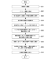
- FIG. 2 is a flowchart showing the operation of the sound measuring system 1 in the first embodiment of the present invention.
- the operation of the sound measuring system 1 shown in the flowchart of Fig. 2 is started, for example, when the event camera 20 receives an instruction to capture an image of a subject.
- the event camera 20 captures an image of a subject (step S01).
- the event camera 20 generates event information that indicates the luminance change for each pixel in the image of the subject, and outputs the generated event information to the sound measuring device 10 (step S02).
- the vibration information acquisition unit 11 of the acoustic measurement device 10 observes the vibration of the subject caused by the sound based on the acquired event information (step S03).
- the vibration information acquisition unit 11 outputs vibration information indicating the observed vibration to the vibration direction analysis unit 12.
- the vibration direction analysis unit 12 analyzes the vibration direction of the subject by calculating the optical flow for the acquired vibration information (step S04). Note that while general conventional technology can be used to calculate the optical flow, further improvement in measurement accuracy can be expected by calculating the optical flow assuming vibration.
- the vibration direction analysis unit 12 outputs information indicating the analyzed vibration direction of the subject (hereinafter referred to as "vibration direction information") and the vibration information to the continuous signal generation unit 13.
- the continuous signal generating unit 13 generates a pulse signal in response to the occurrence of an event at a certain time in a single pixel, taking into account the vibration direction (step S05).
- the continuous signal generating unit 13 generates a continuous signal by adding up the generated pulse signals in the time direction (step S06).
- the continuous signal generating unit 13 outputs the generated continuous signal to the signal analyzing unit 14.
- the signal analysis unit 14 performs frequency analysis such as a short-time Fourier transform on the acquired continuous signal.
- the signal analysis unit 14 estimates the frequency contained in the vibration and the phase of the frequency signal (step S07).
- the signal analysis unit 14 also estimates the intensity of each frequency signal by determining the amplitude based on the optical flow calculated by the vibration direction analysis unit 12 (step S08).
- the signal analysis unit 14 measures the sound by adding up each frequency signal taking into account the estimated intensity and phase (step S09).
- the signal analysis unit 14 outputs the measured acoustic information to an external device (step S10). This completes the operation of the acoustic measurement system 1 shown in the flowchart of FIG. 2.
- the acoustic measurement system 1 in the first embodiment generates event information using the event camera 20 and observes vibrations of a subject caused by sound.
- the acoustic measurement system 1 analyzes the vibration direction of the subject based on the vibration information.
- the acoustic measurement system 1 generates a continuous signal from the vibration information, taking into account the vibration direction.
- the acoustic measurement system 1 measures sound by performing signal analysis on the generated continuous signal.
- the acoustic measurement system 1 in the first embodiment uses the event camera 20, so there is no need for an expensive high-speed camera, and costs such as equipment costs and maintenance costs can be reduced.
- the acoustic measurement system 1 in the first embodiment uses the event camera 20, it can ensure a maximum sampling rate of 1 MHz, and can obtain extremely high time resolution compared to high-speed cameras. This value is sufficient even when compared to the typical sampling rate of acoustic signals, which is 44.1 KHz.
- the event camera 20 provides excellent data efficiency because it outputs asynchronously at each pixel. For these reasons, the acoustic measurement system 1 in the first embodiment is not limited in the range of sounds that can be measured.
- the acoustic measurement system 1 in the first embodiment does not need to perform time-intensive processing such as wavelet transform on a large amount of image data, so it is possible to suppress an increase in the amount of time required for calculation. As a result, the acoustic measurement system 1 in the first embodiment also makes it easy to perform measurements in real time.
- the acoustic measurement system 1 in the first embodiment of the present invention can achieve high-resolution, high-speed optical acoustic measurement while keeping costs down.
- Fig. 3 is a block diagram showing the functional configuration of the acoustic measurement system 1a in the second embodiment of the present invention.
- the acoustic measurement system 1a includes an acoustic measurement device 10a and an event camera 20.
- the acoustic measurement device 10a includes a vibration information acquisition unit 11, a vibration direction analysis unit 12, a continuous signal generation unit 13a, and a signal analysis unit 14a.
- the vibration direction analysis unit 12, the continuous signal generation unit 13a, and the signal analysis unit 14a function as an acoustic analysis unit.
- the configuration of the event camera 20 shown in FIG. 3 is similar to the configuration of the event camera 20 of the acoustic measurement system 1 in the first embodiment shown in FIG. 1 described above, and therefore a description thereof will be omitted.
- the configurations of the vibration information acquisition unit 11 and vibration direction analysis unit 12 of the acoustic measurement device 10 shown in FIG. 3 are similar to the configurations of the vibration information acquisition unit 11 and vibration direction analysis unit 12 of the acoustic measurement device 10 in the acoustic measurement system 1 in the first embodiment shown in FIG. 1 described above, and therefore a description thereof will be omitted.
- the continuous signal generating unit 13a acquires the vibration direction information and vibration information output from the vibration direction analyzing unit 12.
- the continuous signal generating unit 13a generates a continuous signal from the acquired vibration information, taking into account the vibration direction based on the acquired vibration direction information.
- the continuous signal generating unit 13a calculates the number of events occurring for each section in a single pixel, in accordance with the sampling rate of the sound being measured, while taking into account the vibration direction.
- the continuous signal generating unit 13a generates a continuous signal by integrating the number of events occurring calculated for each section across all sections. Note that calculations can also be performed for multiple pixels in order to increase the number of samples.
- the continuous signal generating unit 13a outputs the generated continuous signal to the signal analyzing unit 14a.
- the signal analysis unit 14a acquires the continuous signal output from the continuous signal generation unit 13a.
- the signal analysis unit 14a measures the sound by performing signal analysis on the acquired continuous signal.
- the signal analysis unit 14a performs frequency analysis such as a short-time Fourier transform on the acquired continuous signal.
- the signal analysis unit 14a estimates the frequency contained in the vibration and the phase of the frequency signal. Furthermore, based on the assumption that a large amplitude indicates a large number of event occurrences, the signal analysis unit 14a estimates the intensity obtained from the generated continuous signal as the intensity of the frequency signal.
- the signal analysis unit 14a measures the sound by adding up the frequency signals taking into account the estimated intensity and phase.
- the signal analysis unit 14a outputs measured acoustic information indicating the measured acoustic sound to an external device.
- the external device here is, for example, a storage device that stores the measured acoustic information, or a speaker that outputs sound based on the measured acoustic information.
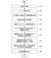
- FIG. 4 is a flowchart showing the operation of the sound measuring system 1a according to the second embodiment of the present invention.
- the operation of the sound measuring system 1a shown in the flowchart of Fig. 4 is started, for example, when the event camera 20 receives an instruction to capture an image of a subject.
- step S11 to step S14 shown in FIG. 4 the operation of the acoustic measurement system 1a from step S11 to step S14 shown in FIG. 4 is similar to the operation of the acoustic measurement system 1 in the first embodiment from step S01 to step S04 shown in FIG. 2 described above, and therefore will not be described.
- the continuous signal generating unit 13a calculates the number of occurrences of events for each section in accordance with the sampling rate of the sound being measured, taking into account the vibration direction, for a single pixel (step S15).
- the continuous signal generating unit 13a generates a continuous signal by integrating the number of occurrences of events calculated for each section across all sections (step S16).
- the continuous signal generating unit 13a outputs the generated continuous signal to the signal analyzing unit 14a.
- the signal analysis unit 14a performs frequency analysis such as a short-time Fourier transform on the acquired continuous signal.
- the signal analysis unit 14a estimates the frequency contained in the vibration and the phase of the frequency signal (step S17).
- the signal analysis unit 14a also estimates the intensity obtained from the generated continuous signal as the intensity of the frequency signal (step S18).
- the signal analysis unit 14a measures the sound by adding up the frequency signals taking into account the estimated intensity and phase (step S19).
- the signal analysis unit 14a outputs the measured acoustic information to an external device (step S20). This completes the operation of the acoustic measurement system 1a shown in the flowchart of FIG. 4.
- the acoustic measurement system 1a in the second embodiment generates event information using the event camera 20 and observes vibrations of the subject caused by sound.
- the acoustic measurement system 1a analyzes the vibration direction of the subject based on the vibration information.
- the acoustic measurement system 1a generates a continuous signal from the vibration information, taking into account the vibration direction.
- the acoustic measurement system 1a measures the sound by performing signal analysis on the generated continuous signal.
- the acoustic measurement system 1a in the second embodiment uses the event camera 20, so there is no need for an expensive high-speed camera, and costs such as equipment costs and maintenance costs can be reduced.
- the acoustic measurement system 1a in the second embodiment uses the event camera 20, it can ensure a maximum sampling rate of 1 MHz, and can obtain extremely high time resolution compared to high-speed cameras. This value is sufficient even when compared to the typical sampling rate of acoustic signals, which is 44.1 KHz. Furthermore, the event camera 20 provides asynchronous output for each pixel, resulting in excellent data efficiency. For these reasons, the acoustic measurement system 1a in the second embodiment is not limited in the range of sounds that can be measured.
- the acoustic measurement system 1a in the second embodiment of the present invention can achieve high-resolution, high-speed optical acoustic measurement while keeping costs down.
- the acoustic measurement device includes an observation unit, an analysis unit, a signal generation unit, and a measurement unit.
- the acoustic measurement device is acoustic measurement device 10, 10a in the embodiment
- the observation unit is vibration information acquisition unit 11 in the embodiment
- the analysis unit is vibration direction analysis unit 12 in the embodiment
- the signal generation unit is continuous signal generation unit 13, 13a in the embodiment
- the measurement unit is signal analysis unit 14, 14a in the embodiment.
- the analysis unit may analyze the vibration direction by calculating the optical flow for the vibration information.
- the above-mentioned program may be a program for realizing part of the above-mentioned function, or may be a program that can realize the above-mentioned function in combination with a program already recorded in the computer system, or may be a program that is realized using a programmable logic device such as an FPGA (Field Programmable Gate Array).
- a programmable logic device such as an FPGA (Field Programmable Gate Array).
Landscapes
- Physics & Mathematics (AREA)
- Engineering & Computer Science (AREA)
- Acoustics & Sound (AREA)
- Multimedia (AREA)
- Measurement Of Mechanical Vibrations Or Ultrasonic Waves (AREA)
Abstract
La présente invention concerne un dispositif de mesure acoustique comprenant : une unité d'observation qui observe des vibrations induites par le son d'un sujet sur la base d'informations d'événement indiquant des changements de luminance dans des pixels individuels d'une image dans laquelle le sujet est capturé, et délivre en sortie des informations de vibration indiquant les vibrations observées ; une unité d'analyse qui analyse la direction de vibration du sujet sur la base des informations de vibration, et délivre en sortie des informations de direction de vibration indiquant la direction de vibration analysée ; une unité de génération de signal qui génère un signal continu à partir des informations de vibration, en prenant en compte la direction de vibration indiquée par les informations de direction de vibration, et délivre en sortie le signal continu généré ; et une unité de mesure qui mesure des propriétés acoustiques par la réalisation d'une analyse de signal sur le signal continu.
Priority Applications (1)
| Application Number | Priority Date | Filing Date | Title |
|---|---|---|---|
| PCT/JP2023/030122 WO2025041256A1 (fr) | 2023-08-22 | 2023-08-22 | Dispositif de mesure acoustique, système de mesure acoustique, procédé de mesure acoustique et programme |
Applications Claiming Priority (1)
| Application Number | Priority Date | Filing Date | Title |
|---|---|---|---|
| PCT/JP2023/030122 WO2025041256A1 (fr) | 2023-08-22 | 2023-08-22 | Dispositif de mesure acoustique, système de mesure acoustique, procédé de mesure acoustique et programme |
Publications (1)
| Publication Number | Publication Date |
|---|---|
| WO2025041256A1 true WO2025041256A1 (fr) | 2025-02-27 |
Family
ID=94731987
Family Applications (1)
| Application Number | Title | Priority Date | Filing Date |
|---|---|---|---|
| PCT/JP2023/030122 Pending WO2025041256A1 (fr) | 2023-08-22 | 2023-08-22 | Dispositif de mesure acoustique, système de mesure acoustique, procédé de mesure acoustique et programme |
Country Status (1)
| Country | Link |
|---|---|
| WO (1) | WO2025041256A1 (fr) |
Citations (1)
| Publication number | Priority date | Publication date | Assignee | Title |
|---|---|---|---|---|
| WO2022190622A1 (fr) * | 2021-03-08 | 2022-09-15 | ソニーセミコンダクタソリューションズ株式会社 | Dispositif de traitement d'informations, procédé de traitement d'informations et programme |
-
2023
- 2023-08-22 WO PCT/JP2023/030122 patent/WO2025041256A1/fr active Pending
Patent Citations (1)
| Publication number | Priority date | Publication date | Assignee | Title |
|---|---|---|---|---|
| WO2022190622A1 (fr) * | 2021-03-08 | 2022-09-15 | ソニーセミコンダクタソリューションズ株式会社 | Dispositif de traitement d'informations, procédé de traitement d'informations et programme |
Similar Documents
| Publication | Publication Date | Title |
|---|---|---|
| Davis et al. | The visual microphone: Passive recovery of sound from video | |
| US10129658B2 (en) | Method and apparatus for recovering audio signals from images | |
| CN110068388A (zh) | 一种基于视觉和盲源分离的振动检测方法 | |
| CN111277833B (zh) | 一种基于多通带滤波器的多目标微小振动视频放大方法 | |
| CN108414240B (zh) | 一种检测机器异常振动的方法与装置 | |
| CN103794221B (zh) | 信号处理装置和方法 | |
| JP2019062527A (ja) | エッジ演算を用いる多カメラシステムでのリアルタイムの対象再識別 | |
| WO2021036662A1 (fr) | Procédé et dispositif de traitement de signal, et produit associé | |
| US12413805B2 (en) | Systems and methods for high-rate composite video acquisition | |
| WO2025041256A1 (fr) | Dispositif de mesure acoustique, système de mesure acoustique, procédé de mesure acoustique et programme | |
| US12425741B2 (en) | Systems and methods for motion detection, quantification, and/or measurement with exposure correction in video-based time-series signals | |
| CN108964998B (zh) | 一种网络实体行为奇异性检测方法及装置 | |
| JP5534870B2 (ja) | 音源推定用画像の作成装置 | |
| US20070269112A1 (en) | Image processing apparatus and image processing program | |
| WO2023105548A1 (fr) | Dispositif de classification, procédé de classification et programme | |
| JPWO2023105548A5 (fr) | ||
| Kotus et al. | Application of fast cameras to string vibrations recording | |
| Orak et al. | Monitoring cantilever beam with a vision-based algorithm and smartphone | |
| KR101438073B1 (ko) | 이미지 처리를 통한 객체의 동적 특성 분석 장치 및 이를 위한 방법 | |
| US20250211934A1 (en) | Computer system, method, and program | |
| US12445727B2 (en) | Acoustic eavesdropping using a smartphone camera | |
| Samuelson et al. | Visio-Acoustic Data Fusion for Structural Health Monitoring Applications | |
| JP2024165819A (ja) | 情報処理システム、情報処理方法及びプログラム | |
| JP3967163B2 (ja) | 画像生成方法および装置、画像処理方法および装置並びにプログラム | |
| US12607541B2 (en) | Robust predictive maintenance method for machinery using measured vibration data and estimated sound data |
Legal Events
| Date | Code | Title | Description |
|---|---|---|---|
| 121 | Ep: the epo has been informed by wipo that ep was designated in this application |
Ref document number: 23949717 Country of ref document: EP Kind code of ref document: A1 |
|
| ENP | Entry into the national phase |
Ref document number: 2025541209 Country of ref document: JP Kind code of ref document: A |
|
| WWE | Wipo information: entry into national phase |
Ref document number: 2025541209 Country of ref document: JP |