WO2025041249A1 - 分析装置および分析方法 - Google Patents
分析装置および分析方法 Download PDFInfo
- Publication number
- WO2025041249A1 WO2025041249A1 PCT/JP2023/030094 JP2023030094W WO2025041249A1 WO 2025041249 A1 WO2025041249 A1 WO 2025041249A1 JP 2023030094 W JP2023030094 W JP 2023030094W WO 2025041249 A1 WO2025041249 A1 WO 2025041249A1
- Authority
- WO
- WIPO (PCT)
- Prior art keywords
- flow information
- analysis
- failure
- information
- router
- Prior art date
- Legal status (The legal status is an assumption and is not a legal conclusion. Google has not performed a legal analysis and makes no representation as to the accuracy of the status listed.)
- Pending
Links
Images


Classifications
-
- H—ELECTRICITY
- H04—ELECTRIC COMMUNICATION TECHNIQUE
- H04L—TRANSMISSION OF DIGITAL INFORMATION, e.g. TELEGRAPHIC COMMUNICATION
- H04L41/00—Arrangements for maintenance, administration or management of data switching networks, e.g. of packet switching networks
- H04L41/06—Management of faults, events, alarms or notifications
- H04L41/0631—Management of faults, events, alarms or notifications using root cause analysis; using analysis of correlation between notifications, alarms or events based on decision criteria, e.g. hierarchy, tree or time analysis
Definitions
- the present invention was made in consideration of the above, and aims to accurately grasp the condition of the disability.
- the analysis device is characterized by having a collection unit that collects flow information representing the contents of traffic circulating through each edge router from a core router that aggregates edge routers, and an analysis unit that analyzes the failure situation using the collected flow information and information representing the connection relationships between devices in the network.
- FIG. 1 is a diagram for explaining an overview of an analysis device according to the present embodiment.
- a carrier network of a telecommunications carrier is composed of forwarding devices such as an edge router E and a core router C for forwarding IP packets, and transmission devices for connecting geographically separated sections.
- the end user's home transfer device is connected to the network via an edge router E.
- the edge router E is also aggregated into a core router C, which is then aggregated into a transmission device.
- a transmission section there may be multiple transmission devices between the transmission devices at both ends that have transponders.
- multiple optical paths with different wavelengths are accommodated between the transmission devices using wavelength division multiplexing, and multiple transfer devices are connected to the transmission device.
- edge routers E In such a carrier network, because there are many edge routers E installed, if a high-load failure occurs, such as multiple simultaneous restarts of edge routers E, there is a risk that it will be impossible to obtain alarm information and it will be impossible to distinguish between devices that have recovered and devices that have not. In addition, there is no way to know which users were communicating using each transfer device when the failure occurred, making it difficult to accurately determine the number of users who are actually unable to communicate or who are impaired.
- the analysis device of this embodiment therefore analyzes the fault situation using flow information 14a collected from a core router C that aggregates multiple edge routers E, and connection relationship information 14b that represents the connection relationships between devices within the network.
- flow information 14a is information that indicates the contents of the traffic that has circulated through edge router E.
- flow information 14a has undergone a format conversion process that enables packets inside the capsule of encapsulated packets to be extracted and analyzed, and is information that reveals the contents of the traffic circulating through edge router E.
- flow information 14a includes the source IP address/destination IP address of the traffic, the source port number/destination port number, the input interface/output interface, the number of bytes of the flow information, the number of packets, etc.
- the analysis device then analyzes the state of the failure, for example, by a flow information visualization process that aggregates and visualizes the amount of inflow and outflow traffic for each edge router E.
- the analysis device performs an affected user count determination process that identifies the end users or VPN groups affected by the failure, using flow information at the time of the failure collected by a core router C connected to the network device where the failure occurred. In this way, the analysis device makes it possible to accurately determine the state of the failure.
- FIG. 2 is a schematic diagram illustrating a schematic configuration of an analysis device of this embodiment.
- an analysis device 10 of this embodiment is realized by a general-purpose computer such as a personal computer, and includes an input unit 11, an output unit 12, a communication control unit 13, a storage unit 14, and a control unit 15.
- the input unit 11 is realized using input devices such as a keyboard and a mouse, and inputs various instruction information such as starting processing to the control unit 15 in response to input operations by an operator.
- the output unit 12 is realized by a display device such as a liquid crystal display, a printing device such as a printer, etc. For example, the output unit 12 displays the results of the analysis processing described below.
- the communication control unit 13 is realized by a NIC (Network Interface Card) or the like, and controls communication between the control unit 15 and external devices via telecommunication lines such as a LAN (Local Area Network) or the Internet.
- NIC Network Interface Card
- the communication control unit 13 controls communication between the control unit 15 and a core router C, other network devices, and a management device that manages various information.
- the flow information 14a is flow information of traffic flowing through each edge router E, collected by the collection unit 15a (described later) from the core router C that aggregates the edge routers E.
- the flow information 14a is information collected from the core router C, and processed (format conversion processing) to extract packets inside the capsule of encapsulated packets so that they can be analyzed, and is information that reveals the contents of the traffic flowing through the edge routers E subordinate to the core router C.
- the flow information 14a includes, for example, the source IP address/destination IP address of the traffic, the source port number/destination port number, the input interface/output interface, the number of bytes of the flow information, the number of packets, etc.
- the control unit 15 is realized using a CPU (Central Processing Unit) or the like, and executes a processing program stored in memory. As a result, the control unit 15 functions as a collection unit 15a and an analysis unit 15b, as exemplified in FIG. 2, and executes analysis processing. Note that these functional units may each be implemented in different hardware. The control unit 15 may also include other functional units.
- CPU Central Processing Unit
- the analysis unit 15b analyzes the failure situation using the collected flow information 14a and connection relationship information 14b that indicates the connection relationships between devices in the network.
- edge router E1 if the traffic volume at the current time t2 remains greater than a predetermined threshold (e.g., 70%) of the traffic volume immediately before the failure time t1 for a predetermined period of time, it is possible to determine that the failure has been recovered from or that there is no impact.
- a predetermined threshold e.g. 70%
- the analysis unit 15b can analyze whether the edge router E has recovered from a failure by aggregating the traffic volume of flow information for each edge router E.
- the analysis unit 15b performs a process to grasp the number of affected users.
- the analysis unit 15b first acquires flow information collected from the core router C connected to the network device in which the failure occurred from the collected flow information 14a. Then, the analysis unit 15b identifies the end users included in the flow information as users affected by the failure, as the status of the failure.
- Figs. 5 and 6 show an example of the process of grasping the number of affected users.
- the analysis unit 15b accepts an input specifying the network device in which a failure has occurred via the input unit 11 or the communication control unit 13, as shown in Fig. 5 (1).
- the analysis unit 15b refers to the connection relationship information 14b, as shown in Fig. 5 (2), and identifies all core routers C connected to the specified network device.
- the analysis unit 15b refers to the connection relationship information 14b, and based on information about a certain transponder, its opposing transponder, and the transmission devices that exist between them, identifies all routes that include the transmission device where the failure occurred, and identifies all transponders included in the routes.
- the analysis unit 15b also refers to the connection relationship information 14b and identifies the core router C that is connected to the transponder.
- the analysis unit 15b refers to the connection relationship information 14b and identifies the core router C connected to the transponder where the failure occurred.
- the analysis unit 15b obtains from the flow information 14a the flow information collected from the identified core router C around the time when the failure occurred.
- the analysis unit 15b also outputs the analysis results (step S3). For example, when the analysis unit 15b has performed flow information visualization processing, it tallies the inflow/outflow traffic volume of flow information for each edge router E, visualizes the tallied results, and outputs them to the output unit 12. Alternatively, when the analysis unit 15b has performed affected user count grasping processing, it outputs to the output unit 12 a list of at least either end-user home transfer devices or VPN groups that were actually communicating around the time the failure occurred and were affected by the failure. This completes the series of analysis processes.
- the analysis unit 15b acquires flow information collected from the core router C connected to the device where the failure occurred from the collected flow information 14a, and identifies the end users included in the flow information as users affected by the failure as the status of the failure.
- the analysis device 10 makes it possible to accurately identify the status of the failure.
- a program in which the processing executed by the analysis device 10 according to the above embodiment is written in a language executable by a computer can also be created.
- the analysis device 10 can be implemented by installing an analysis program that executes the above analysis processing as package software or online software on a desired computer.
- the information processing device can function as the analysis device 10 by executing the above analysis program on an information processing device.
- the information processing device referred to here includes general-purpose computers such as server computers and desktop or notebook personal computers.
- the information processing device also includes mobile communication terminals such as smartphones, mobile phones, and PHS (Personal Handyphone System), as well as slate terminals such as PDAs (Personal Digital Assistants).
- the functions of the analysis device 10 may also be implemented on a cloud server.
- the memory 1010 includes a ROM (Read Only Memory) 1011 and a RAM 1012.
- the ROM 1011 stores a boot program such as a BIOS (Basic Input Output System).
- BIOS Basic Input Output System
- the hard disk drive interface 1030 is connected to a hard disk drive 1031.
- the disk drive interface 1040 is connected to a disk drive 1041.
- a removable storage medium such as a magnetic disk or optical disk is inserted into the disk drive 1041.
- the serial port interface 1050 is connected to a mouse 1051 and a keyboard 1052, for example.
- the video adapter 1060 is connected to a display 1061, for example.
- the hard disk drive 1031 stores, for example, an OS (Operating System) 1091, application programs 1092, program modules 1093, and program data 1094. Each piece of information described in the above embodiment is stored, for example, in the hard disk drive 1031 or memory 1010.
- OS Operating System
- the analysis program is stored in the hard disk drive 1031, for example, as a program module 1093 in which instructions to be executed by the computer 1000 are written.
- the program module 1093 in which each process executed by the analysis device 10 described in the above embodiment is written is stored in the hard disk drive 1031.
- data used for information processing by the analysis program is stored as program data 1094, for example, in the hard disk drive 1031.
- the CPU 1020 reads the program module 1093 and program data 1094 stored in the hard disk drive 1031 into the RAM 1012 as necessary, and executes each of the procedures described above.
- the program module 1093 and program data 1094 related to the analysis program are not limited to being stored in the hard disk drive 1031, but may be stored in a removable storage medium, for example, and read by the CPU 1020 via the disk drive 1041 or the like.
- the program module 1093 and program data 1094 related to the analysis program may be stored in another computer connected via a network, such as a LAN or WAN (Wide Area Network), and read by the CPU 1020 via the network interface 1070.
Landscapes
- Engineering & Computer Science (AREA)
- Computer Networks & Wireless Communication (AREA)
- Signal Processing (AREA)
- Data Exchanges In Wide-Area Networks (AREA)
Abstract
分析装置(10)において、収集部(15a)が、エッジルータを集約するコアルータ(C)から各エッジルータを流通したトラヒックの内容を表すフロー情報(14a)を収集する。分析部(15b)が、収集されたフロー情報(14a)と、ネットワーク内の装置間の接続関係を表す接続関係情報(14b)とを用いて、障害の状況を分析する。
Description
本発明は、分析装置および分析方法に関する。
通信事業者の大規模キャリア網では、多数の転送装置、伝送装置で構成されており、キャリア網の運用・監視においては、網を構成する各装置での障害発生状況や復旧状況や、障害の影響を受けたいわゆるり障ユーザの数の迅速な把握が求められている。
従来、あらかじめ指定した異常事象の発生や、装置の状態を示すメッセージを発出するsyslog、SNMP trapなどを用いて運用、監視を行っている(非特許文献1~3参照)。
"MIBとsyslogは何が違う?"、[online]、日経XTECK、[2023年7月18日検索]、インターネット<URL:https://xtech.nikkei.com/it/atcl/column/17/011900625/011900009/>
"The Syslog Protocol"、[online]、RFC5424、[2023年7月18日検索]、インターネット<URL:https://datatracker.ietf.org/doc/html/rfc5424>
"A Simple Network Management Protocol (SNMP)"、 [online]、RFC1157、[2023年7月18日検索]、インターネット<URL:https://datatracker.ietf.org/doc/html/rfc1157>
しかしながら、従来技術によれば、障害の状況を正確に把握することが困難な場合がある。例えば、キャリア網の中でも装置台数の多いエッジルータが、同時多発的に再起動を繰り返し起こすような高負荷障害等が起こった場合、警報の取得ができず回復したか否かの影響の把握が難しかった。また、装置毎の静的な収容ユーザ数情報以外に、障害時に実際に通信ができなかったり障ユーザ数の正確な把握が難しかった。
本発明は、上記に鑑みてなされたものであって、障害の状況を正確に把握することを目的とする。
上述した課題を解決し、目的を達成するために、本発明に係る分析装置は、エッジルータを集約するコアルータから各エッジルータを流通したトラヒックの内容を表すフロー情報を収集する収集部と、収集された前記フロー情報と、ネットワーク内の装置間の接続関係を表す情報とを用いて、障害の状況を分析する分析部と、を有することを特徴とする。
本発明によれば、障害の状況を正確に把握することが可能となる。
以下、図面を参照して、本発明の一実施形態を詳細に説明する。なお、この実施形態により本発明が限定されるものではない。また、図面の記載において、同一部分には同一の符号を付して示している。
[分析装置の概要]
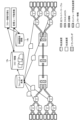
図1は、本実施形態の分析装置の概要を説明するための図である。通信事業者のキャリア網は、図1に例示するように、IPパケットを転送するエッジルータE、コアルータC等の転送装置と、地理的に離れた区間を接続する伝送装置とで構成される。
図1は、本実施形態の分析装置の概要を説明するための図である。通信事業者のキャリア網は、図1に例示するように、IPパケットを転送するエッジルータE、コアルータC等の転送装置と、地理的に離れた区間を接続する伝送装置とで構成される。
エンドユーザのユーザ宅転送装置はエッジルータEを介してネットワークに接続される。また、エッジルータEはコアルータCに集約され、コアルータCが伝送装置に集約される。伝送区間には、トランスポンダを有する両端の伝送装置の間に、複数台の伝送装置を有する場合がある。また、伝送装置間は波長分割多重方式を用いて波長の異なる複数の光パスが収容され、伝送装置には複数の転送装置が接続される。
このようなキャリア網において、エッジルータEは設置台数が多いため、例えば、エッジルータEで同時多発的に再起動を繰り返す等の高負荷障害が発生した場合に、警報情報を取得できずに回復した装置と未回復の装置との区別がつかないおそれがある。また、障害発生時に各転送装置を使って通信していたユーザを知る術がなく、実際に通信ができなかったり障ユーザの数を正確に把握することが難しい。
そこで、本実施形態の分析装置は、複数のエッジルータEを集約するコアルータCから収集したフロー情報14aと、ネットワーク内の装置間の接続関係を表す接続関係情報14bとを用いて、障害の状況を分析する。
ここで、フロー情報14aは、エッジルータEを流通したトラヒックの内容を表す情報である。具体的には、フロー情報14aは、カプセル化されたパケットのカプセル内部のパケットを取り出して分析可能とするフォーマット変換処理が行われ、エッジルータEを流通するトラヒックの中身がわかる情報である。例えば、フロー情報14aは、トラヒックの送信元IPアドレス/宛先IPアドレス、送信元ポート番号/宛先ポート番号、入力インタフェース/出力インタフェース、フロー情報のバイト数、パケット数等を含む。
また、接続関係情報14bは、トラヒックの経路のエッジルータEを特定可能な情報、送信元のエンドユーザ宅転送装置またはVPNグループを特定可能な情報、コアルータCの接続先のトランスポンダの情報、あるトランスポンダとこれに対向するトランスポンダと、両者の間に存在する伝送装置の情報、ある伝送装置に収容されるトランスポンダの情報等を含む。
そして、分析装置は、例えば、エッジルータEごとに流入トラヒック量と流出トラヒック量を集計して可視化するフロー情報可視化処理により、障害の状態を分析する。あるいは、分析装置は、障害が発生したネットワーク装置に接続されるコアルータCで収集された障害時のフロー情報を用いて、障害の影響を受けたエンドユーザあるいはVPNグループを特定する影響ユーザ数把握処理を行う。このように、分析装置によれば、障害の状況を正確に把握することが可能となる。
[分析装置の構成]
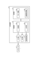
図2は、本実施形態の分析装置の概略構成を例示する模式図である。図2に例示するように、本実施形態の分析装置10は、パソコン等の汎用コンピュータで実現され、入力部11、出力部12、通信制御部13、記憶部14、および制御部15を備える。
図2は、本実施形態の分析装置の概略構成を例示する模式図である。図2に例示するように、本実施形態の分析装置10は、パソコン等の汎用コンピュータで実現され、入力部11、出力部12、通信制御部13、記憶部14、および制御部15を備える。
入力部11は、キーボードやマウス等の入力デバイスを用いて実現され、操作者による入力操作に対応して、制御部15に対して処理開始などの各種指示情報を入力する。出力部12は、液晶ディスプレイなどの表示装置、プリンター等の印刷装置等によって実現される。例えば、出力部12には、後述する分析処理の結果が表示される。
通信制御部13は、NIC(Network Interface Card)等で実現され、LAN(Local Area Network)やインターネットなどの電気通信回線を介した外部の装置と制御部15との通信を制御する。例えば、通信制御部13は、コアルータCや他のネットワーク装置や、各種情報を管理する管理装置等と制御部15との通信を制御する。
記憶部14は、RAM(Random Access Memory)、フラッシュメモリ(Flash Memory)等の半導体メモリ素子、または、ハードディスク、光ディスク等の記憶装置によって実現される。記憶部14には、分析装置10を動作させる処理プログラムや、処理プログラムの実行中に使用されるデータなどが予め記憶され、あるいは処理の都度一時的に記憶される。なお、記憶部14は、通信制御部13を介して制御部15と通信する構成でもよい。本実施形態において、記憶部14は、フロー情報14a、接続関係情報14bを有する。
フロー情報14aは、後述する収集部15aにより、エッジルータEを集約するコアルータCから収集された、各エッジルータEを流通したトラヒックのフロー情報である。具体的には、フロー情報14aは、コアルータCから収集され、カプセル化されたパケットのカプセル内部のパケットを取り出して分析可能とする処理(フォーマット変換処理)が行われた情報であり、コアルータCの配下のエッジルータEを流通するトラヒックの中身がわかる情報である。フロー情報14aは、例えば、トラヒックの送信元IPアドレス/宛先IPアドレス、送信元ポート番号/宛先ポート番号、入力インタフェース/出力インタフェース、フロー情報のバイト数、パケット数等を含む。
また、接続関係情報14bは、ネットワーク内の装置間の接続関係を表す情報であり、例えば、トラヒックの経路のエッジルータEを特定可能な情報、送信元のエンドユーザ宅転送装置またはVPNグループを特定可能な情報、コアルータCの接続先のトランスポンダの情報、あるトランスポンダとこれに対向するトランスポンダと、両者の間に存在する伝送装置の情報、ある伝送装置に収容されるトランスポンダの情報等を含む。接続関係情報14bは、例えば、各ネットワーク装置の設定情報等の各種情報を管理する管理装置等から予め収集され、記憶部14に記憶される。
制御部15は、CPU(Central Processing Unit)等を用いて実現され、メモリに記憶された処理プログラムを実行する。これにより、制御部15は、図2に例示するように、収集部15a、および分析部15bとして機能して、分析処理を実行する。なお、これらの機能部は、それぞれが異なるハードウェアに実装されてもよい。また、制御部15は、その他の機能部を備えてもよい。
収集部15aは、エッジルータEを集約するコアルータCから各エッジルータEを流通したトラヒックのフロー情報を収集する。具体的には、収集部15aは、通信制御部13を介してコアルータCからフロー情報を定期的に収集する。また、収集部15aは、収集したフロー情報に対し、カプセル化されたパケットのカプセル内部のパケットを取り出すフォーマット変換処理を行う。これにより、収集部15aは、コアルータCの配下のエッジルータEを流通するトラヒックの中身がわかるフロー情報を取り出して、記憶部14のフロー情報14aに格納する。なお、収集部15aは、取り出したフロー情報を記憶部14に格納せずに、以下の分析部15bに直接転送してもよい。
分析部15bは、収集されたフロー情報14aと、ネットワーク内の装置間の接続関係を表す接続関係情報14bとを用いて、障害の状況を分析する。
例えば、分析部15bは、フロー情報可視化処理を行う。すなわち、分析部15bは、収集されたフロー情報のトラヒック量をエッジルータEごとに集計することにより、障害の状況として、該エッジルータEの障害からの回復の有無を分析する。
ここで、図3~図6は、分析部の処理を説明するための図である。まず、図3および図4には、フロー情報可視化処理が例示されている。この場合に、分析部15bは、図3(1)に例示するように、フロー情報14aから、監視対象のエッジルータEを集約しているコアルータCのフロー情報のうち、例えば現在時刻から所定時間分遡ったフロー情報を取得する。そして、分析部15bは、図3(2)に例示するように、接続関係情報14bを参照し、フロー情報と当該フロー情報のトラヒックが経由したエッジルータEとを関連付ける情報を取得することにより、取得したフロー情報が経由したエッジルータEを特定する。
また、分析部15bは、エッジルータEごとに、フロー情報の流入/流出のトラヒック量を集計する。分析部15bは、例えば、図4に示すように、集計結果を可視化して出力部12に出力する。図4に示す例では、エッジルータE1、E2のそれぞれについて、キャリア網での障害発生時刻t1より前から現在時刻t2までのフロー情報のトラヒック量が可視化されている。
この場合に、エッジルータE1について例示するように、現在時刻t2のトラヒック量が、障害発生時刻t1の直前のトラヒック量に対して所定の閾値(例えば7割)以上である状態が所定時間継続している場合には、障害が復旧、あるいは影響なしと判定することが可能である。
一方、エッジルータE2について例示するように、現在時刻t2のトラヒック量が、障害発生時刻t1の直前のトラヒック量に対して所定の閾値(例えば7割)未満である状態が所定時間継続している場合には、障害が継続していると判定することが可能である。
このように、分析部15bがエッジルータEごとにフロー情報のトラヒック量を集計することにより、エッジルータEの障害からの回復の有無を分析することが可能である。
あるいは、分析部15bは、影響ユーザ数把握処理を行う。この場合には、まず、分析部15bは、収集されたフロー情報14aから、障害が発生したネットワーク装置と接続されたコアルータCから収集されたフロー情報を取得する。そして、分析部15bが、障害の状況として、フロー情報に含まれるエンドユーザを、障害の影響を受けたユーザとして特定する。
ここで、図5および図6には、影響ユーザ数把握処理が例示されている。この場合に、まず、分析部15bが、図5(1)に示すように、障害が発生したネットワーク装置を指定する入力を、入力部11あるいは通信制御部13を介して受け付ける。次に、分析部15bは、図5(2)に示すように、接続関係情報14bを参照し、指定されたネットワーク装置に接続されている全てのコアルータCを特定する。
例えば、障害が伝送装置で発生した場合に、分析部15bは、接続関係情報14bを参照し、あるトランスポンダとこれに対向するトランスポンダと、両者の間に存在する伝送装置の情報とをもとに、障害が発生した伝送装置を含む全ての経路を特定し、経路に含まれる全てのトランスポンダを特定する。また、分析部15bは、接続関係情報14bを参照し、トランスポンダに接続されるコアルータCを特定する。
なお、障害がトランスポンダで発生した場合には、図5(2)において、分析部15bは、接続関係情報14bを参照し、障害が発生したトランスポンダに接続されるコアルータCを特定する。
そして、分析部15bは、図5(3)に示すように、フロー情報14aから、障害発生時刻付近の時点に、特定されたコアルータCから収集されたフロー情報を取得する。
また、障害がコアルータCで発生した場合には、分析部15bは、図5(3)において、フロー情報14aから、障害発生時刻付近の時点に、障害が発生したコアルータCから収集されたフロー情報を取得する。
また、障害がエッジルータEで発生した場合には、分析部15bは、図5(3)において、フロー情報14aから、障害発生時刻付近の時点に、障害が発生したエッジルータEを経由したフロー情報を取得する。
次に、分析部15bは、図5(4)に示すように、接続関係情報14bを参照し、当該フロー情報を送受したエンドユーザ宅転送装置またはVPNグループの少なくともいずれかを特定し、一覧を作成する。
ここで、障害発生時刻付近の時点に通信をしていないユーザやVPNのフロー情報は存在しない。一方、対向するトランスポンダの配下のユーザ宅転送装置からの通信があれば、フロー情報が存在するため、障害の影響を受けたユーザまたはVPNとして特定可能である。
そこで、分析部15bは、図5(5)に示すように、作成したユーザ宅転送装置またはVPNグループの一覧を、影響ユーザまたは影響VPNとして、出力部12に提示する。
図6には、影響ユーザ数把握処理結果の提示画面が例示されている。図6に示す例は、トランスポンダT1の対向のトランスポンダの配下にH5、H6が存在し、障害発生時刻付近の時点で通信していたのは、H1、H2、H4、H6であった場合である。図6に示す例では、障害の状況として、障害の影響を受けたエンドユーザ宅転送装置の一覧とその総数、障害の影響を受けたVPNグループの一覧とその総数とが提示されている。
このように、分析部15bは、障害発生時刻付近の時点で実際に通信をしていて、障害の影響を受けたエンドユーザ宅転送装置またはVPNグループの少なくともいずれかを把握することが可能である。
[分析処理]
次に、図7を参照して、本実施形態に係る分析装置10による分析処理について説明する。図7は、分析処理手順を示すフローチャートである。図7のフローチャートは、例えば、ユーザが開始を指示する操作入力を行ったタイミングで開始される。
次に、図7を参照して、本実施形態に係る分析装置10による分析処理について説明する。図7は、分析処理手順を示すフローチャートである。図7のフローチャートは、例えば、ユーザが開始を指示する操作入力を行ったタイミングで開始される。
まず、収集部15aが、エッジルータEを集約するコアルータCから各エッジルータEを流通したトラヒックのフロー情報を収集する(ステップS1)。具体的には、収集部15aは、通信制御部13を介してコアルータCからフロー情報を定期的に収集する。また、収集部15aは、収集したフロー情報に対し、カプセル化されたパケットのカプセル内部のパケットを取り出すフォーマット変換処理を行う。これにより、収集部15aは、コアルータCの配下のエッジルータEを流通するトラヒックの中身がわかるフロー情報を取り出して、記憶部14のフロー情報14aに格納する。
次に、分析部15bが、収集されたフロー情報14aと、ネットワーク内の装置間の接続関係を表す接続関係情報14bとを用いて、障害の状況を分析する(ステップS2)。
例えば、分析部15bは、フロー情報可視化処理を行う。すなわち、分析部15bは、収集されたフロー情報のトラヒック量をエッジルータEごとに集計することにより、該エッジルータEの障害からの回復の有無を分析する。
あるいは、分析部15bは、影響ユーザ数把握処理を行う。この場合には、まず、分析部15bは、収集されたフロー情報から、障害が発生したネットワーク装置と接続されたコアルータCから収集されたフロー情報を取得する。そして、分析部15bが、フロー情報に含まれるエンドユーザを、障害の影響を受けたユーザとして特定する。
また、分析部15bは、分析結果を出力する(ステップS3)。例えば、分析部15bは、フロー情報可視化処理を行った場合には、エッジルータEごとに、フロー情報の流入/流出のトラヒック量を集計し、集計結果を可視化して出力部12に出力する。あるいは、分析部15bは、影響ユーザ数把握処理を行った場合には、障害発生時刻付近の時点で実際に通信をしていて、障害の影響を受けたエンドユーザ宅転送装置またはVPNグループの少なくともいずれかの一覧を出力部12に出力する。これにより、一連の分析処理が終了する。
[効果]
以上、説明したように、本実施形態の分析装置10において、収集部15aが、エッジルータEを集約するコアルータCから各エッジルータEを流通したトラヒックの内容を表すフロー情報14aを収集する。分析部15bが、収集されたフロー情報14aと、ネットワーク内の装置間の接続関係を表す接続関係情報14bとを用いて、障害の状況を分析する。
以上、説明したように、本実施形態の分析装置10において、収集部15aが、エッジルータEを集約するコアルータCから各エッジルータEを流通したトラヒックの内容を表すフロー情報14aを収集する。分析部15bが、収集されたフロー情報14aと、ネットワーク内の装置間の接続関係を表す接続関係情報14bとを用いて、障害の状況を分析する。
具体的には、分析部15bは、収集されたフロー情報14aのトラヒック量をエッジルータEごとに集計することにより、障害の状況として、該エッジルータEの障害からの回復の有無を分析する。
または、分析部15bは、収集されたフロー情報14aのうち、障害が発生した装置と接続されたコアルータCから収集されたフロー情報を取得し、障害の状況として、該フロー情報に含まれるエンドユーザを、障害の影響を受けたユーザとして特定する。
このように、エッジルータEごとにフロー情報のトラヒック量を集計することにより、エッジルータEの障害からの回復の有無を分析することが可能となる。あるいは、障害発生時刻付近の時点で実際に通信をしているフロー情報を用いることにより、障害の影響を受けたエンドユーザ宅転送装置またはVPNグループの少なくともいずれかを把握することが可能となる。このように、分析装置10によれば、障害の状況を正確に把握することが可能となる。
[プログラム]
上記実施形態に係る分析装置10が実行する処理をコンピュータが実行可能な言語で記述したプログラムを作成することもできる。一実施形態として、分析装置10は、パッケージソフトウェアやオンラインソフトウェアとして上記の分析処理を実行する分析プログラムを所望のコンピュータにインストールさせることによって実装できる。例えば、上記の分析プログラムを情報処理装置に実行させることにより、情報処理装置を分析装置10として機能させることができる。ここで言う情報処理装置には、サーバ用コンピュータ等の汎用コンピュータや、デスクトップ型またはノート型のパーソナルコンピュータが含まれる。また、その他にも、情報処理装置にはスマートフォン、携帯電話機やPHS(Personal Handyphone System)などの移動体通信端末、さらには、PDA(Personal Digital Assistant)などのスレート端末などがその範疇に含まれる。また、分析装置10の機能を、クラウドサーバに実装してもよい。
上記実施形態に係る分析装置10が実行する処理をコンピュータが実行可能な言語で記述したプログラムを作成することもできる。一実施形態として、分析装置10は、パッケージソフトウェアやオンラインソフトウェアとして上記の分析処理を実行する分析プログラムを所望のコンピュータにインストールさせることによって実装できる。例えば、上記の分析プログラムを情報処理装置に実行させることにより、情報処理装置を分析装置10として機能させることができる。ここで言う情報処理装置には、サーバ用コンピュータ等の汎用コンピュータや、デスクトップ型またはノート型のパーソナルコンピュータが含まれる。また、その他にも、情報処理装置にはスマートフォン、携帯電話機やPHS(Personal Handyphone System)などの移動体通信端末、さらには、PDA(Personal Digital Assistant)などのスレート端末などがその範疇に含まれる。また、分析装置10の機能を、クラウドサーバに実装してもよい。
図8は、分析プログラムを実行するコンピュータの一例を示す図である。コンピュータ1000は、例えば、メモリ1010と、CPU1020と、ハードディスクドライブインタフェース1030と、ディスクドライブインタフェース1040と、シリアルポートインタフェース1050と、ビデオアダプタ1060と、ネットワークインタフェース1070とを有する。これらの各部は、バス1080によって接続される。
メモリ1010は、ROM(Read Only Memory)1011およびRAM1012を含む。ROM1011は、例えば、BIOS(Basic Input Output System)等のブートプログラムを記憶する。ハードディスクドライブインタフェース1030は、ハードディスクドライブ1031に接続される。ディスクドライブインタフェース1040は、ディスクドライブ1041に接続される。ディスクドライブ1041には、例えば、磁気ディスクや光ディスク等の着脱可能な記憶媒体が挿入される。シリアルポートインタフェース1050には、例えば、マウス1051およびキーボード1052が接続される。ビデオアダプタ1060には、例えば、ディスプレイ1061が接続される。
ここで、ハードディスクドライブ1031は、例えば、OS(Operating System)1091、アプリケーションプログラム1092、プログラムモジュール1093およびプログラムデータ1094を記憶する。上記実施形態で説明した各情報は、例えばハードディスクドライブ1031やメモリ1010に記憶される。
また、分析プログラムは、例えば、コンピュータ1000によって実行される指令が記述されたプログラムモジュール1093として、ハードディスクドライブ1031に記憶される。具体的には、上記実施形態で説明した分析装置10が実行する各処理が記述されたプログラムモジュール1093が、ハードディスクドライブ1031に記憶される。
また、分析プログラムによる情報処理に用いられるデータは、プログラムデータ1094として、例えば、ハードディスクドライブ1031に記憶される。そして、CPU1020が、ハードディスクドライブ1031に記憶されたプログラムモジュール1093やプログラムデータ1094を必要に応じてRAM1012に読み出して、上述した各手順を実行する。
なお、分析プログラムに係るプログラムモジュール1093やプログラムデータ1094は、ハードディスクドライブ1031に記憶される場合に限られず、例えば、着脱可能な記憶媒体に記憶されて、ディスクドライブ1041等を介してCPU1020によって読み出されてもよい。あるいは、分析プログラムに係るプログラムモジュール1093やプログラムデータ1094は、LANやWAN(Wide Area Network)等のネットワークを介して接続された他のコンピュータに記憶され、ネットワークインタフェース1070を介してCPU1020によって読み出されてもよい。
以上、本発明者によってなされた発明を適用した実施形態について説明したが、本実施形態による本発明の開示の一部をなす記述および図面により本発明は限定されることはない。すなわち、本実施形態に基づいて当業者等によりなされる他の実施形態、実施例および運用技術等は全て本発明の範疇に含まれる。
10 分析装置
11 入力部
12 出力部
13 通信制御部
14 記憶部
14a フロー情報
14b 接続関係情報
15 制御部
15a 収集部
15b 分析部
C コアルータ
E エッジルータ
11 入力部
12 出力部
13 通信制御部
14 記憶部
14a フロー情報
14b 接続関係情報
15 制御部
15a 収集部
15b 分析部
C コアルータ
E エッジルータ
Claims (4)
- エッジルータを集約するコアルータから各エッジルータを流通したトラヒックの内容を表すフロー情報を収集する収集部と、
収集された前記フロー情報と、ネットワーク内の装置間の接続関係を表す情報とを用いて、障害の状況を分析する分析部と、
を有することを特徴とする分析装置。 - 前記分析部は、収集された前記フロー情報のトラヒック量を前記エッジルータごとに集計することにより、前記障害の状況として、該エッジルータの障害からの回復の有無を分析することを特徴とする請求項1に記載の分析装置。
- 前記分析部は、収集された前記フロー情報のうち、障害が発生した装置と接続されたコアルータから収集されたフロー情報を取得し、前記障害の状況として、該フロー情報に含まれるエンドユーザを、障害の影響を受けたユーザとして特定することを特徴とする請求項1に記載の分析装置。
- 分析装置が実行する分析方法であって、
エッジルータを集約するコアルータから各エッジルータを流通したトラヒックの内容を表すフロー情報を収集する収集工程と、
収集された前記フロー情報と、ネットワーク内の装置間の接続関係を表す情報とを用いて、障害の状況を分析する分析工程と、
を含んだことを特徴とする分析方法。
Priority Applications (1)
| Application Number | Priority Date | Filing Date | Title |
|---|---|---|---|
| PCT/JP2023/030094 WO2025041249A1 (ja) | 2023-08-22 | 2023-08-22 | 分析装置および分析方法 |
Applications Claiming Priority (1)
| Application Number | Priority Date | Filing Date | Title |
|---|---|---|---|
| PCT/JP2023/030094 WO2025041249A1 (ja) | 2023-08-22 | 2023-08-22 | 分析装置および分析方法 |
Publications (1)
| Publication Number | Publication Date |
|---|---|
| WO2025041249A1 true WO2025041249A1 (ja) | 2025-02-27 |
Family
ID=94731827
Family Applications (1)
| Application Number | Title | Priority Date | Filing Date |
|---|---|---|---|
| PCT/JP2023/030094 Pending WO2025041249A1 (ja) | 2023-08-22 | 2023-08-22 | 分析装置および分析方法 |
Country Status (1)
| Country | Link |
|---|---|
| WO (1) | WO2025041249A1 (ja) |
Citations (2)
| Publication number | Priority date | Publication date | Assignee | Title |
|---|---|---|---|---|
| JP2014220645A (ja) * | 2013-05-08 | 2014-11-20 | 富士通株式会社 | 障害判定プログラム、装置、システム、及び方法 |
| JP2020031410A (ja) * | 2018-08-24 | 2020-02-27 | 日本電信電話株式会社 | 分析システム及び分析方法 |
-
2023
- 2023-08-22 WO PCT/JP2023/030094 patent/WO2025041249A1/ja active Pending
Patent Citations (2)
| Publication number | Priority date | Publication date | Assignee | Title |
|---|---|---|---|---|
| JP2014220645A (ja) * | 2013-05-08 | 2014-11-20 | 富士通株式会社 | 障害判定プログラム、装置、システム、及び方法 |
| JP2020031410A (ja) * | 2018-08-24 | 2020-02-27 | 日本電信電話株式会社 | 分析システム及び分析方法 |
Non-Patent Citations (1)
| Title |
|---|
| KOIKE, OSAMU; HONMA, YASUSHI; OIMATSU, TOSHIO: "A study of the traffic collection system and management of MPLS network", IEICE TECHNICAL REPORT, IEICE, JP, vol. 104, no. 36, 7 May 2004 (2004-05-07), JP, pages 35 - 40, XP009561755, ISSN: 0913-5685 * |
Similar Documents
| Publication | Publication Date | Title |
|---|---|---|
| CN114884773B (zh) | 用于在覆盖网络中确定数据流路径的系统和方法 | |
| US9374278B2 (en) | Graphic user interface based network management system to define and execute troubleshooting procedure | |
| US20210258239A1 (en) | Network health data aggregation service | |
| US20210119890A1 (en) | Visualization of network health information | |
| EP3706390B1 (en) | Interactive hierarchical network chord diagram for application dependency mapping | |
| US10243820B2 (en) | Filtering network health information based on customer impact | |
| EP1742416B1 (en) | Method, computer readable medium and system for analyzing and management of application traffic on networks | |
| US10911263B2 (en) | Programmatic interfaces for network health information | |
| JP4774357B2 (ja) | 統計情報収集システム及び統計情報収集装置 | |
| US10469326B1 (en) | Discovering a computer network topology for an executing application | |
| US20160072688A1 (en) | Fault monitoring in multi-domain networks | |
| EP3364627B1 (en) | Adaptive session intelligence extender | |
| CN117955715A (zh) | 用于下一代防火墙的自动检测方法及装置 | |
| WO2025041249A1 (ja) | 分析装置および分析方法 | |
| EP4557680A1 (en) | Network monitoring system and method including software agents | |
| US20250097133A1 (en) | System and method for determining health status of nodes | |
| KR101829881B1 (ko) | 플로우 관제 시스템, 컨트롤러 및 장애 검출 방법 | |
| JP7794218B2 (ja) | ネットワーク情報可視化装置、ネットワーク情報可視化方法、ネットワーク情報可視化プログラム及びネットワーク情報可視化システム | |
| CN115567319A (zh) | 一种日志采集解析规则优化以及系统性能优化 | |
| US20250150366A1 (en) | Collecting device, collecting method, and collecting program | |
| US20260074972A1 (en) | Optimized Container-Based Network Intelligence | |
| JP4716720B2 (ja) | ネットワーク監視装置、ネットワーク監視方法、及びネットワーク監視プログラム | |
| WO2020040002A1 (ja) | 分析システム及び分析方法 | |
| US20240163191A1 (en) | Network scanner detection | |
| WO2025041343A1 (ja) | 抽出装置 |
Legal Events
| Date | Code | Title | Description |
|---|---|---|---|
| 121 | Ep: the epo has been informed by wipo that ep was designated in this application |
Ref document number: 23949710 Country of ref document: EP Kind code of ref document: A1 |
|
| ENP | Entry into the national phase |
Ref document number: 2025541203 Country of ref document: JP Kind code of ref document: A |
|
| WWE | Wipo information: entry into national phase |
Ref document number: 2025541203 Country of ref document: JP |
|
| NENP | Non-entry into the national phase |
Ref country code: DE |