WO2025041249A1 - Dispositif et procédé d'analyse - Google Patents
Dispositif et procédé d'analyse Download PDFInfo
- Publication number
- WO2025041249A1 WO2025041249A1 PCT/JP2023/030094 JP2023030094W WO2025041249A1 WO 2025041249 A1 WO2025041249 A1 WO 2025041249A1 JP 2023030094 W JP2023030094 W JP 2023030094W WO 2025041249 A1 WO2025041249 A1 WO 2025041249A1
- Authority
- WO
- WIPO (PCT)
- Prior art keywords
- flow information
- analysis
- failure
- information
- router
- Prior art date
- Legal status (The legal status is an assumption and is not a legal conclusion. Google has not performed a legal analysis and makes no representation as to the accuracy of the status listed.)
- Pending
Links
Images


Classifications
-
- H—ELECTRICITY
- H04—ELECTRIC COMMUNICATION TECHNIQUE
- H04L—TRANSMISSION OF DIGITAL INFORMATION, e.g. TELEGRAPHIC COMMUNICATION
- H04L41/00—Arrangements for maintenance, administration or management of data switching networks, e.g. of packet switching networks
- H04L41/06—Management of faults, events, alarms or notifications
- H04L41/0631—Management of faults, events, alarms or notifications using root cause analysis; using analysis of correlation between notifications, alarms or events based on decision criteria, e.g. hierarchy, tree or time analysis
Definitions
- the present invention was made in consideration of the above, and aims to accurately grasp the condition of the disability.
- the analysis device is characterized by having a collection unit that collects flow information representing the contents of traffic circulating through each edge router from a core router that aggregates edge routers, and an analysis unit that analyzes the failure situation using the collected flow information and information representing the connection relationships between devices in the network.
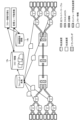
- FIG. 1 is a diagram for explaining an overview of an analysis device according to the present embodiment.
- a carrier network of a telecommunications carrier is composed of forwarding devices such as an edge router E and a core router C for forwarding IP packets, and transmission devices for connecting geographically separated sections.
- the end user's home transfer device is connected to the network via an edge router E.
- the edge router E is also aggregated into a core router C, which is then aggregated into a transmission device.
- a transmission section there may be multiple transmission devices between the transmission devices at both ends that have transponders.
- multiple optical paths with different wavelengths are accommodated between the transmission devices using wavelength division multiplexing, and multiple transfer devices are connected to the transmission device.
- edge routers E In such a carrier network, because there are many edge routers E installed, if a high-load failure occurs, such as multiple simultaneous restarts of edge routers E, there is a risk that it will be impossible to obtain alarm information and it will be impossible to distinguish between devices that have recovered and devices that have not. In addition, there is no way to know which users were communicating using each transfer device when the failure occurred, making it difficult to accurately determine the number of users who are actually unable to communicate or who are impaired.
- the analysis device of this embodiment therefore analyzes the fault situation using flow information 14a collected from a core router C that aggregates multiple edge routers E, and connection relationship information 14b that represents the connection relationships between devices within the network.
- flow information 14a is information that indicates the contents of the traffic that has circulated through edge router E.
- flow information 14a has undergone a format conversion process that enables packets inside the capsule of encapsulated packets to be extracted and analyzed, and is information that reveals the contents of the traffic circulating through edge router E.
- flow information 14a includes the source IP address/destination IP address of the traffic, the source port number/destination port number, the input interface/output interface, the number of bytes of the flow information, the number of packets, etc.
- the analysis device then analyzes the state of the failure, for example, by a flow information visualization process that aggregates and visualizes the amount of inflow and outflow traffic for each edge router E.
- the analysis device performs an affected user count determination process that identifies the end users or VPN groups affected by the failure, using flow information at the time of the failure collected by a core router C connected to the network device where the failure occurred. In this way, the analysis device makes it possible to accurately determine the state of the failure.
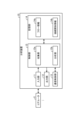
- FIG. 2 is a schematic diagram illustrating a schematic configuration of an analysis device of this embodiment.
- an analysis device 10 of this embodiment is realized by a general-purpose computer such as a personal computer, and includes an input unit 11, an output unit 12, a communication control unit 13, a storage unit 14, and a control unit 15.
- the input unit 11 is realized using input devices such as a keyboard and a mouse, and inputs various instruction information such as starting processing to the control unit 15 in response to input operations by an operator.
- the output unit 12 is realized by a display device such as a liquid crystal display, a printing device such as a printer, etc. For example, the output unit 12 displays the results of the analysis processing described below.
- the communication control unit 13 is realized by a NIC (Network Interface Card) or the like, and controls communication between the control unit 15 and external devices via telecommunication lines such as a LAN (Local Area Network) or the Internet.
- NIC Network Interface Card
- the communication control unit 13 controls communication between the control unit 15 and a core router C, other network devices, and a management device that manages various information.
- the flow information 14a is flow information of traffic flowing through each edge router E, collected by the collection unit 15a (described later) from the core router C that aggregates the edge routers E.
- the flow information 14a is information collected from the core router C, and processed (format conversion processing) to extract packets inside the capsule of encapsulated packets so that they can be analyzed, and is information that reveals the contents of the traffic flowing through the edge routers E subordinate to the core router C.
- the flow information 14a includes, for example, the source IP address/destination IP address of the traffic, the source port number/destination port number, the input interface/output interface, the number of bytes of the flow information, the number of packets, etc.
- the control unit 15 is realized using a CPU (Central Processing Unit) or the like, and executes a processing program stored in memory. As a result, the control unit 15 functions as a collection unit 15a and an analysis unit 15b, as exemplified in FIG. 2, and executes analysis processing. Note that these functional units may each be implemented in different hardware. The control unit 15 may also include other functional units.
- CPU Central Processing Unit
- the analysis unit 15b analyzes the failure situation using the collected flow information 14a and connection relationship information 14b that indicates the connection relationships between devices in the network.
- edge router E1 if the traffic volume at the current time t2 remains greater than a predetermined threshold (e.g., 70%) of the traffic volume immediately before the failure time t1 for a predetermined period of time, it is possible to determine that the failure has been recovered from or that there is no impact.
- a predetermined threshold e.g. 70%
- the analysis unit 15b can analyze whether the edge router E has recovered from a failure by aggregating the traffic volume of flow information for each edge router E.
- the analysis unit 15b performs a process to grasp the number of affected users.
- the analysis unit 15b first acquires flow information collected from the core router C connected to the network device in which the failure occurred from the collected flow information 14a. Then, the analysis unit 15b identifies the end users included in the flow information as users affected by the failure, as the status of the failure.
- Figs. 5 and 6 show an example of the process of grasping the number of affected users.
- the analysis unit 15b accepts an input specifying the network device in which a failure has occurred via the input unit 11 or the communication control unit 13, as shown in Fig. 5 (1).
- the analysis unit 15b refers to the connection relationship information 14b, as shown in Fig. 5 (2), and identifies all core routers C connected to the specified network device.
- the analysis unit 15b refers to the connection relationship information 14b, and based on information about a certain transponder, its opposing transponder, and the transmission devices that exist between them, identifies all routes that include the transmission device where the failure occurred, and identifies all transponders included in the routes.
- the analysis unit 15b also refers to the connection relationship information 14b and identifies the core router C that is connected to the transponder.
- the analysis unit 15b refers to the connection relationship information 14b and identifies the core router C connected to the transponder where the failure occurred.
- the analysis unit 15b obtains from the flow information 14a the flow information collected from the identified core router C around the time when the failure occurred.
- the analysis unit 15b also outputs the analysis results (step S3). For example, when the analysis unit 15b has performed flow information visualization processing, it tallies the inflow/outflow traffic volume of flow information for each edge router E, visualizes the tallied results, and outputs them to the output unit 12. Alternatively, when the analysis unit 15b has performed affected user count grasping processing, it outputs to the output unit 12 a list of at least either end-user home transfer devices or VPN groups that were actually communicating around the time the failure occurred and were affected by the failure. This completes the series of analysis processes.
- the analysis unit 15b acquires flow information collected from the core router C connected to the device where the failure occurred from the collected flow information 14a, and identifies the end users included in the flow information as users affected by the failure as the status of the failure.
- the analysis device 10 makes it possible to accurately identify the status of the failure.
- a program in which the processing executed by the analysis device 10 according to the above embodiment is written in a language executable by a computer can also be created.
- the analysis device 10 can be implemented by installing an analysis program that executes the above analysis processing as package software or online software on a desired computer.
- the information processing device can function as the analysis device 10 by executing the above analysis program on an information processing device.
- the information processing device referred to here includes general-purpose computers such as server computers and desktop or notebook personal computers.
- the information processing device also includes mobile communication terminals such as smartphones, mobile phones, and PHS (Personal Handyphone System), as well as slate terminals such as PDAs (Personal Digital Assistants).
- the functions of the analysis device 10 may also be implemented on a cloud server.
- the memory 1010 includes a ROM (Read Only Memory) 1011 and a RAM 1012.
- the ROM 1011 stores a boot program such as a BIOS (Basic Input Output System).
- BIOS Basic Input Output System
- the hard disk drive interface 1030 is connected to a hard disk drive 1031.
- the disk drive interface 1040 is connected to a disk drive 1041.
- a removable storage medium such as a magnetic disk or optical disk is inserted into the disk drive 1041.
- the serial port interface 1050 is connected to a mouse 1051 and a keyboard 1052, for example.
- the video adapter 1060 is connected to a display 1061, for example.
- the hard disk drive 1031 stores, for example, an OS (Operating System) 1091, application programs 1092, program modules 1093, and program data 1094. Each piece of information described in the above embodiment is stored, for example, in the hard disk drive 1031 or memory 1010.
- OS Operating System
- the analysis program is stored in the hard disk drive 1031, for example, as a program module 1093 in which instructions to be executed by the computer 1000 are written.
- the program module 1093 in which each process executed by the analysis device 10 described in the above embodiment is written is stored in the hard disk drive 1031.
- data used for information processing by the analysis program is stored as program data 1094, for example, in the hard disk drive 1031.
- the CPU 1020 reads the program module 1093 and program data 1094 stored in the hard disk drive 1031 into the RAM 1012 as necessary, and executes each of the procedures described above.
- the program module 1093 and program data 1094 related to the analysis program are not limited to being stored in the hard disk drive 1031, but may be stored in a removable storage medium, for example, and read by the CPU 1020 via the disk drive 1041 or the like.
- the program module 1093 and program data 1094 related to the analysis program may be stored in another computer connected via a network, such as a LAN or WAN (Wide Area Network), and read by the CPU 1020 via the network interface 1070.
Landscapes
- Engineering & Computer Science (AREA)
- Computer Networks & Wireless Communication (AREA)
- Signal Processing (AREA)
- Data Exchanges In Wide-Area Networks (AREA)
Abstract
L'invention concerne un dispositif d'analyse (10) dans lequel une unité de collecte (15a) collecte des informations de flux (14a) indiquant le contenu de trafic qui a traversé chaque routeur périphérique à partir d'un routeur central (C) qui intègre les routeurs périphériques. Une unité d'analyse (15b) analyse un état de défaillance en utilisant les informations de flux (14a) collectées et des informations de relation de connexion (14b) indiquant la relation de connexion entre des dispositifs dans un réseau.
Priority Applications (1)
| Application Number | Priority Date | Filing Date | Title |
|---|---|---|---|
| PCT/JP2023/030094 WO2025041249A1 (fr) | 2023-08-22 | 2023-08-22 | Dispositif et procédé d'analyse |
Applications Claiming Priority (1)
| Application Number | Priority Date | Filing Date | Title |
|---|---|---|---|
| PCT/JP2023/030094 WO2025041249A1 (fr) | 2023-08-22 | 2023-08-22 | Dispositif et procédé d'analyse |
Publications (1)
| Publication Number | Publication Date |
|---|---|
| WO2025041249A1 true WO2025041249A1 (fr) | 2025-02-27 |
Family
ID=94731827
Family Applications (1)
| Application Number | Title | Priority Date | Filing Date |
|---|---|---|---|
| PCT/JP2023/030094 Pending WO2025041249A1 (fr) | 2023-08-22 | 2023-08-22 | Dispositif et procédé d'analyse |
Country Status (1)
| Country | Link |
|---|---|
| WO (1) | WO2025041249A1 (fr) |
Citations (2)
| Publication number | Priority date | Publication date | Assignee | Title |
|---|---|---|---|---|
| JP2014220645A (ja) * | 2013-05-08 | 2014-11-20 | 富士通株式会社 | 障害判定プログラム、装置、システム、及び方法 |
| JP2020031410A (ja) * | 2018-08-24 | 2020-02-27 | 日本電信電話株式会社 | 分析システム及び分析方法 |
-
2023
- 2023-08-22 WO PCT/JP2023/030094 patent/WO2025041249A1/fr active Pending
Patent Citations (2)
| Publication number | Priority date | Publication date | Assignee | Title |
|---|---|---|---|---|
| JP2014220645A (ja) * | 2013-05-08 | 2014-11-20 | 富士通株式会社 | 障害判定プログラム、装置、システム、及び方法 |
| JP2020031410A (ja) * | 2018-08-24 | 2020-02-27 | 日本電信電話株式会社 | 分析システム及び分析方法 |
Non-Patent Citations (1)
| Title |
|---|
| KOIKE, OSAMU; HONMA, YASUSHI; OIMATSU, TOSHIO: "A study of the traffic collection system and management of MPLS network", IEICE TECHNICAL REPORT, IEICE, JP, vol. 104, no. 36, 7 May 2004 (2004-05-07), JP, pages 35 - 40, XP009561755, ISSN: 0913-5685 * |
Similar Documents
| Publication | Publication Date | Title |
|---|---|---|
| CN114884773B (zh) | 用于在覆盖网络中确定数据流路径的系统和方法 | |
| US9374278B2 (en) | Graphic user interface based network management system to define and execute troubleshooting procedure | |
| US20210258239A1 (en) | Network health data aggregation service | |
| US20210119890A1 (en) | Visualization of network health information | |
| EP3706390B1 (fr) | Diagramme de corde de réseau hiérarchique interactif pour mappage de dépendance d'application | |
| US10243820B2 (en) | Filtering network health information based on customer impact | |
| EP1742416B1 (fr) | Procédé, medium capable d'être lu par ordinateur et système pour l'analyse et la gestion de traffic d'applications sur réseaux | |
| US10911263B2 (en) | Programmatic interfaces for network health information | |
| JP4774357B2 (ja) | 統計情報収集システム及び統計情報収集装置 | |
| US10469326B1 (en) | Discovering a computer network topology for an executing application | |
| US20160072688A1 (en) | Fault monitoring in multi-domain networks | |
| EP3364627B1 (fr) | Prolongateur d'intelligence adaptative de session | |
| CN117955715A (zh) | 用于下一代防火墙的自动检测方法及装置 | |
| WO2025041249A1 (fr) | Dispositif et procédé d'analyse | |
| EP4557680A1 (fr) | Système et procédé de surveillance de réseau comprenant des agents logiciels | |
| US20250097133A1 (en) | System and method for determining health status of nodes | |
| KR101829881B1 (ko) | 플로우 관제 시스템, 컨트롤러 및 장애 검출 방법 | |
| JP7794218B2 (ja) | ネットワーク情報可視化装置、ネットワーク情報可視化方法、ネットワーク情報可視化プログラム及びネットワーク情報可視化システム | |
| CN115567319A (zh) | 一种日志采集解析规则优化以及系统性能优化 | |
| US20250150366A1 (en) | Collecting device, collecting method, and collecting program | |
| US20260074972A1 (en) | Optimized Container-Based Network Intelligence | |
| JP4716720B2 (ja) | ネットワーク監視装置、ネットワーク監視方法、及びネットワーク監視プログラム | |
| WO2020040002A1 (fr) | Système d'analyse et procédé d'analyse | |
| US20240163191A1 (en) | Network scanner detection | |
| WO2025041343A1 (fr) | Dispositif d'extraction |
Legal Events
| Date | Code | Title | Description |
|---|---|---|---|
| 121 | Ep: the epo has been informed by wipo that ep was designated in this application |
Ref document number: 23949710 Country of ref document: EP Kind code of ref document: A1 |
|
| ENP | Entry into the national phase |
Ref document number: 2025541203 Country of ref document: JP Kind code of ref document: A |
|
| WWE | Wipo information: entry into national phase |
Ref document number: 2025541203 Country of ref document: JP |
|
| NENP | Non-entry into the national phase |
Ref country code: DE |