WO2025041236A1 - ログ処理装置、ログ処理方法、及びプログラム - Google Patents
ログ処理装置、ログ処理方法、及びプログラム Download PDFInfo
- Publication number
- WO2025041236A1 WO2025041236A1 PCT/JP2023/030049 JP2023030049W WO2025041236A1 WO 2025041236 A1 WO2025041236 A1 WO 2025041236A1 JP 2023030049 W JP2023030049 W JP 2023030049W WO 2025041236 A1 WO2025041236 A1 WO 2025041236A1
- Authority
- WO
- WIPO (PCT)
- Prior art keywords
- log
- logs
- cause
- log processing
- unit
- Prior art date
- Legal status (The legal status is an assumption and is not a legal conclusion. Google has not performed a legal analysis and makes no representation as to the accuracy of the status listed.)
- Pending
Links
Images


Classifications
-
- H—ELECTRICITY
- H04—ELECTRIC COMMUNICATION TECHNIQUE
- H04L—TRANSMISSION OF DIGITAL INFORMATION, e.g. TELEGRAPHIC COMMUNICATION
- H04L41/00—Arrangements for maintenance, administration or management of data switching networks, e.g. of packet switching networks
- H04L41/06—Management of faults, events, alarms or notifications
- H04L41/069—Management of faults, events, alarms or notifications using logs of notifications; Post-processing of notifications
Definitions
- the present invention relates to a technology for estimating abnormal locations in a communication network based on logs collected from the communication network.
- Non-Patent Documents 1 and 2 For telecommunications carriers, it is important to understand the abnormal conditions and respond quickly to any abnormalities that occur within a communications network. In this context, research is being conducted on early detection of abnormalities within communications networks and on estimating the location of the abnormality (Non-Patent Documents 1 and 2).
- Non-Patent Document 3 A method has been proposed for estimating the location of an anomaly, which uses a Bayesian network to model (called a causal model) the relationship between the location of an anomaly and the changes in data (called observed data) in the communication network that are caused by the anomaly, and estimates the location of the anomaly from the observed data when the anomaly occurs.
- Non-Patent Document 3 up/down data on network links is used to determine whether a router is normal or abnormal. Based on expert knowledge, a causal model is constructed using the adjacency relationships of the network topology under the assumption that the normality or abnormality of a router only affects the observational data of adjacent links.
- Non-Patent Document 4 also uses various logs other than the link-down of the physical opposing device to estimate the location of an anomaly in a communication network for various anomalies.
- devices such as routers output different logs for each layer where an anomaly has occurred, such as logs showing the status of the device, such as the CPU, memory, and interface module (called the device layer), logs showing the status of the interface connection with the physically connected opposing device (called the physical layer), and logs showing the status of the logically connected device (called the logical layer).
- a causal model is created using the operator's knowledge for each event that could be the cause of the anomaly pattern or the generated log, and the location of the anomaly is estimated.
- Both non-patent documents 3 and 4 estimate the location of the anomaly using the log at the time of the failure. However, they do not assume that multiple failures will occur at the same time, and are based on the assumption that when a failure occurs, only a log related to that one failure will be generated.
- logs that are unrelated to the current failure also appear, such as logs that appear periodically in relation to failures that occurred in the past, logs that appear due to operations performed by customers who are providing communication services, and logs that appear due to construction work that was being carried out at the same time.
- a log collection unit that collects logs from a communication network; a log processing unit that determines a cause of occurrence of each log collected by the log collection unit, and inputs a plurality of logs having the same cause of occurrence to an abnormality location estimation unit.
- the disclosed technology provides a technique for improving the accuracy of estimating abnormal locations within a communication network.
- FIG. 1 is a diagram illustrating an example of the configuration of an abnormality location estimating device 100.
- FIG. 4 is a flowchart showing a processing procedure of the abnormality location estimating device 100.
- FIG. 2 is a diagram illustrating an example of the configuration of a log processing device 200.
- FIG. 2 illustrates an example of a hardware configuration of the apparatus.
- FIG. 1 illustrates an example of a communication network.
- FIG. 6 shows an example of a causal model based on FIG. 5 .
- the anomaly location estimation device 100 assigns a label to each log indicating the factor that generated the log, and for each log with the same assigned label value, estimates the anomaly location using an anomaly location estimation method.
- the device configuration and device operation in this embodiment will be described in detail below.
- Fig. 1 shows a configuration example of an anomaly location estimating device 100 according to this embodiment.
- the anomaly location estimating device 100 includes an observation data collection engine 160, an observation data DB 140, an observation data preprocessing engine 130, a causal model construction engine 110, a causal model inference engine 120, and an output interface 150 for users.
- observation data collection engine 160 the observation data preprocessing engine 130, the causal model construction engine 110, and the causal model inference engine 120 may be referred to as the observation data collection unit 160, the observation data preprocessing unit 130, the causal model construction unit 110, and the causal model inference unit 120, respectively.
- observation data collection engine 160, the observation data preprocessing engine 130, the causal model construction engine 110, and the causal model inference engine 120 may be referred to as the observation data collection circuit 160, the observation data preprocessing circuit 130, the causal model construction circuit 110, and the causal model inference circuit 120, respectively.
- the abnormality location estimation device 100 may also be called a log processing device.
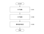
- the observation data collection engine 160 and the observation data pre-processing engine 130 may also be called a log collection unit and a log processing unit, respectively. An overview of the operation of the abnormality location estimation device 100 will be explained following the steps in the flow of FIG. 2.
- the observation data collection engine 160 collects observation data (logs generated by devices, etc.) from a communication network.
- the observation data preprocessing engine 130 determines the label y i to which the generated log belongs, and stores the log in the observation data DB 140 for each set of logs with the same label (z j described later). In other words, logs are stored in the observation data DB 140 for each log that has the same cause of occurrence.
- the observation data collection engine 160 determines the label, which will be described later, and the operator selects one of them in advance.
- two or three of the three methods may be selected, and the operator may check the labels assigned by each method and select the appropriate one.
- the causal model construction engine 110 constructs a causal model using existing methods (methods such as those in Non-Patent Documents 2, 3, and 4).
- the causal model inference engine 120 determines the value of the observation node based on the occurrence status of the logs stored in the observation data DB 140, estimates the abnormality location, and outputs the estimated abnormality location to the output interface 150.
- the output interface 150 displays to the user the location of an anomaly in the communication network and the maximum posterior probability at that time.
- the output interface 150 can add a node to the causal graph and also allow the user to correct any changes in causal relationships that result from this.
- the abnormality location estimation device 100 may be a single device (computer) or may consist of multiple devices.
- the functional unit that estimates the abnormality location using the log processed by the observation data preprocessing engine 130 may be called the "abnormality location estimation unit.”
- observation data DB 140 corresponds to the "anomaly location estimation unit.”
- the abnormality location estimation unit uses a functional unit based on a method (Non-Patent Document 3) that uses a causal model to estimate the abnormality location from observation data at the time of an abnormality, but the abnormality location estimation unit is not limited to using this method.
- observation data collection engine 160 and the observation data pre-processing engine 130 may be configured as a single device, which may be called a log processing device.
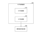
- FIG. 3 shows an example of the configuration of the log processing device 200.
- the log collection device 200 includes a log collection unit 210 and a log processing unit 220.
- FIG. 3 also shows an abnormality location estimation unit 300.
- the log collection unit 210 and the log processing unit 220 correspond to the observation data collection engine 160 and the observation data pre-processing engine 130, respectively.
- the abnormality location estimation unit 300 is located outside the log collection device 200, but the abnormality location estimation unit 300 may be located inside the log collection device 200.
- the log collection unit 210 collects logs from the communication network.
- the log processing unit 220 determines the cause of each log collected by the log collection unit 210, and inputs multiple logs with the same cause to the anomaly location estimation unit 300.
- Any of the devices described in this specification can be realized, for example, by causing a computer to execute a program.
- This computer may be a physical computer or a virtual machine on the cloud.
- the device can be realized by using hardware resources such as a CPU and memory built into a computer to execute a program corresponding to the processing performed by the device.
- the program can be recorded on a computer-readable recording medium (such as a portable memory) and then stored or distributed.
- the program can also be provided via a network such as the Internet or email.
- FIG. 4 is a diagram showing an example of the hardware configuration of the computer.
- the computer in FIG. 4 has a drive device 1000, an auxiliary storage device 1002, a memory device 1003, a CPU 1004, an interface device 1005, a display device 1006, an input device 1007, an output device 1008, etc., all of which are interconnected by a bus BS.
- the program that realizes the processing on the computer is provided by a recording medium 1001, such as a CD-ROM or a memory card.
- a recording medium 1001 storing the program is set in the drive device 1000, the program is installed from the recording medium 1001 via the drive device 1000 into the auxiliary storage device 1002.
- the program does not necessarily have to be installed from the recording medium 1001, but may be downloaded from another computer via a network.
- the auxiliary storage device 1002 stores the installed program as well as necessary files, data, etc.
- the memory device 1003 When an instruction to start a program is received, the memory device 1003 reads out and stores the program from the auxiliary storage device 1002.
- the CPU 1004 realizes the functions related to the device in accordance with the program stored in the memory device 1003.
- the interface device 1005 is used as an interface for connecting to a network.
- the display device 1006 displays a GUI (Graphical User Interface) based on a program.
- the input device 1007 is composed of a keyboard and mouse, buttons, a touch panel, or the like, and is used to input various operational instructions.
- the output device 1008 outputs the results of calculations.
- the operation of the anomaly location estimating device 100 will be described in more detail below. Note that, in this embodiment, it is assumed that a communication network configured with routers is the target, but this is only an example. The technology according to the present invention is applicable regardless of the type of nodes that configure the communication network.
- FIG. 5 shows an example of a communications network from which the observation data collection engine 160 collects observation data.
- this communications network is a network in which routers 1 to 6 are connected as shown.
- routers 1 and 2 are directly connected and are adjacent to each other.
- Routers 1 and 4 are not directly connected and are not adjacent to each other.
- the causal model construction engine 110 constructs the causal model shown in FIG. 6 for the communication network (physical layer network) shown in FIG. 5 based on the knowledge of an expert operator, etc.
- the causal model consists of device nodes that represent the state of each device (router) in the communication network, and observation nodes that represent whether a log (e.g., syslog related to link down) has been generated from the device. In other words, the observation nodes represent the observation results of each device.
- the causal model may also be called a Bayesian network.
- Router 1 which is an equipment node
- Routers 1 and 2 which are observation nodes. This indicates that if an abnormality occurs in Router 1, it may affect the observation data of Router 1 and the observation data of Router 2.
- router 2 which is an equipment node, is connected to routers 1, 2, 3, and 6, which are observation nodes. This indicates that if an abnormality occurs in router 2, it may affect the observation data of routers 1, 2, 3, and 6.
- observation data preprocessing engine 130 assigns a label indicating the cause of the log generation to each log collected by the observation data collection engine 160, and stores the labeled logs in the observation data DB 140.
- the causal model inference engine 120 performs anomaly location estimation for each log with the same assigned label value. The operation of the observation data preprocessing engine 130 will be described in more detail below.
- logs generated between time t and t+ ⁇ are denoted by x 1 , ..., x N.
- ⁇ is a time width for executing the anomaly location estimation process, which is determined in advance by any method. If it is desired to obtain an estimation result within one minute after the occurrence of a fault, ⁇ is set to 30 seconds, for example. N is the number of logs generated.
- x 1 , ..., x N are input to an abnormality part estimation unit to perform abnormality part processing.
- the estimation accuracy decreases due to the above-mentioned problem.
- the value of yi is a positive integer value from 1 to M, where M is an arbitrary value.
- the label yi represents the cause of the log occurrence, such as a failure occurring in the communication network, construction work, or user-caused events, and M is the total number of types of these causes.
- 1 represents a log caused by failure A
- 2 represents a log caused by failure B.
- the observation data pre-processing engine 130 analyzes these logs and finds that x1 , x2 , and x4 occurred due to failure A, and x3 and x5 occurred due to failure B, then y1 , y2 , and y4 are set to 1, and y3 and y5 are set to 2.
- the observation data preprocessing engine 130 inputs z j to the anomaly location estimation unit.
- logs with the same value of y i that is, logs with the same failure cause that generated the logs, are input to the anomaly location estimation unit.
- the observation data pre-processing engine 130 stores z j in the observation data DB 140. This means that the logs are stored in the observation data DB 140 for each log that has the same failure cause that caused the log.
- the label determination method is not limited to a specific method, but in this embodiment, the following three examples, determination method example 1 to 3, will be described. Note that any two of determination method example 1 to 3, or all of determination method example 1 to 3, may be combined to determine the log generation cause.
- Decision method example 1 In the determination method example 1, it is assumed that the events that cause the problems in a communication network and the patterns of log occurrences due to the problems are known. In this case, the observation data preprocessing engine 130 creates rules (e.g., cause 1 causes device A to generate log B, etc.) in sequence using the known problems and the patterns of log occurrences, and assigns each rule from 1 to M.
- rules e.g., cause 1 causes device A to generate log B, etc.
- the observation data preprocessing engine 130 When the observation data preprocessing engine 130 acquires an occurring log x i , it checks which rule the log applies to and determines the value of y i as a value representing the rule that applies. In this case, M may be set to the total number of rules.
- Determination method example 2 In the determination method example 2, the observation data preprocessing engine 130 heuristically determines the value of yi using external information that determines the cause of the log generation. Here, it is assumed that the observation data preprocessing engine 130 is capable of acquiring the external information necessary to determine the value of yi , for example, periodically or as needed.
- observation data pre-processing engine 130 determines that construction work was carried out in the communication network from time t to t+ ⁇ , it determines that the log x i generated during that time is likely to be caused by the construction work, and sets a value representing the construction work to y i . Also, if the observation data pre-processing engine 130 determines that logs due to a fault C are constantly generated, it sets the label y i for the generated log x i to a value representing the fault C.
- the observation data preprocessing engine 130 detects that a log x i has occurred in a device that the user can operate, it sets the value of the label y i to a value indicating the user's cause, and determines that the other logs are caused by a fault that occurred between time t and t+ ⁇ , and sets the value of the label y i to a value indicating that fault.
- the value of the label yi can be determined for each log xi .
- values starting from 1 are assigned to the causes of construction, failures, and user operations that occurred in the past, and the value of M is increased each time the number of causes increases.
- Determination method example 3 In example determination method 3, the observational data pre-processing engine 130 uses an algorithm to determine the label values from the data.
- the method (algorithm) for determining the label value from the data is not limited to a specific method, but for example, a known method disclosed in Reference 1 (WO2022/259307A1) can be used. This method is a method for clustering alarms by cause.
- the observation data preprocessing engine 130 clusters logs generated from time t to t+ ⁇ , obtains a cluster value indicating which cluster each log belongs to, and uses the obtained cluster value as the value of y i for the log belonging to that cluster. This makes it possible to assign a label to the log for each factor. In this case, the maximum value of the cluster value can be used as the value of M. Note that a method other than the method disclosed in Reference 1 may be used as a method for classifying the factors of the logs by clustering.
- the processes themselves performed by the causal model construction engine 110 and the causal model inference engine 120 are existing technologies.
- the method of constructing a causal model by the causal model construction engine 110 is as described with reference to Fig. 5 and Fig. 6, and for example, a causal model is constructed from the physical (or logical) connection relationships of devices.
- logs are stored in the observation data DB 140 for each log with the same failure cause.
- the causal model inference engine 120 uses a causal model to infer an anomaly location for each log with the same failure cause (log with the same value of yi ).
- the node values are defined as follows:
- an equipment node is denoted as a i
- an observation node is denoted as b i , i ⁇ (1, . . . N), where N is the number of equipment.
- Each ai takes a value of 0 (normal state) or 1 (abnormal state). It is possible for ai to take multiple values, not just 0 or 1, and in that case, the minimum value is the normal state, the maximum value is the abnormal state, and a value c between them is defined as a value that indicates abnormality at the rate of "c/(maximum value-minimum value)".
- Each b i takes a value of 0 or 1, where 1 indicates that a log occurred at the i-th router. Note that instead of the binary values of 0 and 1, it is also possible for it to take multiple values of 3 or more, in which case the value is defined as the number of logs that occurred at the i-th router.
- the input values to the above causal model can be determined (calculated) by the causal model inference engine 120 from the logs read from the observation data DB 140.
- the inference itself using the causal model is the same as the method in Non-Patent Document 3, and inference is performed by defining the prior probability P(a i ) and the conditional probability P(b j
- the observation data pre-processing engine 130 assigns a label to each log indicating the cause of the log's occurrence, and the anomaly point estimation unit estimates the anomaly point for each log that has the same assigned label value. This makes it possible to improve the accuracy of estimating anomalies in a communication network.
- Additional Notes Memory, at least one processor coupled to the memory; Including, The processor, Collect logs from communication networks, The log processing device determines the cause of each collected log, and inputs multiple logs having the same cause to an anomaly location estimation unit.
- the log processing device assigns a label indicating a cause of occurrence to each collected log, and inputs a plurality of logs having the same assigned label value to the abnormality portion estimation unit.
- Additional Note 3 3.
- a log processing method executed by a log processing device comprising: A log collection step of collecting logs from a communication network; a log processing step of determining a cause of occurrence of each log collected in the log collecting step, and inputting a plurality of logs having the same cause of occurrence to an abnormality part estimating unit.
- a non-transitory storage medium storing a program for causing a computer to function as a log collection unit and a log processing unit in the log processing device according to any one of claims 1 to 5.
- Anomaly location estimation device 110 Causal model construction engine 120 Causal model inference engine 130 Observation data pre-processing engine 140 Observation data DB 150 Output interface 160 Observation data collection engine 200 Log collection device 210 Log collection unit 220 Log processing unit 300 Anomaly location estimation unit 1000 Drive device 1001 Recording medium 1002 Auxiliary storage device 1003 Memory device 1004 CPU 1005 Interface device 1006 Display device 1007 Input device 1008 Output device
Landscapes
- Engineering & Computer Science (AREA)
- Computer Networks & Wireless Communication (AREA)
- Signal Processing (AREA)
- Debugging And Monitoring (AREA)
Abstract
ログ処理装置において、通信ネットワークからログを収集するログ収集部と、前記ログ収集部により収集された各ログの発生要因を判定し、発生要因が同じ複数のログを異常箇所推定部に入力するログ処理部とを備える。
Description
本発明は、通信ネットワークから収集したログに基づいて、通信ネットワークの異常箇所を推定する技術に関連するものである。
通信事業者にとって、通信ネットワーク内に発生する異常に対して、異常の状態の把握や迅速な対応は重要である。こうした中で、通信ネットワーク内の異常を早期に検知するための研究や、異常箇所の推定を行う研究が行われている(非特許文献1、2)。
異常箇所を推定する手法として、ベイジアンネットワークを用いて、異常箇所とそれによって引き起こされる通信ネットワーク内のデータ(観測データと呼ぶ)の変化の関係性をモデル化(因果モデルと呼ぶ)し、異常時の観測データから異常箇所を推定する手法が提案されている(非特許文献3)。
非特許文献3では、ネットワークのリンクのup/downのデータを用いてルータの正常・異常を判定する。エキスパートの知識から、ルータの正常・異常は隣接しているリンクの観測データのみに影響があるという仮定のもと、ネットワークのトポロジーの隣接関係を用いて因果モデルを構築する。
また、非特許文献4では、通信ネットワーク内の様々な異常に対して、異常箇所推定を行えるように、物理的な対向装置のリンクダウン以外にも様々なログを用いている。例えば、ルータなどの機器からは、CPUやメモリ、インタフェースモジュールなどの機器の状態(機器レイヤと呼ぶ)を表すログ、物理的に接続している対向装置とのインタフェースの接続などの状態(物理レイヤと呼ぶ)を表すログ、及び、論理的に接続している機器の状態(論理レイヤと呼ぶ)を表すログなど、異常になったレイヤごとに異なったログが出力される。これらを用いて、異常パターン、あるいは生成されるログの原因となりえる事象ごとにオペレータの知識を用いて因果モデルを作成し、異常箇所の推定を行う。
K. Tajiri, T. Iwata, Y. Matsuo and K. Watanabe, "Fault Detection of ICT systems with Deep Learning Model for Missing Data," 2021 IFIP/IEEE International Symposium on Integrated Network Management (IM), 2021, pp. 445-451.
Y. Matsuo, Y. Nakano, A. Watanabe, K. Watanabe, K. Ishibashi, and K. Kawahara, "Root-cause diagnosis for rare failures using Bayesian network with dynamic modification," Proc. IEEE, ICC, 2018.
Srikanth Kandula, Dina Katabi, and Jean-philippe Vasseur. Shrink: A tool for failure diagnosis in IP networks. Proceedings of the 2005 ACM SIGCOMM workshop on Mining network data, pages 173-178, 2005.
He Yan, Lee Breslau, Zihui Ge, Dan Massey, Dan Pei, and Jennifer Yates. G-RCA: A Generic Root Cause Analysis Platform for Service Quality Management in Large IP Networks. IEEE/ACM Transactions on Networking, 20(6):1734-1747, 2012.
非特許文献3、4ともに障害発生時のログを用いて異常箇所の推定を行う。しかし、同時に複数の障害が発生することは想定しておらず、障害発生時にはその一つの障害に関するログしか発生しないという前提がある。
しかし、実際の通信ネットワークにおいては同時に複数の障害が発生することもある。また、過去に発生した障害に関連して定期的にログが出現する、通信サービスを提供している顧客の操作によりログが発生する、同時間帯に工事を実施していた工事によりログが発生する、など、発生した障害と関わりがないログも出現している。
その結果、異常箇所推定手法の仮定が成り立たないため、同時発生した異常箇所を推定できない、過去に発生した障害のログが影響して推定箇所が間違ってしまう、など、推定精度が低下するという課題がある。
本発明は上記の点に鑑みてなされたものであり、通信ネットワーク内の異常箇所の推定精度を向上させるための技術を提供することを目的とする。
開示の技術によれば、通信ネットワークからログを収集するログ収集部と、
前記ログ収集部により収集された各ログの発生要因を判定し、発生要因が同じ複数のログを異常箇所推定部に入力するログ処理部と
を備えるログ処理装置が提供される。
前記ログ収集部により収集された各ログの発生要因を判定し、発生要因が同じ複数のログを異常箇所推定部に入力するログ処理部と
を備えるログ処理装置が提供される。
開示の技術によれば、通信ネットワーク内の異常箇所の推定精度を向上させるための技術が提供される。
以下、図面を参照して本発明の実施の形態(本実施の形態)を説明する。以下で説明する実施の形態は一例に過ぎず、本発明が適用される実施の形態は、以下の実施の形態に限られるわけではない。
(実施の形態の概要)
本実施の形態では、通信ネットワークにおいて、障害が発生する場合に、発生した障害と関係がないログも出現する状況を想定する。このような状況において、後述する異常箇所推定装置100が、発生した各ログに対して、どの障害に関連するログか、を示すラベリングを行うことで、異常箇所の推定精度を向上させることとしている。なお、「異常箇所」を「障害箇所」、「故障個所」などと呼んでもよい。
本実施の形態では、通信ネットワークにおいて、障害が発生する場合に、発生した障害と関係がないログも出現する状況を想定する。このような状況において、後述する異常箇所推定装置100が、発生した各ログに対して、どの障害に関連するログか、を示すラベリングを行うことで、異常箇所の推定精度を向上させることとしている。なお、「異常箇所」を「障害箇所」、「故障個所」などと呼んでもよい。
すなわち、本実施の形態では、通信ネットワークにおいて、各障害、工事、ユーザによる操作などの何らかの要因によってログが発生するという自然法則に着目し、異常箇所推定装置100が、各ログに対してログが発生した要因を表すラベルを付与し、付与したラベルの値が同じログごとに、異常箇所推定手法を用いて異常箇所を推定することとしている。以下、本実施の形態における装置構成、及び装置動作を詳細に説明する。
(装置構成例)
図1に、本実施の形態における異常箇所推定装置100の構成例を示す。図1に示すように、異常箇所推定装置100は、観測データ収集エンジン160、観測データDB140、観測データ前処理エンジン130、因果モデル構築エンジン110、因果モデル推論エンジン120、利用者への出力インタフェース150を有する。
図1に、本実施の形態における異常箇所推定装置100の構成例を示す。図1に示すように、異常箇所推定装置100は、観測データ収集エンジン160、観測データDB140、観測データ前処理エンジン130、因果モデル構築エンジン110、因果モデル推論エンジン120、利用者への出力インタフェース150を有する。
なお、観測データ収集エンジン160、観測データ前処理エンジン130、因果モデル構築エンジン110、因果モデル推論エンジン120をそれぞれ、観測データ収集部160、観測データ前処理部130、因果モデル構築部110、因果モデル推論部120と呼んでもよい。また、観測データ収集エンジン160、観測データ前処理エンジン130、因果モデル構築エンジン110、因果モデル推論エンジン120をそれぞれ、観測データ収集回路160、観測データ前処理回路130、因果モデル構築回路110、因果モデル推論回路120と呼んでもよい。
また、異常箇所推定装置100をログ処理装置と呼んでもよい。また、観測データ収集エンジン160、観測データ前処理エンジン130をそれぞれ、ログ収集部、ログ処理部と呼んでもよい。異常箇所推定装置100の動作概要を図2のフローの手順に沿って説明する。
S101において、観測データ収集エンジン160は、通信ネットワークから観測データ(機器から発生するログ等)を収集する。S102において、観測データ前処理エンジン130は、発生したログが属するラベルyiを判定し、ラベルが同じログの集合(後述するzj)ごとに、ログを観測データDB140に格納する。つまり、発生した要因が同じログごとに、ログを観測データDB140に格納する。
本実施の形態では、観測データ収集エンジン160がラベルを判定する方法として、後述する3通りの方法があるが、そのうち1つを事前にオペレータが選択しておく。あるいは、3通りのうち、2つ、あるいは3つを選択し、それぞれの方法で付与されたラベルをオペレータが確認し、適切なものを選択する方法を用いてもよい。
因果モデル構築エンジン110は、既存手法(非特許文献2、3、4などの手法)により、因果モデルを構築する。S103において、因果モデル推論エンジン120は観測データDB140へ格納されたログの発生状況をもとに、観測ノードの値を決定し、異常箇所の推定を実施し、出力インタフェース150に推定結果である異常箇所を出力する。
出力インタフェース150は、利用者に対して通信ネットワークの中の異常発生箇所とその際の最大事後確率等を表示する。また、出力インタフェース150は、運用システムに新たにマシンが追加された際などは、因果グラフへのノードの追加を行い、また、それに伴う因果関係の変化を利用者に修正させることもできる。
異常箇所推定装置100は、1つの装置(コンピュータ)であってもよいし、複数の装置からなるものであってもよい。
また、観測データ前処理エンジン130で処理されたログを用いて異常箇所を推定する機能部を「異常箇所推定部」と呼んでもよい。
図1の構成においては、「観測データDB140、観測データ前処理エンジン130、因果モデル構築エンジン110、因果モデル推論エンジン120、利用者への出力インタフェース150」の部分が「異常箇所推定部」に相当する。
なお、本実施の形態では、異常箇所推定部として、因果モデルを用いて異常時の観測データから異常箇所を推定する手法(非特許文献3)に基づく機能部を用いているが、異常箇所推定部は、この手法を用いるものに限定されない。
また、観測データ収集エンジン160と観測データ前処理エンジン130により1つの装置を構成し、それをログ処理装置と呼んでもよい。
図3にログ処理装置200の構成例を示す。図3に示すように、ログ収集装置200は、ログ収集部210、及びログ処理部220を含む。図3には、異常箇所推定部300も示されている。
ログ収集部210とログ処理部220はそれぞれ観測データ収集エンジン160と観測データ前処理エンジン130に対応する。図3では、ログ収集装置200の外部に異常箇所推定部300があるが、異常箇所推定部300が、ログ収集装置200の内部にあってもよい。
ログ収集部210は、通信ネットワークからログを収集する。ログ処理部220は、前記ログ収集部210により収集された各ログの発生要因を判定し、発生要因が同じ複数のログを異常箇所推定部300に入力する。
(ハードウェア構成例)
本明細書に記載したいずれの装置(異常箇所推定装置100、ログ処理装置200)も、例えば、コンピュータにプログラムを実行させることにより実現できる。このコンピュータは、物理的なコンピュータであってもよいし、クラウド上の仮想マシンであってもよい。
本明細書に記載したいずれの装置(異常箇所推定装置100、ログ処理装置200)も、例えば、コンピュータにプログラムを実行させることにより実現できる。このコンピュータは、物理的なコンピュータであってもよいし、クラウド上の仮想マシンであってもよい。
すなわち、当該装置は、コンピュータに内蔵されるCPUやメモリ等のハードウェア資源を用いて、当該装置で実施される処理に対応するプログラムを実行することによって実現することが可能である。上記プログラムは、コンピュータが読み取り可能な記録媒体(可搬メモリ等)に記録して、保存したり、配布したりすることが可能である。また、上記プログラムをインターネットや電子メール等、ネットワークを通して提供することも可能である。
図4は、上記コンピュータのハードウェア構成例を示す図である。図4のコンピュータは、それぞれバスBSで相互に接続されているドライブ装置1000、補助記憶装置1002、メモリ装置1003、CPU1004、インタフェース装置1005、表示装置1006、入力装置1007、出力装置1008等を有する。
当該コンピュータでの処理を実現するプログラムは、例えば、CD-ROM又はメモリカード等の記録媒体1001によって提供される。プログラムを記憶した記録媒体1001がドライブ装置1000にセットされると、プログラムが記録媒体1001からドライブ装置1000を介して補助記憶装置1002にインストールされる。但し、プログラムのインストールは必ずしも記録媒体1001より行う必要はなく、ネットワークを介して他のコンピュータよりダウンロードするようにしてもよい。補助記憶装置1002は、インストールされたプログラムを格納すると共に、必要なファイルやデータ等を格納する。
メモリ装置1003は、プログラムの起動指示があった場合に、補助記憶装置1002からプログラムを読み出して格納する。CPU1004は、メモリ装置1003に格納されたプログラムに従って、当該装置に係る機能を実現する。インタフェース装置1005は、ネットワークに接続するためのインタフェースとして用いられる。表示装置1006はプログラムによるGUI(Graphical User Interface)等を表示する。入力装置1007はキーボード及びマウス、ボタン、又はタッチパネル等で構成され、様々な操作指示を入力させるために用いられる。出力装置1008は演算結果を出力する。
(動作例)
以下では、異常箇所推定装置100の動作を、より詳細に説明する。なお、本実施の形態では、ルータにより構成される通信ネットワークを対象とすることを想定しているが、これは一例である。本発明に係る技術は、通信ネットワークを構成するノードの種類に依らずに適用可能である。
以下では、異常箇所推定装置100の動作を、より詳細に説明する。なお、本実施の形態では、ルータにより構成される通信ネットワークを対象とすることを想定しているが、これは一例である。本発明に係る技術は、通信ネットワークを構成するノードの種類に依らずに適用可能である。
<因果モデルについて>
本発明に係る技術に係る前処理について説明する前に、まず、非特許文献3に基づく、因果モデルの構築について説明する。
本発明に係る技術に係る前処理について説明する前に、まず、非特許文献3に基づく、因果モデルの構築について説明する。
図5に、観測データ収集エンジン160が観測データを収集する対象となる通信ネットワークの例を示す。図5に示すように、この通信ネットワークは、ルータ1~6が図示するとおりに接続されたネットワークである。例えば、ルータ1とルータ2は直接に接続されており、これらは互いに隣接関係にある。ルータ1とルータ4は直接には接続されておらず、これらは隣接関係にない。
因果モデル構築エンジン110は、エキスパートオペレーターの知識等に基づいて、図5に示す通信ネットワーク(物理レイヤのネットワーク)に対して、図6に示す因果モデルを構築する。因果モデルは、通信ネットワーク内の機器(ルータ)に対して、各機器の状態を表す機器ノードと、その機器からログ(例:リンクダウンに関するsyslog)が発生したかどうかを表す観測ノードからなる。つまり、観測ノードは、各機器の観測結果を表す。なお、因果モデルをベイジアンネットワークと呼んでもよい。
例えば、図6の因果モデルにおいて、機器ノードのルータ1は、観測ノードのルータ1、2と接続されている。これは、ルータ1に異常が発生した場合に、ルータ1の観測データとルータ2の観測データに影響する可能性があるということを示している。
また、例えば、図6の因果モデルにおいて、機器ノードのルータ2は、観測ノードのルータ1、2、3、6と接続されている。これは、ルータ2に異常が発生した場合に、ルータ1、2、3、6のそれぞれの観測データに影響する可能性があるということを示している。
<観測データ前処理エンジン130についての詳細説明>
前述したとおり、本実施の形態では、通信ネットワークにおいて、各障害、工事、ユーザによる操作など何らかの要因によってログが発生するという自然法則に着目している。そのため、観測データ前処理エンジン130は、観測データ収集エンジン160により収集された各ログに対して、ログが発生した要因を表すラベルを付与し、ラベルを付与したログを観測データDB140に格納する。因果モデル推論エンジン120は、付与したラベルの値が同じログごとに異常箇所推定を行う。以下、観測データ前処理エンジン130の動作をより詳細に説明する。
前述したとおり、本実施の形態では、通信ネットワークにおいて、各障害、工事、ユーザによる操作など何らかの要因によってログが発生するという自然法則に着目している。そのため、観測データ前処理エンジン130は、観測データ収集エンジン160により収集された各ログに対して、ログが発生した要因を表すラベルを付与し、ラベルを付与したログを観測データDB140に格納する。因果モデル推論エンジン120は、付与したラベルの値が同じログごとに異常箇所推定を行う。以下、観測データ前処理エンジン130の動作をより詳細に説明する。
まず、時刻tからt+τまでの間に発生したログをx1,…,xNとする。ここで、τは任意の方法で事前に決定する、異常箇所推定処理を実行する時間幅である。障害発生から1分以内に推定結果を得たい場合は、例えばτを30秒とする。Nは発生したログ数である。
従来技術では、x1,…,xNを異常箇所推定部に入力して、異常箇所処理を行っていた。しかし、x1,…,xNをそのまま用いる場合、前述した問題があるため、推定精度が低下する。
そこで、観測データ前処理エンジン130は、各xi(i∈{1,…,N})に対して、各ログが発生した要因を表すラベルyi(i∈{1,…N})を求め、{xi,yi}N
i=1を作成する。ここで、yiの値は1からMの正の整数値とし、Mは任意に与えるものとする。ラベルyiは通信ネットワーク内で発生する障害、工事、ユーザ起因など、ログが発生した要因を表し、Mはそれら要因の種類の総数である。
以下では、ラベルyiの値が計算できた場合にどのように課題を解決するかを説明し、その後、xiに対するyiの値の計算方法とMの与え方について説明する。
例えば、yiの値において、1は障害Aが要因で発生したログを表し、2は障害Bが要因で発生したログを表すとする。この時、ある時刻tからt+τで発生したログx1,…,x5に対して、観測データ前処理エンジン130が、これらのログを分析した結果、障害Aによりx1,x2,x4が発生し、障害Bによりx3,x5が発生したと判明した場合、y1,y2,y4をそれぞれ1とし、y3,y5をそれぞれ2とする。
次に、観測データ前処理エンジン130は、あるj∈1,…,Mに対してzj={xi|yi=j,i∈1,…,N}を計算する。つまり、yi=jであるログの集合zjを求める。
観測データ前処理エンジン130は、zjが空集合でなければ、zjを異常箇所推定部に入力する。これはyiの値が同じ、つまりログが発生した障害要因が同じログを異常箇所推定部に入力することである。これにより、異常箇所推定部が前提としていた「ある障害に関するログだけが発生しており、そのログを入力として障害箇所を推定する」という仮定を満たすことができるようになるため、異常箇所の推定精度が向上する。
より具体的には、観測データ前処理エンジン130は、zjが空集合でなければ、zjを観測データDB140に格納する。これは、ログが発生した障害要因が同じログごとに、ログを観測データDB140に格納することである。
観測データ前処理エンジン130は、上記の処理をj=1からj=Mまで、jを1ずつ増加させながら繰り返し行う。例えば、空集合でないzjが得られるjの個数がkであるとした場合、ログxi(i∈1,…,N)の集合に対して、ログを要因ごとにk個に分割し、kのそれぞれについて異常箇所推定手法を実施することとなる。
次に、観測データ前処理エンジン130によるラベルyiの決定方法について説明する。ラベルの決定方法は特定の方法に限定されないが、本実施の形態では、下記の決定方法例1~3の3つの例について説明する。なお、決定方法例1~3のうちのいずれか2つ、又は、決定方法例1~3全部を組み合わせて、ログ発生要因を判定してもよい。
決定方法例1:
決定方法例1では、通信ネットワークにおいて要因となる事象とそれによるログの発生パターンが既知であるとする。この場合、観測データ前処理エンジン130が、既知である要因とそのログの発生パターンを用いてルール(例:要因1は機器AでログBが発生する、など)を順々に作成し、各ルールを1からMに割り当てる。
決定方法例1では、通信ネットワークにおいて要因となる事象とそれによるログの発生パターンが既知であるとする。この場合、観測データ前処理エンジン130が、既知である要因とそのログの発生パターンを用いてルール(例:要因1は機器AでログBが発生する、など)を順々に作成し、各ルールを1からMに割り当てる。
そして、観測データ前処理エンジン130は、発生したログxiを取得した際には、そのログがどのルールに当てはまるか確認し、yiの値を当てはまるルールを表す値に決定する。また、この場合、Mはルールの総数とすれば良い。
決定方法例2:
決定方法例2では、観測データ前処理エンジン130は、ログの発生要因を決定づける外部情報を用いて、ヒューリスティックにyiの値を決定する。ここでは、観測データ前処理エンジン130は、yiの値を決定するために必要な外部情報を、例えば定期的に、あるいは必要に応じて取得可能であるものとする。
決定方法例2では、観測データ前処理エンジン130は、ログの発生要因を決定づける外部情報を用いて、ヒューリスティックにyiの値を決定する。ここでは、観測データ前処理エンジン130は、yiの値を決定するために必要な外部情報を、例えば定期的に、あるいは必要に応じて取得可能であるものとする。
例えば、観測データ前処理エンジン130が、ある時刻tからt+τにおいて、通信ネットワーク内で工事が実施されていたことを把握すると、当該時間に発生したログxiは工事が要因となっている可能性が高いと判断し、yiに当該工事を表す値を設定する。また、観測データ前処理エンジン130は、障害Cによるログが定常的に発生していることを把握した場合、発生しているログxiに対するラベルyiを、障害Cを表す値にする。
また、観測データ前処理エンジン130は、ユーザが操作できる機器においてログxiが発生したことを検知した場合、ラベルyiの値を、ユーザ起因を表す値にする。そして、それ以外のログは時刻tからt+τに発生した障害が要因となっているログであると判断し、ラベルyiの値を、その障害を表す値とする。
上記のようにして、各ログxiに対して、ラベルyiの値を決定することができる。この場合、過去に発生した工事、障害、ユーザ操作の要因に対して順に1から値を割り当ていき、要因数が増えるごとにMの値を増やしていけば良い。
決定方法例3:
決定方法例3では、観測データ前処理エンジン130は、データからラベルの値を決定するアルゴリズムを使用する。
決定方法例3では、観測データ前処理エンジン130は、データからラベルの値を決定するアルゴリズムを使用する。
データからラベルの値を決定する手法(アルゴリズム)は、特定の手法に限定されないが、例えば、参考文献1(WO2022/259307A1)に開示された既知の手法を用いることができる。この手法は、要因ごとにアラームをクラスタリングする手法である。
この手法に基づき、観測データ前処理エンジン130は、時刻tからt+τに発生したログをクラスタリングし、各ログがどのクラスタに属するかを示すクラスタ値を求め、求めたクラスタ値を、そのクラスタに属するログのyiの値として用いる。これにより、要因ごとに、ログにラベルを付与することができる。この場合、Mの値として、クラスタ値の最大値を用いればよい。なお、クラスタリングをしてログの要因を分類する手法として、参考文献1に開示された手法以外の手法を用いることとしてもよい。
<因果モデル構築エンジン110及び因果モデル推論エンジン120についての詳細説明>
本実施の形態において、因果モデル構築エンジン110及び因果モデル推論エンジン120による処理自体は既存技術である。因果モデル構築エンジン110による因果モデル構築の方法は、図5、図6を参照して説明したとおりであり、例えば、機器の物理的(あるいは論理的)な接続関係から因果モデルを構築する。
本実施の形態において、因果モデル構築エンジン110及び因果モデル推論エンジン120による処理自体は既存技術である。因果モデル構築エンジン110による因果モデル構築の方法は、図5、図6を参照して説明したとおりであり、例えば、機器の物理的(あるいは論理的)な接続関係から因果モデルを構築する。
上述した処理により、観測データDB140には、発生した障害要因が同じログごとに、ログが格納されている。因果モデル推論エンジン120は、発生した障害要因が同じログ(yiの値が同じログ)ごとに、因果モデルを用いて異常箇所推定を行う。具体的には、以下のようにノードの値を定義する。
異常箇所推定の対象となるシステム(通信ネットワーク)の因果モデルにおける機器ノードをai、観測ノードをbi,i∈(1,…N)とする。ここでのNは機器数である。
各aiは0(正常状態)か1(異常状態)の値を取るとする。なお、0か1の2値ではなく、3値以上の多値を取ることも可能であり、その場合は最小値が正常状態、最大値が異常状態、その間の値cは、「c/(最大値-最小値)」の割合で異常となっていることを意味する値、などのように定義する。
各biは0か1の値を取るとし、1はi番目のルータでログが発生したことを表す。なお、0か1の2値ではなく、3値以上の多値を取ることも可能であり、その場合はi番目のルータで発生したログの発生件数を値とするなどのように定義する。
上記の因果モデルへの入力値については、因果モデル推論エンジン120が、観測データDB140から読み出したログから決定(計算)することができる。
因果モデルを用いた推論自体は非特許文献3での手法と同じであり、事前確率P(ai)と条件付き確率P(bj|ai)を規定し、推論を行う。
(実施の形態に係る技術の効果について)
上述したとおり、観測データ前処理エンジン130が、各ログに対してログが発生した要因を表すラベルを付与し、異常箇所推定部が、付与したラベルの値が同じログごとに異常箇所推定を行うこととしたので、通信ネットワーク内の異常箇所の推定精度を向上させことができる。
上述したとおり、観測データ前処理エンジン130が、各ログに対してログが発生した要因を表すラベルを付与し、異常箇所推定部が、付与したラベルの値が同じログごとに異常箇所推定を行うこととしたので、通信ネットワーク内の異常箇所の推定精度を向上させことができる。
以上の実施形態に関し、更に以下の付記を開示する。
<付記>
(付記項1)
メモリと、
前記メモリに接続された少なくとも1つのプロセッサと、
を含み、
前記プロセッサは、
通信ネットワークからログを収集し、
収集された各ログの発生要因を判定し、発生要因が同じ複数のログを異常箇所推定部に入力する
ログ処理装置。
(付記項2)
前記プロセッサは、収集された各ログに発生要因を表すラベルを付与し、付与したラベルの値が同じ複数のログを前記異常箇所推定部に入力する
付記項1に記載のログ処理装置。
(付記項3)
前記プロセッサは、ログの発生要因となる事象と当該事象によるログ発生のパターンに基づくルールを用いて、各ログの発生要因を判定する
付記項1又は2に記載のログ処理装置。
(付記項4)
前記プロセッサは、ログの発生要因に関連する外部情報を用いて、各ログの発生要因を判定する
付記項1又は2に記載のログ処理装置。
(付記項5)
前記プロセッサは、ログをクラスタリングし、各ログがどのクラスタに属するかを示すクラスタ値を求め、求めたクラスタ値に基づいて、各ログの発生要因を判定する
付記項1又は2に記載のログ処理装置。
(付記項6)
ログ処理装置が実行するログ処理方法であって、
通信ネットワークからログを収集するログ収集ステップと、
前記ログ収集ステップにより収集された各ログの発生要因を判定し、発生要因が同じ複数のログを異常箇所推定部に入力するログ処理ステップと
を備えるログ処理方法。
(付記項7)
コンピュータを、付記項1ないし5のうちいずれか1項に記載のログ処理装置におけるログ収集部及びログ処理部として機能させるためのプログラムを記憶した非一時的記憶媒体。
以上、本実施の形態について説明したが、本発明はかかる特定の実施形態に限定されるものではなく、特許請求の範囲に記載された本発明の要旨の範囲内において、種々の変形・変更が可能である。
100 異常箇所推定装置
110 因果モデル構築エンジン
120 因果モデル推論エンジン
130 観測データ前処理エンジン
140 観測データDB
150 出力インタフェース
160 観測データ収集エンジン
200 ログ収集装置
210 ログ収集部
220 ログ処理部
300 異常箇所推定部
1000 ドライブ装置
1001 記録媒体
1002 補助記憶装置
1003 メモリ装置
1004 CPU
1005 インタフェース装置
1006 表示装置
1007 入力装置
1008 出力装置
110 因果モデル構築エンジン
120 因果モデル推論エンジン
130 観測データ前処理エンジン
140 観測データDB
150 出力インタフェース
160 観測データ収集エンジン
200 ログ収集装置
210 ログ収集部
220 ログ処理部
300 異常箇所推定部
1000 ドライブ装置
1001 記録媒体
1002 補助記憶装置
1003 メモリ装置
1004 CPU
1005 インタフェース装置
1006 表示装置
1007 入力装置
1008 出力装置
Claims (7)
- 通信ネットワークからログを収集するログ収集部と、
前記ログ収集部により収集された各ログの発生要因を判定し、発生要因が同じ複数のログを異常箇所推定部に入力するログ処理部と
を備えるログ処理装置。 - 前記ログ処理部は、前記ログ収集部により収集された各ログに発生要因を表すラベルを付与し、付与したラベルの値が同じ複数のログを前記異常箇所推定部に入力する
請求項1に記載のログ処理装置。 - 前記ログ処理部は、ログの発生要因となる事象と当該事象によるログ発生のパターンに基づくルールを用いて、各ログの発生要因を判定する
請求項1に記載のログ処理装置。 - 前記ログ処理部は、ログの発生要因に関連する外部情報を用いて、各ログの発生要因を判定する
請求項1に記載のログ処理装置。 - 前記ログ処理部は、ログをクラスタリングし、各ログがどのクラスタに属するかを示すクラスタ値を求め、求めたクラスタ値に基づいて、各ログの発生要因を判定する
請求項1に記載のログ処理装置。 - ログ処理装置が実行するログ処理方法であって、
通信ネットワークからログを収集するログ収集ステップと、
前記ログ収集ステップにより収集された各ログの発生要因を判定し、発生要因が同じ複数のログを異常箇所推定部に入力するログ処理ステップと
を備えるログ処理方法。 - コンピュータを、請求項1ないし5のうちいずれか1項に記載のログ処理装置におけるログ収集部及びログ処理部として機能させるためのプログラム。
Priority Applications (1)
| Application Number | Priority Date | Filing Date | Title |
|---|---|---|---|
| PCT/JP2023/030049 WO2025041236A1 (ja) | 2023-08-21 | 2023-08-21 | ログ処理装置、ログ処理方法、及びプログラム |
Applications Claiming Priority (1)
| Application Number | Priority Date | Filing Date | Title |
|---|---|---|---|
| PCT/JP2023/030049 WO2025041236A1 (ja) | 2023-08-21 | 2023-08-21 | ログ処理装置、ログ処理方法、及びプログラム |
Publications (1)
| Publication Number | Publication Date |
|---|---|
| WO2025041236A1 true WO2025041236A1 (ja) | 2025-02-27 |
Family
ID=94731846
Family Applications (1)
| Application Number | Title | Priority Date | Filing Date |
|---|---|---|---|
| PCT/JP2023/030049 Pending WO2025041236A1 (ja) | 2023-08-21 | 2023-08-21 | ログ処理装置、ログ処理方法、及びプログラム |
Country Status (1)
| Country | Link |
|---|---|
| WO (1) | WO2025041236A1 (ja) |
Citations (7)
| Publication number | Priority date | Publication date | Assignee | Title |
|---|---|---|---|---|
| WO2017154844A1 (ja) * | 2016-03-07 | 2017-09-14 | 日本電信電話株式会社 | 分析装置、分析方法および分析プログラム |
| JP2018124697A (ja) * | 2017-01-31 | 2018-08-09 | オムロン株式会社 | 情報処理装置、情報処理プログラムおよび情報処理方法 |
| US10992557B1 (en) * | 2018-11-09 | 2021-04-27 | Innovium, Inc. | Traffic analyzer for network device |
| JP2022061676A (ja) * | 2020-10-07 | 2022-04-19 | エヌ・ティ・ティ・コムウェア株式会社 | 学習装置、推定装置、シーケンス推定システムおよび方法、プログラム |
| JP2022130491A (ja) * | 2019-10-31 | 2022-09-06 | アシュラント,インコーポレーテッド | 独立したコンピューティングリソースを管理し、および同期させるためのシステム、方法、装置、およびコンピュータプログラム製品 |
| JP2022161102A (ja) * | 2021-04-08 | 2022-10-21 | 株式会社日立製作所 | 分散システム、及びデータ転送方法 |
| JP2023004324A (ja) * | 2021-06-25 | 2023-01-17 | キヤノン株式会社 | 画像形成装置、画像形成装置の制御方法、及びプログラム |
-
2023
- 2023-08-21 WO PCT/JP2023/030049 patent/WO2025041236A1/ja active Pending
Patent Citations (7)
| Publication number | Priority date | Publication date | Assignee | Title |
|---|---|---|---|---|
| WO2017154844A1 (ja) * | 2016-03-07 | 2017-09-14 | 日本電信電話株式会社 | 分析装置、分析方法および分析プログラム |
| JP2018124697A (ja) * | 2017-01-31 | 2018-08-09 | オムロン株式会社 | 情報処理装置、情報処理プログラムおよび情報処理方法 |
| US10992557B1 (en) * | 2018-11-09 | 2021-04-27 | Innovium, Inc. | Traffic analyzer for network device |
| JP2022130491A (ja) * | 2019-10-31 | 2022-09-06 | アシュラント,インコーポレーテッド | 独立したコンピューティングリソースを管理し、および同期させるためのシステム、方法、装置、およびコンピュータプログラム製品 |
| JP2022061676A (ja) * | 2020-10-07 | 2022-04-19 | エヌ・ティ・ティ・コムウェア株式会社 | 学習装置、推定装置、シーケンス推定システムおよび方法、プログラム |
| JP2022161102A (ja) * | 2021-04-08 | 2022-10-21 | 株式会社日立製作所 | 分散システム、及びデータ転送方法 |
| JP2023004324A (ja) * | 2021-06-25 | 2023-01-17 | キヤノン株式会社 | 画像形成装置、画像形成装置の制御方法、及びプログラム |
Similar Documents
| Publication | Publication Date | Title |
|---|---|---|
| US7113988B2 (en) | Proactive on-line diagnostics in a manageable network | |
| CN104796273B (zh) | 一种网络故障根源诊断的方法和装置 | |
| KR100714157B1 (ko) | 컴퓨터 기반 방법, 컴퓨터 판독 가능 기록 매체 및 데이터 처리 시스템 | |
| US8583779B2 (en) | Root cause analysis approach with candidate elimination using network virtualization | |
| US8656219B2 (en) | System and method for determination of the root cause of an overall failure of a business application service | |
| US7725774B2 (en) | Methods, systems, and media to correlate errors associated with a cluster | |
| CN113328872A (zh) | 故障修复方法、装置和存储介质 | |
| US20090063902A1 (en) | Preliminary Classification of Events to Facilitate Cause-Based Analysis | |
| US10728085B1 (en) | Model-based network management | |
| CN118520405B (zh) | 基于人工智能的云数据平台综合服务管理系统及方法 | |
| US8156319B2 (en) | Self-restarting network devices | |
| CN101507185A (zh) | 使用贝叶斯网络的电信网络中的故障定位 | |
| CN113973042A (zh) | 用于网络问题的根本原因分析的方法和系统 | |
| CN107210927A (zh) | 协议处理中的异常检测 | |
| JP3579834B2 (ja) | 管理可能なネットワークにおける事前対策オンライン診断 | |
| WO2025124097A1 (zh) | 一种问题定界的方法及装置 | |
| JP6954379B2 (ja) | 異常箇所特定装置、異常箇所特定方法及びプログラム | |
| CN118780665A (zh) | 设备运维质量分析方法、装置、电子设备及存储介质 | |
| JP7414135B2 (ja) | モデル構築装置、推定装置、モデル構築方法、推定方法及びプログラム | |
| JP2018124829A (ja) | 状態判定装置、状態判定方法及びプログラム | |
| Matsuo et al. | Root-cause diagnosis for rare failures using bayesian network with dynamic modification | |
| US20080195728A1 (en) | Network Subscriber Experience Modeling | |
| WO2025041236A1 (ja) | ログ処理装置、ログ処理方法、及びプログラム | |
| JPWO2013111317A1 (ja) | 情報処理方法、装置及びプログラム | |
| WO2024252479A1 (ja) | ログ処理装置、ログ処理方法、及びプログラム |
Legal Events
| Date | Code | Title | Description |
|---|---|---|---|
| 121 | Ep: the epo has been informed by wipo that ep was designated in this application |
Ref document number: 23949697 Country of ref document: EP Kind code of ref document: A1 |
|
| ENP | Entry into the national phase |
Ref document number: 2025541192 Country of ref document: JP Kind code of ref document: A |
|
| WWE | Wipo information: entry into national phase |
Ref document number: 2025541192 Country of ref document: JP |
|
| NENP | Non-entry into the national phase |
Ref country code: DE |