WO2025041236A1 - Dispositif de traitement de journal, procédé de traitement de journal et programme - Google Patents
Dispositif de traitement de journal, procédé de traitement de journal et programme Download PDFInfo
- Publication number
- WO2025041236A1 WO2025041236A1 PCT/JP2023/030049 JP2023030049W WO2025041236A1 WO 2025041236 A1 WO2025041236 A1 WO 2025041236A1 JP 2023030049 W JP2023030049 W JP 2023030049W WO 2025041236 A1 WO2025041236 A1 WO 2025041236A1
- Authority
- WO
- WIPO (PCT)
- Prior art keywords
- log
- logs
- cause
- log processing
- unit
- Prior art date
- Legal status (The legal status is an assumption and is not a legal conclusion. Google has not performed a legal analysis and makes no representation as to the accuracy of the status listed.)
- Pending
Links
Images


Classifications
-
- H—ELECTRICITY
- H04—ELECTRIC COMMUNICATION TECHNIQUE
- H04L—TRANSMISSION OF DIGITAL INFORMATION, e.g. TELEGRAPHIC COMMUNICATION
- H04L41/00—Arrangements for maintenance, administration or management of data switching networks, e.g. of packet switching networks
- H04L41/06—Management of faults, events, alarms or notifications
- H04L41/069—Management of faults, events, alarms or notifications using logs of notifications; Post-processing of notifications
Definitions
- the present invention relates to a technology for estimating abnormal locations in a communication network based on logs collected from the communication network.
- Non-Patent Documents 1 and 2 For telecommunications carriers, it is important to understand the abnormal conditions and respond quickly to any abnormalities that occur within a communications network. In this context, research is being conducted on early detection of abnormalities within communications networks and on estimating the location of the abnormality (Non-Patent Documents 1 and 2).
- Non-Patent Document 3 A method has been proposed for estimating the location of an anomaly, which uses a Bayesian network to model (called a causal model) the relationship between the location of an anomaly and the changes in data (called observed data) in the communication network that are caused by the anomaly, and estimates the location of the anomaly from the observed data when the anomaly occurs.
- Non-Patent Document 3 up/down data on network links is used to determine whether a router is normal or abnormal. Based on expert knowledge, a causal model is constructed using the adjacency relationships of the network topology under the assumption that the normality or abnormality of a router only affects the observational data of adjacent links.
- Non-Patent Document 4 also uses various logs other than the link-down of the physical opposing device to estimate the location of an anomaly in a communication network for various anomalies.
- devices such as routers output different logs for each layer where an anomaly has occurred, such as logs showing the status of the device, such as the CPU, memory, and interface module (called the device layer), logs showing the status of the interface connection with the physically connected opposing device (called the physical layer), and logs showing the status of the logically connected device (called the logical layer).
- a causal model is created using the operator's knowledge for each event that could be the cause of the anomaly pattern or the generated log, and the location of the anomaly is estimated.
- Both non-patent documents 3 and 4 estimate the location of the anomaly using the log at the time of the failure. However, they do not assume that multiple failures will occur at the same time, and are based on the assumption that when a failure occurs, only a log related to that one failure will be generated.
- logs that are unrelated to the current failure also appear, such as logs that appear periodically in relation to failures that occurred in the past, logs that appear due to operations performed by customers who are providing communication services, and logs that appear due to construction work that was being carried out at the same time.
- a log collection unit that collects logs from a communication network; a log processing unit that determines a cause of occurrence of each log collected by the log collection unit, and inputs a plurality of logs having the same cause of occurrence to an abnormality location estimation unit.
- the disclosed technology provides a technique for improving the accuracy of estimating abnormal locations within a communication network.
- FIG. 1 is a diagram illustrating an example of the configuration of an abnormality location estimating device 100.
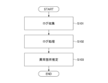
- FIG. 4 is a flowchart showing a processing procedure of the abnormality location estimating device 100.
- FIG. 2 is a diagram illustrating an example of the configuration of a log processing device 200.
- FIG. 2 illustrates an example of a hardware configuration of the apparatus.
- FIG. 1 illustrates an example of a communication network.
- FIG. 6 shows an example of a causal model based on FIG. 5 .
- the anomaly location estimation device 100 assigns a label to each log indicating the factor that generated the log, and for each log with the same assigned label value, estimates the anomaly location using an anomaly location estimation method.
- the device configuration and device operation in this embodiment will be described in detail below.
- Fig. 1 shows a configuration example of an anomaly location estimating device 100 according to this embodiment.
- the anomaly location estimating device 100 includes an observation data collection engine 160, an observation data DB 140, an observation data preprocessing engine 130, a causal model construction engine 110, a causal model inference engine 120, and an output interface 150 for users.
- observation data collection engine 160 the observation data preprocessing engine 130, the causal model construction engine 110, and the causal model inference engine 120 may be referred to as the observation data collection unit 160, the observation data preprocessing unit 130, the causal model construction unit 110, and the causal model inference unit 120, respectively.
- observation data collection engine 160, the observation data preprocessing engine 130, the causal model construction engine 110, and the causal model inference engine 120 may be referred to as the observation data collection circuit 160, the observation data preprocessing circuit 130, the causal model construction circuit 110, and the causal model inference circuit 120, respectively.
- the abnormality location estimation device 100 may also be called a log processing device.
- the observation data collection engine 160 and the observation data pre-processing engine 130 may also be called a log collection unit and a log processing unit, respectively. An overview of the operation of the abnormality location estimation device 100 will be explained following the steps in the flow of FIG. 2.
- the observation data collection engine 160 collects observation data (logs generated by devices, etc.) from a communication network.
- the observation data preprocessing engine 130 determines the label y i to which the generated log belongs, and stores the log in the observation data DB 140 for each set of logs with the same label (z j described later). In other words, logs are stored in the observation data DB 140 for each log that has the same cause of occurrence.
- the observation data collection engine 160 determines the label, which will be described later, and the operator selects one of them in advance.
- two or three of the three methods may be selected, and the operator may check the labels assigned by each method and select the appropriate one.
- the causal model construction engine 110 constructs a causal model using existing methods (methods such as those in Non-Patent Documents 2, 3, and 4).
- the causal model inference engine 120 determines the value of the observation node based on the occurrence status of the logs stored in the observation data DB 140, estimates the abnormality location, and outputs the estimated abnormality location to the output interface 150.
- the output interface 150 displays to the user the location of an anomaly in the communication network and the maximum posterior probability at that time.
- the output interface 150 can add a node to the causal graph and also allow the user to correct any changes in causal relationships that result from this.
- the abnormality location estimation device 100 may be a single device (computer) or may consist of multiple devices.
- the functional unit that estimates the abnormality location using the log processed by the observation data preprocessing engine 130 may be called the "abnormality location estimation unit.”
- observation data DB 140 corresponds to the "anomaly location estimation unit.”
- the abnormality location estimation unit uses a functional unit based on a method (Non-Patent Document 3) that uses a causal model to estimate the abnormality location from observation data at the time of an abnormality, but the abnormality location estimation unit is not limited to using this method.
- observation data collection engine 160 and the observation data pre-processing engine 130 may be configured as a single device, which may be called a log processing device.
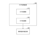
- FIG. 3 shows an example of the configuration of the log processing device 200.
- the log collection device 200 includes a log collection unit 210 and a log processing unit 220.
- FIG. 3 also shows an abnormality location estimation unit 300.
- the log collection unit 210 and the log processing unit 220 correspond to the observation data collection engine 160 and the observation data pre-processing engine 130, respectively.
- the abnormality location estimation unit 300 is located outside the log collection device 200, but the abnormality location estimation unit 300 may be located inside the log collection device 200.
- the log collection unit 210 collects logs from the communication network.
- the log processing unit 220 determines the cause of each log collected by the log collection unit 210, and inputs multiple logs with the same cause to the anomaly location estimation unit 300.
- Any of the devices described in this specification can be realized, for example, by causing a computer to execute a program.
- This computer may be a physical computer or a virtual machine on the cloud.
- the device can be realized by using hardware resources such as a CPU and memory built into a computer to execute a program corresponding to the processing performed by the device.
- the program can be recorded on a computer-readable recording medium (such as a portable memory) and then stored or distributed.
- the program can also be provided via a network such as the Internet or email.
- FIG. 4 is a diagram showing an example of the hardware configuration of the computer.
- the computer in FIG. 4 has a drive device 1000, an auxiliary storage device 1002, a memory device 1003, a CPU 1004, an interface device 1005, a display device 1006, an input device 1007, an output device 1008, etc., all of which are interconnected by a bus BS.
- the program that realizes the processing on the computer is provided by a recording medium 1001, such as a CD-ROM or a memory card.
- a recording medium 1001 storing the program is set in the drive device 1000, the program is installed from the recording medium 1001 via the drive device 1000 into the auxiliary storage device 1002.
- the program does not necessarily have to be installed from the recording medium 1001, but may be downloaded from another computer via a network.
- the auxiliary storage device 1002 stores the installed program as well as necessary files, data, etc.
- the memory device 1003 When an instruction to start a program is received, the memory device 1003 reads out and stores the program from the auxiliary storage device 1002.
- the CPU 1004 realizes the functions related to the device in accordance with the program stored in the memory device 1003.
- the interface device 1005 is used as an interface for connecting to a network.
- the display device 1006 displays a GUI (Graphical User Interface) based on a program.
- the input device 1007 is composed of a keyboard and mouse, buttons, a touch panel, or the like, and is used to input various operational instructions.
- the output device 1008 outputs the results of calculations.
- the operation of the anomaly location estimating device 100 will be described in more detail below. Note that, in this embodiment, it is assumed that a communication network configured with routers is the target, but this is only an example. The technology according to the present invention is applicable regardless of the type of nodes that configure the communication network.
- FIG. 5 shows an example of a communications network from which the observation data collection engine 160 collects observation data.
- this communications network is a network in which routers 1 to 6 are connected as shown.
- routers 1 and 2 are directly connected and are adjacent to each other.
- Routers 1 and 4 are not directly connected and are not adjacent to each other.
- the causal model construction engine 110 constructs the causal model shown in FIG. 6 for the communication network (physical layer network) shown in FIG. 5 based on the knowledge of an expert operator, etc.
- the causal model consists of device nodes that represent the state of each device (router) in the communication network, and observation nodes that represent whether a log (e.g., syslog related to link down) has been generated from the device. In other words, the observation nodes represent the observation results of each device.
- the causal model may also be called a Bayesian network.
- Router 1 which is an equipment node
- Routers 1 and 2 which are observation nodes. This indicates that if an abnormality occurs in Router 1, it may affect the observation data of Router 1 and the observation data of Router 2.
- router 2 which is an equipment node, is connected to routers 1, 2, 3, and 6, which are observation nodes. This indicates that if an abnormality occurs in router 2, it may affect the observation data of routers 1, 2, 3, and 6.
- observation data preprocessing engine 130 assigns a label indicating the cause of the log generation to each log collected by the observation data collection engine 160, and stores the labeled logs in the observation data DB 140.
- the causal model inference engine 120 performs anomaly location estimation for each log with the same assigned label value. The operation of the observation data preprocessing engine 130 will be described in more detail below.
- logs generated between time t and t+ ⁇ are denoted by x 1 , ..., x N.
- ⁇ is a time width for executing the anomaly location estimation process, which is determined in advance by any method. If it is desired to obtain an estimation result within one minute after the occurrence of a fault, ⁇ is set to 30 seconds, for example. N is the number of logs generated.
- x 1 , ..., x N are input to an abnormality part estimation unit to perform abnormality part processing.
- the estimation accuracy decreases due to the above-mentioned problem.
- the value of yi is a positive integer value from 1 to M, where M is an arbitrary value.
- the label yi represents the cause of the log occurrence, such as a failure occurring in the communication network, construction work, or user-caused events, and M is the total number of types of these causes.
- 1 represents a log caused by failure A
- 2 represents a log caused by failure B.
- the observation data pre-processing engine 130 analyzes these logs and finds that x1 , x2 , and x4 occurred due to failure A, and x3 and x5 occurred due to failure B, then y1 , y2 , and y4 are set to 1, and y3 and y5 are set to 2.
- the observation data preprocessing engine 130 inputs z j to the anomaly location estimation unit.
- logs with the same value of y i that is, logs with the same failure cause that generated the logs, are input to the anomaly location estimation unit.
- the observation data pre-processing engine 130 stores z j in the observation data DB 140. This means that the logs are stored in the observation data DB 140 for each log that has the same failure cause that caused the log.
- the label determination method is not limited to a specific method, but in this embodiment, the following three examples, determination method example 1 to 3, will be described. Note that any two of determination method example 1 to 3, or all of determination method example 1 to 3, may be combined to determine the log generation cause.
- Decision method example 1 In the determination method example 1, it is assumed that the events that cause the problems in a communication network and the patterns of log occurrences due to the problems are known. In this case, the observation data preprocessing engine 130 creates rules (e.g., cause 1 causes device A to generate log B, etc.) in sequence using the known problems and the patterns of log occurrences, and assigns each rule from 1 to M.
- rules e.g., cause 1 causes device A to generate log B, etc.
- the observation data preprocessing engine 130 When the observation data preprocessing engine 130 acquires an occurring log x i , it checks which rule the log applies to and determines the value of y i as a value representing the rule that applies. In this case, M may be set to the total number of rules.
- Determination method example 2 In the determination method example 2, the observation data preprocessing engine 130 heuristically determines the value of yi using external information that determines the cause of the log generation. Here, it is assumed that the observation data preprocessing engine 130 is capable of acquiring the external information necessary to determine the value of yi , for example, periodically or as needed.
- observation data pre-processing engine 130 determines that construction work was carried out in the communication network from time t to t+ ⁇ , it determines that the log x i generated during that time is likely to be caused by the construction work, and sets a value representing the construction work to y i . Also, if the observation data pre-processing engine 130 determines that logs due to a fault C are constantly generated, it sets the label y i for the generated log x i to a value representing the fault C.
- the observation data preprocessing engine 130 detects that a log x i has occurred in a device that the user can operate, it sets the value of the label y i to a value indicating the user's cause, and determines that the other logs are caused by a fault that occurred between time t and t+ ⁇ , and sets the value of the label y i to a value indicating that fault.
- the value of the label yi can be determined for each log xi .
- values starting from 1 are assigned to the causes of construction, failures, and user operations that occurred in the past, and the value of M is increased each time the number of causes increases.
- Determination method example 3 In example determination method 3, the observational data pre-processing engine 130 uses an algorithm to determine the label values from the data.
- the method (algorithm) for determining the label value from the data is not limited to a specific method, but for example, a known method disclosed in Reference 1 (WO2022/259307A1) can be used. This method is a method for clustering alarms by cause.
- the observation data preprocessing engine 130 clusters logs generated from time t to t+ ⁇ , obtains a cluster value indicating which cluster each log belongs to, and uses the obtained cluster value as the value of y i for the log belonging to that cluster. This makes it possible to assign a label to the log for each factor. In this case, the maximum value of the cluster value can be used as the value of M. Note that a method other than the method disclosed in Reference 1 may be used as a method for classifying the factors of the logs by clustering.
- the processes themselves performed by the causal model construction engine 110 and the causal model inference engine 120 are existing technologies.
- the method of constructing a causal model by the causal model construction engine 110 is as described with reference to Fig. 5 and Fig. 6, and for example, a causal model is constructed from the physical (or logical) connection relationships of devices.
- logs are stored in the observation data DB 140 for each log with the same failure cause.
- the causal model inference engine 120 uses a causal model to infer an anomaly location for each log with the same failure cause (log with the same value of yi ).
- the node values are defined as follows:
- an equipment node is denoted as a i
- an observation node is denoted as b i , i ⁇ (1, . . . N), where N is the number of equipment.
- Each ai takes a value of 0 (normal state) or 1 (abnormal state). It is possible for ai to take multiple values, not just 0 or 1, and in that case, the minimum value is the normal state, the maximum value is the abnormal state, and a value c between them is defined as a value that indicates abnormality at the rate of "c/(maximum value-minimum value)".
- Each b i takes a value of 0 or 1, where 1 indicates that a log occurred at the i-th router. Note that instead of the binary values of 0 and 1, it is also possible for it to take multiple values of 3 or more, in which case the value is defined as the number of logs that occurred at the i-th router.
- the input values to the above causal model can be determined (calculated) by the causal model inference engine 120 from the logs read from the observation data DB 140.
- the inference itself using the causal model is the same as the method in Non-Patent Document 3, and inference is performed by defining the prior probability P(a i ) and the conditional probability P(b j
- the observation data pre-processing engine 130 assigns a label to each log indicating the cause of the log's occurrence, and the anomaly point estimation unit estimates the anomaly point for each log that has the same assigned label value. This makes it possible to improve the accuracy of estimating anomalies in a communication network.
- Additional Notes Memory, at least one processor coupled to the memory; Including, The processor, Collect logs from communication networks, The log processing device determines the cause of each collected log, and inputs multiple logs having the same cause to an anomaly location estimation unit.
- the log processing device assigns a label indicating a cause of occurrence to each collected log, and inputs a plurality of logs having the same assigned label value to the abnormality portion estimation unit.
- Additional Note 3 3.
- a log processing method executed by a log processing device comprising: A log collection step of collecting logs from a communication network; a log processing step of determining a cause of occurrence of each log collected in the log collecting step, and inputting a plurality of logs having the same cause of occurrence to an abnormality part estimating unit.
- a non-transitory storage medium storing a program for causing a computer to function as a log collection unit and a log processing unit in the log processing device according to any one of claims 1 to 5.
- Anomaly location estimation device 110 Causal model construction engine 120 Causal model inference engine 130 Observation data pre-processing engine 140 Observation data DB 150 Output interface 160 Observation data collection engine 200 Log collection device 210 Log collection unit 220 Log processing unit 300 Anomaly location estimation unit 1000 Drive device 1001 Recording medium 1002 Auxiliary storage device 1003 Memory device 1004 CPU 1005 Interface device 1006 Display device 1007 Input device 1008 Output device
Landscapes
- Engineering & Computer Science (AREA)
- Computer Networks & Wireless Communication (AREA)
- Signal Processing (AREA)
- Debugging And Monitoring (AREA)
Abstract
Ce dispositif de traitement de journal comprend : une unité de collecte de journaux qui collecte des journaux à partir d'un réseau de communication ; et une unité de traitement de journal qui détermine des facteurs d'occurrence des journaux respectifs collectés par l'unité de collecte de journaux, et entre une pluralité de journaux présentant le même facteur d'occurrence dans une unité d'estimation d'emplacement anomal.
Priority Applications (1)
| Application Number | Priority Date | Filing Date | Title |
|---|---|---|---|
| PCT/JP2023/030049 WO2025041236A1 (fr) | 2023-08-21 | 2023-08-21 | Dispositif de traitement de journal, procédé de traitement de journal et programme |
Applications Claiming Priority (1)
| Application Number | Priority Date | Filing Date | Title |
|---|---|---|---|
| PCT/JP2023/030049 WO2025041236A1 (fr) | 2023-08-21 | 2023-08-21 | Dispositif de traitement de journal, procédé de traitement de journal et programme |
Publications (1)
| Publication Number | Publication Date |
|---|---|
| WO2025041236A1 true WO2025041236A1 (fr) | 2025-02-27 |
Family
ID=94731846
Family Applications (1)
| Application Number | Title | Priority Date | Filing Date |
|---|---|---|---|
| PCT/JP2023/030049 Pending WO2025041236A1 (fr) | 2023-08-21 | 2023-08-21 | Dispositif de traitement de journal, procédé de traitement de journal et programme |
Country Status (1)
| Country | Link |
|---|---|
| WO (1) | WO2025041236A1 (fr) |
Citations (7)
| Publication number | Priority date | Publication date | Assignee | Title |
|---|---|---|---|---|
| WO2017154844A1 (fr) * | 2016-03-07 | 2017-09-14 | 日本電信電話株式会社 | Dispositif d'analyse, procédé d'analyse et programme d'analyse |
| JP2018124697A (ja) * | 2017-01-31 | 2018-08-09 | オムロン株式会社 | 情報処理装置、情報処理プログラムおよび情報処理方法 |
| US10992557B1 (en) * | 2018-11-09 | 2021-04-27 | Innovium, Inc. | Traffic analyzer for network device |
| JP2022061676A (ja) * | 2020-10-07 | 2022-04-19 | エヌ・ティ・ティ・コムウェア株式会社 | 学習装置、推定装置、シーケンス推定システムおよび方法、プログラム |
| JP2022130491A (ja) * | 2019-10-31 | 2022-09-06 | アシュラント,インコーポレーテッド | 独立したコンピューティングリソースを管理し、および同期させるためのシステム、方法、装置、およびコンピュータプログラム製品 |
| JP2022161102A (ja) * | 2021-04-08 | 2022-10-21 | 株式会社日立製作所 | 分散システム、及びデータ転送方法 |
| JP2023004324A (ja) * | 2021-06-25 | 2023-01-17 | キヤノン株式会社 | 画像形成装置、画像形成装置の制御方法、及びプログラム |
-
2023
- 2023-08-21 WO PCT/JP2023/030049 patent/WO2025041236A1/fr active Pending
Patent Citations (7)
| Publication number | Priority date | Publication date | Assignee | Title |
|---|---|---|---|---|
| WO2017154844A1 (fr) * | 2016-03-07 | 2017-09-14 | 日本電信電話株式会社 | Dispositif d'analyse, procédé d'analyse et programme d'analyse |
| JP2018124697A (ja) * | 2017-01-31 | 2018-08-09 | オムロン株式会社 | 情報処理装置、情報処理プログラムおよび情報処理方法 |
| US10992557B1 (en) * | 2018-11-09 | 2021-04-27 | Innovium, Inc. | Traffic analyzer for network device |
| JP2022130491A (ja) * | 2019-10-31 | 2022-09-06 | アシュラント,インコーポレーテッド | 独立したコンピューティングリソースを管理し、および同期させるためのシステム、方法、装置、およびコンピュータプログラム製品 |
| JP2022061676A (ja) * | 2020-10-07 | 2022-04-19 | エヌ・ティ・ティ・コムウェア株式会社 | 学習装置、推定装置、シーケンス推定システムおよび方法、プログラム |
| JP2022161102A (ja) * | 2021-04-08 | 2022-10-21 | 株式会社日立製作所 | 分散システム、及びデータ転送方法 |
| JP2023004324A (ja) * | 2021-06-25 | 2023-01-17 | キヤノン株式会社 | 画像形成装置、画像形成装置の制御方法、及びプログラム |
Similar Documents
| Publication | Publication Date | Title |
|---|---|---|
| US7113988B2 (en) | Proactive on-line diagnostics in a manageable network | |
| CN104796273B (zh) | 一种网络故障根源诊断的方法和装置 | |
| KR100714157B1 (ko) | 컴퓨터 기반 방법, 컴퓨터 판독 가능 기록 매체 및 데이터 처리 시스템 | |
| US8583779B2 (en) | Root cause analysis approach with candidate elimination using network virtualization | |
| US8656219B2 (en) | System and method for determination of the root cause of an overall failure of a business application service | |
| US7725774B2 (en) | Methods, systems, and media to correlate errors associated with a cluster | |
| CN113328872A (zh) | 故障修复方法、装置和存储介质 | |
| US20090063902A1 (en) | Preliminary Classification of Events to Facilitate Cause-Based Analysis | |
| US10728085B1 (en) | Model-based network management | |
| CN118520405B (zh) | 基于人工智能的云数据平台综合服务管理系统及方法 | |
| US8156319B2 (en) | Self-restarting network devices | |
| CN101507185A (zh) | 使用贝叶斯网络的电信网络中的故障定位 | |
| CN113973042A (zh) | 用于网络问题的根本原因分析的方法和系统 | |
| CN107210927A (zh) | 协议处理中的异常检测 | |
| JP3579834B2 (ja) | 管理可能なネットワークにおける事前対策オンライン診断 | |
| WO2025124097A1 (fr) | Procédé de localisation de défaillance et appareil | |
| JP6954379B2 (ja) | 異常箇所特定装置、異常箇所特定方法及びプログラム | |
| CN118780665A (zh) | 设备运维质量分析方法、装置、电子设备及存储介质 | |
| JP7414135B2 (ja) | モデル構築装置、推定装置、モデル構築方法、推定方法及びプログラム | |
| JP2018124829A (ja) | 状態判定装置、状態判定方法及びプログラム | |
| Matsuo et al. | Root-cause diagnosis for rare failures using bayesian network with dynamic modification | |
| US20080195728A1 (en) | Network Subscriber Experience Modeling | |
| WO2025041236A1 (fr) | Dispositif de traitement de journal, procédé de traitement de journal et programme | |
| JPWO2013111317A1 (ja) | 情報処理方法、装置及びプログラム | |
| WO2024252479A1 (fr) | Dispositif de traitement de journal, procédé de traitement de journal et programme |
Legal Events
| Date | Code | Title | Description |
|---|---|---|---|
| 121 | Ep: the epo has been informed by wipo that ep was designated in this application |
Ref document number: 23949697 Country of ref document: EP Kind code of ref document: A1 |
|
| ENP | Entry into the national phase |
Ref document number: 2025541192 Country of ref document: JP Kind code of ref document: A |
|
| WWE | Wipo information: entry into national phase |
Ref document number: 2025541192 Country of ref document: JP |
|
| NENP | Non-entry into the national phase |
Ref country code: DE |