WO2025041226A1 - Système de gestion d'installation, dispositif de gestion d'installation, procédé de gestion d'installation et programme de gestion d'installation - Google Patents
Système de gestion d'installation, dispositif de gestion d'installation, procédé de gestion d'installation et programme de gestion d'installation Download PDFInfo
- Publication number
- WO2025041226A1 WO2025041226A1 PCT/JP2023/030003 JP2023030003W WO2025041226A1 WO 2025041226 A1 WO2025041226 A1 WO 2025041226A1 JP 2023030003 W JP2023030003 W JP 2023030003W WO 2025041226 A1 WO2025041226 A1 WO 2025041226A1
- Authority
- WO
- WIPO (PCT)
- Prior art keywords
- accident
- equipment
- facility management
- damage situation
- test
- Prior art date
- Legal status (The legal status is an assumption and is not a legal conclusion. Google has not performed a legal analysis and makes no representation as to the accuracy of the status listed.)
- Pending
Links
Images


Classifications
-
- G—PHYSICS
- G05—CONTROLLING; REGULATING
- G05B—CONTROL OR REGULATING SYSTEMS IN GENERAL; FUNCTIONAL ELEMENTS OF SUCH SYSTEMS; MONITORING OR TESTING ARRANGEMENTS FOR SUCH SYSTEMS OR ELEMENTS
- G05B23/00—Testing or monitoring of control systems or parts thereof
- G05B23/02—Electric testing or monitoring
Definitions
- This disclosure relates to a facility management system, a facility management device, a facility management method, and a facility management program.
- Patent Document 1 discloses a technology that provides map data used by a robot to move autonomously in places where radio waves from satellites cannot be received.
- a transmitter transmits transmitter identification information that identifies the transmitter itself.
- the robot transmits the detected transmitter identification information to a map management device, and receives map data corresponding to the transmitter identification information from the map management device.
- the robot controls the drive of the drive unit that moves the robot based on an autonomous action plan created using the received map data.
- the map management device reads out the map data corresponding to the transmitter identification information notified by the robot from a memory unit and transmits it.
- Patent Document 1 allows the robot to determine its own position, but does not allow it to grasp the extent of damage in the surrounding area.
- This disclosure has been made to solve the problems described above, and aims to provide technology that is useful for administrators to manage the surrounding damage situation caused by accidents involving autonomous mobile objects.
- the facility management system disclosed herein is an facility management system including a mobile control device that controls an autonomous mobile body, a plurality of facilities arranged within an area, and a facility management device that communicates with the mobile control device and the plurality of facilities and estimates the damage status of an accident that occurs to an autonomous mobile body within the area, the mobile control device is configured to transmit the location of the accident to the facility management device when an accident occurs to the autonomous mobile body, the facility management device has a surrounding facility identification unit that acquires the location of the accident from the mobile control device, identifies surrounding facilities among the plurality of facilities that are located around the location of the accident, and transmits a test command to the surrounding facilities, and a damage status estimation unit that acquires test results from the surrounding facilities and estimates the damage status around the location of the accident based on the test results, and the surrounding facilities are configured to receive test commands from the facility management device, execute tests according to the test commands, and transmit the test results to the facility management device as test results.
- the facility management device disclosed herein is an facility management device that communicates with a mobile control device that controls an autonomous mobile body and multiple facilities located within an area, and estimates the damage situation of an accident that occurs to an autonomous mobile body within the area, and includes a peripheral facility identification unit that acquires the accident location transmitted from the mobile control device when an accident occurs to the autonomous mobile body, identifies peripheral facilities among the multiple facilities that are located around the accident location, and transmits test commands to the peripheral facilities, and a damage situation estimation unit that acquires test results from each of the peripheral facilities that perform tests in accordance with the test commands, and estimates the damage situation around the accident location based on the test results.
- the facility management method disclosed herein is a facility management method that causes a computer to estimate the damage situation of an accident involving an autonomous moving body that occurs in an area where multiple facilities are located, and includes the steps of acquiring the location of the accident when an accident occurs to an autonomous moving body, identifying peripheral facilities among the multiple facilities that are located around the location of the accident, running tests on the peripheral facilities, and estimating the damage situation around the location of the accident based on the test results.
- the facility management program disclosed herein is a facility management program that causes a computer to estimate the damage situation in the event of an accident involving an autonomous moving body that occurs in an area where multiple pieces of equipment are located, and is configured to cause the computer to acquire the location of the accident when an accident occurs to an autonomous moving body, identify peripheral equipment among the multiple pieces of equipment that is located in the vicinity of the location of the accident, run tests on the peripheral equipment, and estimate the damage situation in the vicinity of the location of the accident based on the test results.
- the facility management program disclosed herein is a facility management program that communicates with a mobile control device that controls an autonomous mobile body and multiple pieces of equipment located within an area, and causes a computer to execute the following operations: acquire the location of the accident transmitted from the mobile control device when an accident occurs to an autonomous mobile body; identify peripheral equipment among the multiple pieces of equipment that is located around the location of the accident; transmit test commands to the peripheral equipment; acquire test results from each piece of peripheral equipment that performs tests in accordance with the test commands; and estimate the damage situation around the location of the accident based on the test results.
- This disclosure makes it possible to provide technology that is advantageous for administrators to manage the surrounding damage situation caused by accidents involving autonomous moving objects.
- FIG. 1 is a diagram for explaining an overview of a facility management system according to a first embodiment
- 10 is a pattern diagram showing an example of peripheral equipment identified by the peripheral equipment identification process
- FIG. FIG. 11 is a diagram showing an example of damage estimation data.
- 1 is a block diagram showing a configuration of a facility management system according to a first embodiment
- 4 is a flowchart of a process executed in the facility management system according to the first embodiment.
- FIG. 13 is a diagram illustrating a modification of the hardware resources of the equipment management device.
- FIG. 13 is a diagram showing an example of damage estimation data according to a modified example.
- FIG. 11 is a diagram showing a specific example of a damage situation estimated in the damage situation estimation process.
- FIG. 13 is a flowchart of a process executed in a facility management system according to a second embodiment. 13 is a flowchart of a process executed in a facility management system according to a third embodiment. 11 is a diagram for explaining an additional search area specification process. FIG. FIG. 13 is a block diagram showing the configuration of a facility management system according to a fourth embodiment. FIG. 11 is a diagram showing an example of damage estimation data.
- FIG. 1 is a diagram for explaining an overview of the facility management system according to the first embodiment.
- the facility management system 100 of this embodiment is a system that, when an accident occurs in an autonomous mobile object traveling within an area such as a facility, determines the damage status of facility equipment around the accident site and notifies the manager.
- Examples of the "accident” here include contact or collision of the autonomous mobile object with an obstacle, a fall of the autonomous mobile object, and disasters such as fires caused by these.
- Examples of the "facility equipment” include elevators and other lifts installed within the area, automatic doors, monitors such as information boards or advertising displays, circulators, environmental sensors, air conditioners, lighting, traffic lights, street lights, other installed robots, and the like.
- the facility management system 100 of the first embodiment is applied to a managed area of a facility or the like.
- the facility is, for example, an indoor facility, an outdoor facility, or a combination of these.
- the facility is, for example, made up of one or more buildings.
- the facility may be, for example, part of a building.
- the facility management system 100 includes a facility management device 10, a robot 8, a robot management server 40, one or more facility devices 50, and an administrator terminal 60.
- the robot 8 is an autonomous mobile object capable of autonomously traveling within an area while determining its own position. There is no limitation on the method by which the robot 8 determines its own position.
- the robot 8 detects its own position and orientation using a position sensor.
- the position sensor includes, for example, a GPS (Global Positioning System) sensor.
- the GPS sensor receives signals transmitted from multiple GPS satellites and calculates the position and orientation of the robot 8 based on the received signals.
- the position sensor may perform a well-known self-position estimation process (localization) to improve the accuracy of the current position of the robot 8.
- the robot 8 may be configured to detect its own position within the facility using a positioning device using short-range wireless communication such as UWB (Ultra Wide Band).
- UWB Ultra Wide Band
- the positioning device includes a UWB terminal that transmits UWB signals and a receive-only tag that receives UWB signals.
- Multiple UWB terminals of the positioning device are installed at intervals within the facility.
- the receive-only tag is installed on the robot 8.
- short-range wireless communication can be performed using a beacon device that uses Bluetooth (registered trademark) or the like, or a device that uses RFID, in addition to UWB.
- the robot 8 operates under the control of a robot management server 40, which serves as a mobile object control device. There are no limitations on the type, use, or operation control of the robot 8.
- the robot 8 communicates with the robot management server 40 via a communication network 6, such as wireless.
- the robot management server 40 is installed, for example, within a facility.
- the robot management server 40 communicates with the facility management device 10 via a communication network 6, such as the Internet.
- the equipment management device 10 is a device that estimates the damage status of one or more pieces of equipment 50 around the site of an accident when an accident or other malfunction occurs to a robot 8 within the area.
- the equipment management device 10 communicates with one or more pieces of equipment 50 via a communication network 6 such as the Internet.
- the equipment management device 10 also communicates with an administrator terminal 60 via the communication network 6.
- the administrator terminal 60 is a terminal managed by an administrator, and is a portable terminal device equipped with wireless communication functions, such as a smartphone.
- the administrator terminal 60 is connected to a communication network 6, such as the Internet.
- the administrator terminal 60 is equipped with an output device 62 that outputs information to the administrator.
- Examples of the output device 62 include a display device and a speaker.
- the display device may be configured as a touch panel display.
- the robot 8 in which the accident occurred transmits a fault occurrence notification, including information about the occurrence of the accident, and robot position information, including information about the location where the accident occurred, to the robot management server 40.
- the robot management server 40 transmits the received fault occurrence notification and robot position information to the equipment management device 10.
- the equipment management device 10 which has received a notification of a fault occurrence, identifies one or more pieces of equipment 50 that are located near the location where the accident occurred. This process is hereinafter referred to as the "surrounding equipment identification process.”
- the "surrounding area” here refers to a predetermined range that is likely to be affected by damage caused by an accident involving the robot 8.
- the equipment management system 100 holds map data in which the location information of one or more pieces of equipment 50 is associated with map information within the area. In the surrounding equipment identification process, the equipment management device 10 identifies and lists the surrounding equipment by referring to the map data.
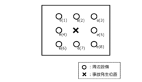
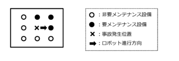
- FIG. 2 is a pattern diagram showing an example of peripheral equipment identified by the peripheral equipment identification process.
- the arrangement pattern here is a pattern that specifies the relative positions of multiple peripheral equipment with respect to the accident location. There are no limitations on the arrangement pattern.
- FIG. 2 shows an example of an arrangement pattern in which peripheral equipment is aligned at eight points in front of, behind, to the left, to the right, in front of, in front of, in front of, in front of, in front of, in rear of, and in rear of the accident location.
- the arrangement pattern may be, for example, a pattern in which the equipment is aligned on a circumference surrounding the accident location. There are no limitations on the method for approximating the positions of the equipment 50 to the arrangement of the specified arrangement pattern.
- the equipment management device 10 sends a test command to each identified peripheral equipment e(k). This process is hereinafter referred to as the "test process".
- the test command includes a communication test command to instruct a test of the communication state, and an operation test command to instruct a test of the operation state.
- the equipment management device 10 first sends a communication test command to each identified peripheral equipment e(k). Then, the equipment management device 10 receives the communication test results sent from each peripheral equipment e(k). If the received communication test results are normal, the equipment management device 10 sends an operation test command to each identified peripheral equipment e(k). Then, the equipment management device 10 receives the operation test results sent from each peripheral equipment e(k).
- the equipment management device 10 estimates the damage situation around the location where the failure occurred based on the received test results. This process is hereinafter referred to as the "damage situation estimation process".
- damage estimation data is referenced.
- FIG. 3 is a diagram showing an example of damage estimation data.
- FIG. 3 illustrates the layout of each peripheral equipment e(k) existing around the accident occurrence location, and multiple types of equipment failure patterns associated with attributes of whether each peripheral equipment e(k) is maintenance-required equipment that requires maintenance or non-maintenance-required equipment that does not require maintenance.
- (A) in the figure shows a pattern in which damage is concentrated on one side of the accident occurrence location.
- Pattern (A) can be estimated as a damage situation in which, for example, the robot 8 stops after a collision without falling over.
- (B) in the figure shows a pattern in which damage extends to two sides of the accident occurrence location.
- Pattern (B) can be estimated as a damage situation in which, for example, the robot 8 falls over after a collision.
- (C) in the figure shows a pattern in which damage extends to all sides of the accident occurrence location.
- Pattern (C) can be estimated to be a damage situation in which, for example, an accident involving robot 8 has caused a fire to break out in the surrounding area.
- the damage estimation data corresponds to information on the estimated damage situation for each equipment failure pattern.
- the equipment management device 10 generates damage situation information that estimates the damage situation by comparing the test results of the surrounding equipment with the damage estimation data.
- the "damage situation information" generated here includes whether or not maintenance is required for each piece of surrounding equipment, the state of the robot 8, and the accident situation.
- the accident situation includes whether or not the robot 8 has fallen, the extent of the damage, etc.
- the damage situation information is transmitted to the administrator terminal 60 via the communication network 6.
- the administrator terminal 60 outputs the received damage status information from the output device 62 to notify the administrator.
- notification means by the output device 62 include display output on a screen, audio output from a speaker, etc.
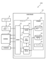
- the facility management system 100 includes the above-mentioned facility management device 10, a robot 8, a robot management server 40, one or more facility devices 50, and an administrator terminal 60.
- the facility management device 10 is a microcomputer that includes at least one processor 20 and at least one storage device 30.
- the facility management device 10 is also called an information processing device.
- the storage device 30 stores map data 32, damage estimation data 34, and an equipment management program 36.
- the map data 32 includes map information within the area, map information inside the building, and position coordinate information for each piece of equipment 50.
- the damage estimation data 34 stores the multiple types of equipment failure patterns described above.
- the map data 32 and damage estimation data 34 may be stored in a server capable of communicating with the equipment management device 10, such as the robot management server 40 or a cloud server.
- the processor 20 includes a CPU (Central Processing Unit).
- the processor 20 reads and executes the equipment management program 36 to realize various functions of the equipment management device 10.
- the equipment management program 36 may be recorded on a computer-readable recording medium.
- the equipment management device 10 has the following functional blocks: a communication unit 22, a surrounding equipment identification unit 24, and a damage situation estimation unit 26.
- the communication unit 22 is a functional block for communicating with external devices.
- the communication unit 22 communicates with the robot management server 40, the equipment 50, and the manager terminal 60 via the communication network 6.
- the peripheral equipment identification unit 24 is a functional block for performing peripheral equipment identification processing.
- the damage situation estimation unit 26 is a functional block for performing damage situation estimation processing. Below, the specific processing executed in the equipment management device 10 will be explained with reference to a flowchart.
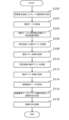
- Fig. 5 is a flowchart of processing executed in the facility management system according to the first embodiment.
- the routine shown in Fig. 5 is executed by the processor 20 of the facility management device 10 executing the facility management program 36 stored in the storage device 30.
- This routine also represents a part of a facility management method for estimating the damage situation caused by an accident involving the robot 8 in the facility management system 100.
- step S100 of the routine shown in FIG. 5 the communication unit 22 receives a fault occurrence notification and robot position information from the robot management server 40.
- the received fault occurrence notification and robot position information are sent to the peripheral equipment identification unit 24.
- step S102 the process proceeds to step S102.
- step S102 the surrounding facility identification unit 24 acquires map data stored in the storage device 30. After the processing of step S102 is performed, the process proceeds to step S104.
- step S104 the surrounding equipment identification unit 24 executes a surrounding equipment identification process to identify surrounding equipment from the map data and the robot position information.
- the surrounding equipment identification unit 24 refers to the map data to identify each piece of surrounding equipment e(k) located in each section R(k) surrounding the accident location included in the robot position information from among the equipment 50.
- step S106 the peripheral equipment identification unit 24 executes a test process to perform a communication test with each identified peripheral equipment e(k). Specifically, the peripheral equipment identification unit 24 transmits a communication test command from the communication unit 22 to each peripheral equipment e(k) to determine whether the communication state is good. After the process of step S106 is performed, the process proceeds to step S108.
- step S108 the communication unit 22 receives the communication test results, including the results of the communication tests carried out in each peripheral equipment e(k), from each peripheral equipment e(k) and sends them to the damage situation estimation unit 26. After the processing of step S108 is performed, the process proceeds to step S110.
- step S110 the peripheral equipment identification unit 24 executes a test process to perform an operation test with each identified peripheral equipment e(k). Specifically, the peripheral equipment identification unit 24 transmits an operation test command from the communication unit 22 to each peripheral equipment e(k) to determine whether the operation of each peripheral equipment e(k) is normal. After the process of step S110 is performed, the process proceeds to step S112.
- step S112 the communication unit 22 receives operational test results, including the results of the operational tests carried out in each peripheral facility e(k), from each peripheral facility e(k) and sends them to the damage situation estimation unit 26. After the processing in step S112 is performed, the process proceeds to step S114.
- step S114 the damage situation estimation unit 26 acquires the damage estimation data stored in the storage device 30. After the processing of step S114 is performed, the process proceeds to step S116.
- step S116 the damage situation estimation unit 26 performs a damage situation estimation process. Specifically, the damage situation estimation unit 26 compares the communication test results acquired in step S108 and the operation test results acquired in step S110 with the damage estimation data acquired in step S114.
- peripheral equipment e(k) identified in step S104 peripheral equipment with good communication test results and good operation test results is associated as equipment not requiring maintenance, and peripheral equipment with at least one of the communication test results and the operation test results being poor is associated as equipment requiring maintenance.
- the damage situation estimation unit 26 compares the equipment failure pattern formed by each peripheral equipment e(k) with the equipment failure pattern in the damage estimation data, and determines the damage situation of the most similar equipment failure pattern as the estimated damage situation. Then, the damage situation estimation unit 26 generates damage situation information including the estimated damage situation and whether or not each peripheral equipment e(k) requires maintenance.
- step S118 the damage situation estimation unit 26 transmits the damage situation information from the communication unit 22 to the administrator terminal 60.
- the administrator terminal 60 notifies the administrator of the received damage situation information.
- the facility management system 100 of the first embodiment may adopt the following modified aspects. Note that these modified aspects may also be applied to facility management systems of other embodiments described later.
- Robot management server 40 Some or all of the functions of the robot management server 40 may be realized as functions of the processor 20 of the facility management device 10. Some or all of the functions of the robot management server 40 may be mounted on a device provided outside the facility. Some or all of the functions of the robot management server 40 may be implemented across multiple pieces of hardware. In this case, each piece of hardware is connected to each other so that they can communicate with each other through a communication network 6 such as the Internet. Some or all of the functions of the robot management server 40 may be implemented by processing and storage resources on a cloud service.
- FIG. 6 is a diagram showing a modified example of the hardware resources of the equipment management device 10.
- the equipment management device 10 includes, for example, a processor 20, a storage device 30, and a processing circuit 72 including dedicated hardware 70.
- FIG. 6 shows an example in which some of the functions of the equipment management device 10 are realized by the dedicated hardware 70. All of the functions of the equipment management device 10 may be realized by the dedicated hardware 70.
- the dedicated hardware 70 a single circuit, a composite circuit, a programmed processor, a parallel programmed processor, an ASIC, an FPGA, or a combination of these can be adopted.
- the role of the storage device 30 may be played by a cloud or the like independent of the facility management device 10.
- the role of the communication unit 22 may be played by a data platform or the like independent of the facility management device 10.
- the damage situation estimation unit 26 may be configured to estimate the damage situation more accurately using information on the traveling direction of the robot 8.
- the robot 8 detects its traveling direction from the orientation detected by the position sensor.
- the robot 8 detects its traveling direction from the movement trajectory of its own position detected by the position sensor.
- the robot 8 transmits a fault occurrence notification and robot position information including information on the accident location and the traveling direction of the robot 8 to the robot management server 40.
- the robot management server 40 transmits the received fault occurrence notification and robot position information to the equipment management device 10.
- the damage situation estimation unit 26 associates each peripheral equipment e(k) with an attribute of whether it is maintenance-requiring equipment or maintenance-requiring equipment, and associates the attribute of the traveling direction of the robot 8 with the accident occurrence position.
- FIG. 7 is a diagram showing an example of damage estimation data of the modified example.
- FIG. 7 illustrates an example of an equipment failure pattern in which the attribute of whether each peripheral equipment e(k) existing around the accident occurrence position is maintenance-requiring equipment that requires maintenance or maintenance-free equipment that does not require maintenance is associated with the attribute of the traveling direction of the robot at the accident occurrence position.
- the equipment failure pattern of FIG. 7 shows a pattern in which damage occurs on two sides of the accident occurrence position, including the traveling direction.
- Such a pattern can be estimated as a damage situation in which, for example, the robot 8 collides and then falls to the left of the traveling direction.
- the storage device 30 stores damage estimation data 34 including multiple equipment failure patterns associated with the attribute of the traveling direction as shown in FIG. 7.
- the equipment management device 10 generates damage situation information that estimates the damage situation by comparing the test results of the peripheral equipment with the damage estimation data 34.
- This modified damage situation estimation process makes it possible to more accurately estimate the damage situation caused by an accident involving the robot 8.
- the test process may be either a communication test or an operation test.
- the peripheral equipment specifying unit 24 transmits either a communication test command or an operation test command to each peripheral equipment e(k).
- Damage Estimation Data 34 It is considered that the extent of damage caused by an accident may differ depending on the specifications of the robot 8. Therefore, the damage estimation data 34 may be set individually according to the specifications of the robot 8.
- Embodiment 2 In the second embodiment, differences from the example disclosed in the first embodiment will be described in particular detail. For features not described in the second embodiment, any of the features of the example disclosed in the first embodiment may be adopted.
- the facility management system 100 of the second embodiment is characterized by the process of identifying surrounding facilities in units of pre-defined zone areas and judging the damage status.
- Map data 32 includes map information within the area, map information for the interior of the building, and position coordinate information for each piece of equipment 50.
- the map information includes division information that divides the area into multiple division areas. There are no limitations on the shape, size, or division method of each division area. For example, the map information includes division information that divides the area into a grid pattern.
- the equipment management device 10 refers to the map data to identify the area of the equipment 50 that includes the location where the accident occurred as the accident occurrence area, and identifies the equipment 50 within the identified accident occurrence area as the surrounding equipment e(k).
- the equipment management device 10 calculates the proportion of defective equipment that was found to be defective in the test process results among the surrounding equipment e(k) within the accident occurrence area. The equipment management device 10 then estimates the damage situation according to the calculated proportion. Typically, when the proportion of defective equipment is large, the equipment management device 10 determines that the scale of damage is greater than when the proportion is small.
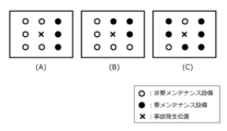
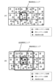
- FIG. 8 shows a specific example of the damage situation estimated in the damage situation estimation process.
- map information including partition information in which the area is divided into a grid shows several examples of patterns in which each piece of surrounding equipment e(k) in the accident area is associated with an attribute indicating whether it is maintenance-requiring equipment that requires maintenance or non-maintenance-requiring equipment that does not require maintenance.
- (A) in the figure shows a pattern in which the proportion of defective equipment determined to be maintenance-requiring equipment among the surrounding equipment e(k) in the accident area is small. Since the damage to the surrounding equipment e(k) in the accident area is relatively small in pattern (A), it can be estimated that the damage situation is one in which a small-scale accident has occurred.
- Pattern (B) in the figure shows a pattern in which the proportion of defective equipment determined to require maintenance is high among the surrounding equipment e(k) within the accident area.
- Pattern (A) can be estimated as a damage situation in which a large-scale accident has occurred, since the damage to the surrounding equipment e(k) within the accident area is relatively large.
- the processing of the facility management system 100 according to the second embodiment makes it possible to identify areas where damage may occur due to an accident, and then estimate the scale of damage within the identified areas.
- Fig. 9 is a flowchart of processing executed in the facility management system according to the second embodiment.
- the routine shown in Fig. 9 is executed by the processor 20 of the facility management device 10 executing the facility management program 36 stored in the storage device 30.
- This routine also represents a part of a facility management method for estimating the damage situation caused by an accident involving the robot 8 in the facility management system 100.
- steps S200 and S202 of the routine shown in FIG. 9 the same processing as in steps S100 and S102 of the routine shown in FIG. 5 is executed. After the processing in step S202 is executed, the processing proceeds to step S204.
- step S204 the surrounding equipment identification unit 24 executes a surrounding equipment identification process to identify surrounding equipment from the map data and the robot position information.
- the surrounding equipment identification unit 24 first identifies the partitioned area that includes the accident location included in the robot position information as the accident occurrence area, and identifies the equipment 50 in the identified accident occurrence area as surrounding equipment e(k).
- the process proceeds to step S206.
- steps S206, S208, S210, and S212 test processing similar to steps S106, S106, S106, and S106 of the routine shown in FIG. 5 is executed. After the processing in step S212 is executed, the process proceeds to step S214.
- step S214 the damage situation estimation unit 26 performs a damage situation estimation process. Specifically, for each peripheral equipment e(k) identified in step S204, the damage situation estimation unit 26 associates peripheral equipment for which both the communication test results and the operation test results are good as equipment not requiring maintenance, and associates peripheral equipment for which at least one of the communication test results and the operation test results is poor as equipment requiring maintenance. Next, the damage situation estimation unit 26 calculates the proportion of peripheral equipment e(k) that does not require maintenance. After the process of step S214 has been performed, the process proceeds to step S216.
- step S216 the damage situation estimation unit 26 determines the damage situation such that the larger the ratio calculated in the processing of step S214, the greater the scale of damage. Then, the damage situation estimation unit 26 generates damage situation information including the estimated damage situation and whether or not maintenance is required for each peripheral facility e(k).
- step S218 the damage situation estimation unit 26 transmits the damage situation information from the communication unit 22 to the administrator terminal 60.
- the administrator terminal 60 notifies the administrator of the received damage situation information.
- Embodiment 3 In the third embodiment, differences from the example disclosed in the second embodiment will be described in particular detail. For features not described in the third embodiment, any of the features of the example disclosed in the second embodiment may be adopted.
- Specific Processing Executed in the Facility Management System of the Third Embodiment Fig. 10 is a flowchart of processing executed in the facility management system of the third embodiment.
- the routine shown in Fig. 10 is executed by the processor 20 of the facility management device 10 executing the facility management program 36 stored in the storage device 30 after the routine for estimating the damage situation for the accident area shown in Fig. 9 has been executed.
- This routine also represents a part of the facility management method for estimating the damage situation caused by an accident involving the robot 8 in the facility management system 100.
- step S300 of the routine shown in FIG. 10 the surrounding equipment identification unit 24 judges whether the proportion of defective equipment calculated in the processing of step S219 is equal to or greater than the judgment criterion.
- the proportion of defective equipment is related to the scale of damage caused by an accident.
- the judgment criterion here is a preset value that represents the proportion of the damage caused by an accident that may extend to the periphery of the accident area.
- the judgment criterion is, for example, 50%.
- step S302 the surrounding equipment identification unit 24 identifies an additional search area adjacent to the accident occurrence area.
- This process is hereinafter referred to as the "additional search area identification process.”
- Figure 11 is a diagram for explaining the additional search area identification process.
- (A) in Figure 11 illustrates an example in which the proportion of defective equipment in the accident occurrence area is less than the judgment criterion. In this case, it is determined that there is a low possibility of damage to the area surrounding the accident occurrence area, and the additional area identification process is not performed.
- (B) in Figure 11 illustrates an example in which the proportion of defective equipment in the accident occurrence area is equal to or greater than the judgment criterion.
- the surrounding equipment identification unit 24 identifies multiple partitioned areas surrounding the periphery of the accident occurrence area as additional search areas.
- step S302 the surrounding equipment identification unit 24 identifies the equipment devices 50 located within each of the partitioned areas that make up the additional search area as surrounding equipment e(k).
- step S304 the process proceeds to step S304.
- steps S304, S306, S308, and S310 the same test processing as in steps S206, S208, S210, and S212 shown in FIG. 9 is executed. After the processing in step S310 is executed, the processing proceeds to step S312.
- step S312 the damage situation estimation unit 26 performs a damage situation estimation process. Specifically, for each peripheral equipment e(k) in the additional search area identified in step S302, the damage situation estimation unit 26 associates peripheral equipment for which both the communication test results and the operation test results are good as equipment not requiring maintenance, and associates peripheral equipment for which at least one of the communication test results and the operation test results is poor as equipment requiring maintenance. Next, the damage situation estimation unit 26 calculates the proportion of peripheral equipment e(k) that does not require maintenance in each partition area of the additional search area. After the process of step S312 is performed, the process proceeds to step S314.
- step S316 the damage situation estimation unit 26 transmits the damage situation information from the communication unit 22 to the administrator terminal 60.
- the administrator terminal 60 notifies the administrator of the received damage situation information.
- the facility management device 10 According to the processing of the facility management device 10 according to the third embodiment, it is determined whether or not it is necessary to execute a damage situation estimation process in an additional search area, depending on the damage situation in the accident area caused by the accident involving the robot 8. This makes it possible to determine the damage situation over a wider area depending on the damage situation in the accident area.
- the additional search area may include a wider range of divided areas, as long as they are divided areas where damage from the accident may occur.
- the additional search area may be all divided areas adjacent to the accident area, or a portion of those divided areas.
- the additional search area may be determined according to any rule. Examples of such arbitrary rules include a method of searching for divided areas that are adjacent to the edge of the accident area at a specified rate or more as the additional search area, or a method of calculating a directional vector along which damage will be concentrated from the position of equipment requiring maintenance within the accident area, and searching for divided areas in the direction of that directional vector as the additional search area.
- the facility management system 100 of the fourth embodiment is characterized by the process of controlling the operation of the facility devices 50 in accordance with the damage caused by an accident.
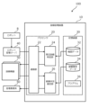
- FIG. 12 is a block diagram showing the configuration of a facility management system according to embodiment 4.
- the facility management device 10 of the facility management system 100 further includes an operation management unit 28 in addition to the functional block configuration of the facility management system 100 shown in FIG. 4.
- the operation management unit 28 is a functional block for controlling the operation of the equipment 50 in accordance with the damage situation estimated by the damage situation estimation unit 26.
- the operation feasibility of each equipment 50 is determined based on the operation feasibility information linked to the damage estimation data 34.
- Figure 13 is a diagram showing an example of damage estimation data.
- the operation feasibility information is associated with each of the peripheral equipment e(k) of the equipment failure pattern.
- Pattern (B) in the figure shows a pattern in which damage has spread to two sides of the accident location.
- Pattern (B) can be presumed to be a damage situation in which, for example, robot 8 has collided with and then fallen over. In this case, it can be determined that the possibility of damage spreading is low on the side opposite the side of the fall, so non-maintenance-requiring equipment located on the side opposite the side of the fall is set as operable equipment.
- the operation management unit 28 determines from the damage estimation data 34 the equipment failure pattern that is most similar to the equipment failure pattern formed by each peripheral equipment e(k), and generates an operation command to instruct each peripheral equipment e(k) to operate or stop based on the operation feasibility information associated with the determined equipment failure pattern.
- the generated operation command is sent from the communication unit 22 to each peripheral equipment e(k).
Landscapes
- Physics & Mathematics (AREA)
- General Physics & Mathematics (AREA)
- Engineering & Computer Science (AREA)
- Automation & Control Theory (AREA)
- Control Of Position, Course, Altitude, Or Attitude Of Moving Bodies (AREA)
- Management, Administration, Business Operations System, And Electronic Commerce (AREA)
Abstract
L'invention concerne une technologie utile à un gestionnaire lors de la gestion de l'état d'endommagement autour d'un accident impliquant un corps mobile autonome. Un système de gestion d'installation comprend : un dispositif de commande de corps mobile pour commander un corps mobile autonome ; une pluralité d'installations agencées dans une zone ; et un dispositif de gestion d'installation pour estimer l'état d'endommagement d'un accident impliquant le corps mobile autonome dans la zone. Le dispositif de commande de corps mobile transmet une position de survenue d'accident au dispositif de gestion d'installation lorsqu'un accident impliquant le corps mobile autonome survient. Le dispositif de gestion d'installation acquiert la position de survenue de l'accident à partir du dispositif de commande de corps mobile, spécifie une installation proche située à proximité de la position de survenue de l'accident parmi la pluralité d'installations, et transmet une instruction de test à l'installation proche. L'installation proche reçoit la commande de test provenant du dispositif de gestion d'installation et transmet un résultat de test obtenu par exécution du test conformément à la commande de test au dispositif de gestion d'installation. Le dispositif de gestion d'installation acquiert le résultat de test à partir de l'installation proche et estime l'état d'endommagement autour de la position de survenue de l'accident sur la base du résultat de test.
Priority Applications (3)
| Application Number | Priority Date | Filing Date | Title |
|---|---|---|---|
| CN202380101426.3A CN121729649A (zh) | 2023-08-21 | 2023-08-21 | 设备管理系统、设备管理装置、设备管理方法以及设备管理程序 |
| JP2025541183A JPWO2025041226A1 (fr) | 2023-08-21 | 2023-08-21 | |
| PCT/JP2023/030003 WO2025041226A1 (fr) | 2023-08-21 | 2023-08-21 | Système de gestion d'installation, dispositif de gestion d'installation, procédé de gestion d'installation et programme de gestion d'installation |
Applications Claiming Priority (1)
| Application Number | Priority Date | Filing Date | Title |
|---|---|---|---|
| PCT/JP2023/030003 WO2025041226A1 (fr) | 2023-08-21 | 2023-08-21 | Système de gestion d'installation, dispositif de gestion d'installation, procédé de gestion d'installation et programme de gestion d'installation |
Publications (1)
| Publication Number | Publication Date |
|---|---|
| WO2025041226A1 true WO2025041226A1 (fr) | 2025-02-27 |
Family
ID=94731678
Family Applications (1)
| Application Number | Title | Priority Date | Filing Date |
|---|---|---|---|
| PCT/JP2023/030003 Pending WO2025041226A1 (fr) | 2023-08-21 | 2023-08-21 | Système de gestion d'installation, dispositif de gestion d'installation, procédé de gestion d'installation et programme de gestion d'installation |
Country Status (3)
| Country | Link |
|---|---|
| JP (1) | JPWO2025041226A1 (fr) |
| CN (1) | CN121729649A (fr) |
| WO (1) | WO2025041226A1 (fr) |
Citations (2)
| Publication number | Priority date | Publication date | Assignee | Title |
|---|---|---|---|---|
| JP2017041166A (ja) * | 2015-08-21 | 2017-02-23 | シャープ株式会社 | 自律走行装置 |
| US20190072968A1 (en) * | 2017-09-01 | 2019-03-07 | International Business Machines Corporation | Generating driving behavior models |
-
2023
- 2023-08-21 CN CN202380101426.3A patent/CN121729649A/zh active Pending
- 2023-08-21 WO PCT/JP2023/030003 patent/WO2025041226A1/fr active Pending
- 2023-08-21 JP JP2025541183A patent/JPWO2025041226A1/ja active Pending
Patent Citations (2)
| Publication number | Priority date | Publication date | Assignee | Title |
|---|---|---|---|---|
| JP2017041166A (ja) * | 2015-08-21 | 2017-02-23 | シャープ株式会社 | 自律走行装置 |
| US20190072968A1 (en) * | 2017-09-01 | 2019-03-07 | International Business Machines Corporation | Generating driving behavior models |
Also Published As
| Publication number | Publication date |
|---|---|
| JPWO2025041226A1 (fr) | 2025-02-27 |
| CN121729649A (zh) | 2026-03-24 |
Similar Documents
| Publication | Publication Date | Title |
|---|---|---|
| EP3101818B1 (fr) | Procédé et dispositif de service d'accès sans fil | |
| EP2980546B1 (fr) | Dispositif de surveillance de bruit intelligent et procédé de surveillance de bruit l'utilisant | |
| KR101890283B1 (ko) | 실내외 측위장치 및 그것을 포함하는 측위시스템 | |
| KR102071465B1 (ko) | 광산 갱내 차량의 근접 감지 시스템 및 방법 | |
| JP7358539B2 (ja) | 未知の複雑な環境中のエリアカバレッジを評価及び最適化しながらメッシュ接続性を維持するための群れ制御アルゴリズム | |
| CN115857437A (zh) | 用于评估自动化环境的系统和安全性引导机器人 | |
| US10972868B2 (en) | Adaptive inter-ranging network | |
| US11835949B2 (en) | Autonomous device safety system | |
| CN205050361U (zh) | 一种电子边界装置及电子边界系统 | |
| Ueki et al. | Development of vehicular-collision avoidance support system by inter-vehicle communications-VCASS | |
| WO2025041226A1 (fr) | Système de gestion d'installation, dispositif de gestion d'installation, procédé de gestion d'installation et programme de gestion d'installation | |
| Li et al. | Optimal deployment of drone base stations for cellular communication by network-based localization | |
| CN115854790B (zh) | 一种多站台无人机反制系统 | |
| JPWO2019171491A1 (ja) | 移動体制御装置、移動体、移動体制御システム、移動体制御方法および移動体制御プログラム | |
| KR20210055428A (ko) | 대피 경로 안내 장치 및 방법 | |
| CN113821056B (zh) | 一种航海无人机安全测控方法、装置、设备及存储介质 | |
| Lee et al. | Seamless routing and cooperative localization of multiple mobile robots for search and rescue application | |
| JP2024516209A (ja) | 送電および/または配電ネットワークのための監視システム | |
| JP7097769B2 (ja) | 無線通信システム | |
| CN112327820A (zh) | 自动导引车agv的控制方法、装置、系统及存储介质 | |
| CN114415696B (zh) | 一种交管危险区域的控制方法 | |
| WO2026090980A1 (fr) | Procédé de supervision de plateforme mobile, et infrastructure, système de supervision et support d'informations | |
| KR102961908B1 (ko) | 비콘 기반 실내 작업자 긴급 구조 시스템 및 방법 | |
| US20250374165A1 (en) | Unmanned wireless relay mobile unit and wireless base station | |
| KR102677452B1 (ko) | 관제 센서 최적 위치 산출 장치 및 이를 이용한 관제 센서 최적 위치 산출 방법 |
Legal Events
| Date | Code | Title | Description |
|---|---|---|---|
| 121 | Ep: the epo has been informed by wipo that ep was designated in this application |
Ref document number: 23949687 Country of ref document: EP Kind code of ref document: A1 |
|
| ENP | Entry into the national phase |
Ref document number: 2025541183 Country of ref document: JP Kind code of ref document: A |
|
| WWE | Wipo information: entry into national phase |
Ref document number: 2025541183 Country of ref document: JP |
|
| NENP | Non-entry into the national phase |
Ref country code: DE |