WO2025041226A1 - Facility management system, facility management device, facility management method, and facility management program - Google Patents
Facility management system, facility management device, facility management method, and facility management program Download PDFInfo
- Publication number
- WO2025041226A1 WO2025041226A1 PCT/JP2023/030003 JP2023030003W WO2025041226A1 WO 2025041226 A1 WO2025041226 A1 WO 2025041226A1 JP 2023030003 W JP2023030003 W JP 2023030003W WO 2025041226 A1 WO2025041226 A1 WO 2025041226A1
- Authority
- WO
- WIPO (PCT)
- Prior art keywords
- accident
- equipment
- facility management
- damage situation
- test
- Prior art date
- Legal status (The legal status is an assumption and is not a legal conclusion. Google has not performed a legal analysis and makes no representation as to the accuracy of the status listed.)
- Pending
Links
Images


Classifications
-
- G—PHYSICS
- G05—CONTROLLING; REGULATING
- G05B—CONTROL OR REGULATING SYSTEMS IN GENERAL; FUNCTIONAL ELEMENTS OF SUCH SYSTEMS; MONITORING OR TESTING ARRANGEMENTS FOR SUCH SYSTEMS OR ELEMENTS
- G05B23/00—Testing or monitoring of control systems or parts thereof
- G05B23/02—Electric testing or monitoring
Definitions
- This disclosure relates to a facility management system, a facility management device, a facility management method, and a facility management program.
- Patent Document 1 discloses a technology that provides map data used by a robot to move autonomously in places where radio waves from satellites cannot be received.
- a transmitter transmits transmitter identification information that identifies the transmitter itself.
- the robot transmits the detected transmitter identification information to a map management device, and receives map data corresponding to the transmitter identification information from the map management device.
- the robot controls the drive of the drive unit that moves the robot based on an autonomous action plan created using the received map data.
- the map management device reads out the map data corresponding to the transmitter identification information notified by the robot from a memory unit and transmits it.
- Patent Document 1 allows the robot to determine its own position, but does not allow it to grasp the extent of damage in the surrounding area.
- This disclosure has been made to solve the problems described above, and aims to provide technology that is useful for administrators to manage the surrounding damage situation caused by accidents involving autonomous mobile objects.
- the facility management system disclosed herein is an facility management system including a mobile control device that controls an autonomous mobile body, a plurality of facilities arranged within an area, and a facility management device that communicates with the mobile control device and the plurality of facilities and estimates the damage status of an accident that occurs to an autonomous mobile body within the area, the mobile control device is configured to transmit the location of the accident to the facility management device when an accident occurs to the autonomous mobile body, the facility management device has a surrounding facility identification unit that acquires the location of the accident from the mobile control device, identifies surrounding facilities among the plurality of facilities that are located around the location of the accident, and transmits a test command to the surrounding facilities, and a damage status estimation unit that acquires test results from the surrounding facilities and estimates the damage status around the location of the accident based on the test results, and the surrounding facilities are configured to receive test commands from the facility management device, execute tests according to the test commands, and transmit the test results to the facility management device as test results.
- the facility management device disclosed herein is an facility management device that communicates with a mobile control device that controls an autonomous mobile body and multiple facilities located within an area, and estimates the damage situation of an accident that occurs to an autonomous mobile body within the area, and includes a peripheral facility identification unit that acquires the accident location transmitted from the mobile control device when an accident occurs to the autonomous mobile body, identifies peripheral facilities among the multiple facilities that are located around the accident location, and transmits test commands to the peripheral facilities, and a damage situation estimation unit that acquires test results from each of the peripheral facilities that perform tests in accordance with the test commands, and estimates the damage situation around the accident location based on the test results.
- the facility management method disclosed herein is a facility management method that causes a computer to estimate the damage situation of an accident involving an autonomous moving body that occurs in an area where multiple facilities are located, and includes the steps of acquiring the location of the accident when an accident occurs to an autonomous moving body, identifying peripheral facilities among the multiple facilities that are located around the location of the accident, running tests on the peripheral facilities, and estimating the damage situation around the location of the accident based on the test results.
- the facility management program disclosed herein is a facility management program that causes a computer to estimate the damage situation in the event of an accident involving an autonomous moving body that occurs in an area where multiple pieces of equipment are located, and is configured to cause the computer to acquire the location of the accident when an accident occurs to an autonomous moving body, identify peripheral equipment among the multiple pieces of equipment that is located in the vicinity of the location of the accident, run tests on the peripheral equipment, and estimate the damage situation in the vicinity of the location of the accident based on the test results.
- the facility management program disclosed herein is a facility management program that communicates with a mobile control device that controls an autonomous mobile body and multiple pieces of equipment located within an area, and causes a computer to execute the following operations: acquire the location of the accident transmitted from the mobile control device when an accident occurs to an autonomous mobile body; identify peripheral equipment among the multiple pieces of equipment that is located around the location of the accident; transmit test commands to the peripheral equipment; acquire test results from each piece of peripheral equipment that performs tests in accordance with the test commands; and estimate the damage situation around the location of the accident based on the test results.
- This disclosure makes it possible to provide technology that is advantageous for administrators to manage the surrounding damage situation caused by accidents involving autonomous moving objects.
- FIG. 1 is a diagram for explaining an overview of a facility management system according to a first embodiment
- 10 is a pattern diagram showing an example of peripheral equipment identified by the peripheral equipment identification process
- FIG. FIG. 11 is a diagram showing an example of damage estimation data.
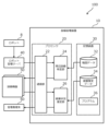
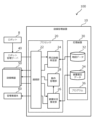
- 1 is a block diagram showing a configuration of a facility management system according to a first embodiment
- 4 is a flowchart of a process executed in the facility management system according to the first embodiment.
- FIG. 13 is a diagram illustrating a modification of the hardware resources of the equipment management device.
- FIG. 13 is a diagram showing an example of damage estimation data according to a modified example.
- FIG. 11 is a diagram showing a specific example of a damage situation estimated in the damage situation estimation process.
- FIG. 13 is a flowchart of a process executed in a facility management system according to a second embodiment. 13 is a flowchart of a process executed in a facility management system according to a third embodiment. 11 is a diagram for explaining an additional search area specification process. FIG. FIG. 13 is a block diagram showing the configuration of a facility management system according to a fourth embodiment. FIG. 11 is a diagram showing an example of damage estimation data.
- FIG. 1 is a diagram for explaining an overview of the facility management system according to the first embodiment.
- the facility management system 100 of this embodiment is a system that, when an accident occurs in an autonomous mobile object traveling within an area such as a facility, determines the damage status of facility equipment around the accident site and notifies the manager.
- Examples of the "accident” here include contact or collision of the autonomous mobile object with an obstacle, a fall of the autonomous mobile object, and disasters such as fires caused by these.
- Examples of the "facility equipment” include elevators and other lifts installed within the area, automatic doors, monitors such as information boards or advertising displays, circulators, environmental sensors, air conditioners, lighting, traffic lights, street lights, other installed robots, and the like.
- the facility management system 100 of the first embodiment is applied to a managed area of a facility or the like.
- the facility is, for example, an indoor facility, an outdoor facility, or a combination of these.
- the facility is, for example, made up of one or more buildings.
- the facility may be, for example, part of a building.
- the facility management system 100 includes a facility management device 10, a robot 8, a robot management server 40, one or more facility devices 50, and an administrator terminal 60.
- the robot 8 is an autonomous mobile object capable of autonomously traveling within an area while determining its own position. There is no limitation on the method by which the robot 8 determines its own position.
- the robot 8 detects its own position and orientation using a position sensor.
- the position sensor includes, for example, a GPS (Global Positioning System) sensor.
- the GPS sensor receives signals transmitted from multiple GPS satellites and calculates the position and orientation of the robot 8 based on the received signals.
- the position sensor may perform a well-known self-position estimation process (localization) to improve the accuracy of the current position of the robot 8.
- the robot 8 may be configured to detect its own position within the facility using a positioning device using short-range wireless communication such as UWB (Ultra Wide Band).
- UWB Ultra Wide Band
- the positioning device includes a UWB terminal that transmits UWB signals and a receive-only tag that receives UWB signals.
- Multiple UWB terminals of the positioning device are installed at intervals within the facility.
- the receive-only tag is installed on the robot 8.
- short-range wireless communication can be performed using a beacon device that uses Bluetooth (registered trademark) or the like, or a device that uses RFID, in addition to UWB.
- the robot 8 operates under the control of a robot management server 40, which serves as a mobile object control device. There are no limitations on the type, use, or operation control of the robot 8.
- the robot 8 communicates with the robot management server 40 via a communication network 6, such as wireless.
- the robot management server 40 is installed, for example, within a facility.
- the robot management server 40 communicates with the facility management device 10 via a communication network 6, such as the Internet.
- the equipment management device 10 is a device that estimates the damage status of one or more pieces of equipment 50 around the site of an accident when an accident or other malfunction occurs to a robot 8 within the area.
- the equipment management device 10 communicates with one or more pieces of equipment 50 via a communication network 6 such as the Internet.
- the equipment management device 10 also communicates with an administrator terminal 60 via the communication network 6.
- the administrator terminal 60 is a terminal managed by an administrator, and is a portable terminal device equipped with wireless communication functions, such as a smartphone.
- the administrator terminal 60 is connected to a communication network 6, such as the Internet.
- the administrator terminal 60 is equipped with an output device 62 that outputs information to the administrator.
- Examples of the output device 62 include a display device and a speaker.
- the display device may be configured as a touch panel display.
- the robot 8 in which the accident occurred transmits a fault occurrence notification, including information about the occurrence of the accident, and robot position information, including information about the location where the accident occurred, to the robot management server 40.
- the robot management server 40 transmits the received fault occurrence notification and robot position information to the equipment management device 10.
- the equipment management device 10 which has received a notification of a fault occurrence, identifies one or more pieces of equipment 50 that are located near the location where the accident occurred. This process is hereinafter referred to as the "surrounding equipment identification process.”
- the "surrounding area” here refers to a predetermined range that is likely to be affected by damage caused by an accident involving the robot 8.
- the equipment management system 100 holds map data in which the location information of one or more pieces of equipment 50 is associated with map information within the area. In the surrounding equipment identification process, the equipment management device 10 identifies and lists the surrounding equipment by referring to the map data.
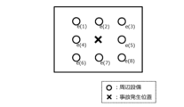
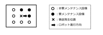
- FIG. 2 is a pattern diagram showing an example of peripheral equipment identified by the peripheral equipment identification process.
- the arrangement pattern here is a pattern that specifies the relative positions of multiple peripheral equipment with respect to the accident location. There are no limitations on the arrangement pattern.
- FIG. 2 shows an example of an arrangement pattern in which peripheral equipment is aligned at eight points in front of, behind, to the left, to the right, in front of, in front of, in front of, in front of, in front of, in rear of, and in rear of the accident location.
- the arrangement pattern may be, for example, a pattern in which the equipment is aligned on a circumference surrounding the accident location. There are no limitations on the method for approximating the positions of the equipment 50 to the arrangement of the specified arrangement pattern.
- the equipment management device 10 sends a test command to each identified peripheral equipment e(k). This process is hereinafter referred to as the "test process".
- the test command includes a communication test command to instruct a test of the communication state, and an operation test command to instruct a test of the operation state.
- the equipment management device 10 first sends a communication test command to each identified peripheral equipment e(k). Then, the equipment management device 10 receives the communication test results sent from each peripheral equipment e(k). If the received communication test results are normal, the equipment management device 10 sends an operation test command to each identified peripheral equipment e(k). Then, the equipment management device 10 receives the operation test results sent from each peripheral equipment e(k).
- the equipment management device 10 estimates the damage situation around the location where the failure occurred based on the received test results. This process is hereinafter referred to as the "damage situation estimation process".
- damage estimation data is referenced.
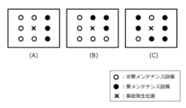
- FIG. 3 is a diagram showing an example of damage estimation data.
- FIG. 3 illustrates the layout of each peripheral equipment e(k) existing around the accident occurrence location, and multiple types of equipment failure patterns associated with attributes of whether each peripheral equipment e(k) is maintenance-required equipment that requires maintenance or non-maintenance-required equipment that does not require maintenance.
- (A) in the figure shows a pattern in which damage is concentrated on one side of the accident occurrence location.
- Pattern (A) can be estimated as a damage situation in which, for example, the robot 8 stops after a collision without falling over.
- (B) in the figure shows a pattern in which damage extends to two sides of the accident occurrence location.
- Pattern (B) can be estimated as a damage situation in which, for example, the robot 8 falls over after a collision.
- (C) in the figure shows a pattern in which damage extends to all sides of the accident occurrence location.
- Pattern (C) can be estimated to be a damage situation in which, for example, an accident involving robot 8 has caused a fire to break out in the surrounding area.
- the damage estimation data corresponds to information on the estimated damage situation for each equipment failure pattern.
- the equipment management device 10 generates damage situation information that estimates the damage situation by comparing the test results of the surrounding equipment with the damage estimation data.
- the "damage situation information" generated here includes whether or not maintenance is required for each piece of surrounding equipment, the state of the robot 8, and the accident situation.
- the accident situation includes whether or not the robot 8 has fallen, the extent of the damage, etc.
- the damage situation information is transmitted to the administrator terminal 60 via the communication network 6.
- the administrator terminal 60 outputs the received damage status information from the output device 62 to notify the administrator.
- notification means by the output device 62 include display output on a screen, audio output from a speaker, etc.
- the facility management system 100 includes the above-mentioned facility management device 10, a robot 8, a robot management server 40, one or more facility devices 50, and an administrator terminal 60.
- the facility management device 10 is a microcomputer that includes at least one processor 20 and at least one storage device 30.
- the facility management device 10 is also called an information processing device.
- the storage device 30 stores map data 32, damage estimation data 34, and an equipment management program 36.
- the map data 32 includes map information within the area, map information inside the building, and position coordinate information for each piece of equipment 50.
- the damage estimation data 34 stores the multiple types of equipment failure patterns described above.
- the map data 32 and damage estimation data 34 may be stored in a server capable of communicating with the equipment management device 10, such as the robot management server 40 or a cloud server.
- the processor 20 includes a CPU (Central Processing Unit).
- the processor 20 reads and executes the equipment management program 36 to realize various functions of the equipment management device 10.
- the equipment management program 36 may be recorded on a computer-readable recording medium.
- the equipment management device 10 has the following functional blocks: a communication unit 22, a surrounding equipment identification unit 24, and a damage situation estimation unit 26.
- the communication unit 22 is a functional block for communicating with external devices.
- the communication unit 22 communicates with the robot management server 40, the equipment 50, and the manager terminal 60 via the communication network 6.
- the peripheral equipment identification unit 24 is a functional block for performing peripheral equipment identification processing.
- the damage situation estimation unit 26 is a functional block for performing damage situation estimation processing. Below, the specific processing executed in the equipment management device 10 will be explained with reference to a flowchart.
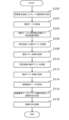
- Fig. 5 is a flowchart of processing executed in the facility management system according to the first embodiment.
- the routine shown in Fig. 5 is executed by the processor 20 of the facility management device 10 executing the facility management program 36 stored in the storage device 30.
- This routine also represents a part of a facility management method for estimating the damage situation caused by an accident involving the robot 8 in the facility management system 100.
- step S100 of the routine shown in FIG. 5 the communication unit 22 receives a fault occurrence notification and robot position information from the robot management server 40.
- the received fault occurrence notification and robot position information are sent to the peripheral equipment identification unit 24.
- step S102 the process proceeds to step S102.
- step S102 the surrounding facility identification unit 24 acquires map data stored in the storage device 30. After the processing of step S102 is performed, the process proceeds to step S104.
- step S104 the surrounding equipment identification unit 24 executes a surrounding equipment identification process to identify surrounding equipment from the map data and the robot position information.
- the surrounding equipment identification unit 24 refers to the map data to identify each piece of surrounding equipment e(k) located in each section R(k) surrounding the accident location included in the robot position information from among the equipment 50.
- step S106 the peripheral equipment identification unit 24 executes a test process to perform a communication test with each identified peripheral equipment e(k). Specifically, the peripheral equipment identification unit 24 transmits a communication test command from the communication unit 22 to each peripheral equipment e(k) to determine whether the communication state is good. After the process of step S106 is performed, the process proceeds to step S108.
- step S108 the communication unit 22 receives the communication test results, including the results of the communication tests carried out in each peripheral equipment e(k), from each peripheral equipment e(k) and sends them to the damage situation estimation unit 26. After the processing of step S108 is performed, the process proceeds to step S110.
- step S110 the peripheral equipment identification unit 24 executes a test process to perform an operation test with each identified peripheral equipment e(k). Specifically, the peripheral equipment identification unit 24 transmits an operation test command from the communication unit 22 to each peripheral equipment e(k) to determine whether the operation of each peripheral equipment e(k) is normal. After the process of step S110 is performed, the process proceeds to step S112.
- step S112 the communication unit 22 receives operational test results, including the results of the operational tests carried out in each peripheral facility e(k), from each peripheral facility e(k) and sends them to the damage situation estimation unit 26. After the processing in step S112 is performed, the process proceeds to step S114.
- step S114 the damage situation estimation unit 26 acquires the damage estimation data stored in the storage device 30. After the processing of step S114 is performed, the process proceeds to step S116.
- step S116 the damage situation estimation unit 26 performs a damage situation estimation process. Specifically, the damage situation estimation unit 26 compares the communication test results acquired in step S108 and the operation test results acquired in step S110 with the damage estimation data acquired in step S114.
- peripheral equipment e(k) identified in step S104 peripheral equipment with good communication test results and good operation test results is associated as equipment not requiring maintenance, and peripheral equipment with at least one of the communication test results and the operation test results being poor is associated as equipment requiring maintenance.
- the damage situation estimation unit 26 compares the equipment failure pattern formed by each peripheral equipment e(k) with the equipment failure pattern in the damage estimation data, and determines the damage situation of the most similar equipment failure pattern as the estimated damage situation. Then, the damage situation estimation unit 26 generates damage situation information including the estimated damage situation and whether or not each peripheral equipment e(k) requires maintenance.
- step S118 the damage situation estimation unit 26 transmits the damage situation information from the communication unit 22 to the administrator terminal 60.
- the administrator terminal 60 notifies the administrator of the received damage situation information.
- the facility management system 100 of the first embodiment may adopt the following modified aspects. Note that these modified aspects may also be applied to facility management systems of other embodiments described later.
- Robot management server 40 Some or all of the functions of the robot management server 40 may be realized as functions of the processor 20 of the facility management device 10. Some or all of the functions of the robot management server 40 may be mounted on a device provided outside the facility. Some or all of the functions of the robot management server 40 may be implemented across multiple pieces of hardware. In this case, each piece of hardware is connected to each other so that they can communicate with each other through a communication network 6 such as the Internet. Some or all of the functions of the robot management server 40 may be implemented by processing and storage resources on a cloud service.
- FIG. 6 is a diagram showing a modified example of the hardware resources of the equipment management device 10.
- the equipment management device 10 includes, for example, a processor 20, a storage device 30, and a processing circuit 72 including dedicated hardware 70.
- FIG. 6 shows an example in which some of the functions of the equipment management device 10 are realized by the dedicated hardware 70. All of the functions of the equipment management device 10 may be realized by the dedicated hardware 70.
- the dedicated hardware 70 a single circuit, a composite circuit, a programmed processor, a parallel programmed processor, an ASIC, an FPGA, or a combination of these can be adopted.
- the role of the storage device 30 may be played by a cloud or the like independent of the facility management device 10.
- the role of the communication unit 22 may be played by a data platform or the like independent of the facility management device 10.
- the damage situation estimation unit 26 may be configured to estimate the damage situation more accurately using information on the traveling direction of the robot 8.
- the robot 8 detects its traveling direction from the orientation detected by the position sensor.
- the robot 8 detects its traveling direction from the movement trajectory of its own position detected by the position sensor.
- the robot 8 transmits a fault occurrence notification and robot position information including information on the accident location and the traveling direction of the robot 8 to the robot management server 40.
- the robot management server 40 transmits the received fault occurrence notification and robot position information to the equipment management device 10.
- the damage situation estimation unit 26 associates each peripheral equipment e(k) with an attribute of whether it is maintenance-requiring equipment or maintenance-requiring equipment, and associates the attribute of the traveling direction of the robot 8 with the accident occurrence position.
- FIG. 7 is a diagram showing an example of damage estimation data of the modified example.
- FIG. 7 illustrates an example of an equipment failure pattern in which the attribute of whether each peripheral equipment e(k) existing around the accident occurrence position is maintenance-requiring equipment that requires maintenance or maintenance-free equipment that does not require maintenance is associated with the attribute of the traveling direction of the robot at the accident occurrence position.
- the equipment failure pattern of FIG. 7 shows a pattern in which damage occurs on two sides of the accident occurrence position, including the traveling direction.
- Such a pattern can be estimated as a damage situation in which, for example, the robot 8 collides and then falls to the left of the traveling direction.
- the storage device 30 stores damage estimation data 34 including multiple equipment failure patterns associated with the attribute of the traveling direction as shown in FIG. 7.
- the equipment management device 10 generates damage situation information that estimates the damage situation by comparing the test results of the peripheral equipment with the damage estimation data 34.
- This modified damage situation estimation process makes it possible to more accurately estimate the damage situation caused by an accident involving the robot 8.
- the test process may be either a communication test or an operation test.
- the peripheral equipment specifying unit 24 transmits either a communication test command or an operation test command to each peripheral equipment e(k).
- Damage Estimation Data 34 It is considered that the extent of damage caused by an accident may differ depending on the specifications of the robot 8. Therefore, the damage estimation data 34 may be set individually according to the specifications of the robot 8.
- Embodiment 2 In the second embodiment, differences from the example disclosed in the first embodiment will be described in particular detail. For features not described in the second embodiment, any of the features of the example disclosed in the first embodiment may be adopted.
- the facility management system 100 of the second embodiment is characterized by the process of identifying surrounding facilities in units of pre-defined zone areas and judging the damage status.
- Map data 32 includes map information within the area, map information for the interior of the building, and position coordinate information for each piece of equipment 50.
- the map information includes division information that divides the area into multiple division areas. There are no limitations on the shape, size, or division method of each division area. For example, the map information includes division information that divides the area into a grid pattern.
- the equipment management device 10 refers to the map data to identify the area of the equipment 50 that includes the location where the accident occurred as the accident occurrence area, and identifies the equipment 50 within the identified accident occurrence area as the surrounding equipment e(k).
- the equipment management device 10 calculates the proportion of defective equipment that was found to be defective in the test process results among the surrounding equipment e(k) within the accident occurrence area. The equipment management device 10 then estimates the damage situation according to the calculated proportion. Typically, when the proportion of defective equipment is large, the equipment management device 10 determines that the scale of damage is greater than when the proportion is small.
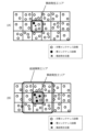
- FIG. 8 shows a specific example of the damage situation estimated in the damage situation estimation process.
- map information including partition information in which the area is divided into a grid shows several examples of patterns in which each piece of surrounding equipment e(k) in the accident area is associated with an attribute indicating whether it is maintenance-requiring equipment that requires maintenance or non-maintenance-requiring equipment that does not require maintenance.
- (A) in the figure shows a pattern in which the proportion of defective equipment determined to be maintenance-requiring equipment among the surrounding equipment e(k) in the accident area is small. Since the damage to the surrounding equipment e(k) in the accident area is relatively small in pattern (A), it can be estimated that the damage situation is one in which a small-scale accident has occurred.
- Pattern (B) in the figure shows a pattern in which the proportion of defective equipment determined to require maintenance is high among the surrounding equipment e(k) within the accident area.
- Pattern (A) can be estimated as a damage situation in which a large-scale accident has occurred, since the damage to the surrounding equipment e(k) within the accident area is relatively large.
- the processing of the facility management system 100 according to the second embodiment makes it possible to identify areas where damage may occur due to an accident, and then estimate the scale of damage within the identified areas.
- Fig. 9 is a flowchart of processing executed in the facility management system according to the second embodiment.
- the routine shown in Fig. 9 is executed by the processor 20 of the facility management device 10 executing the facility management program 36 stored in the storage device 30.
- This routine also represents a part of a facility management method for estimating the damage situation caused by an accident involving the robot 8 in the facility management system 100.
- steps S200 and S202 of the routine shown in FIG. 9 the same processing as in steps S100 and S102 of the routine shown in FIG. 5 is executed. After the processing in step S202 is executed, the processing proceeds to step S204.
- step S204 the surrounding equipment identification unit 24 executes a surrounding equipment identification process to identify surrounding equipment from the map data and the robot position information.
- the surrounding equipment identification unit 24 first identifies the partitioned area that includes the accident location included in the robot position information as the accident occurrence area, and identifies the equipment 50 in the identified accident occurrence area as surrounding equipment e(k).
- the process proceeds to step S206.
- steps S206, S208, S210, and S212 test processing similar to steps S106, S106, S106, and S106 of the routine shown in FIG. 5 is executed. After the processing in step S212 is executed, the process proceeds to step S214.
- step S214 the damage situation estimation unit 26 performs a damage situation estimation process. Specifically, for each peripheral equipment e(k) identified in step S204, the damage situation estimation unit 26 associates peripheral equipment for which both the communication test results and the operation test results are good as equipment not requiring maintenance, and associates peripheral equipment for which at least one of the communication test results and the operation test results is poor as equipment requiring maintenance. Next, the damage situation estimation unit 26 calculates the proportion of peripheral equipment e(k) that does not require maintenance. After the process of step S214 has been performed, the process proceeds to step S216.
- step S216 the damage situation estimation unit 26 determines the damage situation such that the larger the ratio calculated in the processing of step S214, the greater the scale of damage. Then, the damage situation estimation unit 26 generates damage situation information including the estimated damage situation and whether or not maintenance is required for each peripheral facility e(k).
- step S218 the damage situation estimation unit 26 transmits the damage situation information from the communication unit 22 to the administrator terminal 60.
- the administrator terminal 60 notifies the administrator of the received damage situation information.
- Embodiment 3 In the third embodiment, differences from the example disclosed in the second embodiment will be described in particular detail. For features not described in the third embodiment, any of the features of the example disclosed in the second embodiment may be adopted.
- Specific Processing Executed in the Facility Management System of the Third Embodiment Fig. 10 is a flowchart of processing executed in the facility management system of the third embodiment.
- the routine shown in Fig. 10 is executed by the processor 20 of the facility management device 10 executing the facility management program 36 stored in the storage device 30 after the routine for estimating the damage situation for the accident area shown in Fig. 9 has been executed.
- This routine also represents a part of the facility management method for estimating the damage situation caused by an accident involving the robot 8 in the facility management system 100.
- step S300 of the routine shown in FIG. 10 the surrounding equipment identification unit 24 judges whether the proportion of defective equipment calculated in the processing of step S219 is equal to or greater than the judgment criterion.
- the proportion of defective equipment is related to the scale of damage caused by an accident.
- the judgment criterion here is a preset value that represents the proportion of the damage caused by an accident that may extend to the periphery of the accident area.
- the judgment criterion is, for example, 50%.
- step S302 the surrounding equipment identification unit 24 identifies an additional search area adjacent to the accident occurrence area.
- This process is hereinafter referred to as the "additional search area identification process.”
- Figure 11 is a diagram for explaining the additional search area identification process.
- (A) in Figure 11 illustrates an example in which the proportion of defective equipment in the accident occurrence area is less than the judgment criterion. In this case, it is determined that there is a low possibility of damage to the area surrounding the accident occurrence area, and the additional area identification process is not performed.
- (B) in Figure 11 illustrates an example in which the proportion of defective equipment in the accident occurrence area is equal to or greater than the judgment criterion.
- the surrounding equipment identification unit 24 identifies multiple partitioned areas surrounding the periphery of the accident occurrence area as additional search areas.
- step S302 the surrounding equipment identification unit 24 identifies the equipment devices 50 located within each of the partitioned areas that make up the additional search area as surrounding equipment e(k).
- step S304 the process proceeds to step S304.
- steps S304, S306, S308, and S310 the same test processing as in steps S206, S208, S210, and S212 shown in FIG. 9 is executed. After the processing in step S310 is executed, the processing proceeds to step S312.
- step S312 the damage situation estimation unit 26 performs a damage situation estimation process. Specifically, for each peripheral equipment e(k) in the additional search area identified in step S302, the damage situation estimation unit 26 associates peripheral equipment for which both the communication test results and the operation test results are good as equipment not requiring maintenance, and associates peripheral equipment for which at least one of the communication test results and the operation test results is poor as equipment requiring maintenance. Next, the damage situation estimation unit 26 calculates the proportion of peripheral equipment e(k) that does not require maintenance in each partition area of the additional search area. After the process of step S312 is performed, the process proceeds to step S314.
- step S316 the damage situation estimation unit 26 transmits the damage situation information from the communication unit 22 to the administrator terminal 60.
- the administrator terminal 60 notifies the administrator of the received damage situation information.
- the facility management device 10 According to the processing of the facility management device 10 according to the third embodiment, it is determined whether or not it is necessary to execute a damage situation estimation process in an additional search area, depending on the damage situation in the accident area caused by the accident involving the robot 8. This makes it possible to determine the damage situation over a wider area depending on the damage situation in the accident area.
- the additional search area may include a wider range of divided areas, as long as they are divided areas where damage from the accident may occur.
- the additional search area may be all divided areas adjacent to the accident area, or a portion of those divided areas.
- the additional search area may be determined according to any rule. Examples of such arbitrary rules include a method of searching for divided areas that are adjacent to the edge of the accident area at a specified rate or more as the additional search area, or a method of calculating a directional vector along which damage will be concentrated from the position of equipment requiring maintenance within the accident area, and searching for divided areas in the direction of that directional vector as the additional search area.
- the facility management system 100 of the fourth embodiment is characterized by the process of controlling the operation of the facility devices 50 in accordance with the damage caused by an accident.
- FIG. 12 is a block diagram showing the configuration of a facility management system according to embodiment 4.
- the facility management device 10 of the facility management system 100 further includes an operation management unit 28 in addition to the functional block configuration of the facility management system 100 shown in FIG. 4.
- the operation management unit 28 is a functional block for controlling the operation of the equipment 50 in accordance with the damage situation estimated by the damage situation estimation unit 26.
- the operation feasibility of each equipment 50 is determined based on the operation feasibility information linked to the damage estimation data 34.
- Figure 13 is a diagram showing an example of damage estimation data.
- the operation feasibility information is associated with each of the peripheral equipment e(k) of the equipment failure pattern.
- Pattern (B) in the figure shows a pattern in which damage has spread to two sides of the accident location.
- Pattern (B) can be presumed to be a damage situation in which, for example, robot 8 has collided with and then fallen over. In this case, it can be determined that the possibility of damage spreading is low on the side opposite the side of the fall, so non-maintenance-requiring equipment located on the side opposite the side of the fall is set as operable equipment.
- the operation management unit 28 determines from the damage estimation data 34 the equipment failure pattern that is most similar to the equipment failure pattern formed by each peripheral equipment e(k), and generates an operation command to instruct each peripheral equipment e(k) to operate or stop based on the operation feasibility information associated with the determined equipment failure pattern.
- the generated operation command is sent from the communication unit 22 to each peripheral equipment e(k).
Landscapes
- Physics & Mathematics (AREA)
- General Physics & Mathematics (AREA)
- Engineering & Computer Science (AREA)
- Automation & Control Theory (AREA)
- Control Of Position, Course, Altitude, Or Attitude Of Moving Bodies (AREA)
- Management, Administration, Business Operations System, And Electronic Commerce (AREA)
Abstract
Description
本開示は、設備管理システム、設備管理装置、設備管理方法、及び設備管理プログラムに関する。 This disclosure relates to a facility management system, a facility management device, a facility management method, and a facility management program.
特許文献1には、衛星からの電波が受信できない場所においてロボットが自律移動を行うために用いる地図データを提供する技術が開示されている。この技術のシステムにおいて、送信機は、自送信機を識別する送信機識別情報を送信する。ロボットは、検出された送信機識別情報を地図管理装置に送信し、地図管理装置から送信機識別情報に対応した地図データを受信する。ロボットは、受信した地図データを用いて作成した自律行動計画に基づいて、ロボットの移動させる駆動部の駆動を制御する。地図管理装置は、ロボットから通知された送信機識別情報に対応した地図データを記憶部から読み出して送信する。 Patent Document 1 discloses a technology that provides map data used by a robot to move autonomously in places where radio waves from satellites cannot be received. In the system of this technology, a transmitter transmits transmitter identification information that identifies the transmitter itself. The robot transmits the detected transmitter identification information to a map management device, and receives map data corresponding to the transmitter identification information from the map management device. The robot controls the drive of the drive unit that moves the robot based on an autonomous action plan created using the received map data. The map management device reads out the map data corresponding to the transmitter identification information notified by the robot from a memory unit and transmits it.
施設内を走行する自律移動型のロボットに障害物への接触等の事故が発生することが考えられる。事故が発生した場合において、事故現場周辺の撮像画像を得る手段がない場合、発生現場周辺の被害状況を逸早く把握することが困難となる。特許文献1の技術では、ロボットが自己位置を把握することはできるものの、周辺の被害状況を把握することは行われていない。 It is conceivable that an autonomous mobile robot traveling within a facility may have an accident, such as coming into contact with an obstacle. If an accident does occur and there is no means of obtaining captured images of the area around the accident site, it becomes difficult to quickly grasp the extent of the damage in the area around the accident site. The technology in Patent Document 1 allows the robot to determine its own position, but does not allow it to grasp the extent of damage in the surrounding area.
本開示は、上述のような課題を解決するためになされたもので、自律移動体の事故による周辺の被害状況を管理者が管理する上で有用な技術を提供することを目的とする。 This disclosure has been made to solve the problems described above, and aims to provide technology that is useful for administrators to manage the surrounding damage situation caused by accidents involving autonomous mobile objects.
本開示の設備管理システムは、自律移動体を制御する移動体制御装置と、エリア内に配置された複数の設備と、移動体制御装置及び複数の設備と通信し、エリア内で自律移動体に発生した事故の被害状況を推定する設備管理装置と、を備えた設備管理システムであって、移動体制御装置は、自律移動体の事故が発生したときに事故発生位置を設備管理装置に送信するように構成され、設備管理装置は、移動体制御装置から事故発生位置を取得し、複数の設備のうち事故発生位置の周辺に位置する周辺設備を特定し、周辺設備に対してテスト指令を送信する周辺設備特定部と、周辺設備からテスト結果を取得し、テスト結果に基づいて事故発生位置の周辺の被害状況を推定する被害状況推定部と、を有し、周辺設備は、設備管理装置からテスト指令を受信し、テスト指令に従いテストを実行し、テストの結果をテスト結果として設備管理装置に送信するように構成されるものである。 The facility management system disclosed herein is an facility management system including a mobile control device that controls an autonomous mobile body, a plurality of facilities arranged within an area, and a facility management device that communicates with the mobile control device and the plurality of facilities and estimates the damage status of an accident that occurs to an autonomous mobile body within the area, the mobile control device is configured to transmit the location of the accident to the facility management device when an accident occurs to the autonomous mobile body, the facility management device has a surrounding facility identification unit that acquires the location of the accident from the mobile control device, identifies surrounding facilities among the plurality of facilities that are located around the location of the accident, and transmits a test command to the surrounding facilities, and a damage status estimation unit that acquires test results from the surrounding facilities and estimates the damage status around the location of the accident based on the test results, and the surrounding facilities are configured to receive test commands from the facility management device, execute tests according to the test commands, and transmit the test results to the facility management device as test results.
本開示の設備管理装置は、自律移動体を制御する移動体制御装置及びエリア内に配置された複数の設備と通信し、エリア内で自律移動体に発生した事故の被害状況を推定する設備管理装置であって、自律移動体の事故が発生したときに移動体制御装置から送信される事故発生位置を取得し、複数の設備のうち事故発生位置の周辺に位置する周辺設備を特定し、周辺設備に対してテスト指令を送信する周辺設備特定部と、テスト指令に従いテストを実行したテスト結果を周辺設備のそれぞれから取得し、テスト結果に基づいて事故発生位置の周辺の被害状況を推定する被害状況推定部と、を備えるものである。 The facility management device disclosed herein is an facility management device that communicates with a mobile control device that controls an autonomous mobile body and multiple facilities located within an area, and estimates the damage situation of an accident that occurs to an autonomous mobile body within the area, and includes a peripheral facility identification unit that acquires the accident location transmitted from the mobile control device when an accident occurs to the autonomous mobile body, identifies peripheral facilities among the multiple facilities that are located around the accident location, and transmits test commands to the peripheral facilities, and a damage situation estimation unit that acquires test results from each of the peripheral facilities that perform tests in accordance with the test commands, and estimates the damage situation around the accident location based on the test results.
本開示の設備管理方法は、複数の設備が配置されたエリアで発生した自律移動体の事故の被害状況を推定することをコンピュータに実行させる設備管理方法であって、自律移動体の事故が発生したときに事故発生位置を取得するステップと、複数の設備のうち事故発生位置の周辺に位置する周辺設備を特定するステップと、周辺設備のテストを実行するステップと、テストのテスト結果に基づいて、事故発生位置の周辺の被害状況を推定するステップと、を備えるものである。 The facility management method disclosed herein is a facility management method that causes a computer to estimate the damage situation of an accident involving an autonomous moving body that occurs in an area where multiple facilities are located, and includes the steps of acquiring the location of the accident when an accident occurs to an autonomous moving body, identifying peripheral facilities among the multiple facilities that are located around the location of the accident, running tests on the peripheral facilities, and estimating the damage situation around the location of the accident based on the test results.
本開示の設備管理プログラムは、複数の設備が配置されたエリアで発生した自律移動体の事故の被害状況を推定することをコンピュータに実行させる設備管理プログラムであって、自律移動体の事故が発生したときに事故発生位置を取得し、複数の設備のうち事故発生位置の周辺に位置する周辺設備を特定し、周辺設備のテストを実行し、テストのテスト結果に基づいて、事故発生位置の周辺の被害状況を推定する、ことをコンピュータに実行させるように構成されるものである。 The facility management program disclosed herein is a facility management program that causes a computer to estimate the damage situation in the event of an accident involving an autonomous moving body that occurs in an area where multiple pieces of equipment are located, and is configured to cause the computer to acquire the location of the accident when an accident occurs to an autonomous moving body, identify peripheral equipment among the multiple pieces of equipment that is located in the vicinity of the location of the accident, run tests on the peripheral equipment, and estimate the damage situation in the vicinity of the location of the accident based on the test results.
本開示の設備管理プログラムは、自律移動体を制御する移動体制御装置及びエリア内に配置された複数の設備と通信し、エリア内で自律移動体に発生した事故の被害状況を推定することをコンピュータに実行させる設備管理プログラムであって、自律移動体の事故が発生したときに移動体制御装置から送信される事故発生位置を取得し、複数の設備のうち事故発生位置の周辺に位置する周辺設備を特定し、周辺設備に対してテスト指令を送信し、テスト指令に従いテストを実行したテスト結果を周辺設備のそれぞれから取得し、テスト結果に基づいて事故発生位置の周辺の被害状況を推定する、ことをコンピュータに実行させるように構成されるものである。 The facility management program disclosed herein is a facility management program that communicates with a mobile control device that controls an autonomous mobile body and multiple pieces of equipment located within an area, and causes a computer to execute the following operations: acquire the location of the accident transmitted from the mobile control device when an accident occurs to an autonomous mobile body; identify peripheral equipment among the multiple pieces of equipment that is located around the location of the accident; transmit test commands to the peripheral equipment; acquire test results from each piece of peripheral equipment that performs tests in accordance with the test commands; and estimate the damage situation around the location of the accident based on the test results.
本開示によれば、自律移動体の事故による周辺の被害状況を管理者が管理する上で有利な技術を提供することが可能となる。 This disclosure makes it possible to provide technology that is advantageous for administrators to manage the surrounding damage situation caused by accidents involving autonomous moving objects.
以下、図面を参照して実施の形態について説明する。なお、各図において共通する要素には、同一の符号を付して、重複する説明を省略する。 Below, the embodiments will be explained with reference to the drawings. Note that elements common to each drawing will be given the same reference numerals, and duplicate explanations will be omitted.
1.実施の形態1.
1-1.実施の形態1の設備管理システムの概要
図1は、実施の形態1に係る設備管理システムの概要を説明するための図である。本実施の形態の設備管理システム100は、施設等のエリア内を走行する自律移動体に事故が発生した場合に、事故発生現場周辺の設備機器の被害状況を判定して管理者に通知するシステムである。ここでの「事故」は、自律移動体の障害物への接触或いは衝突、自律移動体の転倒、及びこれらに起因する火災等の災害、等が例示される。「設備機器」は、エリア内に設置されたエレベーター等の昇降機、自動ドア、案内掲示板或いは広告表示等のモニター、サーキュレーター、環境センサ類、空調、照明、信号機、街灯、他の設置型ロボット、などが例示される。
1. Embodiment 1
1-1. Overview of the Facility Management System of the First Embodiment FIG. 1 is a diagram for explaining an overview of the facility management system according to the first embodiment. The
実施の形態1の設備管理システム100は、施設等の管理されたエリアに適用される。施設は、例えば、屋内施設もしくは屋外施設、またはこれらを複合した施設などである。施設は、例えば、1つまたは複数の建物などからなる。施設は、例えば、建物などの一部であってもよい。設備管理システム100は、設備管理装置10と、ロボット8と、ロボット管理サーバ40と、1又は複数の設備機器50と、管理者端末60と、を含む。
The
ロボット8は、自己位置を把握しながらエリア内を自律的に走行可能な自律移動体である。ロボット8が自己位置を把握する方法に限定はない。例えば、ロボット8は、位置センサを用いて自己の位置及び方位を検出する。位置センサは、例えばGPS(Global Positioning System)センサを含む。GPSセンサは、複数のGPS衛星から送信される信号を受信し、受信信号に基づいてロボット8の位置及び方位を算出する。位置センサは、周知の自己位置推定処理(localization)を行い、ロボット8の現在位置の精度を高めてもよい。或いは、ロボット8は、例えばUWB(Ultra Wide Band)等の近距離無線通信を用いた測位装置により施設内の自己位置を検知するように構成されていてもよい。この場合、測位装置は、UWB信号を発信するUWB端末とUWB信号を受信する受信専用タグを含む。測位装置のUWB端末は、施設内において間隔を開けて複数設置される。受信専用タグはロボット8に設置される。これにより、受信専用タグが設けられたロボット8が施設内を移動すると、当該ロボット8の位置を高精度に測位することができる。また、近距離無線通信は、UWBの他、Bluetooth(登録商標)等を利用したビーコン装置、又はRFIDを用いた装置でもよい。
The
ロボット8は、移動体制御装置としてのロボット管理サーバ40による制御に基づいて稼働する。ロボット8の種類、用途、及び稼働制御に限定はない。ロボット8は、例えば無線などの通信ネットワーク6を介してロボット管理サーバ40と通信する。ロボット管理サーバ40は、例えば施設内に設けられる。ロボット管理サーバ40は、例えばインターネットなどの通信ネットワーク6を介して設備管理装置10と通信する。
The
設備管理装置10は、エリア内においてロボット8に事故等の障害が発生した場合、事故発生現場周辺の1又は複数の設備機器50の被害状況を推定する装置である。設備管理装置10は、例えばインターネットなどの通信ネットワーク6を介して1又は複数の設備機器50と通信する。また、設備管理装置10は、通信ネットワーク6を介して管理者端末60と通信する。
The
管理者端末60は、管理者が管理する端末であり、例えばスマートフォンなどの無線通信の機能を搭載した可搬な端末装置である。管理者端末60は、例えばインターネットなどの通信ネットワーク6に接続される。この例において、管理者端末60は、管理者に情報を出力する出力装置62を備える。出力装置62としては、例えば、表示装置、スピーカ等が例示される。なお、表示装置は、タッチパネル式ディスプレイとして構成されていてもよい。
The
このような設備管理システム100が適用されるエリア内においてロボット8に事故が発生した場合を考える。事故が発生したロボット8は、事故が発生したことの情報を含む障害発生通知と、事故発生位置の情報を含むロボット位置情報を、ロボット管理サーバ40へ送信する。ロボット管理サーバ40は、受信した障害発生通知とロボット位置情報を、設備管理装置10へ送信する。
Let us consider a case where an accident occurs to a
障害発生通知を受信した設備管理装置10は、1又は複数の設備機器50のうち事故発生位置の周辺に配置されている周辺設備を特定する。この処理は、以下「周辺設備特定処理」と呼ばれる。ここでの「周辺」は、ロボット8の事故による被害が及ぶ可能性のある範囲として、予め定められた範囲である。設備管理システム100は、1又は複数の設備機器50の配置情報がエリア内の地図情報に関連付けられた地図データを保有している。周辺設備特定処理において、設備管理装置10は、地図データを参照することによって周辺設備を特定してリスト化する。
The
図2は、周辺設備特定処理によって特定される周辺設備の一例を示すパターン図である。周辺設備特定処理において、設備管理装置10は、例えば事故発生位置の周辺の設備機器50の位置を規定の配列パターンの配置に近似した上で周辺設備e(k)(k=1, … ,n)として特定する。ここでの配列パターンは、事故発生位置に対する複数の周辺設備の相対位置を規定したパターンである。配列パターンに限定はない。図2には、事故発生位置の前、後、左、右、右前、左前、右後、左後の8地点に周辺設備を整列配置する配列パターンが例示されている。配列パターンは、例えば、事故発生位置を囲む円周上に整列配置するパターンでもよい。また、設備機器50の位置を規定の配列パターンの配置に近似する方法に限定はない。
FIG. 2 is a pattern diagram showing an example of peripheral equipment identified by the peripheral equipment identification process. In the peripheral equipment identification process, the
設備管理装置10は、特定された各周辺設備e(k)に対してテスト指令を送信する。この処理は、以下「テスト処理」と呼ばれる。テスト指令は、通信状態のテストを指示するための通信テスト指令と、動作状態のテストを指示するための動作テスト指令と、を含む。テスト処理において、設備管理装置10は、先ず特定された各周辺設備e(k)に通信テスト指令を送信する。そして、設備管理装置10は、各周辺設備e(k)から送信される通信テスト結果を受信する。受信した通信テスト結果が正常であった場合、特定された各周辺設備e(k)に動作テスト指令を送信する。そして、設備管理装置10は、各周辺設備e(k)から送信される動作テスト結果を受信する。
The
設備管理装置10は、受信したテスト結果に基づいて、障害発生位置の周辺の被害状況を推定する。この処理は、以下「被害状況推定処理」と呼ばれる。被害状況推定処理では、被害推定データが参照される。図3は、被害推定データの一例を示す図である。図3には、事故発生位置の周辺に存在する各周辺設備e(k)の配置、及びこれら各周辺設備e(k)が、それぞれメンテナンスが必要な要メンテナンス設備であるか、或いはメンテナンスが不要な非要メンテナンス設備であるかの属性を関連付けた複数種類の設備故障パターンが例示されている。例えば、図中の(A)は、事故発生位置の一方面に被害が集中しているパターンを示している。パターン(A)は、例えばロボット8が衝突した後、転倒せずに停止している被害状況であると推定することができる。図中の(B)は、事故発生位置の二方面に被害が及んでいるパターンを示している。パターン(B)は、例えばロボット8が衝突した後、転倒した被害状況であると推定することができる。また、図中の(C)は、事故発生位置の全方面に被害が及んでいるパターンを示している。パターン(C)は、例えばロボット8の事故により、周囲に火災が発生した被害状況であると推定することができる。
The
被害推定データは、設備故障パターン毎に、推定される被害状況の情報が対応付けられている。被害状況推定処理において、設備管理装置10は、周辺設備のテスト結果を被害推定データに照らし合わせることにより被害状況を推定した被害状況情報を生成する。ここで生成される「被害状況情報」は、それぞれの周辺設備のメンテナンス要否、ロボット8の状態、及び事故状況、等を含む。事故状況は、ロボット8の転倒有無、被害範囲等を含む。被害状況情報は、通信ネットワーク6を介して管理者端末60に送信される。
The damage estimation data corresponds to information on the estimated damage situation for each equipment failure pattern. In the damage situation estimation process, the
管理者端末60は、受信した被害状況情報を出力装置62から出力して管理者に通知する。出力装置62による通知手段は、例えば画面への表示出力、スピーカからの音声出力、等が例示される。
The
以上のような設備管理システム100の一連の処理によれば、管理者は、事故現場の撮像画像を参照できない状況であっても、施設内を走行するロボット8の事故による被害状況を把握して管理することが可能となる。
The above-described series of processes performed by the
1-2.実施の形態1の設備管理システムの構成
図4は、実施の形態1に係る設備管理システムの構成を示すブロック図である。設備管理システム100は、上述した設備管理装置10と、ロボット8と、ロボット管理サーバ40と、1又は複数の設備機器50と、管理者端末60と、を含む。
4 is a block diagram showing the configuration of the facility management system according to embodiment 1. The
設備管理装置10は、少なくとも一つのプロセッサ20と、少なくとも一つの記憶装置30とを備えるマイクロコンピュータである。設備管理装置10は、情報処理装置とも呼ばれる。
The
記憶装置30には、地図データ32と、被害推定データ34と、設備管理プログラム36とが格納されている。地図データ32には、エリア内の地図情報、建物内部の地図情報、及び各設備機器50の位置座標情報などが含まれる。被害推定データ34には、上述した複数種類の設備故障パターンが格納されている。なお、地図データ32及び被害推定データ34は、ロボット管理サーバ40、クラウドサーバ等、設備管理装置10と通信可能なサーバに格納されていてもよい。
The
プロセッサ20は、CPU(Central Processing Unit)を含んでいる。プロセッサ20が設備管理プログラム36を読み出して実行することにより、設備管理装置10の各種機能が実現される。なお、設備管理プログラム36は、コンピュータ読み取り可能な記録媒体に記録されていてもよい。
The
設備管理装置10は、その機能ブロックとして通信部22と、周辺設備特定部24と、被害状況推定部26と、を備えている。
The
通信部22は、外部装置と通信を行うための機能ブロックである。例えば、通信部22は、通信ネットワーク6を介してロボット管理サーバ40、設備機器50、及び管理者端末60と通信を行う。周辺設備特定部24は、周辺設備特定処理を行うための機能ブロックである。被害状況推定部26は、被害状況推定処理を行うための機能ブロックである。以下、フローチャートを参照しながら、設備管理装置10において実行される具体的処理について説明する。
The
1-3.実施の形態1に係る設備管理システムで実行される具体的処理
図5は、実施の形態1に係る設備管理システムにおいて実行される処理のフローチャートである。図5に示すルーチンは、設備管理装置10のプロセッサ20が記憶装置30に記憶されている設備管理プログラム36を実行することにより実行される。なお、このルーチンは、設備管理システム100においてロボット8の事故による被害状況を推定する設備管理方法の一部を表してもいる。
1-3. Specific Processing Executed in the Facility Management System According to the First Embodiment Fig. 5 is a flowchart of processing executed in the facility management system according to the first embodiment. The routine shown in Fig. 5 is executed by the
図5に示すルーチンのステップS100において、通信部22は、障害発生通知とロボット位置情報をロボット管理サーバ40から受信する。受信した障害発生通知とロボット位置情報は、周辺設備特定部24に送られる。ステップS100の処理が行われると、処理はステップS102に進む。
In step S100 of the routine shown in FIG. 5, the
ステップS102において、周辺設備特定部24は、記憶装置30に格納されている地図データを取得する。ステップS102の処理が行われると、処理はステップS104に進む。
In step S102, the surrounding
ステップS104において、周辺設備特定部24は、周辺設備特定処理を実行することにより、地図データとロボット位置情報から周辺設備を特定する。ここでは、周辺設備特定部24は、地図データを参照して、設備機器50の中からロボット位置情報に含まれる事故発生位置の周辺の各区画R(k)に配置されている各周辺設備e(k)をそれぞれ特定する。ステップS104の処理が行われると、処理はステップS106に進む。
In step S104, the surrounding
ステップS106において、周辺設備特定部24は、テスト処理を実行することにより、特定された各周辺設備e(k)との通信テストを実施する。ここでは、具体的には、周辺設備特定部24は、通信状態が良好であるかを判定するための通信テスト指令を通信部22から各周辺設備e(k)に対して送信する。ステップS106の処理が行われると、処理はステップS108に進む。
In step S106, the peripheral
各周辺設備e(k)では、通信テスト指令に従い通信テストが実施される。ステップS108において、通信部22は、各周辺設備e(k)において実施された通信テストの結果を含む通信テスト結果を各周辺設備e(k)から受信し、被害状況推定部26に送る。ステップS108の処理が行われると、処理はステップS110に進む。
In each peripheral equipment e(k), a communication test is carried out in accordance with the communication test command. In step S108, the
ステップS110において、周辺設備特定部24は、テスト処理を実行することにより、特定された各周辺設備e(k)との動作テストを実施する。ここでは、具体的には、周辺設備特定部24は、各周辺設備e(k)の動作が正常かどうかを判定するための動作テスト指令を通信部22から各周辺設備e(k)に対して送信する。ステップS110の処理が行われると、処理はステップS112に進む。
In step S110, the peripheral
各周辺設備e(k)では、動作テスト指令に従い動作テストが実施される。ステップS112において、通信部22は、各周辺設備e(k)において実施された動作テストの結果を含む動作テスト結果を各周辺設備e(k)から受信し、被害状況推定部26に送る。ステップS112の処理が行われると、処理はステップS114に進む。
In each peripheral facility e(k), an operational test is carried out in accordance with the operational test command. In step S112, the
ステップS114において、被害状況推定部26は、記憶装置30に格納されている被害推定データを取得する。ステップS114の処理が行われると、処理はステップS116に進む。
In step S114, the damage
ステップS116において、被害状況推定部26は、被害状況推定処理を実施する。具体的には、被害状況推定部26は、ステップS108において取得した通信テスト結果及びステップS110において取得した動作テスト結果と、ステップS114において取得した被害推定データとを照合する。ここでは、ステップS104において特定された各周辺設備e(k)のうち、通信テスト結果及び動作テスト結果が何れも良好な周辺設備は非要メンテナンス設備として関連付け、通信テスト結果及び動作テスト結果のうち少なくとも何れか一方が不調な周辺設備は要メンテナンス設備として関連付ける。次に、被害状況推定部26は、各周辺設備e(k)によって構成される設備故障パターンを被害推定データの設備故障パターンと照合し、最も類似する設備故障パターンの被害状況を推定される被害状況として判定する。そして、被害状況推定部26は、推定した被害状況と、各周辺設備e(k)のメンテナンス要否を含む被害状況情報を生成する。
In step S116, the damage
ステップS118において、被害状況推定部26は、通信部22から管理者端末60へ被害状況情報を送信する。管理者端末60は、受信した被害状況情報を管理者に通知する。
In step S118, the damage
このような設備管理装置10での処理によれば、ロボット8の事故による周辺の被害状況を推定し、管理者に通知することが可能となる。
By processing in this manner using the
1-4.変形例
実施の形態1の設備管理システム100は、以下のような変形した態様を採用してもよい。なお、これらの変形例は、後述する他の実施の形態の設備管理システムにも適用しうる。
The
1-4-1.ロボット管理サーバ40
ロボット管理サーバ40の機能の一部又は全部は、設備管理装置10のプロセッサ20の機能として実現されてもよい。また、ロボット管理サーバ40の機能の一部または全部は、施設の外部に設けられた装置に搭載されていてもよい。ロボット管理サーバ40の機能の一部または全部は、複数のハードウェアにわたって実装されていてもよい。このとき、各ハードウェアは、インターネットなどの通信ネットワーク6を通じて互いに通信可能に接続される。また、ロボット管理サーバ40の機能の一部または全部は、クラウドサービス上の処理および記憶のリソースによって実装されていてもよい。
1-4-1.
Some or all of the functions of the
1-4-2.設備管理装置10のハードウェア資源
図6は、設備管理装置10のハードウェア資源の変形例を示す図である。図6に示す例では、設備管理装置10は、例えばプロセッサ20、記憶装置30、及び専用ハードウェア70を含む処理回路72を備える。図6は、設備管理装置10が有する機能の一部を専用ハードウェア70によって実現する例を示す。設備管理装置10が有する機能の全部を専用ハードウェア70によって実現しても良い。専用ハードウェア70として、単一回路、複合回路、プログラム化したプロセッサ、並列プログラム化したプロセッサ、ASIC、FPGA、又はこれらの組み合わせを採用できる。
1-4-2. Hardware Resources of the
記憶装置30は、設備管理装置10から独立してクラウド等がその役割を担ってもよい。また、通信部22は、設備管理装置10から独立してデータプラットフォーム等がその役割を担ってもよい。
The role of the
1-4-3.被害状況推定処理
被害状況推定処理において、被害状況推定部26は、ロボット8の進行方向の情報を用いて、より正確な被害状況を推定するように構成されていてもよい。典型的には、ロボット8は、位置センサによって検出される方位から進行方向を検出する。或いは、ロボット8は、位置センサによって検出される自己の位置の移動軌跡から進行方向を検出する。事故が発生したロボット8は、障害発生通知と、事故発生位置及びロボット8の進行方向の情報を含むロボット位置情報を、ロボット管理サーバ40へ送信する。ロボット管理サーバ40は、受信した障害発生通知とロボット位置情報を、設備管理装置10へ送信する。
1-4-3. Damage Situation Estimation Processing In the damage situation estimation processing, the damage
被害状況推定部26は、変形例の被害状況推定処理において、各周辺設備e(k)に非要メンテナンス設備であるか要メンテナンス設備であるかの属性を関連付けるとともに、事故発生位置にロボット8の進行方向の属性を関連付ける。図7は、変形例の被害推定データの一例を示す図である。図7には、事故発生位置の周辺に存在する各周辺設備e(k)に、メンテナンスが必要な要メンテナンス設備であるか、或いはメンテナンスが不要な非要メンテナンス設備であるかの属性と、事故発生位置におけるロボットの進行方向の属性とを関連付けた設備故障パターンが例示されている。図7の設備故障パターンは、進行方向を含む事故発生位置の二方面に被害が発生しているパターンを示している。このようなパターンは、例えばロボット8が衝突した後、進行方向の左側に転倒した被害状況であると推定することができる。記憶装置30には、図7に示すような進行方向の属性も関連付けた複数の設備故障パターンを含む被害推定データ34が格納されている。被害状況推定処理において、設備管理装置10は、周辺設備のテスト結果を被害推定データ34に照らし合わせることにより被害状況を推定した被害状況情報を生成する。このような変形例の被害状況推定処理によれば、ロボット8の事故による被害状況を、より正確に推定することが可能となる。
In the damage situation estimation process of the modified example, the damage
1-4-4.テスト処理
テスト処理は、通信テストと動作テストの何れか一方のみを実施することとしてもよい。この場合、周辺設備特定部24は、通信テスト指令と動作テスト指令の何れか一方のみを各周辺設備e(k)に送信する。
The test process may be either a communication test or an operation test. In this case, the peripheral
1-4-5.被害推定データ34
ロボット8の仕様により、事故による被害範囲に差異が生じることが考えられる。そこで、被害推定データ34は、ロボット8の仕様に応じてそれぞれ個別に設定されていてもよい。
1-4-5.
It is considered that the extent of damage caused by an accident may differ depending on the specifications of the
2.実施の形態2.
実施の形態2において、実施の形態1で開示される例と相違する点について特に詳しく説明する。実施の形態2で説明しない特徴については、実施の形態1で開示される例のいずれの特徴が採用されてもよい。
2.
In the second embodiment, differences from the example disclosed in the first embodiment will be described in particular detail. For features not described in the second embodiment, any of the features of the example disclosed in the first embodiment may be adopted.
2-1.実施の形態2の設備管理システムの機能
実施の形態2の設備管理システム100は、予め区画された区画エリア単位で周辺設備を特定して被害状況を判定する処理に特徴を有している。
2-1. Functions of the Facility Management System of the Second Embodiment The
地図データ32には、エリア内の地図情報、建物内部の地図情報、及び各設備機器50の位置座標情報などが含まれる。地図情報は、エリア内を複数の区画エリアに区画した区画情報を含んでいる。ここでの各区画エリアの形状、大きさ、区画方法に限定はない。例えば、地図情報は、エリア内を格子状に区画した区画情報を含んでいる。
周辺設備特定処理において、設備管理装置10は、地図データを参照して、設備機器50の中から事故発生位置が含まれる区画エリアを事故発生エリアとして特定し、特定した事故発生エリア内の設備機器50を周辺設備e(k)として特定する。
In the surrounding equipment identification process, the
被害状況推定処理において、設備管理装置10は、事故発生エリア内の周辺設備e(k)のうち、テスト処理の結果に不具合のあった不具合設備の割合を算出する。そして、設備管理装置10は、算出した割合に応じて被害状況を推定する。典型的には、設備管理装置10は、不具合設備の割合が大きい場合、当該割合が小さい場合よりも被害規模が大きいと判定する。
In the damage situation estimation process, the
図8は、被害状況推定処理において推定される被害状況の具体例を示す図である。図8には、エリア内を格子状に区画した区画情報を含んだ地図情報において、事故発生エリア内の各周辺設備e(k)が、それぞれメンテナンスが必要な要メンテナンス設備であるか、或いはメンテナンスが不要な非要メンテナンス設備であるかの属性を関連付けた幾つかのパターンが例示されている。例えば、図中の(A)は、事故発生エリア内の周辺設備e(k)のうち、要メンテナンス設備と判定された不具合設備の割合が小さいパターンを示している。パターン(A)は、事故発生エリア内において周辺設備e(k)の被害が相対的に小さいため、小規模な事故が発生した被害状況であると推定することができる。 FIG. 8 shows a specific example of the damage situation estimated in the damage situation estimation process. In FIG. 8, map information including partition information in which the area is divided into a grid shows several examples of patterns in which each piece of surrounding equipment e(k) in the accident area is associated with an attribute indicating whether it is maintenance-requiring equipment that requires maintenance or non-maintenance-requiring equipment that does not require maintenance. For example, (A) in the figure shows a pattern in which the proportion of defective equipment determined to be maintenance-requiring equipment among the surrounding equipment e(k) in the accident area is small. Since the damage to the surrounding equipment e(k) in the accident area is relatively small in pattern (A), it can be estimated that the damage situation is one in which a small-scale accident has occurred.
これに対し、図中の(B)は、事故発生エリア内の周辺設備e(k)のうち、要メンテナンス設備と判定された不具合設備の割合が大きいパターンを示している。パターン(A)は、事故発生エリア内において周辺設備e(k)の被害が相対的に大きいため、大規模な事故が発生した被害状況であると推定することができる。 In contrast, (B) in the figure shows a pattern in which the proportion of defective equipment determined to require maintenance is high among the surrounding equipment e(k) within the accident area. Pattern (A) can be estimated as a damage situation in which a large-scale accident has occurred, since the damage to the surrounding equipment e(k) within the accident area is relatively large.
このような実施の形態2に係る設備管理システム100の処理によれば、事故による被害が発生する可能性のあるエリアを特定した上で、特定したエリア内の被害規模を推定することができる。
The processing of the
2-2.実施の形態2に係る設備管理システムにおいて実行される具体的処理
図9は、実施の形態2に係る設備管理システムにおいて実行される処理のフローチャートである。図9に示すルーチンは、設備管理装置10のプロセッサ20が記憶装置30に記憶されている設備管理プログラム36を実行することにより実行される。なお、このルーチンは、設備管理システム100においてロボット8の事故による被害状況を推定する設備管理方法の一部を表してもいる。
2-2. Specific Processing Executed in the Facility Management System According to the Second Embodiment Fig. 9 is a flowchart of processing executed in the facility management system according to the second embodiment. The routine shown in Fig. 9 is executed by the
図9に示すルーチンのステップS200及びS202において、図5に示すルーチンのステップS100及びS102と同様の処理が実行される。ステップS202の処理が行われると、処理はステップS204に進む。 In steps S200 and S202 of the routine shown in FIG. 9, the same processing as in steps S100 and S102 of the routine shown in FIG. 5 is executed. After the processing in step S202 is executed, the processing proceeds to step S204.
ステップS204において、周辺設備特定部24は、周辺設備特定処理を実行することにより、地図データとロボット位置情報から周辺設備を特定する。ここでは、周辺設備特定部24は、先ず、ロボット位置情報に含まれる事故発生位置が含まれる区画エリアを事故発生エリアとして特定し、特定した事故発生エリア内の設備機器50を周辺設備e(k)として特定する。ステップS204の処理が行われると、処理はステップS206に進む。
In step S204, the surrounding
ステップS206、S208、S210及びS212において、図5に示すルーチンのステップS106、S106、S106及びS106と同様のテスト処理が実行される。ステップS212の処理が行われると、処理はステップS214に進む。 In steps S206, S208, S210, and S212, test processing similar to steps S106, S106, S106, and S106 of the routine shown in FIG. 5 is executed. After the processing in step S212 is executed, the process proceeds to step S214.
ステップS214において、被害状況推定部26は、被害状況推定処理を実施する。具体的には、被害状況推定部26は、ステップS204において特定された各周辺設備e(k)に対して、通信テスト結果及び動作テスト結果が何れも良好な周辺設備は非要メンテナンス設備として関連付け、通信テスト結果及び動作テスト結果のうち少なくとも何れか一方が不調な周辺設備は要メンテナンス設備として関連付ける。次に、被害状況推定部26は、周辺設備e(k)のうちの非要メンテナンス設備の割合を算出する。ステップS214の処理が行われると、処理はステップS216に進む。
In step S214, the damage
ステップS216において、被害状況推定部26は、ステップS214の処理において算出した割合が大きいほど被害規模が大きくなるように被害状況を判定する。そして、被害状況推定部26は、推定した被害状況と、各周辺設備e(k)のメンテナンス要否を含む被害状況情報を生成する。
In step S216, the damage
ステップS218において、被害状況推定部26は、通信部22から管理者端末60へ被害状況情報を送信する。管理者端末60は、受信した被害状況情報を管理者に通知する。
In step S218, the damage
このような実施の形態2に係る設備管理装置10の処理によれば、ロボット8の事故による事故発生エリア内の被害状況を推定し、管理者に通知することが可能となる。
The processing of the
3.実施の形態3.
実施の形態3において、実施の形態2で開示される例と相違する点について特に詳しく説明する。実施の形態3で説明しない特徴については、実施の形態2で開示される例のいずれの特徴が採用されてもよい。
3.
In the third embodiment, differences from the example disclosed in the second embodiment will be described in particular detail. For features not described in the third embodiment, any of the features of the example disclosed in the second embodiment may be adopted.
実施の形態3の設備管理システム100は、事故発生エリアの被害規模に応じて、事故発生エリアに隣接する追加探索エリアに属する区画エリアについても追加で被害状況推定処理を実行する点に特徴を有している。以下、フローチャートを参照して、実施の形態3の設備管理システム100において実行される具体的処理について説明する。
The
3-1.実施の形態3に係る設備管理システムにおいて実行される具体的処理
図10は、実施の形態3に係る設備管理システムにおいて実行される処理のフローチャートである。図10に示すルーチンは、図9に示す事故発生エリアについての被害状況推定処理のルーチンが実行された後に、設備管理装置10のプロセッサ20が記憶装置30に記憶されている設備管理プログラム36を実行することにより実行される。なお、このルーチンは、設備管理システム100においてロボット8の事故による被害状況を推定する設備管理方法の一部を表してもいる。
3-1. Specific Processing Executed in the Facility Management System of the Third Embodiment Fig. 10 is a flowchart of processing executed in the facility management system of the third embodiment. The routine shown in Fig. 10 is executed by the
図10に示すルーチンのステップS300において、周辺設備特定部24は、ステップS219の処理において算出された不具合設備の割合が判定基準以上かどうかを判定する。実施の形態2において上述したように、不具合設備の割合は事故による被害規模に関連している。ここでの判定基準は、事故による被害規模が事故発生エリアの周辺にまで及ぶ可能性のある割合として、予め設定された値が用いられる。判定基準は、例えば50%である。その結果、判定が不成立の場合、本ルーチンの処理は終了され、判定が成立した場合、処理はステップS302に進む。
In step S300 of the routine shown in FIG. 10, the surrounding
ステップS302において、周辺設備特定部24は、事故発生エリアに隣接する追加探索エリアを特定する。この処理は、以下「追加探索エリア特定処理」と呼ばれる。図11は、追加探索エリア特定処理を説明するための図である。図11中の(A)には、事故発生エリアにおける不具合設備の割合が判定基準未満である場合を例示している。この場合、事故発生エリアの周辺に被害が及ぶ可能性が低いと判断されて、追加エリアの特定処理は行われない。一方、図11中の(B)には、事故発生エリアにおける不具合設備の割合が判定基準以上である場合を例示している。この場合、事故発生エリアの周辺に被害が及ぶ可能性が高いと判断されて、追加探索エリア特定処理が行われる。追加エリア特定処理において、周辺設備特定部24は、事故発生エリアの外周を囲む複数の区画エリアを追加探索エリアとして特定する。
In step S302, the surrounding
ステップS302において、周辺設備特定部24は、追加探索エリアを構成するそれぞれの区画エリアにおいて、エリア内に配置されている設備機器50を周辺設備e(k)としてそれぞれ特定する。ステップS302の処理が完了すると、処理はステップS304に進む。
In step S302, the surrounding
ステップS304、S306、S308及びS310において、図9に示すステップS206、S208、S210及びS212と同様のテスト処理が実行される。ステップS310の処理が行われると、処理はステップS312に進む。 In steps S304, S306, S308, and S310, the same test processing as in steps S206, S208, S210, and S212 shown in FIG. 9 is executed. After the processing in step S310 is executed, the processing proceeds to step S312.
ステップS312において、被害状況推定部26は、被害状況推定処理を実施する。具体的には、被害状況推定部26は、ステップS302において特定された追加探索エリアの各周辺設備e(k)に対して、通信テスト結果及び動作テスト結果が何れも良好な周辺設備は非要メンテナンス設備として関連付け、通信テスト結果及び動作テスト結果のうち少なくとも何れか一方が不調な周辺設備は要メンテナンス設備として関連付ける。次に、被害状況推定部26は、追加探索エリアのそれぞれの区画エリアにおいて、周辺設備e(k)のうちの非要メンテナンス設備の割合を算出する。ステップS312の処理が行われると、処理はステップS314に進む。
In step S312, the damage
ステップS314において、被害状況推定部26は、ステップS312の処理において算出した割合が大きいほど被害規模が大きくなるように被害状況を判定する。そして、被害状況推定部26は、推定した被害状況と、各周辺設備e(k)のメンテナンス要否を含む被害状況情報を生成する。
In step S314, the damage
ステップS316において、被害状況推定部26は、通信部22から管理者端末60へ被害状況情報を送信する。管理者端末60は、受信した被害状況情報を管理者に通知する。
In step S316, the damage
このような実施の形態3に係る設備管理装置10の処理によれば、ロボット8の事故による事故発生エリア内の被害状況に応じて、追加探索エリアでの被害状況推定処理の実行要否が判定される。これにより、事故発生エリア内の被害状況に応じてより広範囲での被害状況の判定を行うことが可能となる。
According to the processing of the
3-2.変形例
実施の形態3の設備管理システム100は、以下のような変形した態様を採用してもよい。
3-2. Modifications The
追加探索エリア特定処理において特定される追加探索エリアの範囲に限定はない。すなわち、追加探索エリアは、事故による被害が及ぶ可能性のある区画エリアであれば、更に広範囲に区画エリアを含んでいてもよい。また、追加探索エリアは、事故発生エリアに接する全ての区画エリアでもよいし、その一部の区画エリアでもよい。或いは、追加探索エリアは、任意のルールを定めて判定してもよい。このような任意のルールとしては、例えば、事故発生エリアのエッジ部に規定の割合以上接している区画エリアを追加探索エリアとして探索する方法、或いは事故発生エリア内の要メンテナンス設備の位置から被害が集中する方向ベクトルを算出し、その方向ベクトルの方向の区画エリアを追加探索エリアとして探索する方法が例示される。 There is no limit to the range of the additional search area identified in the additional search area identification process. In other words, the additional search area may include a wider range of divided areas, as long as they are divided areas where damage from the accident may occur. Furthermore, the additional search area may be all divided areas adjacent to the accident area, or a portion of those divided areas. Alternatively, the additional search area may be determined according to any rule. Examples of such arbitrary rules include a method of searching for divided areas that are adjacent to the edge of the accident area at a specified rate or more as the additional search area, or a method of calculating a directional vector along which damage will be concentrated from the position of equipment requiring maintenance within the accident area, and searching for divided areas in the direction of that directional vector as the additional search area.
4.実施の形態4.
実施の形態4において、実施の形態1で開示される例と相違する点について特に詳しく説明する。実施の形態4で説明しない特徴については、実施の形態1で開示される例のいずれの特徴が採用されてもよい。
4. Embodiment 4
In the fourth embodiment, differences from the example disclosed in the first embodiment will be described in particular detail. For features not described in the fourth embodiment, any of the features of the example disclosed in the first embodiment may be adopted.
4-1.実施の形態4の設備管理システムの機能
実施の形態4の設備管理システム100は、事故による被害状況に応じて設備機器50の動作を制御する処理に特徴を有している。
4-1. Functions of the Facility Management System of the Fourth Embodiment The
図12は、実施の形態4に係る設備管理システムの構成を示すブロック図である。設備管理システム100の設備管理装置10は、図4に示す設備管理システム100の機能ブロックの構成に加えて、更に動作管理部28を備えている。
FIG. 12 is a block diagram showing the configuration of a facility management system according to embodiment 4. The
動作管理部28は、被害状況推定部26において推定された被害状況に応じて、設備機器50の動作を制御するための機能ブロックである。各設備機器50の動作可否は、被害推定データ34に紐付けられた運転可否情報に基づいて決定される。図13は、被害推定データの一例を示す図である。運転可否情報は、設備故障パターンの各周辺設備e(k)のそれぞれに対して、運転可否の情報が対応付けられている。
The
例えば、図中の(A)は、事故発生位置の一方面に被害が集中しているパターンを示している。パターン(A)は、例えばロボット8が衝突した後、転倒せずに停止している被害状況であると推定することができる。この場合、これ以上の被害拡大の可能性は小さいと判断することができるので、非要メンテナンス設備は運転可能設備に設定される。
For example, (A) in the figure shows a pattern in which damage is concentrated on one side of the accident location. Pattern (A) can be estimated to be a damage situation in which, for example,
図中の(B)は、事故発生位置の二方面に被害が及んでいるパターンを示している。パターン(B)は、例えばロボット8が衝突した後、転倒した被害状況であると推定することができる。この場合、転倒側と反対側であれば被害拡大の可能性は小さいと判断することができるので、転倒側と反対側に位置する非要メンテナンス設備は運転可能設備に設定される。
(B) in the figure shows a pattern in which damage has spread to two sides of the accident location. Pattern (B) can be presumed to be a damage situation in which, for example,
また、図中の(C)は、事故発生位置の全方面に被害が及んでいるパターンを示している。パターン(C)は、例えばロボット8の事故により、周囲に火災が発生した被害状況であると推定することができる。この場合、何れの方面に対しても被害拡大の可能性が大きいと判断することができるので、全方位の周辺設備が運転可能設備に設定されていない。
In addition, (C) in the figure shows a pattern in which damage has spread in all directions from the location where the accident occurred. Pattern (C) can be presumed to be a damage situation in which, for example, an
動作管理部28は、各周辺設備e(k)によって構成される設備故障パターンに最も類似する設備故障パターンを被害推定データ34から判定し、判定された設備故障パターンに関連付けられた運転可否情報に基づいて、各周辺設備e(k)の運転又は停止を指示するための動作指令を生成する。生成した動作指令は、通信部22から各周辺設備e(k)へ送られる。
The
以上のような実施の形態4の設備管理システム100によれば、事故による被害状況を把握した上で、設備機器50を安全に稼働することができる。
The
6 通信ネットワーク、 8 ロボット、 10 設備管理装置、 20 プロセッサ、 22 通信部、 24 周辺設備特定部、 26 被害状況推定部、 28 動作管理部、 30 記憶装置、 32 地図データ、 34 被害推定データ、 36 設備管理プログラム、 40 ロボット管理サーバ、 50 設備機器、 60 管理者端末、 62 出力装置、 70 専用ハードウェア、 72 処理回路、 100 設備管理システム 6 Communication network, 8 Robot, 10 Facility management device, 20 Processor, 22 Communication unit, 24 Peripheral facility identification unit, 26 Damage situation estimation unit, 28 Operation management unit, 30 Storage device, 32 Map data, 34 Damage estimation data, 36 Facility management program, 40 Robot management server, 50 Facility equipment, 60 Administrator terminal, 62 Output device, 70 Dedicated hardware, 72 Processing circuit, 100 Facility management system
Claims (13)
前記移動体制御装置は、
前記自律移動体の事故が発生したときに事故発生位置を前記設備管理装置に送信するように構成され、
前記設備管理装置は、
前記移動体制御装置から前記事故発生位置を取得し、前記複数の設備のうち前記事故発生位置の周辺に位置する周辺設備を特定し、前記周辺設備に対してテスト指令を送信する周辺設備特定部と、
前記周辺設備からテスト結果を取得し、前記テスト結果に基づいて前記事故発生位置の周辺の被害状況を推定する被害状況推定部と、を有し、
前記周辺設備は、前記設備管理装置から前記テスト指令を受信し、前記テスト指令に従いテストを実行し、前記テストの結果を前記テスト結果として前記設備管理装置に送信する
ように構成される設備管理システム。 An equipment management system including a mobile body control device that controls an autonomous mobile body, a plurality of facilities arranged within an area, and an equipment management device that communicates with the mobile body control device and the plurality of facilities and estimates a damage situation of an accident that occurs to the autonomous mobile body within the area,
The mobile object control device includes:
When an accident occurs in the autonomous moving body, the location of the accident is transmitted to the facility management device,
The facility management device includes:
a peripheral equipment identification unit that acquires the accident occurrence location from the mobile object control device, identifies peripheral equipment located around the accident occurrence location among the plurality of facilities, and transmits a test command to the peripheral equipment;
a damage situation estimation unit that acquires test results from the peripheral equipment and estimates a damage situation around the accident occurrence position based on the test results,
an equipment management system configured such that the peripheral equipment receives the test command from the equipment management device, executes a test in accordance with the test command, and transmits a result of the test to the equipment management device as the test result.
前記設備管理装置は、前記被害状況を管理者端末に送信するように構成され、
前記管理者端末は、出力装置から前記被害状況を出力する
ように構成される請求項1に記載の設備管理システム。 The facility management system includes an administrator terminal capable of communicating with the facility management device,
The facility management device is configured to transmit the damage status to an administrator terminal,
The facility management system according to claim 1 , wherein the manager terminal is configured to output the damage situation from an output device.
前記自律移動体の事故が発生したときの前記自律移動体の進行方向を前記設備管理装置に送信するように構成され、
前記設備管理装置は、
前記移動体制御装置から前記進行方向を取得するように構成され、
前記被害状況推定部は、前記進行方向と前記テスト結果に基づいて前記事故発生位置の周辺の被害状況を推定する
ように構成される請求項1又は請求項2に記載の設備管理システム。 The mobile object control device includes:
A traveling direction of the autonomous moving body when an accident occurs in the autonomous moving body is transmitted to the facility management device,
The facility management device includes:
The moving object control device is configured to acquire the traveling direction,
The facility management system according to claim 1 or 2, wherein the damage situation estimation unit is configured to estimate a damage situation around the accident occurrence position based on the traveling direction and the test result.
前記事故発生位置に対する複数の周辺設備の相対位置を規定した配列パターンを特定し、前記複数の設備のうち前記配列パターンに対応する設備を前記周辺設備として特定する
ように構成される請求項1から請求項3の何れか1項に記載の設備管理システム。 The peripheral equipment identification unit is
4. The facility management system according to claim 1, configured to identify an arrangement pattern that defines relative positions of a plurality of peripheral facilities with respect to the accident occurrence position, and to identify, among the plurality of facilities, a facility that corresponds to the arrangement pattern as the peripheral facilities.
前記事故発生位置を含む事故発生エリアを特定し、前記複数の設備のうち前記事故発生エリアに含まれる設備を前記周辺設備として特定する
ように構成される請求項1から請求項3の何れか1項に記載の設備管理システム。 The peripheral equipment identification unit is
The facility management system according to claim 1 , configured to identify an accident occurrence area including the accident occurrence position, and to identify, among the plurality of facilities, facilities included in the accident occurrence area as the surrounding facilities.
前記被害状況推定部において推定された前記被害状況に応じて、前記事故発生エリアに隣接する追加探索エリアを特定し、前記複数の設備のうち前記追加探索エリア内に含まれる設備を前記周辺設備として特定する
ように構成される請求項5に記載の設備管理システム。 The peripheral equipment identification unit is
The facility management system according to claim 5, configured to identify an additional search area adjacent to the accident occurrence area according to the damage situation estimated by the damage situation estimation unit, and to identify, among the plurality of facilities, facilities included within the additional search area as the surrounding facilities.
前記被害状況推定部は、推定された前記被害状況に応じて、前記周辺設備の運転可否を判定し、
前記動作管理部は、前記運転可否に基づいて前記周辺設備の前記動作指令を生成し、前記周辺設備に対して前記動作指令を送信する
ように構成される請求項1から請求項6の何れか1項に記載の設備管理システム。 The equipment management device further includes an operation management unit that generates an operation command to operate and stop the peripheral equipment,
The damage situation estimation unit determines whether the peripheral equipment is operable according to the estimated damage situation,
The facility management system according to claim 1 , wherein the operation management unit is configured to generate the operation command for the peripheral facility based on the operation possibility and to transmit the operation command to the peripheral facility.
前記被害状況推定部は、前記テスト結果を前記被害推定データに照合することによって前記複数種類の設備故障パターンの中から前記周辺設備に類似の設備故障パターンを特定し、特定した前記設備故障パターンに基づいて前記被害状況を推定する
ように構成される請求項1から請求項7の何れか1項に記載の設備管理システム。 a storage device that stores damage estimation data including a plurality of types of equipment failure patterns associated with the arrangement of the plurality of pieces of equipment and the necessity of maintenance;
8. The equipment management system according to claim 1, wherein the damage situation estimation unit is configured to identify an equipment failure pattern similar to the surrounding equipment from among the multiple types of equipment failure patterns by comparing the test results with the damage estimation data, and to estimate the damage situation based on the identified equipment failure pattern.
前記周辺設備特定部は、前記テスト指令として前記通信テスト指令を送信し、
前記被害状況推定部は、前記テスト結果として前記通信テスト指令に対する通信テスト結果を取得し、
前記通信テスト結果が正常の場合、前記周辺設備特定部は、前記テスト指令として前記動作テスト指令を送信し、
前記被害状況推定部は、前記テスト結果として前記動作テスト指令に対する動作テスト結果を取得し、前記動作テスト結果に基づいて前記事故発生位置の周辺の被害状況を推定する
ように構成される請求項1から請求項8の何れか1項に記載の設備管理システム。 The test command includes a communication test command and an operation test command,
The peripheral equipment specifying unit transmits the communication test command as the test command,
the damage situation estimation unit acquires a communication test result in response to the communication test command as the test result,
If the communication test result is normal, the peripheral equipment specifying unit transmits the operation test command as the test command,
9. The facility management system according to claim 1, wherein the damage situation estimation unit is configured to acquire an operation test result in response to the operation test command as the test result, and to estimate a damage situation in the vicinity of the accident occurrence position based on the operation test result.
前記自律移動体の事故が発生したときに前記移動体制御装置から送信される事故発生位置を取得し、前記複数の設備のうち前記事故発生位置の周辺に位置する周辺設備を特定し、前記周辺設備に対してテスト指令を送信する周辺設備特定部と、
前記テスト指令に従いテストを実行したテスト結果を前記周辺設備のそれぞれから取得し、前記テスト結果に基づいて前記事故発生位置の周辺の被害状況を推定する被害状況推定部と、
を備える設備管理装置。 A facility management device that communicates with a mobile object control device that controls an autonomous mobile object and a plurality of facilities arranged within an area and estimates a damage situation of an accident that has occurred to the autonomous mobile object within the area,
a peripheral equipment identification unit that acquires an accident location transmitted from the mobile body control device when an accident occurs in the autonomous mobile body, identifies peripheral equipment located in the vicinity of the accident location among the plurality of facilities, and transmits a test command to the peripheral equipment;
a damage situation estimation unit that acquires test results obtained by executing tests in accordance with the test command from each of the peripheral facilities and estimates a damage situation around the accident occurrence position based on the test results;
A facility management device comprising:
前記自律移動体の事故が発生したときに事故発生位置を取得するステップと、
前記複数の設備のうち前記事故発生位置の周辺に位置する周辺設備を特定するステップと、
前記周辺設備のテストを実行するステップと、
前記テストのテスト結果に基づいて、前記事故発生位置の周辺の被害状況を推定するステップと、
を備える設備管理方法。 A facility management method for causing a computer to estimate a damage situation of an accident involving an autonomous moving object that has occurred in an area where a plurality of facilities are arranged, comprising:
acquiring an accident location when an accident occurs in the autonomous moving body;
Identifying peripheral equipment located in the vicinity of the accident occurrence position from among the plurality of facilities;
performing a test of said peripheral equipment;
estimating a damage situation around the location of the accident based on a test result of the test;
A facility management method comprising:
前記自律移動体の事故が発生したときに事故発生位置を取得し、
前記複数の設備のうち前記事故発生位置の周辺に位置する周辺設備を特定し、
前記周辺設備のテストを実行し、
前記テストのテスト結果に基づいて、前記事故発生位置の周辺の被害状況を推定する
ことをコンピュータに実行させる
ように構成される設備管理プログラム。 A facility management program that causes a computer to estimate a damage situation of an accident involving an autonomous moving object that occurs in an area where a plurality of facilities are arranged,
When an accident occurs in the autonomous moving body, an accident occurrence location is acquired;
Identifying peripheral equipment located in the vicinity of the accident occurrence position from among the plurality of facilities;
Performing a test of said peripheral equipment;
A facility management program configured to cause a computer to estimate a damage situation in the vicinity of the accident location based on a test result of the test.
前記自律移動体の事故が発生したときに前記移動体制御装置から送信される事故発生位置を取得し、
前記複数の設備のうち前記事故発生位置の周辺に位置する周辺設備を特定し、
前記周辺設備に対してテスト指令を送信し、
前記テスト指令に従いテストを実行したテスト結果を前記周辺設備のそれぞれから取得し、
前記テスト結果に基づいて前記事故発生位置の周辺の被害状況を推定する
ことをコンピュータに実行させる
ように構成される設備管理プログラム。 An equipment management program that causes a computer to communicate with a mobile body control device that controls an autonomous mobile body and a plurality of facilities arranged within an area, and estimate a damage situation of an accident that has occurred to the autonomous mobile body within the area,
When an accident occurs in the autonomous moving body, an accident occurrence location transmitted from the moving body control device is acquired,
Identifying peripheral equipment located in the vicinity of the accident occurrence position from among the plurality of facilities;
Transmitting a test command to the peripheral equipment;
Obtaining test results from each of the peripheral devices, the test results being obtained by executing the test in accordance with the test command;
A facility management program configured to cause a computer to estimate a damage situation in the vicinity of the accident location based on the test results.
Priority Applications (3)
| Application Number | Priority Date | Filing Date | Title |
|---|---|---|---|
| CN202380101426.3A CN121729649A (en) | 2023-08-21 | 2023-08-21 | Device management system, device management apparatus, device management method, and device management program |
| JP2025541183A JPWO2025041226A1 (en) | 2023-08-21 | 2023-08-21 | |
| PCT/JP2023/030003 WO2025041226A1 (en) | 2023-08-21 | 2023-08-21 | Facility management system, facility management device, facility management method, and facility management program |
Applications Claiming Priority (1)
| Application Number | Priority Date | Filing Date | Title |
|---|---|---|---|
| PCT/JP2023/030003 WO2025041226A1 (en) | 2023-08-21 | 2023-08-21 | Facility management system, facility management device, facility management method, and facility management program |
Publications (1)
| Publication Number | Publication Date |
|---|---|
| WO2025041226A1 true WO2025041226A1 (en) | 2025-02-27 |
Family
ID=94731678
Family Applications (1)
| Application Number | Title | Priority Date | Filing Date |
|---|---|---|---|
| PCT/JP2023/030003 Pending WO2025041226A1 (en) | 2023-08-21 | 2023-08-21 | Facility management system, facility management device, facility management method, and facility management program |
Country Status (3)
| Country | Link |
|---|---|
| JP (1) | JPWO2025041226A1 (en) |
| CN (1) | CN121729649A (en) |
| WO (1) | WO2025041226A1 (en) |
Citations (2)
| Publication number | Priority date | Publication date | Assignee | Title |
|---|---|---|---|---|
| JP2017041166A (en) * | 2015-08-21 | 2017-02-23 | シャープ株式会社 | Autonomous traveling equipment |
| US20190072968A1 (en) * | 2017-09-01 | 2019-03-07 | International Business Machines Corporation | Generating driving behavior models |
-
2023
- 2023-08-21 CN CN202380101426.3A patent/CN121729649A/en active Pending
- 2023-08-21 WO PCT/JP2023/030003 patent/WO2025041226A1/en active Pending
- 2023-08-21 JP JP2025541183A patent/JPWO2025041226A1/ja active Pending
Patent Citations (2)
| Publication number | Priority date | Publication date | Assignee | Title |
|---|---|---|---|---|
| JP2017041166A (en) * | 2015-08-21 | 2017-02-23 | シャープ株式会社 | Autonomous traveling equipment |
| US20190072968A1 (en) * | 2017-09-01 | 2019-03-07 | International Business Machines Corporation | Generating driving behavior models |
Also Published As
| Publication number | Publication date |
|---|---|
| JPWO2025041226A1 (en) | 2025-02-27 |
| CN121729649A (en) | 2026-03-24 |
Similar Documents
| Publication | Publication Date | Title |
|---|---|---|
| EP3101818B1 (en) | Wireless access service method and device | |
| EP2980546B1 (en) | Intelligent noise monitoring device and noise monitoring method using the same | |
| KR101890283B1 (en) | Indoor and Outdoor Positioning Apparatus and Positioning System Including The Same | |
| KR102071465B1 (en) | System and method for detecting a vehicle access in mine | |
| JP7358539B2 (en) | Swarm control algorithms to maintain mesh connectivity while assessing and optimizing area coverage in unknown and complex environments | |
| CN115857437A (en) | System and safety guiding robot for evaluating automation environment | |
| US10972868B2 (en) | Adaptive inter-ranging network | |
| US11835949B2 (en) | Autonomous device safety system | |
| CN205050361U (en) | Electron border device and electron border system | |
| Ueki et al. | Development of vehicular-collision avoidance support system by inter-vehicle communications-VCASS | |
| WO2025041226A1 (en) | Facility management system, facility management device, facility management method, and facility management program | |
| Li et al. | Optimal deployment of drone base stations for cellular communication by network-based localization | |
| CN115854790B (en) | A multi-station drone countermeasure system | |
| JPWO2019171491A1 (en) | Mobile control device, mobile, mobile control system, mobile control method and mobile control program | |
| KR20210055428A (en) | Apparatus and method for evacuation route guidance | |
| CN113821056B (en) | Safety measurement and control method, device and equipment for navigation unmanned aerial vehicle and storage medium | |
| Lee et al. | Seamless routing and cooperative localization of multiple mobile robots for search and rescue application | |
| JP2024516209A (en) | Monitoring system for an electric power transmission and/or distribution network - Patents.com | |
| JP7097769B2 (en) | Wireless communication system | |
| CN112327820A (en) | Control method, device, system and storage medium for automatic guided vehicle AGV | |
| CN114415696B (en) | Control method for traffic control dangerous area | |
| WO2026090980A1 (en) | Supervision method for mobile platform, and infrastructure, supervision system and storage medium | |
| KR102961908B1 (en) | Beacon-based indoor worker emergency rescue system and method | |
| US20250374165A1 (en) | Unmanned wireless relay mobile unit and wireless base station | |
| KR102677452B1 (en) | Optimal control sensor position calculation device and method for calculating optimum control sensor position using the same |
Legal Events
| Date | Code | Title | Description |
|---|---|---|---|
| 121 | Ep: the epo has been informed by wipo that ep was designated in this application |
Ref document number: 23949687 Country of ref document: EP Kind code of ref document: A1 |
|
| ENP | Entry into the national phase |
Ref document number: 2025541183 Country of ref document: JP Kind code of ref document: A |
|
| WWE | Wipo information: entry into national phase |
Ref document number: 2025541183 Country of ref document: JP |
|
| NENP | Non-entry into the national phase |
Ref country code: DE |