WO2025041225A1 - Communication system - Google Patents
Communication system Download PDFInfo
- Publication number
- WO2025041225A1 WO2025041225A1 PCT/JP2023/030001 JP2023030001W WO2025041225A1 WO 2025041225 A1 WO2025041225 A1 WO 2025041225A1 JP 2023030001 W JP2023030001 W JP 2023030001W WO 2025041225 A1 WO2025041225 A1 WO 2025041225A1
- Authority
- WO
- WIPO (PCT)
- Prior art keywords
- representative
- ues
- processor
- communication system
- power supply
- Prior art date
- Legal status (The legal status is an assumption and is not a legal conclusion. Google has not performed a legal analysis and makes no representation as to the accuracy of the status listed.)
- Pending
Links
Images


Classifications
-
- H—ELECTRICITY
- H04—ELECTRIC COMMUNICATION TECHNIQUE
- H04W—WIRELESS COMMUNICATION NETWORKS
- H04W40/00—Communication routing or communication path finding
- H04W40/02—Communication route or path selection, e.g. power-based or shortest path routing
- H04W40/04—Communication route or path selection, e.g. power-based or shortest path routing based on wireless node resources
- H04W40/10—Communication route or path selection, e.g. power-based or shortest path routing based on wireless node resources based on available power or energy
-
- H—ELECTRICITY
- H04—ELECTRIC COMMUNICATION TECHNIQUE
- H04W—WIRELESS COMMUNICATION NETWORKS
- H04W84/00—Network topologies
- H04W84/02—Hierarchically pre-organised networks, e.g. paging networks, cellular networks, WLAN [Wireless Local Area Network] or WLL [Wireless Local Loop]
- H04W84/10—Small scale networks; Flat hierarchical networks
-
- H—ELECTRICITY
- H04—ELECTRIC COMMUNICATION TECHNIQUE
- H04W—WIRELESS COMMUNICATION NETWORKS
- H04W84/00—Network topologies
- H04W84/18—Self-organising networks, e.g. ad-hoc networks or sensor networks
- H04W84/20—Leader-follower arrangements
-
- H—ELECTRICITY
- H04—ELECTRIC COMMUNICATION TECHNIQUE
- H04W—WIRELESS COMMUNICATION NETWORKS
- H04W88/00—Devices specially adapted for wireless communication networks, e.g. terminals, base stations or access point devices
- H04W88/02—Terminal devices
- H04W88/04—Terminal devices adapted for relaying to or from another terminal or user
Definitions
- This disclosure relates to a communication system.
- the 5th Generation Mobile Communication System is known.
- 5G when a terminal used by a user (UE: User Equipment) communicates via a network, a PDU session is established, QoS (QFI: QoS Flow Identifier) is set according to the contents of the traffic, and the slice type (NSSAI: Network Slice Selection Identifier) is set.
- QoS QoS Flow Identifier
- NSSAI Network Slice Selection Identifier
- each of the multiple UEs used by the user connects to the network individually.
- the network load increases.
- the purpose of this disclosure is to reduce network load.
- a communication system includes a plurality of terminals used by users.
- a representative terminal is determined from among the plurality of terminals.
- the representative terminal performs 5G or beyond 5G communication as a representative of the plurality of terminals.
- This disclosure makes it possible to reduce network load.
- FIG. 1 is a diagram showing a communication system according to a first embodiment.
- 1 is a flowchart (part 1) illustrating an example of a process for determining representative UE candidates in the first embodiment.
- 11 is a flowchart (part 2) illustrating an example of a process for determining representative UE candidates according to the first embodiment.
- 1 is a flowchart (part 1) illustrating an example of a process for determining a representative UE in the first embodiment.
- 11 is a flowchart (part 2) illustrating an example of a process for determining a representative UE in the first embodiment.
- UE100a, 100b, 100c, and 100d are terminals used by a single user.
- UE100a, 100b, 100c, and 100d are goggle-type devices, glove-type devices, and the like.
- a user can receive services in the metaverse using UE100a, 100b, 100c, and 100d.
- the communication system may include a base station 10, a 5G core network 20, and an application server 30.
- the 5G core network 20 includes a 5G user plane.
- a representative UE is determined from among UEs 100a, 100b, 100c, and 100d.
- FIG. 1 shows, as an example, that UE 100d is the representative UE.
- the representative UE performs 5G communication as a representative of multiple UEs.
- the representative UE communicates with the application server 30 via the base station 10 and the 5G core network 20. In this way, the representative UE communicates as a representative of multiple UEs, thereby reducing the network load.
- the UE 100 includes a processor 101, a volatile storage device 102, and a non-volatile storage device 103.
- the processor 101 controls the entire UE 100.
- the processor 101 is a CPU (Central Processing Unit), an FPGA (Field Programmable Gate Array), etc.
- the processor 101 may be a multi-processor.
- the UE 100 may also have a processing circuit.
- the volatile storage device 102 is a main storage device of the UE 100.
- the volatile storage device 102 is a random access memory (RAM).
- the non-volatile storage device 103 is an auxiliary storage device of the UE 100.
- the non-volatile storage device 103 is a solid state drive (SSD).
- the UE 100 may have a battery.
- the UE 100 includes a storage unit 110, a communication unit 120, an acquisition unit 130, a determination unit 140, a determination unit 150, and a calculation unit 160.
- the memory unit 110 may be realized as a memory area reserved in the volatile memory device 102 or the non-volatile memory device 103.
- the communication unit 120, the acquisition unit 130, the judgment unit 140, the determination unit 150, and the calculation unit 160 may be partly or entirely realized by a processing circuit.
- the communication unit 120, the acquisition unit 130, the judgment unit 140, the determination unit 150, and the calculation unit 160 may be partly or entirely realized as a program module executed by the processor 101.
- the storage unit 110 stores various information. The functions of the communication unit 120, the acquisition unit 130, the determination unit 140, the decision unit 150, and the calculation unit 160 will be described in detail later.
- FIG. 4 is a diagram showing a flow of processes executed by a plurality of UEs in the first embodiment.
- the UEs 100a, 100b, 100c, and 100d execute local communication processing.
- the UEs 100a, 100b, 100c, and 100d perform a Peer to Peer (P2P) connection by a side link.
- P2P Peer to Peer
- the communication units of UEs 100a, 100b, 100c, and 100d transmit and receive power supply information and processor information to and from each other.
- the power supply information is information indicating the power supply method. Specifically, the power supply information indicates external power supply or battery power supply. When the power supply information indicates battery power supply, the communication units of UEs 100a, 100b, 100c, and 100d receive battery remaining amount information indicating the remaining battery amount.
- the processor information is information related to the processor. For example, the processor information is the CPU operating frequency, the number of cores, the CPU usage rate, etc.
- Step ST102 The UEs 100a, 100b, 100c, and 100d execute a process of determining representative UE candidates.
- Step ST103 The UEs 100a, 100b, 100c, and 100d execute a process of determining a representative UE.
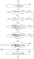
- FIG. 5 is a flowchart (part 1) illustrating an example of a process for determining representative UE candidates according to the first embodiment.
- the acquisition unit 130 acquires its own power supply information and its own processor information.
- the acquisition unit 130 acquires the power supply information and the processor information from the storage unit 110.
- the acquisition unit 130 acquires the power supply information and the processor information from an external device.
- the external device is a device that exists outside the UE 100.
- the external device is a cloud server.
- the external device is omitted in the diagram.
- Step S12 The determination unit 140 determines whether or not its own power supply method is external power supply based on its own power supply information. If the power supply method is external power supply, the process proceeds to step S13. If the power supply method is battery power supply, the process proceeds to step S21.
- step ST101 power supply information transmitted by other UEs is received. Therefore, the determination unit 140 can identify UEs that are operating with external power supply based on the power supply information received from other UEs.
- the determination unit 140 determines whether or not there is a UE having a CPU with a higher CPU operating frequency than the UE's own CPU operating frequency. Also, for example, the determination unit 140 determines whether or not there is a UE having a greater number of cores than the UE's own number of cores.
- step S15 If there is no UE with a processing capability higher than the processing capability of the own processor, the process proceeds to step S15. If there is a UE with a processing capability higher than the processing capability of the own processor, the process proceeds to step S27.
- Step S15 The determination unit 150 determines its own UE as a representative UE candidate.
- Step S16 The calculation unit 160 calculates a random number.
- Step S17 The communication unit 120 transmits information indicating that the UE is a representative UE candidate (hereinafter, representative UE candidate information) and a random number to the other UEs.
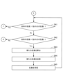
- Step S22 The determination unit 140 determines whether the remaining battery charge is equal to or greater than a predetermined threshold based on the remaining battery charge information. If the remaining battery charge is equal to or greater than the threshold, the process proceeds to step S23. If the remaining battery charge is less than the threshold, the process proceeds to step S27.
- Step S23 The determining unit 140 determines whether or not its own processor has sufficient processing power based on its own processor information. For example, the determining unit 140 determines that its own processor has sufficient processing power when the CPU operating frequency is equal to or greater than a predetermined threshold. Also, for example, the determining unit 140 determines that its own processor has sufficient processing power when the number of cores is equal to or greater than a predetermined threshold. If the own processor has sufficient processing power, the process proceeds to step S24. If the own processor does not have sufficient processing power, the process proceeds to step S27.
- Step S24 The determination unit 140 determines whether or not there is a UE that has the same processing capacity as the processing capacity of its own processor, based on the processor information received from the UE operating on external power supply. If the condition is met, the process proceeds to step S27. If the condition is not met, the process proceeds to step S25.
- Step S25 The determination unit 140 determines whether or not a UE with a processing capability higher than the processing capability of its own processor exists based on the processor information received from the UE operating on external power supply. If a UE with a processing capability higher than the processing capability of its own processor does not exist, the process proceeds to step S26. If a UE with a processing capability higher than the processing capability of its own processor exists, the process proceeds to step S27.
- Step S27 The decision unit 150 decides that its own UE will not become the representative UE.
- the representative UE candidate information and the random number are received. For example, if UE100a and 100b are determined as the representative UE candidates, UE100a receives the representative UE candidate information and the random number from UE100b. Also, UE100b receives the representative UE candidate information and the random number from UE100a.
- each of the multiple UEs determines whether or not it is a representative UE candidate based on the power supply method and the processing capacity of its processor. Also, when the power supply method is battery power supply, each of the multiple UEs determines whether or not it is a representative UE candidate based on the remaining battery capacity and the processing capacity of its processor.
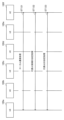
- FIG. 7 is a flowchart (part 1) illustrating an example of a process for determining a representative UE according to the first embodiment.
- the determination unit 140 determines whether or not the UE itself is a representative UE candidate. If the UE itself is a representative UE candidate, the process proceeds to step S32. If the UE itself is not a representative UE candidate, the process proceeds to step S34.
- Step S32 The determination unit 140 determines whether or not there is another representative UE candidate. Specifically, when representative UE candidate information is received, the determination unit 140 determines that there is another representative UE candidate. If there is another representative UE candidate, the process proceeds to step S41. If there is no another representative UE candidate, the process proceeds to step S33.
- Step S33 The determination unit 150 determines its own UE as the representative UE.
- Step S34 The determination unit 150 determines that its own UE will not become the representative UE.
- FIG. 8 is a flowchart (part 2) illustrating an example of the representative UE determination process according to the first embodiment.
- Step S41 When step S41 is executed after step S32, the determination unit 140 determines whether the random number transmitted in step S17 is greater than the random number received from another UE.
- step S41 When step S41 is executed after step S45, the determination unit 140 determines whether the random number calculated in step S43 is greater than the random number received in step S45. If the condition is met, the process proceeds to step S33, otherwise the process proceeds to step S42.
- Step S42 When step S41 is executed after step S32, the determination unit 140 determines whether the random number transmitted in step S17 is the same as the random number received from another UE. When step S41 is executed after step S45, the determination unit 140 determines whether the random number calculated in step S43 is the same as the random number received in step S45. If the condition is met, the process proceeds to step S43, otherwise the process proceeds to step S34.
- Step S43 The calculation unit 160 calculates a new random number.
- Step S44 The communication unit 120 transmits a new random number to the UEs among the representative UE candidates that transmitted the same random number value. Here, the UE receives a new random number. When the UE receives the new random number, the UE calculates a new random number. Then, the UE transmits the calculated random number.
- Step S45 The communication unit 120 receives a random number from the UE. Then, the process proceeds to step S41.
- the representative UE is determined in the communication system. In this manner, the representative UE is determined from among the representative UE candidates. When there are multiple representative UE candidates, the representative UE is determined using a random number.
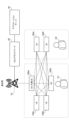
- FIG. 9 is a sequence diagram showing an example of processing performed by the representative UE in the first embodiment.
- the UE 100d collects the IP addresses and traffic types of the UEs 100a, 100b, and 100c.
- the UE 100d configures QoS and NSSAI.
- the UE 100d establishes a connection with the application server 30.
- the UE 100d executes a network address transformation (NAT) process. In the NAT process, traffic integration and traffic allocation are performed.
- NAT network address transformation
- a representative UE is determined from among multiple UEs.
- the representative UE then performs communication as a representative of the multiple UEs.
- the communication system can reduce the network load.
- steps S13 and S23 it is determined whether the processor itself has sufficient processing power.
- the determination unit 140 may determine whether the CPU usage rate of the processor itself is equal to or lower than a predetermined threshold value.
- Embodiment 2 Next, a description will be given of embodiment 2. In embodiment 2, differences from embodiment 1 will be mainly described. Furthermore, in embodiment 2, description of matters common to embodiment 1 will be omitted.
- a case where a representative UE is determined from among multiple UEs owned by one user is described.
- a case where a representative UE is determined from among multiple UEs owned by multiple users is described.
- the communication system includes UEs 100a to 100f.
- the UEs 100a to 100d belong to a user U1, and the UEs 100e and 100f belong to a user U2.
- the users U1 and U2 are in the same room.
- FIG. 11 is a diagram showing a flow of processes executed by a plurality of UEs in the second embodiment.
- the UEs 100a to 100f each execute a local communication process.
- the communication units of the UEs 100a to 100f transmit and receive power supply information and processor information to and from each other.
- the power supply information indicates battery power supply
- the communication units of the UEs 100a to 100f receive battery remaining amount information.
- Step ST122 The UEs 100a to 100f execute a process of determining representative UE candidates.
- the process of determining representative UE candidates is the same as that in step ST102, and therefore will not be described.
- Step ST123 The UEs 100a to 100f execute a process of determining a representative UE.
- the process of determining a representative UE is the same as that in step ST103, and therefore will not be described.
- the representative UE is determined in the communication system.
- the representative UE is assumed to be the UE 100d.
- FIG. 12 is a sequence diagram illustrating an example of processing performed by a representative UE in the second embodiment.
- the UE 100d collects the IP addresses and traffic types of the UEs 100a to 100c, 100e, and 100f.
- the UE 100d configures QoS and NSSAI.
- the UE 100d establishes a connection with the application server 30.
- the UE 100d executes the NAT process.
- a representative UE is determined from among multiple UEs owned by multiple users.
- the representative UE then performs communication as a representative of the multiple UEs.
- the communication system can reduce the network load.
- FIG. 13 is a sequence diagram showing an example in which a UE according to the second embodiment is added. Note that the base station 10 is omitted. It is assumed that the UE 100d is determined to be the representative UE from among the UEs 100a to 100d, and that the UEs 100e and 100f are added.
- Step ST141 The UE 100d establishes connections with the UEs 100e and 100f. This enables local communication between the UE 100d and the UEs 100e and 100f.
- Step ST142 The UE 100d collects the IP addresses and the traffic types of the UEs 100e and 100f.
- Step ST143 The UE 100d configures the QoS and the NSSAI for the UEs 100e and 100f.
- Step ST144 The UE 100d executes the NAT process.
- the above describes the case where UEs 100e and 100f owned by user U2 are added.
- the above content can be applied when a UE owned by user U2 is added. In other words, the above content can be applied when a different user adds a UE.
- the representative UE performs 5G communication as a representative of multiple UEs including multiple UEs (e.g., UEs 100a to 100c) and the new UE (e.g., UEs 100e and 100f). Because the new UE does not establish a connection individually, the network load is reduced.
- Base station 20 5G core network, 30 Application server, 100, 100a to 100f UE, 101 Processor, 102 Volatile storage device, 103 Non-volatile storage device, 110 Storage unit, 120 Communication unit, 130 Acquisition unit, 140 Determination unit, 150 Decision unit, 160 Calculation unit.
Landscapes
- Engineering & Computer Science (AREA)
- Computer Networks & Wireless Communication (AREA)
- Signal Processing (AREA)
- Mobile Radio Communication Systems (AREA)
Abstract
Description
本開示は、通信システムに関する。 This disclosure relates to a communication system.
第5世代移動通信システム(5G:5th Generation Mobile Communication System)が知られている。5Gでは、ユーザが使用する端末(UE:User Equipment)がネットワークを介して通信を行う場合、PDUセッションの確立、トラフィックの内容に応じたQoS(QFI:QoS Flow Identifier)の設定、スライス種別(NSSAI:Network Slice Selection Identifier)の設定が行われる。例えば、これらの内容は、非特許文献1、2に記載されている。 The 5th Generation Mobile Communication System (5G) is known. In 5G, when a terminal used by a user (UE: User Equipment) communicates via a network, a PDU session is established, QoS (QFI: QoS Flow Identifier) is set according to the contents of the traffic, and the slice type (NSSAI: Network Slice Selection Identifier) is set. For example, these contents are described in Non-Patent Documents 1 and 2.
ところで、ユーザがメタバースのようなサービスを受ける場合、ユーザが使用する複数のUEのそれぞれが、個別にネットワークに接続する。しかし、複数のUEのそれぞれが個別にネットワークに接続した場合、ネットワーク負荷が大きくなる。 When a user uses a service such as the metaverse, each of the multiple UEs used by the user connects to the network individually. However, when multiple UEs each connect to the network individually, the network load increases.
本開示の目的は、ネットワーク負荷を軽減することである。 The purpose of this disclosure is to reduce network load.
本開示の一態様に係る通信システムが提供される。通信システムは、ユーザが使用する複数の端末を含む。代表端末が、前記複数の端末の中から決定される。前記代表端末は、前記複数の端末の代表として、5G又はbeyond 5Gの通信を行う。 A communication system according to one aspect of the present disclosure is provided. The communication system includes a plurality of terminals used by users. A representative terminal is determined from among the plurality of terminals. The representative terminal performs 5G or beyond 5G communication as a representative of the plurality of terminals.
本開示によれば、ネットワーク負荷を軽減することができる。 This disclosure makes it possible to reduce network load.
以下、図面を参照しながら実施の形態を説明する。以下の実施の形態は、例にすぎず、本開示の範囲内で種々の変更が可能である。 Below, an embodiment will be described with reference to the drawings. The following embodiment is merely an example, and various modifications are possible within the scope of this disclosure.
実施の形態1.
図1は、実施の形態1の通信システムを示す図である。通信システムでは、5G又はbeyond 5Gの通信を行うことができる。例えば、beyond 5Gは、6Gである。以下の説明では、通信システムでは、5Gの通信が行われるものとする。
Embodiment 1.
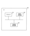
FIG. 1 is a diagram showing a communication system according to a first embodiment. In the communication system, 5G or beyond 5G communication can be performed. For example, beyond 5G is 6G. In the following description, it is assumed that 5G communication is performed in the communication system.
通信システムは、複数のUEを含む。図1では、複数のUEは、UE100a,100b,100c,100dである。図1は、4つのUEを示している。UEの数は、4つに限らない。
The communication system includes multiple UEs. In FIG. 1, the multiple UEs are
UE100a,100b,100c,100dは、一人のユーザが使用する端末である。例えば、UE100a,100b,100c,100dは、ゴーグル型のデバイス、グローブ型のデバイスなどである。例えば、ユーザは、UE100a,100b,100c,100dを用いて、メタバースにおけるサービスを受けることができる。 UE100a, 100b, 100c, and 100d are terminals used by a single user. For example, UE100a, 100b, 100c, and 100d are goggle-type devices, glove-type devices, and the like. For example, a user can receive services in the metaverse using UE100a, 100b, 100c, and 100d.
通信システムは、基地局10、5Gコアネットワーク20、及びアプリケーションサーバ30を含んでもよい。なお、5Gコアネットワーク20は、5Gユーザプレーンを含む。
The communication system may include a
実施の形態1を簡単に説明する。実施の形態1では、UE100a,100b,100c,100dの中から代表UEが、決定される。図1は、例として、UE100dが代表UEであることを示している。そして、代表UEは、複数のUEの代表として、5Gの通信を行う。詳細には、代表UEは、基地局10及び5Gコアネットワーク20を介して、アプリケーションサーバ30と通信する。このように、代表UEが複数のUEの代表として通信を行うことで、ネットワーク負荷が軽減される。
A brief description of the first embodiment will be given. In the first embodiment, a representative UE is determined from among UEs 100a, 100b, 100c, and 100d. FIG. 1 shows, as an example, that UE 100d is the representative UE. The representative UE performs 5G communication as a representative of multiple UEs. In detail, the representative UE communicates with the
以下、詳細に実施の形態1を説明する。また、UE100a,100b,100c,100dの総称を、UE100と呼ぶ。さらに、UEは、端末とも言う。 The first embodiment will be described in detail below. UEs 100a, 100b, 100c, and 100d are collectively referred to as UE 100. UE is also referred to as a terminal.
次に、UE100が有するハードウェアを説明する。
図2は、実施の形態1のUEが有するハードウェアを示す図である。UE100は、プロセッサ101、揮発性記憶装置102、及び不揮発性記憶装置103を有する。
Next, the hardware that UE 100 has will be described.
2 is a diagram showing hardware included in the UE of embodiment 1. The UE 100 includes a
プロセッサ101は、UE100全体を制御する。例えば、プロセッサ101は、CPU(Central Processing Unit)、FPGA(Field Programmable Gate Array)などである。プロセッサ101は、マルチプロセッサでもよい。また、UE100は、処理回路を有してもよい。
The
揮発性記憶装置102は、UE100の主記憶装置である。例えば、揮発性記憶装置102は、RAM(Random Access Memory)である。不揮発性記憶装置103は、UE100の補助記憶装置である。例えば、不揮発性記憶装置103は、SSD(Solid State Drive)である。
また、UE100は、バッテリを有する場合がある。
The
Furthermore, the UE 100 may have a battery.
次に、UE100が有する機能を説明する。
図3は、実施の形態1のUEの機能を示すブロック図である。UE100は、記憶部110、通信部120、取得部130、判定部140、決定部150、及び算出部160を有する。
Next, the functions of UE 100 will be described.
3 is a block diagram showing functions of the UE according to the embodiment 1. The
記憶部110は、揮発性記憶装置102又は不揮発性記憶装置103に確保した記憶領域として実現してもよい。
The
通信部120、取得部130、判定部140、決定部150、及び算出部160の一部又は全部は、処理回路によって実現してもよい。また、通信部120、取得部130、判定部140、決定部150、及び算出部160の一部又は全部は、プロセッサ101が実行するプログラムのモジュールとして実現してもよい。
The
記憶部110は、様々な情報を記憶する。
通信部120、取得部130、判定部140、決定部150、及び算出部160の機能は、後で詳細に説明する。
The
The functions of the
次に、複数のUEが実行する処理を簡単に説明する。
図4は、実施の形態1の複数のUEが実行する処理の流れを示す図である。
(ステップST101)UE100a,100b,100c,100dは、ローカル通信処理を実行する。詳細には、UE100a,100b,100c,100dは、サイドリンクによるP2P(Peer to Peer)接続を行う。
Next, the processing performed by multiple UEs will be briefly described.
FIG. 4 is a diagram showing a flow of processes executed by a plurality of UEs in the first embodiment.
(Step ST101) The
UE100a,100b,100c,100dの通信部は、互いに、給電情報及びプロセッサ情報を送受信する。給電情報は、給電方式を示す情報である。具体的には、給電情報は、外部給電又はバッテリ給電を示す。給電情報がバッテリ給電を示している場合、UE100a,100b,100c,100dの通信部は、バッテリ残量を示すバッテリ残量情報を受信する。プロセッサ情報は、プロセッサに関する情報である。例えば、プロセッサ情報は、CPU動作周波数、コア数、CPU使用率などである。 The communication units of UEs 100a, 100b, 100c, and 100d transmit and receive power supply information and processor information to and from each other. The power supply information is information indicating the power supply method. Specifically, the power supply information indicates external power supply or battery power supply. When the power supply information indicates battery power supply, the communication units of UEs 100a, 100b, 100c, and 100d receive battery remaining amount information indicating the remaining battery amount. The processor information is information related to the processor. For example, the processor information is the CPU operating frequency, the number of cores, the CPU usage rate, etc.
(ステップST102)UE100a,100b,100c,100dは、代表UE候補の決定処理を実行する。
(ステップST103)UE100a,100b,100c,100dは、代表UEの決定処理を実行する。
(Step ST102) The
(Step ST103) The
次に、代表UE候補の決定処理を、フローチャートを用いて説明する。
図5は、実施の形態1の代表UE候補の決定処理の例を示すフローチャート(その1)である。
(ステップS11)取得部130は、自身の給電情報と自身のプロセッサ情報とを取得する。例えば、取得部130は、当該給電情報と当該プロセッサ情報とを記憶部110から取得する。また、例えば、取得部130は、当該給電情報と当該プロセッサ情報とを外部装置から取得する。なお、外部装置は、UE100の外部に存在する装置である。例えば、外部装置は、クラウドサーバである。外部装置の図は、省略されている。
Next, the process of determining representative UE candidates will be described with reference to a flowchart.
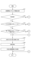
FIG. 5 is a flowchart (part 1) illustrating an example of a process for determining representative UE candidates according to the first embodiment.
(Step S11) The
(ステップS12)判定部140は、自身の給電情報に基づいて、自身の給電方式が外部給電であるか否かを判定する。給電方式が外部給電である場合、処理は、ステップS13に進む。給電方式がバッテリ給電である場合、処理は、ステップS21に進む。
(Step S12) The
(ステップS13)判定部140は、自身のプロセッサ情報に基づいて、自身のプロセッサが十分な処理能力を有しているか否かを判定する。例えば、判定部140は、CPU動作周波数が予め定められた閾値以上である場合、十分な処理能力を有していると判定する。また、例えば、判定部140は、コア数が予め定められた閾値以上である場合、十分な処理能力を有していると判定する。
自身のプロセッサが十分な処理能力を有している場合、処理は、ステップS14に進む。自身のプロセッサが十分な処理能力を有していない場合、処理は、ステップS27に進む。
(Step S13) The determining
If the own processor has sufficient processing power, the process proceeds to step S14, If the own processor does not have sufficient processing power, the process proceeds to step S27.
(ステップS14)判定部140は、外部給電で動作しているUEから受信したプロセッサ情報に基づいて、自身のプロセッサの処理能力よりも高い処理能力を有するUEが存在するか否かを判定する。
(Step S14) Based on the processor information received from the UE operating on external power supply, the
まず、ステップST101によって、他のUEが送信した給電情報が受信されている。そのため、判定部140は、他のUEから受信した給電情報に基づいて、外部給電で動作しているUEを特定できる。
First, in step ST101, power supply information transmitted by other UEs is received. Therefore, the
次に、判定処理の具体例を示す。例えば、判定部140は、自身のCPU動作周波数よりも高いCPU動作周波数のCPUを有するUEが存在するか否かを判定する。また、例えば、判定部140は、自身のコア数よりも多いコアを有するUEが存在するか否かを判定する。
Next, a specific example of the determination process is shown. For example, the
自身のプロセッサの処理能力よりも高い処理能力を有するUEが存在しない場合、処理は、ステップS15に進む。自身のプロセッサの処理能力よりも高い処理能力を有するUEが存在する場合、処理は、ステップS27に進む。 If there is no UE with a processing capability higher than the processing capability of the own processor, the process proceeds to step S15. If there is a UE with a processing capability higher than the processing capability of the own processor, the process proceeds to step S27.
(ステップS15)決定部150は、自身のUEを代表UE候補に決定する。
(ステップS16)算出部160は、乱数を算出する。
(ステップS17)通信部120は、代表UE候補であることを示す情報(以下、代表UE候補情報)と、乱数とを他のUEに送信する。
(Step S15) The
(Step S16) The
(Step S17) The
図6は、実施の形態1の代表UE候補の決定処理の例を示すフローチャート(その2)である。
(ステップS21)取得部130は、自身のバッテリのバッテリ残量を示すバッテリ残量情報を取得する。例えば、取得部130は、当該バッテリ残量情報を記憶部110から取得する。例えば、取得部130は、当該バッテリのバッテリ残量を計測するセンサから当該バッテリ残量情報を取得する。
FIG. 6 is a flowchart (part 2) illustrating an example of the process of determining representative UE candidates according to the first embodiment.
(Step S21) The
(ステップS22)判定部140は、当該バッテリ残量情報に基づいて、バッテリ残量が予め定められた閾値以上であるか否かを判定する。バッテリ残量が当該閾値以上である場合、処理は、ステップS23に進む。バッテリ残量が当該閾値未満である場合、処理は、ステップS27に進む。
(Step S22) The
(ステップS23)判定部140は、自身のプロセッサ情報に基づいて、自身のプロセッサが十分な処理能力を有しているか否かを判定する。例えば、判定部140は、CPU動作周波数が予め定められた閾値以上である場合、十分な処理能力を有していると判定する。また、例えば、判定部140は、コア数が予め定められた閾値以上である場合、十分な処理能力を有していると判定する。
自身のプロセッサが十分な処理能力を有している場合、処理は、ステップS24に進む。自身のプロセッサが十分な処理能力を有していない場合、処理は、ステップS27に進む。
(Step S23) The determining
If the own processor has sufficient processing power, the process proceeds to step S24. If the own processor does not have sufficient processing power, the process proceeds to step S27.
(ステップS24)判定部140は、外部給電で動作しているUEから受信したプロセッサ情報に基づいて、自身のプロセッサの処理能力と同じ処理能力を有するUEが存在するか否かを判定する。条件を満たす場合、処理は、ステップS27に進む。条件を満たさない場合、処理は、ステップS25に進む。
(Step S24) The
(ステップS25)判定部140は、外部給電で動作しているUEから受信したプロセッサ情報に基づいて、自身のプロセッサの処理能力よりも高い処理能力を有するUEが存在するか否かを判定する。自身のプロセッサの処理能力よりも高い処理能力を有するUEが存在しない場合、処理は、ステップS26に進む。自身のプロセッサの処理能力よりも高い処理能力を有するUEが存在する場合、処理は、ステップS27に進む。
(Step S25) The
(ステップS26)判定部140は、当該閾値以上のバッテリ残量を有し、かつバッテリ給電で動作しているUEから受信したプロセッサ情報に基づいて、自身のプロセッサの処理能力よりも高い処理能力を有するUEが存在するか否かを判定する。
なお、判定部140は、他のUEから受信した給電情報に基づいて、バッテリ給電で動作しているUEを特定できる。また、判定部140は、他のUEから受信したバッテリ残量情報に基づいて、当該閾値以上のバッテリ残量を有しているか否かを判定できる。
条件を満たす場合、処理は、ステップS27に進む。条件を満たさない場合、処理は、ステップS15に進む。
(Step S26) Based on the processor information received from a UE that has a remaining battery charge equal to or greater than the threshold and is operating on battery power, the
The
If the condition is met, the process proceeds to step S27, otherwise the process proceeds to step S15.
(ステップS27)決定部150は、自身のUEが代表UEにならないことを決定する。
(Step S27) The
他のUEが代表UE候補に決定された場合、代表UE候補情報及び乱数が受信される。例えば、UE100a,100bが代表UE候補に決定された場合、UE100aは、代表UE候補情報及び乱数をUE100bから受信する。また、UE100bは、代表UE候補情報及び乱数をUE100aから受信する。 If another UE is determined as the representative UE candidate, the representative UE candidate information and the random number are received. For example, if UE100a and 100b are determined as the representative UE candidates, UE100a receives the representative UE candidate information and the random number from UE100b. Also, UE100b receives the representative UE candidate information and the random number from UE100a.
このように、複数のUEのそれぞれは、給電方式と、プロセッサの処理能力とに基づいて、自身のUEが、代表UE候補であるか否かを判定する。また、複数のUEのそれぞれは、給電方式がバッテリ給電である場合、バッテリ残量と、プロセッサの処理能力とに基づいて、自身のUEが、代表UE候補であるか否かを判定する。 In this way, each of the multiple UEs determines whether or not it is a representative UE candidate based on the power supply method and the processing capacity of its processor. Also, when the power supply method is battery power supply, each of the multiple UEs determines whether or not it is a representative UE candidate based on the remaining battery capacity and the processing capacity of its processor.
次に、代表UEの決定処理を、フローチャートを用いて説明する。
図7は、実施の形態1の代表UEの決定処理の例を示すフローチャート(その1)である。
(ステップS31)判定部140は、自身のUEが代表UE候補であるか否かを判定する。自身のUEが代表UE候補である場合、処理は、ステップS32に進む。自身のUEが代表UE候補でない場合、処理は、ステップS34に進む。
Next, the representative UE determination process will be described with reference to a flowchart.
FIG. 7 is a flowchart (part 1) illustrating an example of a process for determining a representative UE according to the first embodiment.
(Step S31) The
(ステップS32)判定部140は、他に代表UE候補が存在するか否かを判定する。具体的には、判定部140は、代表UE候補情報が受信された場合、他に代表UE候補が存在すると判定する。
他に代表UE候補が存在する場合、処理は、ステップS41に進む。他に代表UE候補が存在しない場合、処理は、ステップS33に進む。
(Step S32) The
If there is another representative UE candidate, the process proceeds to step S41. If there is no another representative UE candidate, the process proceeds to step S33.
(ステップS33)決定部150は、自身のUEを代表UEに決定する。
(ステップS34)決定部150は、自身のUEが代表UEにならないことを決定する。
(Step S33) The
(Step S34) The
図8は、実施の形態1の代表UEの決定処理の例を示すフローチャート(その2)である。
(ステップS41)ステップS32の次にステップS41が実行される場合、判定部140は、ステップS17で送信された乱数が他のUEから受信した乱数よりも大きいか否かを判定する。ステップS45の次にステップS41が実行される場合、判定部140は、ステップS43で算出された乱数がステップS45で受信された乱数よりも大きいか否かを判定する。
条件が満たされる場合、処理は、ステップS33に進む。条件が満たされない場合、処理は、ステップS42に進む。
FIG. 8 is a flowchart (part 2) illustrating an example of the representative UE determination process according to the first embodiment.
(Step S41) When step S41 is executed after step S32, the
If the condition is met, the process proceeds to step S33, otherwise the process proceeds to step S42.
(ステップS42)ステップS32の次にステップS41が実行される場合、判定部140は、ステップS17で送信された乱数と、他のUEから受信した乱数とが同じであるか否かを判定する。ステップS45の次にステップS41が実行される場合、判定部140は、ステップS43で算出された乱数と、ステップS45で受信された乱数とが同じであるか否かを判定する。
条件が満たされる場合、処理は、ステップS43に進む。条件が満たされない場合、処理は、ステップS34に進む。
(Step S42) When step S41 is executed after step S32, the
If the condition is met, the process proceeds to step S43, otherwise the process proceeds to step S34.
(ステップS43)算出部160は、新たな乱数を算出する。
(ステップS44)通信部120は、代表UE候補のうち、同じ値の乱数を送信したUEに新たな乱数を送信する。
ここで、当該UEは、新たな乱数を受信する。当該UEは、新たな乱数を受信した場合、新たな乱数を算出する。そして、当該UEは、算出された乱数を送信する。
(Step S43) The
(Step S44) The
Here, the UE receives a new random number. When the UE receives the new random number, the UE calculates a new random number. Then, the UE transmits the calculated random number.
(ステップS45)通信部120は、乱数を当該UEから受信する。そして、処理は、ステップS41に進む。
代表UEの決定処理が終了した場合、通信システムでは、代表UEが決定される。このように、代表UEは、代表UE候補の中から決定される。代表UEは、複数の代表UE候補が存在する場合、乱数を用いて決定される。
(Step S45) The
When the process of determining the representative UE is completed, the representative UE is determined in the communication system. In this manner, the representative UE is determined from among the representative UE candidates. When there are multiple representative UE candidates, the representative UE is determined using a random number.
次に、代表UEが行う処理を、シーケンスを用いて説明する。また、代表UEは、UE100dとする。
図9は、実施の形態1の代表UEが行う処理の例を示すシーケンス図である。
(ステップST111)UE100dは、UE100a,100b,100cのIPアドレスとトラフィック種別とを収集する。
(ステップST112)UE100dは、QoSの設定、NSSAIの設定を行う。
(ステップST113)UE100dは、アプリケーションサーバ30との間でコネクションを確立する。
(ステップST114)UE100dは、NAT(Network Address Transformation)処理を実行する。NAT処理では、トラフィックの統合とトラフィックの割当てが行われる。
Next, a process performed by the representative UE will be described using a sequence. The representative UE is assumed to be the
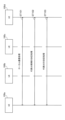
FIG. 9 is a sequence diagram showing an example of processing performed by the representative UE in the first embodiment.
(Step ST111) The
(Step ST112) The
(Step ST113) The
(Step ST114) The
実施の形態1によれば、通信システムでは、複数のUEの中から代表UEが、決定される。そして、代表UEは、複数のUEの代表として、通信を行う。そのため、通信システムは、ネットワーク負荷を軽減することができる。 According to the first embodiment, in the communication system, a representative UE is determined from among multiple UEs. The representative UE then performs communication as a representative of the multiple UEs. As a result, the communication system can reduce the network load.
ステップS13,23では、自身のプロセッサが十分な処理能力を有しているか否かが、判定された。ステップS13,23では、判定部140は、自身のCPU使用率が予め定められた閾値以下であるか否かを判定してもよい。
In steps S13 and S23, it is determined whether the processor itself has sufficient processing power. In steps S13 and S23, the
実施の形態2.
次に、実施の形態2を説明する。実施の形態2では、実施の形態1と相違する事項を主に説明する。そして、実施の形態2では、実施の形態1と共通する事項の説明を省略する。
Embodiment 2.
Next, a description will be given of embodiment 2. In embodiment 2, differences from embodiment 1 will be mainly described. Furthermore, in embodiment 2, description of matters common to embodiment 1 will be omitted.
実施の形態1では、一人のユーザが有する複数のUEの中から代表UEが決定される場合を説明した。実施の形態2では、複数のユーザが有する複数のUEの中から代表UEが決定される場合を説明する。 In the first embodiment, a case where a representative UE is determined from among multiple UEs owned by one user is described. In the second embodiment, a case where a representative UE is determined from among multiple UEs owned by multiple users is described.
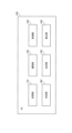
図10は、実施の形態2の通信システムを示す図である。通信システムは、UE100a~100fを含む。
UE100a~100dは、ユーザU1の所有物である。UE100e,100fは、ユーザU2の所有物である。例えば、ユーザU1とユーザU2とは、同じ部屋に存在する。
10 is a diagram showing a communication system according to embodiment 2. The communication system includes
The
図11は、実施の形態2の複数のUEが実行する処理の流れを示す図である。
(ステップST121)UE100a~100fは、ローカル通信処理を実行する。
UE100a~100fの通信部は、互いに、給電情報及びプロセッサ情報を送受信する。給電情報がバッテリ給電を示している場合、UE100a~100fの通信部は、バッテリ残量情報を受信する。
FIG. 11 is a diagram showing a flow of processes executed by a plurality of UEs in the second embodiment.
(Step ST121) The
The communication units of the UEs 100a to 100f transmit and receive power supply information and processor information to and from each other. When the power supply information indicates battery power supply, the communication units of the UEs 100a to 100f receive battery remaining amount information.
(ステップST122)UE100a~100fは、代表UE候補の決定処理を実行する。代表UE候補の決定処理は、ステップST102と同じなので、説明を省略する。
(ステップST123)UE100a~100fは、代表UEの決定処理を実行する。代表UEの決定処理は、ステップST103と同じなので、説明を省略する。
代表UEの決定処理が終了した場合、通信システムでは、代表UEが決定される。代表UEは、UE100dとする。
(Step ST122) The
(Step ST123) The
When the process of determining the representative UE is completed, the representative UE is determined in the communication system. The representative UE is assumed to be the
図12は、実施の形態2の代表UEが行う処理の例を示すシーケンス図である。
(ステップST131)UE100dは、UE100a~100c,100e,100fのIPアドレスとトラフィック種別とを収集する。
(ステップST132)UE100dは、QoSの設定、NSSAIの設定を行う。
(ステップST133)UE100dは、アプリケーションサーバ30との間でコネクションを確立する。
(ステップST134)UE100dは、NAT処理を実行する。
FIG. 12 is a sequence diagram illustrating an example of processing performed by a representative UE in the second embodiment.
(Step ST131) The
(Step ST132) The
(Step ST133) The
(Step ST134) The
実施の形態2によれば、通信システムでは、複数のユーザが有する複数のUEの中から代表UEが、決定される。そして、代表UEは、複数のUEの代表として、通信を行う。そのため、通信システムは、ネットワーク負荷を軽減することができる。 According to the second embodiment, in the communication system, a representative UE is determined from among multiple UEs owned by multiple users. The representative UE then performs communication as a representative of the multiple UEs. As a result, the communication system can reduce the network load.
また、代表UEが決定された後、新たなUEが代表UEと接続される場合を説明する。
図13は、実施の形態2のUEが追加された場合の例を示すシーケンス図である。なお、基地局10は、省略されている。
UE100a~100dの中からUE100dが代表UEに決定されたものとする。UE100e,100fが追加されたものとする。
In addition, a case where a new UE is connected to the representative UE after the representative UE is determined will be described.
13 is a sequence diagram showing an example in which a UE according to the second embodiment is added. Note that the
It is assumed that the
(ステップST141)UE100dは、UE100e,100fとコネクションを確立する。これにより、UE100dとUE100e,100fとの間では、ローカル通信が可能になる。
(ステップST142)UE100dは、UE100e,100fのIPアドレスとトラフィック種別とを収集する。
(ステップST143)UE100dは、UE100e,100fのために、QoSの設定、NSSAIの設定を行う。
(ステップST144)UE100dは、NAT処理を実行する。
(Step ST141) The
(Step ST142) The
(Step ST143) The
(Step ST144) The
なお、上記では、ユーザU2が有するUE100e,100fが追加される場合を説明した。上記の内容は、ユーザU2が有するUEが追加される場合に適用することができる。すなわち、上記の内容は、異なるユーザがUEを追加する場合に適用することができる。
Note that the above describes the case where
このように、代表UEは、代表UEが決定された後に新たなUEが追加された場合、複数のUE(例えば、UE100a~100c)と、新たなUE(例えば、UE100e,100f)と含む複数のUEの代表として、5Gの通信を行う。新たなUEが個別にコネクションを確立しないため、ネットワーク負荷が軽減される。
In this way, if a new UE is added after the representative UE has been determined, the representative UE performs 5G communication as a representative of multiple UEs including multiple UEs (e.g., UEs 100a to 100c) and the new UE (e.g.,
以上に説明した各実施の形態における特徴は、互いに適宜組み合わせることができる。 The features of each of the embodiments described above can be combined as appropriate.
10 基地局、 20 5Gコアネットワーク、 30 アプリケーションサーバ、 100,100a~100f UE、 101 プロセッサ、 102 揮発性記憶装置、 103 不揮発性記憶装置、 110 記憶部、 120 通信部、 130 取得部、 140 判定部、 150 決定部、 160 算出部。 10 Base station, 20 5G core network, 30 Application server, 100, 100a to 100f UE, 101 Processor, 102 Volatile storage device, 103 Non-volatile storage device, 110 Storage unit, 120 Communication unit, 130 Acquisition unit, 140 Determination unit, 150 Decision unit, 160 Calculation unit.
Claims (6)
代表端末が、前記複数の端末の中から決定され、
前記代表端末は、前記複数の端末の代表として、5G(5th Generation Mobile Communication System)又はbeyond 5Gの通信を行う、
通信システム。 A plurality of terminals used by users are included,
A representative terminal is determined from among the plurality of terminals;
The representative terminal performs 5G (5th Generation Mobile Communication System) or beyond 5G communication as a representative of the multiple terminals.
Communication systems.
前記代表端末は、前記代表端末候補の中から決定される、
請求項1に記載の通信システム。 Each of the plurality of terminals determines whether or not the terminal itself is a candidate for a representative terminal based on a power supply method and a processing capacity of a processor;
The representative terminal is determined from the representative terminal candidates.
The communication system according to claim 1 .
請求項2に記載の通信システム。 When the power supply method is battery power supply, each of the plurality of terminals determines whether or not the terminal itself is a candidate for the representative terminal based on a remaining battery charge and a processing capacity of the processor.
The communication system according to claim 2.
請求項2又は3に記載の通信システム。 When there are a plurality of representative terminal candidates, the representative terminal is determined using a random number.
A communication system according to claim 2 or 3.
請求項1から4のいずれか1項に記載の通信システム。 The plurality of terminals are terminals owned by a plurality of users.
A communication system according to any one of claims 1 to 4.
請求項1から5のいずれか1項に記載の通信システム。 When a new terminal is added after the representative terminal is determined, the representative terminal performs 5G or beyond 5G communication as a representative of the plurality of terminals including the plurality of terminals and the new terminal.
A communication system according to any one of claims 1 to 5.
Priority Applications (2)
| Application Number | Priority Date | Filing Date | Title |
|---|---|---|---|
| JP2024510256A JPWO2025041225A1 (en) | 2023-08-21 | 2023-08-21 | |
| PCT/JP2023/030001 WO2025041225A1 (en) | 2023-08-21 | 2023-08-21 | Communication system |
Applications Claiming Priority (1)
| Application Number | Priority Date | Filing Date | Title |
|---|---|---|---|
| PCT/JP2023/030001 WO2025041225A1 (en) | 2023-08-21 | 2023-08-21 | Communication system |
Publications (1)
| Publication Number | Publication Date |
|---|---|
| WO2025041225A1 true WO2025041225A1 (en) | 2025-02-27 |
Family
ID=94731813
Family Applications (1)
| Application Number | Title | Priority Date | Filing Date |
|---|---|---|---|
| PCT/JP2023/030001 Pending WO2025041225A1 (en) | 2023-08-21 | 2023-08-21 | Communication system |
Country Status (2)
| Country | Link |
|---|---|
| JP (1) | JPWO2025041225A1 (en) |
| WO (1) | WO2025041225A1 (en) |
Citations (4)
| Publication number | Priority date | Publication date | Assignee | Title |
|---|---|---|---|---|
| JP2002165272A (en) * | 2000-11-28 | 2002-06-07 | Nippon Telegr & Teleph Corp <Ntt> | Communication method and communication terminal |
| JP2014033371A (en) * | 2012-08-03 | 2014-02-20 | Sharp Corp | Information sharing system, terminal, switching method and program |
| WO2014184835A1 (en) * | 2013-05-15 | 2014-11-20 | 日本電気株式会社 | Communication system, communication timing control apparatus, connection control apparatus, communication timing control method, and computer readable medium |
| WO2022201555A1 (en) * | 2021-03-26 | 2022-09-29 | 株式会社Nttドコモ | Terminal, base station, and wireless communication system |
Family Cites Families (4)
| Publication number | Priority date | Publication date | Assignee | Title |
|---|---|---|---|---|
| JP4670646B2 (en) * | 2006-01-11 | 2011-04-13 | 株式会社豊田中央研究所 | Approach notification system |
| WO2016132719A1 (en) * | 2015-02-16 | 2016-08-25 | 日本電気株式会社 | Communication system, node device, communication terminal, key management method and non-temporary computer-readable medium in which program is stored |
| US20180041337A1 (en) * | 2015-02-16 | 2018-02-08 | Nec Corporation | Communication system, communication terminal, authentication method, and non-transitory computer readable medium storing program |
| JP2020174265A (en) * | 2019-04-10 | 2020-10-22 | ソニー株式会社 | Wireless communication device, communication control device and wireless communication system |
-
2023
- 2023-08-21 WO PCT/JP2023/030001 patent/WO2025041225A1/en active Pending
- 2023-08-21 JP JP2024510256A patent/JPWO2025041225A1/ja active Pending
Patent Citations (4)
| Publication number | Priority date | Publication date | Assignee | Title |
|---|---|---|---|---|
| JP2002165272A (en) * | 2000-11-28 | 2002-06-07 | Nippon Telegr & Teleph Corp <Ntt> | Communication method and communication terminal |
| JP2014033371A (en) * | 2012-08-03 | 2014-02-20 | Sharp Corp | Information sharing system, terminal, switching method and program |
| WO2014184835A1 (en) * | 2013-05-15 | 2014-11-20 | 日本電気株式会社 | Communication system, communication timing control apparatus, connection control apparatus, communication timing control method, and computer readable medium |
| WO2022201555A1 (en) * | 2021-03-26 | 2022-09-29 | 株式会社Nttドコモ | Terminal, base station, and wireless communication system |
Also Published As
| Publication number | Publication date |
|---|---|
| JPWO2025041225A1 (en) | 2025-02-27 |
Similar Documents
| Publication | Publication Date | Title |
|---|---|---|
| EP3097670B1 (en) | Methods, network node, systems, and computer program products for controlling usage of multi path tcp | |
| US10454827B2 (en) | Method and devices for controlling usage of multi-path TCP | |
| US9332583B2 (en) | Multipoint communication device and method of performing switching from multipoint communication to point-to-point communication | |
| CN114363963B (en) | Cloud primary UPF signaling plane load balancing selection method and system | |
| US10367893B1 (en) | Method and apparatus of performing peer-to-peer communication establishment | |
| US10051561B2 (en) | Methods and nodes for M2M communication | |
| CN113206894A (en) | DNS server discovery method and device, computer equipment and storage medium | |
| CN106998576A (en) | A kind of method and device for realizing access terminals switching | |
| CN110460641A (en) | Data transmission method, apparatus and system | |
| CN109219974A (en) | Base station equipment, terminal equipment and QoS control method | |
| CN106572132B (en) | Distributed chain building method, device and system | |
| CN103493399B (en) | The method and apparatus that data transfer simultaneously is provided based on two or more networks | |
| CN106027599B (en) | Data transmission channel establishing method, system and server | |
| US20160366195A1 (en) | Relayed Communication Channel Establishment | |
| US11363103B2 (en) | Dynamic user plane function (UPF) selection based on supported protocol type | |
| CN106101468B (en) | Method and device for determining transmission link | |
| US20160212052A1 (en) | Methods, systems, and computer readable media for balancing diameter message traffic received over long-lived diameter connections | |
| WO2025041225A1 (en) | Communication system | |
| CN104955125B (en) | Support dispatching method, terminal and the system of multiple types linking Internet | |
| CN108574615B (en) | Content transmission method, device and system based on multipath MPTCP | |
| CN107370647B (en) | Method for interconnecting local area internal controller systems and local area network system | |
| KR101058275B1 (en) | Communication terminal and its control method, P2P server system and its control method | |
| CN108632355B (en) | A home appliance network routing method, control terminal, readable storage medium and device | |
| CN112235840A (en) | Session terminal switching method, device, entity and system | |
| US8605649B2 (en) | Method for providing reliable communication session establishment in a communication infrastructure |
Legal Events
| Date | Code | Title | Description |
|---|---|---|---|
| ENP | Entry into the national phase |
Ref document number: 2024510256 Country of ref document: JP Kind code of ref document: A |
|
| WWE | Wipo information: entry into national phase |
Ref document number: 2024510256 Country of ref document: JP |
|
| 121 | Ep: the epo has been informed by wipo that ep was designated in this application |
Ref document number: 23949686 Country of ref document: EP Kind code of ref document: A1 |
|
| NENP | Non-entry into the national phase |
Ref country code: DE |