WO2025041214A1 - Système de distribution de charge, procédé de distribution de charge, dispositif de distribution de charge et programme de distribution de charge - Google Patents
Système de distribution de charge, procédé de distribution de charge, dispositif de distribution de charge et programme de distribution de charge Download PDFInfo
- Publication number
- WO2025041214A1 WO2025041214A1 PCT/JP2023/029914 JP2023029914W WO2025041214A1 WO 2025041214 A1 WO2025041214 A1 WO 2025041214A1 JP 2023029914 W JP2023029914 W JP 2023029914W WO 2025041214 A1 WO2025041214 A1 WO 2025041214A1
- Authority
- WO
- WIPO (PCT)
- Prior art keywords
- load balancing
- processing
- performance
- processing performance
- load distribution
- Prior art date
- Legal status (The legal status is an assumption and is not a legal conclusion. Google has not performed a legal analysis and makes no representation as to the accuracy of the status listed.)
- Pending
Links
Images




Classifications
-
- G—PHYSICS
- G06—COMPUTING OR CALCULATING; COUNTING
- G06F—ELECTRIC DIGITAL DATA PROCESSING
- G06F9/00—Arrangements for program control, e.g. control units
- G06F9/06—Arrangements for program control, e.g. control units using stored programs, i.e. using an internal store of processing equipment to receive or retain programs
- G06F9/46—Multiprogramming arrangements
- G06F9/50—Allocation of resources, e.g. of the central processing unit [CPU]
Definitions
- the present invention relates to a load balancing system, a load balancing method, a load balancing device, and a load balancing program that distribute tasks to be executed by devices.
- a load balancer or a task scheduler has been used as a method for allocating tasks to a plurality of devices (for example, CPU cores) mounted on a server or the like.
- the load is distributed at a predetermined ratio (see Non-Patent Document 1).
- the standard scheduler (Stop, Deadline, Realtime, Fair, Idle) of the Linux kernel ("Linux” is a registered trademark) controls the order of task execution based on process priority (see Non-Patent Document 2).
- the standard scheduler Simugate, Deadline, Realtime, Fair, Idle
- Linux kernel Linux kernel
- Linux kernel Linux kernel
- a common concept that higher operating frequencies have relatively larger capacity is introduced, and existing scheduling mechanisms are applied to heterogeneous cores (see Non-Patent Documents 3 and 4).
- the present invention was made in consideration of these points, and aims to balance the load on devices in a way that does not cause performance degradation of processes processed by devices with low processing performance, while at the same time using up the processing capacity of devices with high processing performance to improve resource utilization efficiency.
- the load balancing system is a load balancing system comprising a server having a device for processing a process, and a load balancing device for distributing loads to a plurality of processes operating on the server, wherein the server comprises a processing performance collection unit for collecting the processing performance values of each device with different performance for executing the process as data for each predetermined function that affects the processing performance values, and a processing execution unit for executing the processing of the process according to the load balancing ratio calculated by the load balancing device, and the load balancing device comprises a data aggregation unit for acquiring the processing performance values of the devices with different performance from the server and storing them in a storage unit for each predetermined function that affects the processing performance values, a load balancing ratio determination unit for calculating the processing performance values of the devices with different performance as a performance ratio, which is the processing performance value of the device relative to the lowest processing performance value of the predetermined function, and for executing a load balancing ratio determination process for determining a load
- the present invention in device load balancing, it is possible to prevent performance degradation of processes processed by devices with low processing performance, while at the same time making full use of the processing capacity of devices with high processing performance, thereby improving resource utilization efficiency.
- FIG. 1 is a diagram showing an overall configuration of a load balancing system including a load balancing device according to an embodiment of the present invention
- 11 is a diagram for explaining each function that affects a processing performance value.
- FIG. 4 is a flowchart showing the flow of processing executed by the load balancing system according to the present embodiment.
- FIG. 11 is a diagram showing the overall configuration of a load balancing system according to a second embodiment.
- 10 is a flowchart showing the flow of processing executed by the load balancing system according to the second embodiment.
- FIG. 2 is a hardware configuration diagram illustrating an example of a computer that realizes the functions of the load balancing device according to the embodiment.
- the load distribution system In order to solve the above-mentioned problem of the decrease in resource utilization efficiency due to the upper limit of the processing speed of the low-performance core, the load distribution system according to this embodiment (the load distribution system according to the first embodiment) increases or decreases the load allocation to the process running on the device (CPU core) according to the processing capacity of the device. Specifically, this load distribution system collects information on the processing performance value of each device, determines the load distribution ratio (allocation ratio) based on the data, and executes the allocation. In this way, tasks are allocated at an appropriate ratio according to the performance of each device (CPU core), so that the performance degradation of the process processed by the device with low processing performance does not occur, and at the same time, the resource utilization efficiency can be improved.
- the number of cores allocated to a process is controlled for an application that can be increased or decreased by scaling out/in, scaling up/down, etc.
- existing technologies such as the Linux kernel task scheduler and the load balancer for Pods by Kubernetes Service ("Kubernetes" is a registered trademark) distribute the load evenly without considering the processing power of each CPU core. The following description is based on the above (1) to (3).
- the device is mainly a CPU (CPU core), but the device in this embodiment is not limited to a CPU (CPU core) and can also be applied to accelerators such as a GPU (Graphics Processing Unit), an FPGA (Field Programmable Gate Array), and an XPU.
- CPU Central Processing Unit
- FPGA Field Programmable Gate Array
- XPU XPU
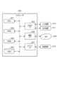
- FIG. 1 is a diagram showing the overall configuration of a load balancing system 1000 including a load balancing apparatus 1 according to this embodiment. As shown in FIG. 1, a load balancing apparatus 1 is communicatively connected to each server 2 equipped with a device (CPU core) to be controlled.
- a load balancing apparatus 1 is communicatively connected to each server 2 equipped with a device (CPU core) to be controlled.
- the control unit is responsible for all the processing executed by the server 2, and is composed of a processing performance collection unit 21 and a processing execution unit 22.
- the processing performance collection unit 21 collects processing performance values of devices (here, CPU cores) with different performance for executing processes as data for each predetermined function that affects the processing performance value.
- Processing performance values are defined as two types, for example, “throughput” and “time (delay) from task arrival to processing completion,” and either one or a combination of these values (for example, a linear combination) is used depending on the process characteristics and SLA (Service Level Agreement).
- the processing performance collection unit 21 collects some or all of the data related to certain functions that affect the processing performance values shown below (e.g., sibling cores, P-State, C-State, core type, high temperature operation, power saving mode, performance conflicts due to core sharing).
- certain functions e.g., sibling cores, P-State, C-State, core type, high temperature operation, power saving mode, performance conflicts due to core sharing.
- Sibling cores are a feature that assigns multiple threads to one core.
- HyperThreading a technology used in Intel products, divides one physical core into two logical cores (front and back).
- the server 2 has this sibling core function, for example, in the example shown by reference numeral 201 in FIG. 2, a processing performance value is obtained when both logical cores (front/back) using HyperThreading are executing processing, and a processing performance value is obtained when only one of the logical cores (front/back) is executing processing.
- ⁇ P-State P-State is a function that dynamically changes the operating frequency by setting a specific combination of operating frequency and operating voltage to the CPU core. As shown by reference numeral 202 in Fig. 2, the processing performance value is obtained in a state "P0" where the CPU operating frequency and voltage are maximum, and in a state (P8) where the CPU frequency is, for example, 800-2100 (MHz) and controlled in 100 (MHz) intervals.
- ⁇ C-State C-State is a function that defines the idle state (power saving mode) of the CPU. It is defined from C0 (active state) to Cn, and the larger the value of n, the longer the time required to return (the time to transition to C0). The return time (delay) from C0 to Cn is obtained as the processing performance value.
- Core type For example, assume that out of a server equipped with four CPU cores, two are high-performance cores and two are low-performance cores (see reference numeral 203 in FIG. 2). In this way, when two types of CPU cores with different processing performance are set in one server, the processing performance value for each type of core group installed is obtained. For example, this is realized by a technology equipped with multiple types of processors, such as big.LITTLE, developed by ARM (registered trademark).
- this function suppresses performance and transitions to a low-performance mode when the CPU core becomes too hot (see reference numeral 204 in FIG. 2).
- the processing performance values of each CPU core in both the normal state and the performance suppression state due to high temperature are acquired.
- EPP Electronic Performance Preference
- EPB Intel performance and energy bias hint
- the processing performance collection unit 21 is configured in advance with information to be acquired regarding specific functions that are factors that affect the processing performance value of each server 2, and acquires information regarding each processing performance value before the start of actual processing or at specific time intervals.
- the process execution unit 22 is a functional unit that processes application processes, and executes the allocated processes according to the load distribution ratio determined by the load distribution device 1 according to the performance of the CPU cores, for example.
- the load balancing device 1 obtains information regarding processing performance values from each server 2, determines the load balancing ratio for processes running on a device (CPU core) based on the processing capacity of that device (CPU core), and performs load balancing for the application processes.
- the load balancing device 1 is configured by a computer including a control unit, an input/output unit (both of which are not shown), and a storage unit 14 .
- the input/output unit inputs and outputs information between each server 2, etc.
- This input/output unit is composed of a communication interface that transmits and receives information via a communication line, and an input/output interface that inputs and outputs information between an input device such as a keyboard (not shown) and an output device such as a monitor.
- the storage unit 14 is composed of a hard disk, a flash memory, a RAM (Random Access Memory), or the like.
- This memory unit 14 stores information regarding processing performance values obtained from each server 2, and programs (load balancing programs) for executing each function of the control unit, and also temporarily stores information necessary for processing by the control unit.
- the control unit is responsible for all the processing performed by the load balancing device 1, and is composed of a data aggregation unit 11, a load balancing ratio determination unit 12, and a load balancing execution unit 13.
- the data aggregation unit 11 acquires processing performance values of devices (CPU cores) with different performance from each server 2, and stores the processing performance values in the storage unit 14 for each predetermined function that affects the processing performance value.
- the data aggregator 11 also monitors the processing performance values of the CPU cores acquired from each server 2, and periodically (at a predetermined time interval) outputs instruction information to the load distribution ratio determiner 12 to execute a load distribution ratio determination process.
- the data aggregator 11 detects a predetermined change in data that dynamically changes as the processing performance values of the CPU cores, it outputs instruction information to the load distribution ratio determiner 12 to execute a load distribution ratio determination process.
- a predetermined change is detected is, for example, when there is a change in settings in each function that requires recalculation of the processing performance values, or when there is a fluctuation in the processing performance values that is equal to or greater than a predetermined threshold value due to the change in settings.
- the load distribution ratio determination unit 12 calculates a load distribution ratio for each process based on the data of the processing performance values of the CPU cores aggregated by the data aggregation unit 11 .
- the load distribution ratio determination unit 12 calculates the processing performance value of the CPU core as a scalar value, and calculates the load distribution ratio for each process using that value.
- the load distribution ratio determination unit 12 defines the lowest processing capacity value for each function as "1.0,” calculates the processing performance value of a device (CPU core) with different performance relative to that as a performance ratio, and determines the load distribution ratio for the device (CPU core) with different performance according to the calculated performance ratio.
- the load distribution ratio determination unit 12 multiplies the performance ratios of the processing performance values calculated for each function.
- the processing performance values are defined for two types: “throughput” and “time (delay) from task arrival to processing completion.” Depending on the process characteristics and SLA, either one or a combination of the two values is used. The method of calculating the load distribution ratio for each function will be described below.
- the operating frequency set in the P-State is 800-2100 (MHz), can be controlled in 100 (MHz) increments, and the processing power increases or decreases in proportion to the CPU frequency.
- the minimum operating frequency of 800 (MHz) is defined as "1.0", and for every 100 (MHz) higher, it increases by "0.125", and at the maximum of 2100 (MHz), it is defined as "2.625”.
- the processing performance value may be calculated by determining the processing performance ratio for the governor (e.g., Powersave, Performance) applied to each CPU core. For example, if the processing performance ratio of Powersave and Performance is 3 times, the CPU processing performance values are "1.0" and "3.0", respectively.
- the load distribution ratio determination unit 12 calculates the performance ratio of the device (CPU core) for each function.
- the load distribution ratio determination unit 12 multiplies the performance ratios of the processing performance values calculated for each function. If the ratio difference becomes larger than a predetermined threshold value due to the multiplication of performance ratios based on multiple processing performance values, specifically, if the difference in the allocation ratio between one CPU core and another CPU core becomes large, for example, 1:15, by multiplying the performance ratios of the processing performance values of multiple functions, the predetermined threshold value may be set to, for example, 10, and if the difference in performance ratios exceeds 10, the load distribution ratios may be set to 1:10 for all. Also, a correction may be made by multiplying by a coefficient according to the magnitude of the calculated difference.
- the load distribution ratio determination unit 12 may set a coefficient for each function according to the functions to be combined, correct the performance ratio of the processing performance value of each function by multiplying the performance ratio by the coefficient, and then multiply the multiple functions.
- the processing performance value of each function may be corrected as necessary, taking into account excessive effects when multiple functions are combined.
- the load balancing execution unit 13 distributes the load for the application processes according to the load balancing ratio determined by the load balancing ratio determination unit 12, and causes the processing execution unit 22 of the server 2 to execute the processing.
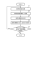
- FIG. 3 is a flowchart showing the flow of processing executed by the load balancing system 1000 according to this embodiment.
- the processing performance collection unit 21 of the server 2 collects processing performance values related to each function of the device (CPU core) (step S1). Specifically, the processing performance collection unit 21 collects some or all of the data (processing performance values) related to each function that affects the processing performance value (e.g., sibling cores, P-State, C-State, core type, high temperature operation, power saving mode, performance contention due to core sharing). It is set in advance which function's data related to the processing performance value the processing performance collection unit 21 will acquire.
- the data collected by the processing performance collection unit 21 is “throughput” and “time (delay) from task arrival to processing completion,” and either one or a combination of these values is collected as processing performance value data depending on the process characteristics and SLA.
- the processing performance collection unit 21 transmits the collected processing performance value data to the load distribution device 1.
- the data aggregation unit 11 of the load distribution device 1 aggregates the data of the CPU core processing performance values acquired from each server 2 and stores the data in the storage unit 14 (step S2).
- the data aggregation unit 11 saves data for each function that affects the processing performance value.
- the load distribution ratio determination unit 12 of the load distribution device 1 calculates the performance ratio of devices (CPU cores) with different performance in a specified function based on the data of the processing performance values of the CPU cores aggregated by the data aggregation unit 11, and determines the load distribution ratio for each process based on the calculated performance ratio (step S3).
- the load balancing ratio determination unit 12 defines the lowest processing performance value for each function as 1.0, calculates the ratio of each processing performance value to this (performance ratio: scalar value), and uses this value to calculate the task allocation ratio (load balancing ratio). For example, if the processing performance value of CPU core No. 0 is "1.0" and the processing performance value of CPU core No. 1 is "1.5", the allocation ratio (load balancing rate) is 1.0:1.5.
- the load balancing execution unit 13 of the load balancing device 1 assigns the load balancing ratio (task allocation ratio) to the process of the application according to the load balancing ratio determined by the load balancing ratio determination unit 12, and causes the process execution unit 22 of each server 2 to execute the assignment (step S4).
- the data aggregation unit 11 of the load distribution device 1 judges whether a predetermined change in the processing performance value has been detected or whether a predetermined time has elapsed (step S5). If the data aggregation unit 11 detects a predetermined change in the processing performance value or if the predetermined time has elapsed (step S5 ⁇ Yes), the process returns to step S1 and continues. If the data aggregation unit 11 does not detect a predetermined change or if the predetermined time has not elapsed (step S5 ⁇ No), the process ends.
- the load distribution device 1 dynamically updates the load distribution ratio by re-executing the processes of steps S1 to S5 at a predetermined time interval, thereby enabling the load distribution device 1 to track temporary changes in processing power and always allocate tasks with an optimal load distribution ratio.
- FIG. 4 is a diagram showing the overall configuration of a load balancing system 1000A according to the second embodiment.
- the difference from the load balancing system 1000 of this embodiment shown in Figure 1 is that each server 2 is equipped with a metrics collection unit 23, and the data aggregation unit 11 ( Figure 1) of the load balancing device 1 has become a data aggregation unit 11A.
- the load balancing system 1000A performs processing that focuses on the fact that, depending on the nature of a process, the processing performance of a CPU core may be unrelated to the performance of an application. This is because if load balancing control is performed on such a process, it is conceivable that performance degradation may occur due to an unintended bottleneck. For example, if there is a bottleneck in the memory transfer of data, and load balancing control is performed to increase the amount of data allocated to that process, performance degradation may occur regardless of the processing performance of the CPU core. Therefore, a function is added that collects various metrics (e.g., resource usage rate) and determines whether or not the process should be controlled.
- various metrics e.g., resource usage rate
- Each server 2 has a metrics collection unit 23.
- the metrics collection unit 23 collects metrics (e.g., resource usage) that are set in advance according to the process to be load balanced and expected bottlenecks. The metrics collection unit 23 then transmits the collected metrics to the load balancer 1.
- metrics e.g., resource usage
- the data aggregator 11A of the load balancer 1 acquires information on preset metrics from the metrics collector 23 of the server 2, and determines, based on a predetermined logic, whether or not to treat a process as a control target. Even if the data aggregator 11A performs load balancing control based on the collected metrics, the process of an application that does not depend on the processing performance of a CPU core is excluded from the control target. For example, when a bottleneck is assumed in data memory transfer, even if the task allocation amount to the CPU core is increased, the resource usage rate (CPU usage rate) will not increase. In such a case, since there is no need to increase the task allocation amount, the process of the application is removed from the control target.
- CPU usage rate resource usage rate
- the predetermined logic at this time is that when the task allocation amount increases, if the resource usage rate (CPU usage rate) does not increase accordingly, the process is removed from the control target.
- the data aggregation unit 11A is preset with a predetermined logic corresponding to the metrics.
- ⁇ Processing flow> 5 is a flowchart showing the flow of processing executed by the load balancing system 1000A according to the second embodiment. Processing that is the same as that of the load balancing system 1000 according to the present embodiment shown in FIG. 3 is given the same step number and description thereof will be omitted.
- step S10 the metrics collection unit 23 of each server 2 collects preset metrics (e.g., resource usage rates) and transmits them to the load distribution device 1. Then, the data aggregation unit 11A of the load distribution device 1 determines, based on the collected metrics, whether or not to control the process of the application. If it is determined that the process of the application is to be controlled (step S10 ⁇ Yes), the process proceeds to the next step S1 and continues the process from step S1 onward. On the other hand, if it is determined that the process of the application is not to be controlled (step S10 ⁇ No), the process ends without performing load balancing control.
- preset metrics e.g., resource usage rates
- the load balancing system 1000A can suppress unnecessary control of processes that do not affect the performance of applications even if differences in processing performance occur between CPU cores.
- the load balancing device 1 has been described as including a "data aggregator” and a “load balancing ratio determiner".
- the "data aggregator” and the "load balancing ratio determiner” may be included in, for example, a load balancer or a task scheduler.
- the load balancer has the functions of a "data aggregation unit” and a "load balancing ratio determination unit".
- the "data aggregation unit” and the “load balancing ratio determination unit” may be implemented outside the load balancer and operate in cooperation with the load balancer.
- the load balancer may also be a logical distribution function unit such as a service mesh in Kubernetes.
- the load balancer functions as a load balancing device.
- the "load balancing ratio determination unit” utilizes a weighted request distribution function that is generally provided in a load balancer.
- the "processing performance collection unit” and the “processing execution unit” are executed on server 2, and the process that constitutes the “processing execution unit” may be a process (bare metal process) that runs directly on the OS of server 2, or it may be a VM or a container.
- the task scheduler of the OS is provided with the functions of a "data aggregation unit” and a "load balancing ratio determination unit.”
- the "data aggregation unit” and the “load balancing ratio determination unit” may be implemented outside the task scheduler and operate in cooperation with the task scheduler.
- the task scheduler functions as a load balancing device.
- the "load distribution execution unit” is the OS task scheduler itself, and issues instructions to each CPU core to execute a process so that the ratio corresponds to the processing performance value of the CPU core.
- the "processing performance collection unit” and the “processing execution unit” are executed on server 2, and the process that constitutes the “processing execution unit” may be a process (bare metal process) that runs directly on the OS of server 2, or it may be a VM or a container.
- a core allocation function may be newly added to a system in which a load balancer or a task scheduler, or both, operate. This core allocation function may operate in a server 2 having a "processing performance collection unit” and a “processing execution unit”, or may be implemented externally and operate in cooperation with the load balancer, the scheduler, or the server 2. In the third modification, the core allocation function functions as a load distribution device.
- the core allocation function executes a “data aggregation unit”, a “load distribution ratio determination unit”, and a “load distribution execution unit”.
- the core allocation function allocates a group of processes running on the server 2 to each CPU core using functions such as taskset or cgroups so that the load corresponds to the ratio of the processing performance values of the CPU cores.
- the process that is the entity of the "processing execution unit” may be a process that runs directly on the OS of the server 2 (a bare metal process), or may be a VM (virtual machine) or a container.
- the device of this embodiment is not limited to a CPU core, and can also be applied to a GPU, FPGA, etc.
- the "processing performance value of the CPU core" is replaced with the "processing performance value of the GPU, FPGA, etc.” to execute the processing.
- GPUs and FPGAs have a function for controlling the P-State (clock frequency), it is possible to perform load balancing control based on the difference in processing performance value due to this P-State.
- the load balancing device 1 is realized by a computer 900 having a configuration as shown in FIG. 6 is a hardware configuration diagram showing an example of a computer 900 that realizes the functions of the load balancing device 1 according to this embodiment.
- the computer 900 has a CPU 901, a ROM (Read Only Memory) 902, a RAM 903, a HDD (Hard Disk Drive) 904, an input/output I/F (Interface) 905, a communication I/F 906, and a media I/F 907.
- the CPU 901 operates based on a program (load balancing program) stored in the ROM 902 or HDD 904, and performs control using a control unit (data aggregation unit, load balancing ratio determination unit, load balancing execution unit).
- the ROM 902 stores a boot program executed by the CPU 901 when the computer 900 is started, programs related to the hardware of the computer 900, etc.
- the CPU 901 controls an input device 910 such as a mouse or keyboard, and an output device 911 such as a display or printer, via an input/output I/F 905.
- the CPU 901 acquires data from the input device 910 via the input/output I/F 905, and outputs generated data to the output device 911.
- a GPU Graphics Processing Unit
- a processor may be used as a processor together with the CPU 901.
- the HDD 904 stores the programs executed by the CPU 901 and the data used by the programs.
- the communication I/F 906 receives data from other devices via a communication network (e.g., NW (Network) 920) and outputs the data to the CPU 901, and also transmits data generated by the CPU 901 to other devices via the communication network.
- NW Network
- the media I/F 907 reads a program (load balancing program) or data stored in the recording medium 912 and outputs it to the CPU 901 via the RAM 903.
- the CPU 901 loads a program related to the target processing from the recording medium 912 onto the RAM 903 via the media I/F 907, and executes the loaded program.
- the recording medium 912 is an optical recording medium such as a DVD (Digital Versatile Disc) or a PD (Phase change rewritable Disk), a magneto-optical recording medium such as an MO (Magneto Optical disk), a magnetic recording medium, a semiconductor memory, etc.
- the CPU 901 of the computer 900 executes a load balancing program loaded onto the RAM 903, thereby realizing the functions of the load balancing device 1.
- the data in the RAM 903 is stored in the HDD 904.
- the CPU 901 reads and executes a program related to the target processing from the recording medium 912.
- the CPU 901 may read a program related to the target processing from another device via the communication network (NW 920).
- the load balancing system according to the present invention is a load balancing system 1000 including a server 2 having a device for processing a process, and a load balancing device 1 that performs load balancing to a plurality of processes operating on the server 2, in which the server 2 includes a processing performance collection unit 21 that collects the processing performance values of each device with different performance for executing the process as data for each predetermined function that affects the processing performance value, and a processing execution unit 22 that executes the processing of the process in accordance with a load balancing ratio calculated by the load balancing device 1, and the load balancing device 1 includes a data aggregation unit 11 that acquires the processing performance values of the devices with different performance from the server 2 and stores them in a memory unit 14 for each predetermined function that affects the processing performance value, a load balancing ratio determination unit 12 that calculates the processing performance values of the devices with different performance as a performance ratio
- the load balancing system 1000 can balance the load at an appropriate ratio according to the performance of each device, preventing performance degradation of processes processed by devices with low processing performance, while at the same time making full use of the processing capacity of devices with high processing performance, thereby improving resource utilization efficiency.
- the data aggregation unit 11 monitors the processing performance values of devices with different performance for each specified function, and when a specified change is detected and at each specified time interval, instructs the load balancing ratio determination unit 12 to execute the load balancing ratio determination process.
- the load balancing system 1000 can track temporary changes in the processing power of each device and balance the load at an appropriate ratio.
- the load balancing ratio determination unit 12 determines the load balancing ratio by multiplying the performance ratios calculated for each function.
- the load balancing system 1000 can distribute the load at an appropriate ratio corresponding to the multiple functions, even if devices with different process processing capabilities have multiple specified functions.
- the server 2 further includes a metrics collection unit 23 that collects metrics that serve as an indicator of whether or not a process should be subject to load balancing control, and the data aggregation unit 11A of the load balancing device 1 acquires metric information and determines, based on a predetermined logic, whether or not a process should be subject to load balancing control.
- the load balancing system 1000A can suppress unnecessary control of processes that do not affect the performance of applications even if differences in processing performance occur between CPU cores.
Landscapes
- Engineering & Computer Science (AREA)
- Software Systems (AREA)
- Theoretical Computer Science (AREA)
- Physics & Mathematics (AREA)
- General Engineering & Computer Science (AREA)
- General Physics & Mathematics (AREA)
- Multi Processors (AREA)
Abstract
L'invention concerne un serveur (2) d'un système de distribution de charge (1000) qui comprend : une unité de collecte de performances de traitement (21) qui collecte des valeurs de performances de traitement de dispositifs qui diffèrent en matière de performances en termes d'exécution d'un processus ; et une unité de traitement (22) qui exécute un traitement de processus. Un dispositif de distribution de charge (1) comprend : une unité d'agrégation de données (11) qui acquiert les valeurs de performances de traitement auprès du serveur et les stocke dans une unité de stockage (14) pour chaque fonction prescrite ; une unité de détermination de rapport de distribution de charge (12) qui calcule, pour une fonction prescrite, un rapport de performances qui est une valeur de performances de traitement d'un dispositif par rapport à la valeur de performances de traitement la plus faible, et détermine un rapport de distribution de charge selon le rapport de performances calculé ; et une unité d'exécution de distribution de charge (13) qui distribue un traitement de processus au dispositif selon le rapport de distribution de charge déterminé.
Priority Applications (2)
| Application Number | Priority Date | Filing Date | Title |
|---|---|---|---|
| PCT/JP2023/029914 WO2025041214A1 (fr) | 2023-08-21 | 2023-08-21 | Système de distribution de charge, procédé de distribution de charge, dispositif de distribution de charge et programme de distribution de charge |
| JP2025541176A JPWO2025041214A1 (fr) | 2023-08-21 | 2023-08-21 |
Applications Claiming Priority (1)
| Application Number | Priority Date | Filing Date | Title |
|---|---|---|---|
| PCT/JP2023/029914 WO2025041214A1 (fr) | 2023-08-21 | 2023-08-21 | Système de distribution de charge, procédé de distribution de charge, dispositif de distribution de charge et programme de distribution de charge |
Publications (1)
| Publication Number | Publication Date |
|---|---|
| WO2025041214A1 true WO2025041214A1 (fr) | 2025-02-27 |
Family
ID=94731644
Family Applications (1)
| Application Number | Title | Priority Date | Filing Date |
|---|---|---|---|
| PCT/JP2023/029914 Pending WO2025041214A1 (fr) | 2023-08-21 | 2023-08-21 | Système de distribution de charge, procédé de distribution de charge, dispositif de distribution de charge et programme de distribution de charge |
Country Status (2)
| Country | Link |
|---|---|
| JP (1) | JPWO2025041214A1 (fr) |
| WO (1) | WO2025041214A1 (fr) |
Citations (1)
| Publication number | Priority date | Publication date | Assignee | Title |
|---|---|---|---|---|
| WO2023084777A1 (fr) * | 2021-11-15 | 2023-05-19 | 日本電信電話株式会社 | Dispositif de gestion de planification, procédé de gestion de planification et programme |
-
2023
- 2023-08-21 JP JP2025541176A patent/JPWO2025041214A1/ja active Pending
- 2023-08-21 WO PCT/JP2023/029914 patent/WO2025041214A1/fr active Pending
Patent Citations (1)
| Publication number | Priority date | Publication date | Assignee | Title |
|---|---|---|---|---|
| WO2023084777A1 (fr) * | 2021-11-15 | 2023-05-19 | 日本電信電話株式会社 | Dispositif de gestion de planification, procédé de gestion de planification et programme |
Non-Patent Citations (2)
| Title |
|---|
| KATAYAMA, MINORU: "A Study of Constructing Distributed Real-time Systems", IEICE TECHNICAL REPORT, SSE, IEICE, JP, vol. 98, no. 84 (SSE98-33), 29 May 1998 (1998-05-29), JP, pages 1 - 8, XP009561325 * |
| SONODA JUN: "Automatic Optimized Load Balancing for Parallel FDTD Computation on Heterogeneous PC Cluster", IEICE TRANSACTIONS B, IEICE, JP, vol. J87-B, no. 5, 1 May 2004 (2004-05-01), JP, pages 760 - 764, XP093281388, ISSN: 1344-4697 * |
Also Published As
| Publication number | Publication date |
|---|---|
| JPWO2025041214A1 (fr) | 2025-02-27 |
Similar Documents
| Publication | Publication Date | Title |
|---|---|---|
| US9104498B2 (en) | Maximizing server utilization within a datacenter | |
| CN102282543B (zh) | 信息处理装置和信息处理方法 | |
| EP2430538B1 (fr) | Attribution de niveaux de puissance de système informatique en réponse à des accords sur les niveaux de service | |
| US9183016B2 (en) | Adaptive task scheduling of Hadoop in a virtualized environment | |
| CN102958166B (zh) | 一种资源分配方法及资源管理平台 | |
| US9268394B2 (en) | Virtualized application power budgeting | |
| EP2430541B1 (fr) | Gestion de puissance dans un système informatique multiprocesseur | |
| US8381215B2 (en) | Method and system for power-management aware dispatcher | |
| US20150295970A1 (en) | Method and device for augmenting and releasing capacity of computing resources in real-time stream computing system | |
| CN107003887A (zh) | Cpu超载设置和云计算工作负荷调度机构 | |
| US20200382443A1 (en) | System and Methods for Sharing Memory Subsystem Resources Among Datacenter Applications | |
| Salehi et al. | Preemption-aware energy management in virtualized data centers | |
| CN111459622A (zh) | 调度虚拟cpu的方法、装置、计算机设备和存储介质 | |
| US20120042322A1 (en) | Hybrid Program Balancing | |
| CN103414784A (zh) | 支持应急模式的云计算资源调度方法 | |
| US8245229B2 (en) | Temporal batching of I/O jobs | |
| Stillwell et al. | Dynamic fractional resource scheduling versus batch scheduling | |
| CN112114967B (zh) | 一种基于服务优先级的gpu资源预留方法 | |
| Kalogeraki et al. | Dynamic migration algorithms for distributed object systems | |
| JP2014206805A (ja) | 制御装置 | |
| Ali et al. | Power aware NUMA scheduler in vmware's esxi hypervisor | |
| TWI917044B (zh) | 運算資源管理方法以及運算裝置 | |
| Ren et al. | Developing power‐aware scheduling mechanisms for computing systems virtualized by Xen | |
| CN121144013A (zh) | 全局资源优化配置方法、装置、电子设备及可读存储介质 | |
| Elijorde et al. | CloudSwitch: A State-aware Monitoring Strategy Towards Energy-efficient and Performance-aware Cloud Data Centers. |
Legal Events
| Date | Code | Title | Description |
|---|---|---|---|
| 121 | Ep: the epo has been informed by wipo that ep was designated in this application |
Ref document number: 23949675 Country of ref document: EP Kind code of ref document: A1 |
|
| ENP | Entry into the national phase |
Ref document number: 2025541176 Country of ref document: JP Kind code of ref document: A |
|
| WWE | Wipo information: entry into national phase |
Ref document number: 2025541176 Country of ref document: JP |
|
| NENP | Non-entry into the national phase |
Ref country code: DE |