WO2025041214A1 - Load distribution system, load distribution method, load distribution device, and load distribution program - Google Patents
Load distribution system, load distribution method, load distribution device, and load distribution program Download PDFInfo
- Publication number
- WO2025041214A1 WO2025041214A1 PCT/JP2023/029914 JP2023029914W WO2025041214A1 WO 2025041214 A1 WO2025041214 A1 WO 2025041214A1 JP 2023029914 W JP2023029914 W JP 2023029914W WO 2025041214 A1 WO2025041214 A1 WO 2025041214A1
- Authority
- WO
- WIPO (PCT)
- Prior art keywords
- load balancing
- processing
- performance
- processing performance
- load distribution
- Prior art date
- Legal status (The legal status is an assumption and is not a legal conclusion. Google has not performed a legal analysis and makes no representation as to the accuracy of the status listed.)
- Pending
Links
Images




Classifications
-
- G—PHYSICS
- G06—COMPUTING OR CALCULATING; COUNTING
- G06F—ELECTRIC DIGITAL DATA PROCESSING
- G06F9/00—Arrangements for program control, e.g. control units
- G06F9/06—Arrangements for program control, e.g. control units using stored programs, i.e. using an internal store of processing equipment to receive or retain programs
- G06F9/46—Multiprogramming arrangements
- G06F9/50—Allocation of resources, e.g. of the central processing unit [CPU]
Definitions
- the present invention relates to a load balancing system, a load balancing method, a load balancing device, and a load balancing program that distribute tasks to be executed by devices.
- a load balancer or a task scheduler has been used as a method for allocating tasks to a plurality of devices (for example, CPU cores) mounted on a server or the like.
- the load is distributed at a predetermined ratio (see Non-Patent Document 1).
- the standard scheduler (Stop, Deadline, Realtime, Fair, Idle) of the Linux kernel ("Linux” is a registered trademark) controls the order of task execution based on process priority (see Non-Patent Document 2).
- the standard scheduler Simugate, Deadline, Realtime, Fair, Idle
- Linux kernel Linux kernel
- Linux kernel Linux kernel
- a common concept that higher operating frequencies have relatively larger capacity is introduced, and existing scheduling mechanisms are applied to heterogeneous cores (see Non-Patent Documents 3 and 4).
- the present invention was made in consideration of these points, and aims to balance the load on devices in a way that does not cause performance degradation of processes processed by devices with low processing performance, while at the same time using up the processing capacity of devices with high processing performance to improve resource utilization efficiency.
- the load balancing system is a load balancing system comprising a server having a device for processing a process, and a load balancing device for distributing loads to a plurality of processes operating on the server, wherein the server comprises a processing performance collection unit for collecting the processing performance values of each device with different performance for executing the process as data for each predetermined function that affects the processing performance values, and a processing execution unit for executing the processing of the process according to the load balancing ratio calculated by the load balancing device, and the load balancing device comprises a data aggregation unit for acquiring the processing performance values of the devices with different performance from the server and storing them in a storage unit for each predetermined function that affects the processing performance values, a load balancing ratio determination unit for calculating the processing performance values of the devices with different performance as a performance ratio, which is the processing performance value of the device relative to the lowest processing performance value of the predetermined function, and for executing a load balancing ratio determination process for determining a load
- the present invention in device load balancing, it is possible to prevent performance degradation of processes processed by devices with low processing performance, while at the same time making full use of the processing capacity of devices with high processing performance, thereby improving resource utilization efficiency.
- FIG. 1 is a diagram showing an overall configuration of a load balancing system including a load balancing device according to an embodiment of the present invention
- 11 is a diagram for explaining each function that affects a processing performance value.
- FIG. 4 is a flowchart showing the flow of processing executed by the load balancing system according to the present embodiment.
- FIG. 11 is a diagram showing the overall configuration of a load balancing system according to a second embodiment.
- 10 is a flowchart showing the flow of processing executed by the load balancing system according to the second embodiment.
- FIG. 2 is a hardware configuration diagram illustrating an example of a computer that realizes the functions of the load balancing device according to the embodiment.
- the load distribution system In order to solve the above-mentioned problem of the decrease in resource utilization efficiency due to the upper limit of the processing speed of the low-performance core, the load distribution system according to this embodiment (the load distribution system according to the first embodiment) increases or decreases the load allocation to the process running on the device (CPU core) according to the processing capacity of the device. Specifically, this load distribution system collects information on the processing performance value of each device, determines the load distribution ratio (allocation ratio) based on the data, and executes the allocation. In this way, tasks are allocated at an appropriate ratio according to the performance of each device (CPU core), so that the performance degradation of the process processed by the device with low processing performance does not occur, and at the same time, the resource utilization efficiency can be improved.
- the number of cores allocated to a process is controlled for an application that can be increased or decreased by scaling out/in, scaling up/down, etc.
- existing technologies such as the Linux kernel task scheduler and the load balancer for Pods by Kubernetes Service ("Kubernetes" is a registered trademark) distribute the load evenly without considering the processing power of each CPU core. The following description is based on the above (1) to (3).
- the device is mainly a CPU (CPU core), but the device in this embodiment is not limited to a CPU (CPU core) and can also be applied to accelerators such as a GPU (Graphics Processing Unit), an FPGA (Field Programmable Gate Array), and an XPU.
- CPU Central Processing Unit
- FPGA Field Programmable Gate Array
- XPU XPU
- FIG. 1 is a diagram showing the overall configuration of a load balancing system 1000 including a load balancing apparatus 1 according to this embodiment. As shown in FIG. 1, a load balancing apparatus 1 is communicatively connected to each server 2 equipped with a device (CPU core) to be controlled.
- a load balancing apparatus 1 is communicatively connected to each server 2 equipped with a device (CPU core) to be controlled.
- the control unit is responsible for all the processing executed by the server 2, and is composed of a processing performance collection unit 21 and a processing execution unit 22.
- the processing performance collection unit 21 collects processing performance values of devices (here, CPU cores) with different performance for executing processes as data for each predetermined function that affects the processing performance value.
- Processing performance values are defined as two types, for example, “throughput” and “time (delay) from task arrival to processing completion,” and either one or a combination of these values (for example, a linear combination) is used depending on the process characteristics and SLA (Service Level Agreement).
- the processing performance collection unit 21 collects some or all of the data related to certain functions that affect the processing performance values shown below (e.g., sibling cores, P-State, C-State, core type, high temperature operation, power saving mode, performance conflicts due to core sharing).
- certain functions e.g., sibling cores, P-State, C-State, core type, high temperature operation, power saving mode, performance conflicts due to core sharing.
- Sibling cores are a feature that assigns multiple threads to one core.
- HyperThreading a technology used in Intel products, divides one physical core into two logical cores (front and back).
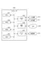
- the server 2 has this sibling core function, for example, in the example shown by reference numeral 201 in FIG. 2, a processing performance value is obtained when both logical cores (front/back) using HyperThreading are executing processing, and a processing performance value is obtained when only one of the logical cores (front/back) is executing processing.
- ⁇ P-State P-State is a function that dynamically changes the operating frequency by setting a specific combination of operating frequency and operating voltage to the CPU core. As shown by reference numeral 202 in Fig. 2, the processing performance value is obtained in a state "P0" where the CPU operating frequency and voltage are maximum, and in a state (P8) where the CPU frequency is, for example, 800-2100 (MHz) and controlled in 100 (MHz) intervals.
- ⁇ C-State C-State is a function that defines the idle state (power saving mode) of the CPU. It is defined from C0 (active state) to Cn, and the larger the value of n, the longer the time required to return (the time to transition to C0). The return time (delay) from C0 to Cn is obtained as the processing performance value.
- Core type For example, assume that out of a server equipped with four CPU cores, two are high-performance cores and two are low-performance cores (see reference numeral 203 in FIG. 2). In this way, when two types of CPU cores with different processing performance are set in one server, the processing performance value for each type of core group installed is obtained. For example, this is realized by a technology equipped with multiple types of processors, such as big.LITTLE, developed by ARM (registered trademark).
- this function suppresses performance and transitions to a low-performance mode when the CPU core becomes too hot (see reference numeral 204 in FIG. 2).
- the processing performance values of each CPU core in both the normal state and the performance suppression state due to high temperature are acquired.
- EPP Electronic Performance Preference
- EPB Intel performance and energy bias hint
- the processing performance collection unit 21 is configured in advance with information to be acquired regarding specific functions that are factors that affect the processing performance value of each server 2, and acquires information regarding each processing performance value before the start of actual processing or at specific time intervals.
- the process execution unit 22 is a functional unit that processes application processes, and executes the allocated processes according to the load distribution ratio determined by the load distribution device 1 according to the performance of the CPU cores, for example.
- the load balancing device 1 obtains information regarding processing performance values from each server 2, determines the load balancing ratio for processes running on a device (CPU core) based on the processing capacity of that device (CPU core), and performs load balancing for the application processes.
- the load balancing device 1 is configured by a computer including a control unit, an input/output unit (both of which are not shown), and a storage unit 14 .
- the input/output unit inputs and outputs information between each server 2, etc.
- This input/output unit is composed of a communication interface that transmits and receives information via a communication line, and an input/output interface that inputs and outputs information between an input device such as a keyboard (not shown) and an output device such as a monitor.
- the storage unit 14 is composed of a hard disk, a flash memory, a RAM (Random Access Memory), or the like.
- This memory unit 14 stores information regarding processing performance values obtained from each server 2, and programs (load balancing programs) for executing each function of the control unit, and also temporarily stores information necessary for processing by the control unit.
- the control unit is responsible for all the processing performed by the load balancing device 1, and is composed of a data aggregation unit 11, a load balancing ratio determination unit 12, and a load balancing execution unit 13.
- the data aggregation unit 11 acquires processing performance values of devices (CPU cores) with different performance from each server 2, and stores the processing performance values in the storage unit 14 for each predetermined function that affects the processing performance value.
- the data aggregator 11 also monitors the processing performance values of the CPU cores acquired from each server 2, and periodically (at a predetermined time interval) outputs instruction information to the load distribution ratio determiner 12 to execute a load distribution ratio determination process.
- the data aggregator 11 detects a predetermined change in data that dynamically changes as the processing performance values of the CPU cores, it outputs instruction information to the load distribution ratio determiner 12 to execute a load distribution ratio determination process.
- a predetermined change is detected is, for example, when there is a change in settings in each function that requires recalculation of the processing performance values, or when there is a fluctuation in the processing performance values that is equal to or greater than a predetermined threshold value due to the change in settings.
- the load distribution ratio determination unit 12 calculates a load distribution ratio for each process based on the data of the processing performance values of the CPU cores aggregated by the data aggregation unit 11 .
- the load distribution ratio determination unit 12 calculates the processing performance value of the CPU core as a scalar value, and calculates the load distribution ratio for each process using that value.
- the load distribution ratio determination unit 12 defines the lowest processing capacity value for each function as "1.0,” calculates the processing performance value of a device (CPU core) with different performance relative to that as a performance ratio, and determines the load distribution ratio for the device (CPU core) with different performance according to the calculated performance ratio.
- the load distribution ratio determination unit 12 multiplies the performance ratios of the processing performance values calculated for each function.
- the processing performance values are defined for two types: “throughput” and “time (delay) from task arrival to processing completion.” Depending on the process characteristics and SLA, either one or a combination of the two values is used. The method of calculating the load distribution ratio for each function will be described below.
- the operating frequency set in the P-State is 800-2100 (MHz), can be controlled in 100 (MHz) increments, and the processing power increases or decreases in proportion to the CPU frequency.
- the minimum operating frequency of 800 (MHz) is defined as "1.0", and for every 100 (MHz) higher, it increases by "0.125", and at the maximum of 2100 (MHz), it is defined as "2.625”.
- the processing performance value may be calculated by determining the processing performance ratio for the governor (e.g., Powersave, Performance) applied to each CPU core. For example, if the processing performance ratio of Powersave and Performance is 3 times, the CPU processing performance values are "1.0" and "3.0", respectively.
- the load distribution ratio determination unit 12 calculates the performance ratio of the device (CPU core) for each function.
- the load distribution ratio determination unit 12 multiplies the performance ratios of the processing performance values calculated for each function. If the ratio difference becomes larger than a predetermined threshold value due to the multiplication of performance ratios based on multiple processing performance values, specifically, if the difference in the allocation ratio between one CPU core and another CPU core becomes large, for example, 1:15, by multiplying the performance ratios of the processing performance values of multiple functions, the predetermined threshold value may be set to, for example, 10, and if the difference in performance ratios exceeds 10, the load distribution ratios may be set to 1:10 for all. Also, a correction may be made by multiplying by a coefficient according to the magnitude of the calculated difference.
- the load distribution ratio determination unit 12 may set a coefficient for each function according to the functions to be combined, correct the performance ratio of the processing performance value of each function by multiplying the performance ratio by the coefficient, and then multiply the multiple functions.
- the processing performance value of each function may be corrected as necessary, taking into account excessive effects when multiple functions are combined.
- the load balancing execution unit 13 distributes the load for the application processes according to the load balancing ratio determined by the load balancing ratio determination unit 12, and causes the processing execution unit 22 of the server 2 to execute the processing.
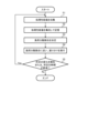
- FIG. 3 is a flowchart showing the flow of processing executed by the load balancing system 1000 according to this embodiment.
- the processing performance collection unit 21 of the server 2 collects processing performance values related to each function of the device (CPU core) (step S1). Specifically, the processing performance collection unit 21 collects some or all of the data (processing performance values) related to each function that affects the processing performance value (e.g., sibling cores, P-State, C-State, core type, high temperature operation, power saving mode, performance contention due to core sharing). It is set in advance which function's data related to the processing performance value the processing performance collection unit 21 will acquire.
- the data collected by the processing performance collection unit 21 is “throughput” and “time (delay) from task arrival to processing completion,” and either one or a combination of these values is collected as processing performance value data depending on the process characteristics and SLA.
- the processing performance collection unit 21 transmits the collected processing performance value data to the load distribution device 1.
- the data aggregation unit 11 of the load distribution device 1 aggregates the data of the CPU core processing performance values acquired from each server 2 and stores the data in the storage unit 14 (step S2).
- the data aggregation unit 11 saves data for each function that affects the processing performance value.
- the load distribution ratio determination unit 12 of the load distribution device 1 calculates the performance ratio of devices (CPU cores) with different performance in a specified function based on the data of the processing performance values of the CPU cores aggregated by the data aggregation unit 11, and determines the load distribution ratio for each process based on the calculated performance ratio (step S3).
- the load balancing ratio determination unit 12 defines the lowest processing performance value for each function as 1.0, calculates the ratio of each processing performance value to this (performance ratio: scalar value), and uses this value to calculate the task allocation ratio (load balancing ratio). For example, if the processing performance value of CPU core No. 0 is "1.0" and the processing performance value of CPU core No. 1 is "1.5", the allocation ratio (load balancing rate) is 1.0:1.5.
- the load balancing execution unit 13 of the load balancing device 1 assigns the load balancing ratio (task allocation ratio) to the process of the application according to the load balancing ratio determined by the load balancing ratio determination unit 12, and causes the process execution unit 22 of each server 2 to execute the assignment (step S4).
- the data aggregation unit 11 of the load distribution device 1 judges whether a predetermined change in the processing performance value has been detected or whether a predetermined time has elapsed (step S5). If the data aggregation unit 11 detects a predetermined change in the processing performance value or if the predetermined time has elapsed (step S5 ⁇ Yes), the process returns to step S1 and continues. If the data aggregation unit 11 does not detect a predetermined change or if the predetermined time has not elapsed (step S5 ⁇ No), the process ends.
- the load distribution device 1 dynamically updates the load distribution ratio by re-executing the processes of steps S1 to S5 at a predetermined time interval, thereby enabling the load distribution device 1 to track temporary changes in processing power and always allocate tasks with an optimal load distribution ratio.
- FIG. 4 is a diagram showing the overall configuration of a load balancing system 1000A according to the second embodiment.
- the difference from the load balancing system 1000 of this embodiment shown in Figure 1 is that each server 2 is equipped with a metrics collection unit 23, and the data aggregation unit 11 ( Figure 1) of the load balancing device 1 has become a data aggregation unit 11A.
- the load balancing system 1000A performs processing that focuses on the fact that, depending on the nature of a process, the processing performance of a CPU core may be unrelated to the performance of an application. This is because if load balancing control is performed on such a process, it is conceivable that performance degradation may occur due to an unintended bottleneck. For example, if there is a bottleneck in the memory transfer of data, and load balancing control is performed to increase the amount of data allocated to that process, performance degradation may occur regardless of the processing performance of the CPU core. Therefore, a function is added that collects various metrics (e.g., resource usage rate) and determines whether or not the process should be controlled.
- various metrics e.g., resource usage rate
- Each server 2 has a metrics collection unit 23.
- the metrics collection unit 23 collects metrics (e.g., resource usage) that are set in advance according to the process to be load balanced and expected bottlenecks. The metrics collection unit 23 then transmits the collected metrics to the load balancer 1.
- metrics e.g., resource usage
- the data aggregator 11A of the load balancer 1 acquires information on preset metrics from the metrics collector 23 of the server 2, and determines, based on a predetermined logic, whether or not to treat a process as a control target. Even if the data aggregator 11A performs load balancing control based on the collected metrics, the process of an application that does not depend on the processing performance of a CPU core is excluded from the control target. For example, when a bottleneck is assumed in data memory transfer, even if the task allocation amount to the CPU core is increased, the resource usage rate (CPU usage rate) will not increase. In such a case, since there is no need to increase the task allocation amount, the process of the application is removed from the control target.
- CPU usage rate resource usage rate
- the predetermined logic at this time is that when the task allocation amount increases, if the resource usage rate (CPU usage rate) does not increase accordingly, the process is removed from the control target.
- the data aggregation unit 11A is preset with a predetermined logic corresponding to the metrics.
- ⁇ Processing flow> 5 is a flowchart showing the flow of processing executed by the load balancing system 1000A according to the second embodiment. Processing that is the same as that of the load balancing system 1000 according to the present embodiment shown in FIG. 3 is given the same step number and description thereof will be omitted.
- step S10 the metrics collection unit 23 of each server 2 collects preset metrics (e.g., resource usage rates) and transmits them to the load distribution device 1. Then, the data aggregation unit 11A of the load distribution device 1 determines, based on the collected metrics, whether or not to control the process of the application. If it is determined that the process of the application is to be controlled (step S10 ⁇ Yes), the process proceeds to the next step S1 and continues the process from step S1 onward. On the other hand, if it is determined that the process of the application is not to be controlled (step S10 ⁇ No), the process ends without performing load balancing control.
- preset metrics e.g., resource usage rates
- the load balancing system 1000A can suppress unnecessary control of processes that do not affect the performance of applications even if differences in processing performance occur between CPU cores.
- the load balancing device 1 has been described as including a "data aggregator” and a “load balancing ratio determiner".
- the "data aggregator” and the "load balancing ratio determiner” may be included in, for example, a load balancer or a task scheduler.
- the load balancer has the functions of a "data aggregation unit” and a "load balancing ratio determination unit".
- the "data aggregation unit” and the “load balancing ratio determination unit” may be implemented outside the load balancer and operate in cooperation with the load balancer.
- the load balancer may also be a logical distribution function unit such as a service mesh in Kubernetes.
- the load balancer functions as a load balancing device.
- the "load balancing ratio determination unit” utilizes a weighted request distribution function that is generally provided in a load balancer.
- the "processing performance collection unit” and the “processing execution unit” are executed on server 2, and the process that constitutes the “processing execution unit” may be a process (bare metal process) that runs directly on the OS of server 2, or it may be a VM or a container.
- the task scheduler of the OS is provided with the functions of a "data aggregation unit” and a "load balancing ratio determination unit.”
- the "data aggregation unit” and the “load balancing ratio determination unit” may be implemented outside the task scheduler and operate in cooperation with the task scheduler.
- the task scheduler functions as a load balancing device.
- the "load distribution execution unit” is the OS task scheduler itself, and issues instructions to each CPU core to execute a process so that the ratio corresponds to the processing performance value of the CPU core.
- the "processing performance collection unit” and the “processing execution unit” are executed on server 2, and the process that constitutes the “processing execution unit” may be a process (bare metal process) that runs directly on the OS of server 2, or it may be a VM or a container.
- a core allocation function may be newly added to a system in which a load balancer or a task scheduler, or both, operate. This core allocation function may operate in a server 2 having a "processing performance collection unit” and a “processing execution unit”, or may be implemented externally and operate in cooperation with the load balancer, the scheduler, or the server 2. In the third modification, the core allocation function functions as a load distribution device.
- the core allocation function executes a “data aggregation unit”, a “load distribution ratio determination unit”, and a “load distribution execution unit”.
- the core allocation function allocates a group of processes running on the server 2 to each CPU core using functions such as taskset or cgroups so that the load corresponds to the ratio of the processing performance values of the CPU cores.
- the process that is the entity of the "processing execution unit” may be a process that runs directly on the OS of the server 2 (a bare metal process), or may be a VM (virtual machine) or a container.
- the device of this embodiment is not limited to a CPU core, and can also be applied to a GPU, FPGA, etc.
- the "processing performance value of the CPU core" is replaced with the "processing performance value of the GPU, FPGA, etc.” to execute the processing.
- GPUs and FPGAs have a function for controlling the P-State (clock frequency), it is possible to perform load balancing control based on the difference in processing performance value due to this P-State.
- the load balancing device 1 is realized by a computer 900 having a configuration as shown in FIG. 6 is a hardware configuration diagram showing an example of a computer 900 that realizes the functions of the load balancing device 1 according to this embodiment.
- the computer 900 has a CPU 901, a ROM (Read Only Memory) 902, a RAM 903, a HDD (Hard Disk Drive) 904, an input/output I/F (Interface) 905, a communication I/F 906, and a media I/F 907.
- the CPU 901 operates based on a program (load balancing program) stored in the ROM 902 or HDD 904, and performs control using a control unit (data aggregation unit, load balancing ratio determination unit, load balancing execution unit).
- the ROM 902 stores a boot program executed by the CPU 901 when the computer 900 is started, programs related to the hardware of the computer 900, etc.
- the CPU 901 controls an input device 910 such as a mouse or keyboard, and an output device 911 such as a display or printer, via an input/output I/F 905.
- the CPU 901 acquires data from the input device 910 via the input/output I/F 905, and outputs generated data to the output device 911.
- a GPU Graphics Processing Unit
- a processor may be used as a processor together with the CPU 901.
- the HDD 904 stores the programs executed by the CPU 901 and the data used by the programs.
- the communication I/F 906 receives data from other devices via a communication network (e.g., NW (Network) 920) and outputs the data to the CPU 901, and also transmits data generated by the CPU 901 to other devices via the communication network.
- NW Network
- the media I/F 907 reads a program (load balancing program) or data stored in the recording medium 912 and outputs it to the CPU 901 via the RAM 903.
- the CPU 901 loads a program related to the target processing from the recording medium 912 onto the RAM 903 via the media I/F 907, and executes the loaded program.
- the recording medium 912 is an optical recording medium such as a DVD (Digital Versatile Disc) or a PD (Phase change rewritable Disk), a magneto-optical recording medium such as an MO (Magneto Optical disk), a magnetic recording medium, a semiconductor memory, etc.
- the CPU 901 of the computer 900 executes a load balancing program loaded onto the RAM 903, thereby realizing the functions of the load balancing device 1.
- the data in the RAM 903 is stored in the HDD 904.
- the CPU 901 reads and executes a program related to the target processing from the recording medium 912.
- the CPU 901 may read a program related to the target processing from another device via the communication network (NW 920).
- the load balancing system according to the present invention is a load balancing system 1000 including a server 2 having a device for processing a process, and a load balancing device 1 that performs load balancing to a plurality of processes operating on the server 2, in which the server 2 includes a processing performance collection unit 21 that collects the processing performance values of each device with different performance for executing the process as data for each predetermined function that affects the processing performance value, and a processing execution unit 22 that executes the processing of the process in accordance with a load balancing ratio calculated by the load balancing device 1, and the load balancing device 1 includes a data aggregation unit 11 that acquires the processing performance values of the devices with different performance from the server 2 and stores them in a memory unit 14 for each predetermined function that affects the processing performance value, a load balancing ratio determination unit 12 that calculates the processing performance values of the devices with different performance as a performance ratio
- the load balancing system 1000 can balance the load at an appropriate ratio according to the performance of each device, preventing performance degradation of processes processed by devices with low processing performance, while at the same time making full use of the processing capacity of devices with high processing performance, thereby improving resource utilization efficiency.
- the data aggregation unit 11 monitors the processing performance values of devices with different performance for each specified function, and when a specified change is detected and at each specified time interval, instructs the load balancing ratio determination unit 12 to execute the load balancing ratio determination process.
- the load balancing system 1000 can track temporary changes in the processing power of each device and balance the load at an appropriate ratio.
- the load balancing ratio determination unit 12 determines the load balancing ratio by multiplying the performance ratios calculated for each function.
- the load balancing system 1000 can distribute the load at an appropriate ratio corresponding to the multiple functions, even if devices with different process processing capabilities have multiple specified functions.
- the server 2 further includes a metrics collection unit 23 that collects metrics that serve as an indicator of whether or not a process should be subject to load balancing control, and the data aggregation unit 11A of the load balancing device 1 acquires metric information and determines, based on a predetermined logic, whether or not a process should be subject to load balancing control.
- the load balancing system 1000A can suppress unnecessary control of processes that do not affect the performance of applications even if differences in processing performance occur between CPU cores.
Landscapes
- Engineering & Computer Science (AREA)
- Software Systems (AREA)
- Theoretical Computer Science (AREA)
- Physics & Mathematics (AREA)
- General Engineering & Computer Science (AREA)
- General Physics & Mathematics (AREA)
- Multi Processors (AREA)
Abstract
Description
本発明は、デバイスに実行させるタスクを振り分ける、負荷分散システム、負荷分散方法、負荷分散装置、および、負荷分散プログラムに関する。 The present invention relates to a load balancing system, a load balancing method, a load balancing device, and a load balancing program that distribute tasks to be executed by devices.
従来、サーバ等に搭載された複数のデバイス(例えば、CPUコア)へのタスク振り分け手法として、ロードバランサやタスクスケジューラが用いられている。
ロードバランサを用いた分散方式では予め決められた割合での負荷分散を行う(非特許文献1参照)。
Conventionally, a load balancer or a task scheduler has been used as a method for allocating tasks to a plurality of devices (for example, CPU cores) mounted on a server or the like.
In a distribution method using a load balancer, the load is distributed at a predetermined ratio (see Non-Patent Document 1).
タクススケジューラを用いた負荷分散では、例えば、Linuxカーネル(「Linux」は登録商標)の標準スケジューラ(Stop、Deadline、Realtime、Fair、Idel)により、プロセスの優先度に伴うタスク実行順番の制御を行う(非特許文献2参照)。また、動作周波数の異なるヘテロな物理コア構成用のスケジューラ(例えば、Capacity Aware、Energy Aware)では、動作周波数が高いものに関して相対的にキャパシティが大きいとする共通の概念を導入して、既存のスケジューリングの仕組みを、ヘテロコアに対して適用している(非特許文献3、非特許文献4参照)。 In load balancing using a task scheduler, for example, the standard scheduler (Stop, Deadline, Realtime, Fair, Idle) of the Linux kernel ("Linux" is a registered trademark) controls the order of task execution based on process priority (see Non-Patent Document 2). Also, in schedulers for heterogeneous physical core configurations with different operating frequencies (e.g., Capacity Aware, Energy Aware), a common concept that higher operating frequencies have relatively larger capacity is introduced, and existing scheduling mechanisms are applied to heterogeneous cores (see Non-Patent Documents 3 and 4).
しかしながら、従来手法では、処理性能に差があるデバイス(例えば、CPUコア)に紐づいたプロセス(若しくは、処理性能に差があるCPUを搭載したサーバ)へ負荷分散すると、処理性能の低いデバイス(CPUコア)上で動作するプロセス(若しくは、処理性能の低いCPUを搭載したサーバ)だけ過負荷状態となり、サービスレベルの低下が発生する。
また、上記を避けるために処理性能の低いCPUコアに合わせた負荷分散を行うと、処理性能の高いCPUコアに過剰な余裕が発生しリソースの利用効率が低下する。
However, with conventional methods, when load balancing is performed among processes linked to devices (e.g., CPU cores) with different processing performance (or among servers equipped with CPUs with different processing performance), only the process running on the device (CPU core) with low processing performance (or the server equipped with a CPU with low processing performance) becomes overloaded, resulting in a degradation of the service level.
Moreover, if load balancing is performed to suit CPU cores with low processing performance to avoid the above, an excess margin will be created in CPU cores with high processing performance, resulting in a decrease in the efficiency of resource utilization.
このような点に鑑みて本発明がなされたのであり、本発明は、デバイスの負荷分散において、処理性能の低いデバイスで処理されるプロセスの性能劣化を発生させず、同時に、処理性能の高いデバイスの処理能力を使い切ってリソース利用効率を向上させることを課題とする。 The present invention was made in consideration of these points, and aims to balance the load on devices in a way that does not cause performance degradation of processes processed by devices with low processing performance, while at the same time using up the processing capacity of devices with high processing performance to improve resource utilization efficiency.
本発明に係る負荷分散システムは、プロセスを処理するデバイスを有するサーバと、前記サーバ上で動作する複数のプロセスへの負荷分散を行う負荷分散装置とを備える負荷分散システムであって、前記サーバが、前記プロセスを実行する性能が異なるデバイスそれぞれの処理性能値を、前記処理性能値に影響を与える所定の機能ごとのデータとして収集する処理性能収集部と、前記負荷分散装置が算出した負荷分散割合に従い、前記プロセスの処理を実行する処理実行部とを備え、前記負荷分散装置が、前記サーバから、前記性能が異なるデバイスの処理性能値を取得して、前記処理性能値に影響を与える所定の機能ごとに記憶部に記憶するデータ集約部と、前記性能が異なるデバイスの処理性能値を、前記所定の機能における最も低い処理性能値に対する当該デバイスの処理性能値である性能比率として算出し、算出した前記性能比率に応じて前記性能が異なるデバイスへの負荷分散割合を決定する負荷分散割合決定処理を実行する負荷分散割合決定部と、決定した前記負荷分散割合に従い、前記サーバが有するデバイスにプロセスの処理を振り分ける負荷分散実行部と、を備えることを特徴とする。 The load balancing system according to the present invention is a load balancing system comprising a server having a device for processing a process, and a load balancing device for distributing loads to a plurality of processes operating on the server, wherein the server comprises a processing performance collection unit for collecting the processing performance values of each device with different performance for executing the process as data for each predetermined function that affects the processing performance values, and a processing execution unit for executing the processing of the process according to the load balancing ratio calculated by the load balancing device, and the load balancing device comprises a data aggregation unit for acquiring the processing performance values of the devices with different performance from the server and storing them in a storage unit for each predetermined function that affects the processing performance values, a load balancing ratio determination unit for calculating the processing performance values of the devices with different performance as a performance ratio, which is the processing performance value of the device relative to the lowest processing performance value of the predetermined function, and for executing a load balancing ratio determination process for determining a load balancing ratio for the devices with different performance according to the calculated performance ratio, and a load balancing execution unit for allocating the processing of the process to the devices of the server according to the determined load balancing ratio.
本発明によれば、デバイスの負荷分散において、処理性能の低いデバイスで処理されるプロセスの性能劣化を発生させず、同時に、処理性能の高いデバイスの処理能力を使い切ってリソース利用効率を向上させることができる。 According to the present invention, in device load balancing, it is possible to prevent performance degradation of processes processed by devices with low processing performance, while at the same time making full use of the processing capacity of devices with high processing performance, thereby improving resource utilization efficiency.
次に、本発明を実施するための形態(以下、「本実施形態」と称する。)について説明する。 Next, we will explain the form for implementing the present invention (hereinafter referred to as the "present embodiment").
[第1実施形態]
本実施形態に係る負荷分散システム(第1実施形態に係る負荷分散システム)は、上記した、低性能のコアの処理上限に律速されたリソース利用効率の低下という課題を解決するため、デバイス(CPUコア)の処理能力に応じて、そのデバイス上で動作するプロセスへの負荷割当量を増減する。具体的には、本負荷分散システムでは、各デバイスの処理性能値に関する情報を収集し、そのデータを基に負荷分散割合(振り分け比率)を決定して、振り分けを実行する。このようにすることで、各デバイス(CPUコア)の性能に応じた適切な比率でタスクが割り当てられるため、処理性能の低いデバイスで処理されるプロセスの性能劣化が発生せず、同時にリソース利用効率を向上できる。
[First embodiment]
In order to solve the above-mentioned problem of the decrease in resource utilization efficiency due to the upper limit of the processing speed of the low-performance core, the load distribution system according to this embodiment (the load distribution system according to the first embodiment) increases or decreases the load allocation to the process running on the device (CPU core) according to the processing capacity of the device. Specifically, this load distribution system collects information on the processing performance value of each device, determines the load distribution ratio (allocation ratio) based on the data, and executes the allocation. In this way, tasks are allocated at an appropriate ratio according to the performance of each device (CPU core), so that the performance degradation of the process processed by the device with low processing performance does not occur, and at the same time, the resource utilization efficiency can be improved.
まず、本実施形態の構成および効果を説明する上での前提について記載する。
(1)プロセス(若しくは、VM(Virtual Machine)、コンテナ等)へのコア割当数を、スケールアウト/イン、スケールアップ/ダウン等により増減可能なアプリケーションを制御対象とすること。
(2)サーバに搭載されたデバイス(CPUコア)に、一時的若しくは普遍的な処理性能差が存在すること。
(3)例えば、Linux kernel タスクスケジューラ、Kubernetes Service (「Kubernetes」は登録商標)によるPodへのロードバランサ等の既存技術では、各CPUコア処理能力を意識せず均等に負荷分散していること。
上記(1)~(3)を前提として以下説明する。なお、以下の実施形態の説明においては、主としてデバイスをCPU(CPUコア)として説明するが、本実施形態におけるデバイスはCPU(CPUコア)に限定されず、例えば、GPU(Graphics Processing Unit)、FPGA(Field Programmable Gate Array)、XPU等のアクセラレータにも適用可能である。
First, the premise for explaining the configuration and effects of this embodiment will be described.
(1) The number of cores allocated to a process (or a virtual machine (VM), container, etc.) is controlled for an application that can be increased or decreased by scaling out/in, scaling up/down, etc.
(2) There is a temporary or permanent difference in processing performance among the devices (CPU cores) installed in the server.
(3) For example, existing technologies such as the Linux kernel task scheduler and the load balancer for Pods by Kubernetes Service ("Kubernetes" is a registered trademark) distribute the load evenly without considering the processing power of each CPU core.
The following description is based on the above (1) to (3). In the following description of the embodiment, the device is mainly a CPU (CPU core), but the device in this embodiment is not limited to a CPU (CPU core) and can also be applied to accelerators such as a GPU (Graphics Processing Unit), an FPGA (Field Programmable Gate Array), and an XPU.
図1は、本実施形態に係る負荷分散装置1を含む負荷分散システム1000の全体構成を示す図である。
図1で示すように、負荷分散装置1は、制御対象となるデバイス(CPUコア)を搭載した各サーバ2と通信接続される。
FIG. 1 is a diagram showing the overall configuration of a
As shown in FIG. 1, a
≪サーバ≫
サーバ2は、HW(hardware)としてのCPUコア上にアプリケーションが実装される。このアプリケーションは、VMやコンテナに実装されてもよい。そして、各アプリケーションに紐づけられたCPU(CPUコア)により、実行中のアプリケーション(プロセス)の命令実行の単位であるスレッドが処理される。
このサーバ2は、制御部、入出力部、記憶部(いずれも図示省略)を備えるコンピュータにより構成される。
<Server>
In the
The
入出力部は、負荷分散装置1等との間の情報について入出力を行う。この入出力部は、通信回線を介して情報の送受信を行う通信インタフェースと、不図示のキーボード等の入力装置やモニタ等の出力装置との間で情報の入出力を行う入出力インタフェースとから構成される。
The input/output unit inputs and outputs information between the
記憶部は、ハードディスクやフラッシュメモリ、RAM(Random Access Memory)等により構成される。
この記憶部には、制御部の各機能を実行させるためのプログラムや、制御部の処理に必要な情報が一時的に記憶される。
The storage unit is composed of a hard disk, a flash memory, a RAM (Random Access Memory), or the like.
This storage unit temporarily stores programs for executing the various functions of the control unit and information necessary for processing by the control unit.
制御部は、サーバ2が実行する処理の全般を司り、処理性能収集部21と、処理実行部22とを含んで構成される。
The control unit is responsible for all the processing executed by the
処理性能収集部21は、プロセスを実行する性能が異なるデバイス(ここでは、CPUコア)それぞれの処理性能値を、処理性能値に影響を与える所定の機能ごとのデータとして収集する。
処理性能値として、例えば、「スループット」や「タスク到着から処理完了までの時間(遅延)」の2種類に対し定義し、プロセスの特性やSLA(Service Level Agreement)に応じて、どちらか若しくはそれらを組み合わせた値(例えば、線形結合)を用いる。
The processing
Processing performance values are defined as two types, for example, "throughput" and "time (delay) from task arrival to processing completion," and either one or a combination of these values (for example, a linear combination) is used depending on the process characteristics and SLA (Service Level Agreement).
処理性能収集部21は、下記に示す処理性能値に影響を与える所定の機能(例えば、シブリングコア、P-State、C-State、コア種別、高温動作、省電力モード、コア共有による性能競合)に関する一部若しくはすべてのデータを収集する。
The processing
・シブリングコア
シブリングコアは、1つのコアに対して複数のスレッドを割り当てる機能である。例えば、インテル(「Intel」:登録商標)製品に搭載される技術である、HyperThreadingによって、1つの物理コアが論理コア(表/裏)に分割される。
サーバ2がこのシブリングコアの機能を備えるときに、例えば、図2の符号201で示す例では、HyperThreadingによる論理コア(表/裏)の両方が処理を実行している場合の処理性能値と、論理コア(表/裏)の片方のみが処理を実行している場合の処理性能値を取得する。
Sibling cores are a feature that assigns multiple threads to one core. For example, HyperThreading, a technology used in Intel products, divides one physical core into two logical cores (front and back).
When the
・P-State
P-Stateは、特定の動作周波数と動作電圧の組み合わせをCPUコアに設定しておき、動作周波数を動的に変更させる機能である。図2の符号202で示すように、CPUの動作周波数と電圧が最大の状態「P0」と、CPU周波数が例えば、800-2100(MHz)で、100(MHz)間隔で制御した場合の、あるCPU周波数での状態(P8)とにおいて、処理性能値を取得する。
・P-State
P-State is a function that dynamically changes the operating frequency by setting a specific combination of operating frequency and operating voltage to the CPU core. As shown by
・C-State
C-Stateは、CPUのアイドル時の状態(省電力モード)を定義する機能である。C0(アクティブ状態)からCnまで定義され、nの値が大きいほど、復帰に要する時間(C0に移行する時間)が長くなる。このC0~Cnにおける復帰時間(遅延)を処理性能値として取得する。
・C-State
C-State is a function that defines the idle state (power saving mode) of the CPU. It is defined from C0 (active state) to Cn, and the larger the value of n, the longer the time required to return (the time to transition to C0). The return time (delay) from C0 to Cn is obtained as the processing performance value.
・コア種別
例えば、CPUコアを4つ備えるサーバのうち、2つが高性能コアであり、2つが低性能コアであるとする(図2の符号203参照)。このように、1つのサーバ内で、処理性能が異なる2種類のCPUコアが設定される場合、搭載されているコアグループの種別毎の処理性能値を取得する。例えば、ARM(登録商標)により開発された、big.LITTLEといった複数種類のプロセッサを備える技術により実現される。
Core type For example, assume that out of a server equipped with four CPU cores, two are high-performance cores and two are low-performance cores (see
・高温動作
通常状態での動作モードに加え、CPUコアが高温になった際に性能抑制を行い低性能モードに移行する機能である(図2の符号204参照)。通常状態、高温による性能抑制状態それぞれでの各CPUコアの処理性能値を取得する。
High-temperature operation In addition to the normal operating mode, this function suppresses performance and transitions to a low-performance mode when the CPU core becomes too hot (see
・省電力モード
CPUに省電力モード(例えば、EPPやEPB)が設定される場合、その省電力モードによる処理性能値を取得する。
EPP(Energy Performance Preference)およびEPB(Intel performance and energy bias hint)は、プロセッサの電力とパフォーマンスの優先度をパラメータで設定する機能であり、電力を優先することにより省電力の設定が可能となる。
Power Saving Mode When a power saving mode (for example, EPP or EPB) is set in the CPU, the processing performance value in that power saving mode is obtained.
EPP (Energy Performance Preference) and EPB (Intel performance and energy bias hint) are functions for setting the priority of processor power and performance using parameters, and by prioritizing power, it is possible to set power saving.
・コア共有による性能競合
1つのCPUコアを、例えば、複数のVMやコンテナで共有すると、1つのCPUを1つのVMやコンテナで使用する場合に比べ、性能劣化が起きる。よって、1つのCPUコアが複数のプロセスで共有される場合の性能と、1つのCPUコアを1つのプロセスで占有する場合との処理性能値を取得する。
- Performance contention due to core sharing When one CPU core is shared by multiple VMs or containers, for example, performance degradation occurs compared to when one CPU is used by one VM or container. Therefore, we obtain processing performance values for the case where one CPU core is shared by multiple processes and the case where one CPU core is occupied by one process.
処理性能収集部21には、予め各サーバ2の処理性能値に影響を与える要因となる所定の機能に関し、取得する情報を設定しておき、実際の処理の開始前や、所定の時間間隔で各処理性能値に関する情報を取得する。
The processing
図1に戻り、処理実行部22は、アプリケーションのプロセスを処理する機能部であり、例えばCPUコアの性能に応じて負荷分散装置1が決定した負荷分散割合に従い、振り分けられた処理を実行する。
Returning to FIG. 1, the
≪負荷分散装置≫
負荷分散装置1は、各サーバ2から処理性能値に関する情報を取得し、デバイス(CPUコア)の処理能力に応じて、そのデバイス(CPUコア)上で動作するプロセスへの負荷分散割合を決定し、アプリケーションのプロセスに対して、負荷分散を実行する。
この負荷分散装置1は、制御部、入出力部(いずれも図示省略)、記憶部14を備えるコンピュータにより構成される。
<Load balancing device>
The
The
入出力部は、各サーバ2等との間の情報について入出力を行う。この入出力部は、通信回線を介して情報の送受信を行う通信インタフェースと、不図示のキーボード等の入力装置やモニタ等の出力装置との間で情報の入出力を行う入出力インタフェースとから構成される。
The input/output unit inputs and outputs information between each
記憶部14は、ハードディスクやフラッシュメモリ、RAM(Random Access Memory)等により構成される。
この記憶部14には、各サーバ2から取得した処理性能値に関する情報や、制御部の各機能を実行させるためのプログラム(負荷分散プログラム)が記憶されるともに、制御部の処理に必要な情報が一時的に記憶される。
The
This
制御部は、負荷分散装置1が実行する処理の全般を司り、データ集約部11と、負荷分散割合決定部12と、負荷分散実行部13とを含んで構成される。
The control unit is responsible for all the processing performed by the
データ集約部11は、各サーバ2から、性能が異なるデバイス(CPUコア)の処理性能値を取得して、処理性能値に影響を与える所定の機能ごとに記憶部14に記憶する。
また、データ集約部11は、各サーバ2から取得したCPUコアの処理性能値を監視しており、定期的に(所定の時間間隔で)、負荷分散割合決定部12に対し、負荷分散割合の決定処理を実行させる指示情報を出力する。また、データ集約部11は、CPUコアの処理性能値として動的に変化するデータについて、その所定の変化を検出した場合に、負荷分散割合決定部12に対し、負荷分散割合の決定処理を実行させる指示情報を出力する。所定の変化を検出する場合とは、各機能における、例えば、処理性能値の再計算が必要となる設定の変更や、当該設定の変更等に伴う所定の閾値以上の処理性能値の変動があった場合である。
The
The
負荷分散割合決定部12は、データ集約部11が集約したCPUコアの処理性能値のデータを基に、各プロセスへの負荷分散割合を算出する。
負荷分散割合決定部12は、CPUコアの処理性能値をスカラ値として算出し、その値を使って各プロセスへの負荷分散割合を算出する。具体的には、負荷分散割合決定部12は、各機能において、最も低い処理能力値を「1.0」と定義し、それに対する性能が異なるデバイス(CPUコア)の処理性能値を性能比率として算出し、算出した性能比率に応じて、性能が異なるデバイス(CPUコア)の負荷分散割合を決定する。
負荷分散割合決定部12は、性能が異なるデバイス(CPUコア)が所定の機能を複数有し、各機能についての処理性能値を組み合わせる際には、各機能で算出した処理性能値の性能比率を掛け算する。
なお、処理性能値は、上記したように、「スループット」と「タスク到着から処理完了までの時間(遅延)」の2種類に対してそれぞれ定義し、プロセスの特性やSLAに応じて、どちらか若しくはそれらを組み合わせた値を用いる。
以下、各機能における、負荷分散割合の算出手法について説明する。
The load distribution
The load distribution
When devices (CPU cores) with different performance have multiple predetermined functions and the processing performance values for each function are combined, the load distribution
As described above, the processing performance values are defined for two types: "throughput" and "time (delay) from task arrival to processing completion." Depending on the process characteristics and SLA, either one or a combination of the two values is used.
The method of calculating the load distribution ratio for each function will be described below.
・シブリングコア
例えば、HyperThreadingによって物理コアが論理コア2つ(表/裏)に分割されるとする。そして、物理コア1つの処理能力を「1」としたとき、論理コア2つの処理能力が「1.4」だったと仮定する。この表/裏を利用した論理コア1つの処理能力は、「1.4」の半分の「0.7」とし、1÷0.7 = 約1.4が物理コア1つの処理性能値となる。なお、HyperThreadingで分割された論理コアは、一般に物理コア1つ分未満の処理能力となることが知られている。以上より、CPUコアの処理性能値は、表/裏の片方の論理コアのみで処理を実行する場合には「1.4」とし、両方の論理コアが実行する場合には、「1.0」とする。
-Sibling cores For example, let's say that a physical core is split into two logical cores (front/back) by HyperThreading. Let's also assume that the processing power of one physical core is "1" and the processing power of two logical cores is "1.4". The processing power of one logical core using this front/back core is half of "1.4", which is "0.7", and 1/0.7 = approximately 1.4 is the processing performance value of one physical core. Note that logical cores split by HyperThreading are generally known to have less processing power than one physical core. From the above, the processing performance value of a CPU core is "1.4" when processing is executed by only one of the front/back logical cores, and "1.0" when both logical cores execute.
・P-State
P-Stateで設定される動作周波数が、800-2100(MHz)であり、100(MHz)間隔で制御可能であり、CPU周波数に比例して、処理能力が増減するものとする。
ここでは、最小の動作周波数800(MHz)を「1.0」とし、100(MHz)高くなるごとに「0.125」増加し、最大2100(MHz)では「2.625」とする。
また、P-StateがCPU内部若しくはLinuxカーネル内のガバナーで制御される場合、高頻度にCPU周波数が変更される。そのため、CPU周波数そのものではなく、各CPUコアに適用されたガバナー(例えば、Powersave、Performance)に対して、処理性能比を定めて処理性能値を計算してもよい。例えば、Powersaveとperformanceの処理性能比が3倍だったとして、CPU処理性能値は、それぞれ「1.0」と「3.0」とする。
・P-State
The operating frequency set in the P-State is 800-2100 (MHz), can be controlled in 100 (MHz) increments, and the processing power increases or decreases in proportion to the CPU frequency.
Here, the minimum operating frequency of 800 (MHz) is defined as "1.0", and for every 100 (MHz) higher, it increases by "0.125", and at the maximum of 2100 (MHz), it is defined as "2.625".
Furthermore, when the P-State is controlled by a governor within the CPU or the Linux kernel, the CPU frequency is changed frequently. Therefore, instead of the CPU frequency itself, the processing performance value may be calculated by determining the processing performance ratio for the governor (e.g., Powersave, Performance) applied to each CPU core. For example, if the processing performance ratio of Powersave and Performance is 3 times, the CPU processing performance values are "1.0" and "3.0", respectively.
・C-State
C-Stateの遷移の上限が、各CPUコア若しくはCPU毎に設定できるとする。そして、CPUコアが、C-Stateの状態として、C0/C1/C6の3状態をとると仮定し、それぞれの復帰時間が、0/100/1000(μs)とする。C0状態でのタスク処理完了時間が1(ms)だったとすると、それぞれの処理完了想定時間は、「1(ms)/1.1(ms)/2.0(ms)」となる。以上より、C6状態のCPUコアの処理性能値を「1.0」、C1状態の処理性能値を2.0÷1.1= 1.8、C0状態の処理性能値を2.0÷1= 2.0とする。
・C-State
Assume that the upper limit of C-State transitions can be set for each CPU core or for each CPU. Assume that a CPU core can have three C-States: C0/C1/C6, and that the recovery time for each is 0/100/1000 (μs). If the task processing completion time in C0 state is 1 (ms), the expected processing completion time for each is "1 (ms)/1.1 (ms)/2.0 (ms)." From the above, the processing performance value of the CPU core in C6 state is "1.0", the processing performance value in C1 state is 2.0÷1.1=1.8, and the processing performance value in C0 state is 2.0÷1=2.0.
・コア種別
例えば、高性能コア4個、低性能コア4個の計8コアで構成されるCPUを仮定する。また、P-State(CPU周波数)が固定であるとし、その処理性能差が2倍だったとする。この場合、低性能コアの処理性能値を「1.0」とし、高性能コアの処理性能値を「2.0」とする。
- Core type For example, assume a CPU with 8 cores in total, 4 high performance cores and 4 low performance cores. Also assume that the P-State (CPU frequency) is fixed and the processing performance difference is 2 times. In this case, the processing performance value of the low performance core is "1.0" and the processing performance value of the high performance core is "2.0".
・高温動作
通常状態での動作モードに加え、CPUが高温になった際に低性能モードへ移行すると仮定する。このときの処理性能差が3倍だったとする。この場合、高温動作時の低性能モードの処理性能値を「1.0」としし、通常モードを「3.0」とする。
- High temperature operation In addition to the operating mode under normal conditions, assume that the CPU switches to low performance mode when it becomes hot. Let's assume that the difference in processing performance at this time is three times. In this case, the processing performance value of the low performance mode during high temperature operation is "1.0", and the normal mode is "3.0".
・省電力モード
EPP 0-255、若しくはEPB 0-15が設定可能なCPUを仮定する。このとき、0が性能最大で、数値が大きいほど低性能(かつ省電力)となる。仮に、0と最大値の処理能力差が3倍だったとする。この場合、EPP若しくはEPBが最大のときの処理性能値を「1.0」とし、0の場合の処理性能値を「3.0」とする。その間はEPPの場合は、EPP×3.0÷256、EPBの場合は、EPB×3.0÷16として計算する。
- Power saving mode Assume a CPU that can set EPP 0-255 or EPB 0-15. In this case, 0 is maximum performance, and the higher the number, the lower the performance (and the more power saving). Let's say the difference in processing power between 0 and the maximum is three times. In this case, the processing performance value when EPP or EPB is at maximum is "1.0", and when it is 0, the processing performance value is "3.0". In between, for EPP, the calculation is EPP x 3.0 ÷ 256, and for EPB, the calculation is EPB x 3.0 ÷ 16.
・コア共有による性能競合
例えば、1つのCPUコアを、2つのVMで共有する場合において、1つのCPUコアが2つのプロセスで共有される場合の処理性能値を「1.0」とし、1つのCPUコアを1つのプロセスで占有する場合の処理性能値を「1.4」とする。
- Performance competition due to core sharing For example, when one CPU core is shared by two VMs, the processing performance value when one CPU core is shared by two processes is set to "1.0", and the processing performance value when one CPU core is monopolized by one process is set to "1.4".
負荷分散割合決定部12は、各機能におけるデバイス(CPUコア)の性能比率を算出する。負荷分散割合決定部12が複数の機能での処理性能値を組み合わせる際には、各機能において算出した処理性能値の性能比率を掛け算する。なお、複数の処理性能値に基づく性能比率の掛け算によって比率差が所定の閾値よりも大きくなる場合、具体的には、複数の機能の処理性能値の性能比率を掛け算することによって、1つのCPUコアと他のCPUコアの振り分け比率の差が、例えば1:15のように大きくなるような場合には、所定の閾値を例えば10に設定しておき、性能比率の差が10を超えた場合は、すべて1:10に負荷分散割合を設定するようにしてもよい。また、算出された差の大きさに応じた係数をかけて補正するようにしてもよい。
The load distribution
また、負荷分散割合決定部12は、複数の機能の処理性能値を組み合わせる際には、その組み合わせる機能に応じて、各機能に係数を設定しておき、各機能の処理性能値の性能比率に係数をかけて補正した上で、複数の機能を掛け合わせるようにしてもよい。特に、P-Stateと省電力モードのように、動作実体がCPU周波数の制御のように、共通する機能を組み合わせる場合には、複数の機能の組み合わせた場合の過度な影響を考慮し、必要に応じて各機能の処理性能値を補正してもよい。
In addition, when combining the processing performance values of multiple functions, the load distribution
負荷分散実行部13は、アプリケーションのプロセスに対して、負荷分散割合決定部12が決定した負荷分散割合に従い負荷分散してサーバ2の処理実行部22に処理を実行させる。
The load
<処理の流れ>
次に、本実施形態に係る負荷分散システム1000が実行する処理の流れについて説明する。
図3は、本実施形態に係る負荷分散システム1000が実行する処理の流れを示すフローチャートである。
<Processing flow>
Next, the flow of processing executed by the
FIG. 3 is a flowchart showing the flow of processing executed by the
まず、サーバ2の処理性能収集部21は、デバイス(CPUコア)の各機能に関する処理性能値を収集する(ステップS1)。
具体的には、処理性能収集部21は、処理性能値に影響を与える各機能(例えば、シブリングコア、P-State、C-State、コア種別、高温動作、省電力モード、コア共有による性能競合)に関する一部若しくはすべてのデータ(処理性能値)を収集する。処理性能収集部21がどの機能の処理性能値に関するデータを取得するかは、予め設定しておく。
First, the processing
Specifically, the processing
なお、処理性能収集部21が収集するデータは、「スループット」や「タスク到着から処理完了までの時間(遅延)」のデータであり、プロセスの特性やSLAに応じてどちらか若しくはそれらを組み合わせた値を処理性能値のデータとして収集する。処理性能収集部21は、収集した処理性能値のデータを、負荷分散装置1へ送信する。
The data collected by the processing
続いて、負荷分散装置1のデータ集約部11は、各サーバ2から取得したCPUコアの処理性能値のデータを集約して記憶部14に記憶する(ステップS2)。なお、データ集約部11は、処理性能値に影響を与える機能ごとにデータを保存する。
Then, the
次に、負荷分散装置1の負荷分散割合決定部12は、データ集約部11が集約したCPUコアの処理性能値のデータを基に、所定の機能における性能が異なるデバイス(CPUコア)の性能比率を算出し、算出した性能比率に応じて、各プロセスへの負荷分散割合を決定する(ステップS3)。
具体的には、負荷分散割合決定部12は、各機能で最も低い処理性能値を1.0として定義し、それに対する各処理性能値の比(性能比率:スカラ値)を算出し、その値を使ってタスクの振り分け比率(負荷分散割合)を算出する。
例えば、CPUコア0番の処理性能値を「1.0」とし、CPUコア1番の処理性能値が「1.5」だった場合、振り分け比率(負荷分散割合)を、1.0:1.5とする。
Next, the load distribution
Specifically, the load balancing
For example, if the processing performance value of CPU core No. 0 is "1.0" and the processing performance value of CPU core No. 1 is "1.5", the allocation ratio (load balancing rate) is 1.0:1.5.
そして、負荷分散装置1の負荷分散実行部13は、アプリケーションのプロセスに対して、負荷分散割合決定部12が決定した負荷分散割合に従い、各サーバ2の処理実行部22に、その負荷分散割合(タスクの振り分け比率)での振り分けを設定して実行させる(ステップS4)。
Then, the load
次に、負荷分散装置1のデータ集約部11は、処理性能値における所定の変化を検知したか、または、所定の時間が経過したか否かを判定する(ステップS5)。そして、データ集約部11が、処理性能値において所定の変化を検知した場合や所定の時間が経過した場合には(ステップS5→Yes)、ステップS1に戻り処理を続ける。また、データ集約部11が、所定の変化を検知しない場合や、所定の時間が経過していない場合は(ステップS5→No)、処理を終了する。
なお、負荷分散装置1は、ステップS1~S5の処理を、所定の時間間隔で再実行することにより、動的に負荷分散割合を更新する。これにより、負荷分散装置1は、一時的な処理能力の変化に追従して、常に最適な負荷分散割合でのタスク振り分けを実現することができる。
Next, the
The
[第2本実施形態]
次に、本発明の第2実施形態に係る負荷分散システムについて説明する。
図4は、第2実施形態に係る負荷分散システム1000Aの全体構成を示す図である。
図1で示した本実施形態に係る負荷分散システム1000と異なる点は、各サーバ2がメトリクス収集部23を備えることと、負荷分散装置1のデータ集約部11(図1)が、データ集約部11Aになったことである。
[Second embodiment]
Next, a load balancing system according to a second embodiment of the present invention will be described.
FIG. 4 is a diagram showing the overall configuration of a
The difference from the
第2実施形態に係る負荷分散システム1000Aは、プロセスの性質によっては、CPUコアの処理性能がアプリケーションの性能に無関係である場合もあることに着目した処理を行う。そのようなプロセスに対し負荷分散制御を行ってしまうと、意図しないボトルネックによる性能劣化が発生する場合が想定され得るからである。例えば、データのメモリ転送にボトルネックがある場合において、そのプロセスに対し振り分け量を増やすように負荷分散制御を行ってしまうと、CPUコアの処理性能とは無関係に性能劣化が発生する可能性がある。よって、各種メトリクス(例えば、リソース使用率)を収集し、そのプロセスを制御対象とするか否かを判断する機能を追加する。
The
各サーバ2は、メトリクス収集部23を備える。メトリクス収集部23は、負荷分散するプロセスや、想定されるボトルネックに応じて予め設定されたメトリクス(例えば、リソース使用率)を収集する。そして、メトリクス収集部23は、収集したメトリクスを、負荷分散装置1に送信する。
Each
負荷分散装置1のデータ集約部11Aは、サーバ2のメトリクス収集部23から予め設定されたメトリクスの情報を取得し、所定のロジックに基づき、プロセスを制御対象とするか否かを判定する。
データ集約部11Aは、収集したメトリクスに基づき、負荷分散制御を行っても、CPUコアの処理性能に依存しないアプリケーションのプロセスは、制御対象から外す。
例えば、データのメモリ転送にボトルネックを想定する場合においては、たとえそのCPUコアへのタスク振り分け量を増やしたとしても、リソース使用率(CPU使用率)は上昇しない。このような場合には、タスク振り分け量を増やす必要はないため、そのアプリケーションのプロセスを制御対象から外すようにする。このときの所定のロジックは、タスク振り分け量の増加した場合に、リソース使用率(CPU使用率)が追従して増加しない場合には、制御対象から外すというロジックとなる。データ集約部11Aには、メトリクスに対応した所定のロジックが予め設定される。
The
Even if the
For example, when a bottleneck is assumed in data memory transfer, even if the task allocation amount to the CPU core is increased, the resource usage rate (CPU usage rate) will not increase. In such a case, since there is no need to increase the task allocation amount, the process of the application is removed from the control target. The predetermined logic at this time is that when the task allocation amount increases, if the resource usage rate (CPU usage rate) does not increase accordingly, the process is removed from the control target. The
<処理の流れ>
図5は、第2実施形態に係る負荷分散システム1000Aが実行する処理の流れを示すフローチャートである。図3で示す本実施形態に係る負荷分散システム1000の処理を同じ処理については、同一のステップ番号を付し説明を省略する。
<Processing flow>
5 is a flowchart showing the flow of processing executed by the
ステップS10において、各サーバ2のメトリクス収集部23は、予め設定されたメトリクス(例えば、リソース使用率)を収集し、負荷分散装置1に送信する。そして、負荷分散装置1のデータ集約部11Aは、収集したメトリクスに基づき、アプリケーションのプロセスを制御対象とするか否かを判定する。
ここで、そのアプリケーションのプロセスを制御対象とすると判定した場合には(ステップS10→Yes)、次のステップS1へ進み、ステップS1以降の処理を続ける。一方、そのアプリケーションのプロセスを制御対象としないと判定した場合には(ステップS10→No)、負荷分散制御を行わず、処理を終了する。
In step S10, the
If it is determined that the process of the application is to be controlled (step S10→Yes), the process proceeds to the next step S1 and continues the process from step S1 onward. On the other hand, if it is determined that the process of the application is not to be controlled (step S10→No), the process ends without performing load balancing control.
このようにすることで、第2本実施形態に係る負荷分散システム1000Aは、CPUコアの処理性能差が発生してもアプリケーションの性能に影響しないプロセスに対する不要な制御を抑制することができる。
In this way, the
[本実施形態の変形例]
以下、本実施形態に係る負荷分散システム1000の変形例について説明する。
本実施形態に係る負荷分散システム1000では、負荷分散装置1が「データ集約部」と「負荷分散割合決定部」とを備えるものとして説明した。しかしながら、「データ集約部」および「負荷分散割合決定部」を、例えば、ロードバランサやタクススケジューラが備えるようにしてもよい。
[Modification of this embodiment]
Below, a modification of the
In the
<変形例1>
変形例1に係る負荷分散システムでは、ロードバランサに「データ集約部」と「負荷分散割合決定部」の機能を持たせる。ただし、「データ集約部」と「負荷分散割合決定部」とがロードバランサの外部に実装され、ロードバランサと協調動作するようにしてもよい。また、ロードバランサは、Kubernetesにおけるサービスメッシュのような論理的な振り分け機能部でもよい。なお、変形例1においては、ロードバランサが負荷分散装置として機能する。
<
In the load balancing system according to the first modification, the load balancer has the functions of a "data aggregation unit" and a "load balancing ratio determination unit". However, the "data aggregation unit" and the "load balancing ratio determination unit" may be implemented outside the load balancer and operate in cooperation with the load balancer. The load balancer may also be a logical distribution function unit such as a service mesh in Kubernetes. In the first modification, the load balancer functions as a load balancing device.
変形例1に係る負荷分散システムでは、「負荷分散割合決定部」は、ロードバランサに一般に具備される重み付きリクエスト振り分け機能を利用する。
なお、「処理性能収集部」および「処理実行部」は、サーバ2において実行され、「処理実行部」の実体となるプロセスは、サーバ2のOS上で直接動作するプロセス(ベアメタルプロセス)でもよいし、VMやコンテナでもよい。
In the load balancing system according to the first modification, the "load balancing ratio determination unit" utilizes a weighted request distribution function that is generally provided in a load balancer.
The "processing performance collection unit" and the "processing execution unit" are executed on
<変形例2>
変形例2に係る負荷分散システムでは、OSのタスクスケジューラに「データ集約部」と「負荷分散割合決定部」の機能を持たせる。ただし、「データ集約部」と「負荷分散割合決定部」とがタスクスケジューラの外部に実装され、タスクスケジューラと協調動作するようにしてもよい。なお、変形例2においては、タスクスケジューラが負荷分散装置として機能する。
<
In the load balancing system according to the second modification, the task scheduler of the OS is provided with the functions of a "data aggregation unit" and a "load balancing ratio determination unit." However, the "data aggregation unit" and the "load balancing ratio determination unit" may be implemented outside the task scheduler and operate in cooperation with the task scheduler. In the second modification, the task scheduler functions as a load balancing device.
「負荷分散実行部」は、OSのタスクスケジューラそのもので、CPUコアの処理性能値に応じた比率となるように、各CPUコアへプロセス実行の指示を行う。
なお、「処理性能収集部」および「処理実行部」は、サーバ2において実行され、「処理実行部」の実体となるプロセスは、サーバ2のOS上で直接動作するプロセス(ベアメタルプロセス)でもよいし、VMやコンテナでもよい。
The "load distribution execution unit" is the OS task scheduler itself, and issues instructions to each CPU core to execute a process so that the ratio corresponds to the processing performance value of the CPU core.
The "processing performance collection unit" and the "processing execution unit" are executed on
<変形例3>
ロードバランサ若しくはタスクスケジューラ、若しくはその両方が動作するシステムに、コア割り当て機能を新たに追加してもよい。このコア割り当て機能は、「処理性能収集部」および「処理実行部」を有するサーバ2で動作してもよいし、外部に実装され、ロードバランサ若しくはスケジューラ若しくはサーバ2と協調動作するものでもよい。なお、変形例3においては、コア割り当て機能が負荷分散装置として機能する。
<Modification 3>
A core allocation function may be newly added to a system in which a load balancer or a task scheduler, or both, operate. This core allocation function may operate in a
この場合、コア割り当て機能が、「データ集約部」と「負荷分散割合決定部」と「負荷分散実行部」とを実行する。コア割り当て機能は、CPUコアの処理性能値の比率に応じた負荷量となるように、サーバ2で動作するプロセス群を、tasksetないしcgroupsなどの機能を用いて各CPUコアに割り当てる。
「処理実行部」の実体となるプロセスは、サーバ2のOS上で直接動作するプロセス(ベアメタルプロセス)でもよいし、VM(仮想マシン)やコンテナでもよい。
In this case, the core allocation function executes a “data aggregation unit”, a “load distribution ratio determination unit”, and a “load distribution execution unit”. The core allocation function allocates a group of processes running on the
The process that is the entity of the "processing execution unit" may be a process that runs directly on the OS of the server 2 (a bare metal process), or may be a VM (virtual machine) or a container.
その他の変形例を説明する。本実施形態における負荷分散システム1000等においては、デバイスとしてCPUコアを前提に説明を行った。しかしながら、本実施形態のデバイスは、CPUコアに限定されず、GPUやFPGA等にも適用可能である。その場合、「CPUコアの処理性能値」を、「GPU、FPGA等の処理性能値」に読み替えて処理を実行する。
GPUやFPGAには、P-State(クロック周波数)を制御する機能が存在するため、このP-Stateによる処理性能値の差に基づき、負荷分散制御を行うことができる。
Other modified examples will be described. In the
Since GPUs and FPGAs have a function for controlling the P-State (clock frequency), it is possible to perform load balancing control based on the difference in processing performance value due to this P-State.
<ハードウェア構成>
本実施形態に係る負荷分散装置1は、例えば図6で示すような構成のコンピュータ900によって実現される。
図6は、本実施形態に係る負荷分散装置1の機能を実現するコンピュータ900の一例を示すハードウェア構成図である。コンピュータ900は、CPU901、ROM(Read Only Memory)902、RAM903、HDD(Hard Disk Drive)904、入出力I/F(Interface)905、通信I/F906およびメディアI/F907を有する。
<Hardware Configuration>
The
6 is a hardware configuration diagram showing an example of a
CPU901は、ROM902またはHDD904に記憶されたプログラム(負荷分散プログラム)に基づき作動し、制御部(データ集約部、負荷分散割合決定部、負荷分散実行部)による制御を行う。ROM902は、コンピュータ900の起動時にCPU901により実行されるブートプログラムや、コンピュータ900のハードウェアに係るプログラム等を記憶する。
The
CPU901は、入出力I/F905を介して、マウスやキーボード等の入力装置910、および、ディスプレイやプリンタ等の出力装置911を制御する。CPU901は、入出力I/F905を介して、入力装置910からデータを取得するともに、生成したデータを出力装置911へ出力する。なお、プロセッサとしてCPU901とともに、GPU(Graphics Processing Unit)等を用いてもよい。
The
HDD904は、CPU901により実行されるプログラムおよび当該プログラムによって使用されるデータ等を記憶する。通信I/F906は、通信網(例えば、NW(Network)920)を介して他の装置からデータを受信してCPU901へ出力し、また、CPU901が生成したデータを、通信網を介して他の装置へ送信する。
The
メディアI/F907は、記録媒体912に格納されたプログラム(負荷分散プログラム)またはデータを読み取り、RAM903を介してCPU901へ出力する。CPU901は、目的の処理に係るプログラムを、メディアI/F907を介して記録媒体912からRAM903上にロードし、ロードしたプログラムを実行する。記録媒体912は、DVD(Digital Versatile Disc)、PD(Phase change rewritable Disk)等の光学記録媒体、MO(Magneto Optical disk)等の光磁気記録媒体、磁気記録媒体、半導体メモリ等である。
The media I/
例えば、コンピュータ900が本発明の負荷分散装置1として機能する場合、コンピュータ900のCPU901は、RAM903上にロードされた負荷分散プログラムを実行することにより、負荷分散装置1の機能を実現する。また、HDD904には、RAM903内のデータが記憶される。CPU901は、目的の処理に係るプログラムを記録媒体912から読み取って実行する。この他、CPU901は、他の装置から通信網(NW920)を介して目的の処理に係るプログラムを読み込んでもよい。
For example, when the
<効果>
以下、本発明に係る負荷分散システム等の効果について説明する。
本発明に係る負荷分散システムは、プロセスを処理するデバイスを有するサーバ2と、サーバ2上で動作する複数のプロセスへの負荷分散を行う負荷分散装置1とを備える負荷分散システム1000であって、サーバ2は、プロセスを実行する性能が異なるデバイスそれぞれの処理性能値を、処理性能値に影響を与える所定の機能ごとのデータとして収集する処理性能収集部21と、負荷分散装置1が算出した負荷分散割合に従い、プロセスの処理を実行する処理実行部22とを備え、負荷分散装置1は、サーバ2から、性能が異なるデバイスの処理性能値を取得して、処理性能値に影響を与える所定の機能ごとに記憶部14に記憶するデータ集約部11と、性能が異なるデバイスの処理性能値を、所定の機能における最も低い処理性能値に対する当該デバイスの処理性能値である性能比率として算出し、算出した性能比率に応じて性能が異なるデバイスへの負荷分散割合を決定する負荷分散割合決定処理を実行する負荷分散割合決定部12と、決定した負荷分散割合に従い、サーバ2が有するデバイスにプロセスの処理を振り分ける負荷分散実行部13と、を備えることを特徴とする。
<Effects>
The effects of the load balancing system according to the present invention will be described below.
The load balancing system according to the present invention is a load balancing system 1000 including a server 2 having a device for processing a process, and a load balancing device 1 that performs load balancing to a plurality of processes operating on the server 2, in which the server 2 includes a processing performance collection unit 21 that collects the processing performance values of each device with different performance for executing the process as data for each predetermined function that affects the processing performance value, and a processing execution unit 22 that executes the processing of the process in accordance with a load balancing ratio calculated by the load balancing device 1, and the load balancing device 1 includes a data aggregation unit 11 that acquires the processing performance values of the devices with different performance from the server 2 and stores them in a memory unit 14 for each predetermined function that affects the processing performance value, a load balancing ratio determination unit 12 that calculates the processing performance values of the devices with different performance as a performance ratio, which is the processing performance value of the device relative to the lowest processing performance value of the predetermined function, and executes a load balancing ratio determination process to determine a load balancing ratio to the devices with different performance in accordance with the calculated performance ratio, and a load balancing execution unit 13 that allocates the processing of the process to the devices owned by the server 2 in accordance with the determined load balancing ratio.
このようにすることにより、負荷分散システム1000は、各デバイスの性能に応じた適切な比率で負荷分散を行うことができるため、処理性能の低いデバイスで処理されるプロセスの性能劣化を発生させず、同時に、処理性能の高いデバイスの処理能力を使い切ってリソース利用効率を向上させることができる。
By doing this, the
また、負荷分散システム1000において、データ集約部11は、所定の機能ごとの、性能が異なるデバイスの処理性能値を監視しており、所定の変化を検知した場合、および、所定の時間間隔ごとに、負荷分散割合決定部12に対し、負荷分散割合決定処理を実行するように指示すること、を特徴とする。
Furthermore, in the
このようにすることにより、負荷分散システム1000は、各デバイスの一時的な処理能力の変化に追従して、適切な比率で負荷分散を行うことが可能となる。
In this way, the
また、負荷分散システム1000において、負荷分散割合決定部12は、プロセスを処理する性能の異なるデバイスが、処理性能値に影響を与える所定の機能を複数有する場合に、各機能において算出された性能比率を掛け合わせることにより、負荷分散割合を決定すること、を特徴とする。
Furthermore, in the
このようにすることにより、負荷分散システム1000は、プロセスを処理する性能の異なるデバイスが、所定の機能を複数有する場合であっても、複数の機能に対応した適切な比率で負荷分散を行うことが可能となる。
By doing this, the
また、負荷分散システム1000Aにおいて、サーバ2は、プロセスを負荷分散の制御対象にするか否かの指標となるメトリクスを収集するメトリクス収集部23をさらに備え、負荷分散装置1のデータ集約部11Aは、メトリクスの情報を取得し、所定のロジックに基づき、プロセスを負荷分散の制御対象にするか否かを判定すること、を特徴とする。
Furthermore, in the
このようにすることにより、負荷分散システム1000Aは、CPUコアの処理性能差が発生してもアプリケーションの性能に影響しないプロセスに対する不要な制御を抑制することができる。
By doing this, the
なお、本発明は、以上説明した実施形態に限定されるものではなく、多くの変形が本発明の技術的思想内で当分野において通常の知識を有する者により可能である。 The present invention is not limited to the embodiments described above, and many modifications are possible within the technical concept of the present invention by those with ordinary skill in the art.
1 負荷分散装置
2 サーバ
11,11A データ集約部
12 負荷分散割合決定部
13 負荷分散実行部
14 記憶部
21 処理性能収集部
22 処理実行部
23 メトリクス収集部
1000,1000A 負荷分散システム
REFERENCE SIGNS
Claims (8)
前記サーバは、
前記プロセスを実行する性能が異なるデバイスそれぞれの処理性能値を、前記処理性能値に影響を与える所定の機能ごとのデータとして収集する処理性能収集部と、
前記負荷分散装置が算出した負荷分散割合に従い、前記プロセスの処理を実行する処理実行部とを備え、
前記負荷分散装置は、
前記サーバから、前記性能が異なるデバイスの処理性能値を取得して、前記処理性能値に影響を与える所定の機能ごとに記憶部に記憶するデータ集約部と、
前記性能が異なるデバイスの処理性能値を、前記所定の機能における最も低い処理性能値に対する当該デバイスの処理性能値である性能比率として算出し、算出した前記性能比率に応じて前記性能が異なるデバイスへの負荷分散割合を決定する負荷分散割合決定処理を実行する負荷分散割合決定部と、
決定した前記負荷分散割合に従い、前記サーバが有するデバイスにプロセスの処理を振り分ける負荷分散実行部と、を備える
ことを特徴とする負荷分散システム。 A load balancing system including a server having a device for processing a process, and a load balancing device for distributing loads to a plurality of processes running on the server,
The server,
a processing performance collection unit that collects processing performance values of devices having different performances for executing the process as data for each predetermined function that affects the processing performance values;
a process execution unit that executes a process according to the load distribution ratio calculated by the load distribution device,
The load balancing device includes:
a data aggregation unit that acquires processing performance values of the devices having different performance from the server and stores the processing performance values in a storage unit for each predetermined function that affects the processing performance values;
a load distribution ratio determination unit that executes a load distribution ratio determination process that calculates a processing performance value of the device with different performance as a performance ratio, which is a processing performance value of the device with respect to a lowest processing performance value in the predetermined function, and determines a load distribution ratio to the device with different performance in accordance with the calculated performance ratio;
a load balancing execution unit that distributes process processing to devices of the server in accordance with the determined load balancing ratio.
を特徴とする請求項1に記載の負荷分散システム。 the data aggregator monitors processing performance values of the devices with different performance for each of the predetermined functions, and when detecting a predetermined change and at predetermined time intervals, instructs the load distribution ratio decision unit to execute the load distribution ratio decision process;
2. The load balancing system according to claim 1 .
を特徴とする請求項1に記載の負荷分散システム。 the load distribution ratio determination unit determines the load distribution ratio by multiplying a performance ratio calculated for each function when the devices having different performances for processing the processes have a plurality of predetermined functions that affect the processing performance value;
2. The load balancing system according to claim 1 .
前記負荷分散装置の前記データ集約部は、前記メトリクスの情報を取得し、所定のロジックに基づき、前記プロセスを負荷分散の制御対象にするか否かを判定すること、
を特徴とする請求項1に記載の負荷分散システム。 the server further comprises a metrics collection unit that collects metrics that are an index for determining whether or not the process should be subject to load balancing control;
the data aggregator of the load balancing device acquires the metrics information and determines whether or not to subject the process to load balancing control based on a predetermined logic;
2. The load balancing system according to claim 1 .
前記サーバは、
前記プロセスを実行する性能が異なるデバイスそれぞれの処理性能値を、前記処理性能値に影響を与える所定の機能ごとのデータとして収集するステップを実行し、
前記負荷分散装置は、
前記サーバから、前記性能が異なるデバイスの処理性能値を取得して、前記処理性能値に影響を与える所定の機能ごとに記憶部に記憶するステップを実行し、
前記性能が異なるデバイスの処理性能値を、前記所定の機能における最も低い処理性能値に対する当該デバイスの処理性能値である性能比率として算出し、算出した前記性能比率に応じて前記性能が異なるデバイスへの負荷分散割合を決定する負荷分散割合決定処理を実行するステップと、
決定した前記負荷分散割合に従い、前記サーバが有するデバイスにプロセスの処理を振り分けるステップと、を実行し、
前記サーバは、
前記負荷分散装置が算出した負荷分散割合に従い、前記プロセスを処理するステップを実行する、
ことを特徴とする負荷分散方法。 A load balancing method for a load balancing system including a server having a device for processing a process and a load balancing apparatus for distributing loads to a plurality of processes running on the server, comprising:
The server,
A step of collecting processing performance values of devices having different performances for executing the process as data for each predetermined function that affects the processing performance values is performed;
The load balancing device includes:
A step of acquiring processing performance values of the devices having different performance from the server and storing the processing performance values in a storage unit for each predetermined function that affects the processing performance values;
a step of executing a load distribution ratio determination process for calculating a processing performance value of the device with different performance as a performance ratio, which is a processing performance value of the device with respect to a lowest processing performance value in the predetermined function, and determining a load distribution ratio to the device with different performance in accordance with the calculated performance ratio;
Distributing process processing to devices of the server in accordance with the determined load distribution ratio;
The server,
executing a step of processing the process according to the load distribution ratio calculated by the load distribution device;
A load balancing method comprising:
前記プロセスを実行する性能が異なるデバイスそれぞれの処理性能値を取得して、前記処理性能値に影響を与える所定の機能ごとに記憶部に記憶するデータ集約部と、
前記性能が異なるデバイスの処理性能値を、前記所定の機能における最も低い処理性能値に対する当該デバイスの処理性能値である性能比率として算出し、算出した前記性能比率に応じて前記性能が異なるデバイスへの負荷分散割合を決定する負荷分散割合決定処理を実行する負荷分散割合決定部と、
決定した前記負荷分散割合に従い、前記性能が異なるデバイスにプロセスの処理を振り分ける負荷分散実行部と、
を備えることを特徴とする負荷分散装置。 A load balancing apparatus that distributes loads to a plurality of processes operating on a device, comprising:
a data aggregation unit that acquires a processing performance value of each of devices having different performance for executing the process, and stores the acquired processing performance value in a storage unit for each predetermined function that affects the processing performance value;
a load distribution ratio determination unit that executes a load distribution ratio determination process that calculates a processing performance value of the device with different performance as a performance ratio, which is a processing performance value of the device with respect to a lowest processing performance value in the predetermined function, and determines a load distribution ratio to the device with different performance in accordance with the calculated performance ratio;
a load balancing execution unit that distributes process processing to the devices having different performance in accordance with the determined load balancing ratio;
A load balancing device comprising:
前記負荷分散装置は、
プロセスを実行する性能が異なるデバイスそれぞれの処理性能値を取得して、前記処理性能値に影響を与える所定の機能ごとに記憶部に記憶するステップと、
前記性能が異なるデバイスの処理性能値を、前記所定の機能における最も低い処理性能値に対する当該デバイスの処理性能値である性能比率として算出し、算出した前記性能比率に応じて前記性能が異なるデバイスへの負荷分散割合を決定する負荷分散割合決定処理を実行するステップと、
決定した前記負荷分散割合に従い、前記性能が異なるデバイスにプロセスの処理を振り分けるステップと、
を実行することを特徴とする負荷分散方法。 A load balancing method for a load balancing apparatus that distributes loads to a plurality of processes running on a device, comprising the steps of:
The load balancing device includes:
A step of acquiring a processing performance value of each of devices having different performance for executing a process, and storing the processing performance value in a storage unit for each predetermined function that affects the processing performance value;
a step of calculating a processing performance value of the device having different performance as a performance ratio, which is a processing performance value of the device with respect to a lowest processing performance value in the predetermined function, and executing a load distribution ratio determination process for determining a load distribution ratio to the device having different performance in accordance with the calculated performance ratio;
allocating process processing to the devices having different performance according to the determined load balancing ratio;
A load balancing method comprising:
Priority Applications (2)
| Application Number | Priority Date | Filing Date | Title |
|---|---|---|---|
| PCT/JP2023/029914 WO2025041214A1 (en) | 2023-08-21 | 2023-08-21 | Load distribution system, load distribution method, load distribution device, and load distribution program |
| JP2025541176A JPWO2025041214A1 (en) | 2023-08-21 | 2023-08-21 |
Applications Claiming Priority (1)
| Application Number | Priority Date | Filing Date | Title |
|---|---|---|---|
| PCT/JP2023/029914 WO2025041214A1 (en) | 2023-08-21 | 2023-08-21 | Load distribution system, load distribution method, load distribution device, and load distribution program |
Publications (1)
| Publication Number | Publication Date |
|---|---|
| WO2025041214A1 true WO2025041214A1 (en) | 2025-02-27 |
Family
ID=94731644
Family Applications (1)
| Application Number | Title | Priority Date | Filing Date |
|---|---|---|---|
| PCT/JP2023/029914 Pending WO2025041214A1 (en) | 2023-08-21 | 2023-08-21 | Load distribution system, load distribution method, load distribution device, and load distribution program |
Country Status (2)
| Country | Link |
|---|---|
| JP (1) | JPWO2025041214A1 (en) |
| WO (1) | WO2025041214A1 (en) |
Citations (1)
| Publication number | Priority date | Publication date | Assignee | Title |
|---|---|---|---|---|
| WO2023084777A1 (en) * | 2021-11-15 | 2023-05-19 | 日本電信電話株式会社 | Scheduling management device, scheduling management method, and program |
-
2023
- 2023-08-21 JP JP2025541176A patent/JPWO2025041214A1/ja active Pending
- 2023-08-21 WO PCT/JP2023/029914 patent/WO2025041214A1/en active Pending
Patent Citations (1)
| Publication number | Priority date | Publication date | Assignee | Title |
|---|---|---|---|---|
| WO2023084777A1 (en) * | 2021-11-15 | 2023-05-19 | 日本電信電話株式会社 | Scheduling management device, scheduling management method, and program |
Non-Patent Citations (2)
| Title |
|---|
| KATAYAMA, MINORU: "A Study of Constructing Distributed Real-time Systems", IEICE TECHNICAL REPORT, SSE, IEICE, JP, vol. 98, no. 84 (SSE98-33), 29 May 1998 (1998-05-29), JP, pages 1 - 8, XP009561325 * |
| SONODA JUN: "Automatic Optimized Load Balancing for Parallel FDTD Computation on Heterogeneous PC Cluster", IEICE TRANSACTIONS B, IEICE, JP, vol. J87-B, no. 5, 1 May 2004 (2004-05-01), JP, pages 760 - 764, XP093281388, ISSN: 1344-4697 * |
Also Published As
| Publication number | Publication date |
|---|---|
| JPWO2025041214A1 (en) | 2025-02-27 |
Similar Documents
| Publication | Publication Date | Title |
|---|---|---|
| US9104498B2 (en) | Maximizing server utilization within a datacenter | |
| CN102282543B (en) | Information processing device and information processing method | |
| EP2430538B1 (en) | Allocating computing system power levels responsive to service level agreements | |
| US9183016B2 (en) | Adaptive task scheduling of Hadoop in a virtualized environment | |
| CN102958166B (en) | A kind of resource allocation methods and resource management platform | |
| US9268394B2 (en) | Virtualized application power budgeting | |
| EP2430541B1 (en) | Power management in a multi-processor computer system | |
| US8381215B2 (en) | Method and system for power-management aware dispatcher | |
| US20150295970A1 (en) | Method and device for augmenting and releasing capacity of computing resources in real-time stream computing system | |
| CN107003887A (en) | Overloaded cpu setting and cloud computing workload schedules mechanism | |
| US20200382443A1 (en) | System and Methods for Sharing Memory Subsystem Resources Among Datacenter Applications | |
| Salehi et al. | Preemption-aware energy management in virtualized data centers | |
| CN111459622A (en) | Method and device for scheduling virtual CPU, computer equipment and storage medium | |
| US20120042322A1 (en) | Hybrid Program Balancing | |
| CN103414784A (en) | Cloud computing resource scheduling method allowing emergency mode | |
| US8245229B2 (en) | Temporal batching of I/O jobs | |
| Stillwell et al. | Dynamic fractional resource scheduling versus batch scheduling | |
| CN112114967B (en) | GPU resource reservation method based on service priority | |
| Kalogeraki et al. | Dynamic migration algorithms for distributed object systems | |
| JP2014206805A (en) | Control device | |
| Ali et al. | Power aware NUMA scheduler in vmware's esxi hypervisor | |
| TWI917044B (en) | Computing resource management method and computing device | |
| Ren et al. | Developing power‐aware scheduling mechanisms for computing systems virtualized by Xen | |
| CN121144013A (en) | Global resource optimization configuration methods, devices, electronic devices, and readable storage media | |
| Elijorde et al. | CloudSwitch: A State-aware Monitoring Strategy Towards Energy-efficient and Performance-aware Cloud Data Centers. |
Legal Events
| Date | Code | Title | Description |
|---|---|---|---|
| 121 | Ep: the epo has been informed by wipo that ep was designated in this application |
Ref document number: 23949675 Country of ref document: EP Kind code of ref document: A1 |
|
| ENP | Entry into the national phase |
Ref document number: 2025541176 Country of ref document: JP Kind code of ref document: A |
|
| WWE | Wipo information: entry into national phase |
Ref document number: 2025541176 Country of ref document: JP |
|
| NENP | Non-entry into the national phase |
Ref country code: DE |