WO2025041203A1 - Terminal, procédé de communication sans fil, et station de base - Google Patents
Terminal, procédé de communication sans fil, et station de base Download PDFInfo
- Publication number
- WO2025041203A1 WO2025041203A1 PCT/JP2023/029891 JP2023029891W WO2025041203A1 WO 2025041203 A1 WO2025041203 A1 WO 2025041203A1 JP 2023029891 W JP2023029891 W JP 2023029891W WO 2025041203 A1 WO2025041203 A1 WO 2025041203A1
- Authority
- WO
- WIPO (PCT)
- Prior art keywords
- pdcch
- dmrs
- layers
- occ
- transmitted
- Prior art date
- Legal status (The legal status is an assumption and is not a legal conclusion. Google has not performed a legal analysis and makes no representation as to the accuracy of the status listed.)
- Pending
Links
Images


Classifications
-
- H—ELECTRICITY
- H04—ELECTRIC COMMUNICATION TECHNIQUE
- H04W—WIRELESS COMMUNICATION NETWORKS
- H04W16/00—Network planning, e.g. coverage or traffic planning tools; Network deployment, e.g. resource partitioning or cells structures
- H04W16/24—Cell structures
- H04W16/28—Cell structures using beam steering
-
- H—ELECTRICITY
- H04—ELECTRIC COMMUNICATION TECHNIQUE
- H04W—WIRELESS COMMUNICATION NETWORKS
- H04W72/00—Local resource management
- H04W72/20—Control channels or signalling for resource management
- H04W72/23—Control channels or signalling for resource management in the downlink direction of a wireless link, i.e. towards a terminal
- H04W72/232—Control channels or signalling for resource management in the downlink direction of a wireless link, i.e. towards a terminal the control data signalling from the physical layer, e.g. DCI signalling
Definitions
- This disclosure relates to terminals, wireless communication methods, and base stations in next-generation mobile communication systems.
- LTE Long Term Evolution
- UMTS Universal Mobile Telecommunications System
- Non-Patent Document 1 LTE-Advanced (3GPP Rel. 10-14) was specified for the purpose of achieving higher capacity and greater sophistication over LTE (Third Generation Partnership Project (3GPP (registered trademark)) Release (Rel.) 8, 9).
- LTE 5th generation mobile communication system
- 5G+ 5th generation mobile communication system
- 6G 6th generation mobile communication system
- NR New Radio
- one of the objectives of this disclosure is to provide a terminal, a wireless communication method, and a base station that can improve resource efficiency.
- a terminal has a receiver that receives a setting regarding the number or maximum number of layers to be used for receiving a physical downlink control channel (PDCCH) using multiple layers, and a controller that controls reception of the PDCCH using the multiple layers based on the setting.
- a receiver that receives a setting regarding the number or maximum number of layers to be used for receiving a physical downlink control channel (PDCCH) using multiple layers
- a controller that controls reception of the PDCCH using the multiple layers based on the setting.
- PDCCH physical downlink control channel
- resource efficiency can be improved.
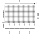
- Figure 7 is a diagram showing another example of PDCCH DMRS to which TD-OCC is applied.
- Figure 8 is a diagram showing an example of a PDCCH DMRS to which FD-OCC and TD-OCC are applied.
- Figure 9 is a diagram showing another example of PDCCH DMRS to which FD-OCC and TD-OCC are applied.
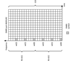
- Figure 10 is a diagram showing an example of a PDCCH DMRS to which FDM is applied.
- Figure 11 is a diagram showing another example of a PDCCH DMRS to which FDM is applied.
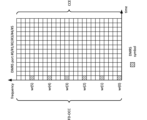
- Figure 12 is a diagram showing an example of a PDCCH DMRS to which TDM is applied.
- Figure 13 is a diagram showing another example of a PDCCH DMRS to which TDM is applied.
- a data channel e.g., PDSCH/PUSCH
- PDSCH DMRS (non-data multiplexing) with a symbol length of 13 symbols and 2 symbols as mapping pattern 1.
- PUSCH DMRS (non-data multiplexing) with a symbol length of 14 symbols and 2 symbols.
- Other reference signals (RS)/channels etc. are not taken into account.
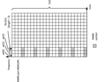
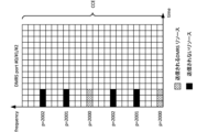
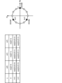
- Figure 1A shows an example of the number of UEs accommodated per slot/symbol for each channel.
- Figure 1A shows an example of the number of UEs accommodated per slot for each channel calculated based on the number of RBs.
- MCS modulation and coding scheme
- the number of UEs accommodated by PUSCH per slot in the case of MCS index 0, 10 RBs are required per UE, so the number of UEs accommodated is calculated to be 27. In addition, in the case of MCS index 5, 3 RBs are required per UE, so the number of UEs accommodated is calculated to be 91.
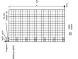
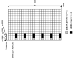
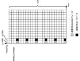
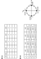
- Figure 1B shows an example of the number of UEs accommodated per cell for each channel.
- Figure 1B shows an example of the number of UEs accommodated per cell for each channel (the number of DCIs for PDCCH) calculated based on the TDD setting.
- a 1-symbol PDCCH can accommodate 392 DCIs (UL DCIs and DL DCIs), and a 2-symbol PDCCH can accommodate 784 DCIs (UL DCIs and DL DCIs).
- a 1-symbol PDCCH can accommodate 784 DCIs (UL DCIs and DL DCIs)
- a 2-symbol PDCCH can accommodate 1,568 DCIs (UL DCIs and DL DCIs).
- the number of UEs accommodated by the PUSCH per cell in the case of MCS index 0, 10 RBs are required per UE, so the number of UEs accommodated is calculated to be 216. In addition, in the case of MCS index 5, 3 RBs are required per UE, so the number of UEs accommodated is calculated to be 728.
- a control channel e.g., PDCCH/DCI
- the number of PDCCHs/DCIs per cell is at least about 400, which is considered to be sufficiently large.
- PDCCH/DCI can be transmitted so that it is spread across all PDCCH resources.
- the base station In actual transmission, due to overbooking of PDCCH, the base station cannot simultaneously transmit as many PDCCHs as the number calculated above. In other words, if candidate resources for PDCCHs between UEs overlap in the time domain, a situation occurs in which PDCCH cannot be transmitted.
- A/B and “at least one of A and B” may be interpreted as interchangeable. Also, in this disclosure, “A/B/C” may mean “at least one of A, B, and C.”
- Radio Resource Control RRC
- RRC parameters RRC parameters
- RRC messages higher layer parameters, fields, information elements (IEs), settings, etc.
- IEs information elements
- CE Medium Access Control
- update commands activation/deactivation commands, etc.
- the higher layer signaling may be, for example, any one of Radio Resource Control (RRC) signaling, Medium Access Control (MAC) signaling, broadcast information, other messages (e.g., messages from the core network such as positioning protocols (e.g., NR Positioning Protocol A (NRPPa)/LTE Positioning Protocol (LPP)) messages), or a combination of these.
- RRC Radio Resource Control
- MAC Medium Access Control
- LPP LTE Positioning Protocol
- the MAC signaling may use, for example, a MAC Control Element (MAC CE), a MAC Protocol Data Unit (PDU), etc.
- the broadcast information may be, for example, a Master Information Block (MIB), a System Information Block (SIB), Remaining Minimum System Information (RMSI), Other System Information (OSI), etc.
- MIB Master Information Block
- SIB System Information Block
- RMSI Remaining Minimum System Information
- OSI System Information
- the physical layer signaling may be, for example, Downlink Control Information (DCI), Uplink Control Information (UCI), etc.
- DCI Downlink Control Information
- UCI Uplink Control Information
- the UE may receive the PDCCH with more than one rank/layer.
- the frequency resources e.g., aggregation level
- the frequency resources e.g., aggregation level
- the frequency resources e.g., aggregation level
- Each embodiment of the present disclosure may be applied only when certain parameters/fields are configured using higher layer signaling (e.g., RRC signaling/MAC CE).
- higher layer signaling e.g., RRC signaling/MAC CE.
- the number of receiving layers/ranks of the PDCCH may be configured for the UE using higher layer signaling, and the UE may receive DCI using the configured number of layers/ranks.
- the maximum number of layers/maximum ranks for receiving PDCCH may be set for the UE using higher layer signaling, and the UE may receive DCI using a number of layers/ranks equal to or less than the set maximum number of layers/maximum ranks.
- the configuration via the higher layer signaling may be performed, for example, per search space/per CORESET/per BWP/per CC/per band/per UE.
- Each embodiment of the present disclosure may be applied only when specific UE capability information (support for a specific UE capability) is reported.
- the UE capability information may be reported, for example, per band, per band combination (BC), per band within a BC, or per band within a BC and per CC (per CC per band in BC).
- Each embodiment of the present disclosure may be applied to a specific search space (SS)/SS set.
- the specific SS/SS set may be, for example, a UE-specific search space (USS) or a specific common search space (CSS, for example, type 3 CSS).
- USS UE-specific search space
- CSS common search space
- a configuration can be created that excludes CSSs for multiple UEs of types 0/0A/1/2.
- Figure 12 is a diagram showing an example of PDCCH DMRS to which TDM is applied.
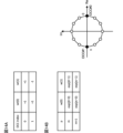
- FIGS. 16A and 16B are diagrams showing other examples of OCC sequences.
- an example of an OCC using a Walsh matrix with a sequence length of 4 is shown
- an example of an OCC using a cyclic shift with a sequence length of 4 is shown.
- the OCC with a sequence length of 4 shown in FIG. 16A and 16B may be applied to the DMRS of a PDCCH.
- FIG. 17 is a diagram showing another example of an OCC sequence.
- an example of an OCC using a cyclic shift with a sequence length of 6 is shown.
- the OCC with a sequence length of 6 shown in FIG. 17 may be applied to the DMRS of a PDCCH.
- the third embodiment relates to the transmission power/power density of the PDCCH/DMRS.
- the transmission power for each symbol/RE is desirable for the transmission power for each symbol/RE to be constant.
- the power density e.g., Energy Per Resource Element (EPRE)
- EPRE Energy Per Resource Element
- the transmission power when some DMRS are not transmitted will be explained using FIG. 11 as an example again.
- the UE may be configured to not transmit some PDCCH/DMRS (resources/REs).
- the UE may be configured for PDCCH DMRS using the above FDM/TDM.
- the transmission power may be constant for time resources (e.g., symbols) of the DMRS/PDCCH when some DMRS/PDCCH (resources/REs) are not transmitted and for time resources (e.g., symbols) of the DMRS/PDCCH other than those time resources.
- the UE may assume that the transmission power of a DMRS/PDCCH time resource (e.g., symbol) when some DMRS/PDCCH (resources/REs) are not transmitted is determined based on the transmission power of the DMRS/PDCCH time resource (e.g., symbol) other than the time resource.
- a DMRS/PDCCH time resource e.g., symbol
- the power density (e.g., Effective Isotropic Radiated Power (EIRP)) of the PDCCH/DMRS in the symbol may be a specific number (e.g., N all /(N all -P)) times the power density of other symbols.
- EIRP Effective Isotropic Radiated Power
- the own UE may assume that the transmission power of resources excluding the power of the DMRS (resources/REs) for other UEs in a certain symbol is smaller than the transmission power of a symbol in which no DMRS is transmitted.
- the base station may control the transmission power of a symbol transmitting DMRS for multiple UEs to be equal to the transmission power of a symbol in which no DMRS is transmitted.
- FIG. 19 is a diagram showing an example of the transmission power of the PDCCH/DMRS according to the third embodiment.
- the example shown in FIG. 19 shows resources of 1 slot (14 symbols) and 1 CCE.
- the UE assumes that the transmission power/power density within 1 CCE in each symbol (symbols #0 to #2) in which some DMRS is not transmitted, and the transmission power/power density within 1 CCE in each other symbol are constant.
- the fourth embodiment relates to a precoder applied to a PDCCH.
- the UE may be configured/instructed as to whether or not the DMRS of the PDCCH is to be transmitted.
- the configuration/instruction may be performed, for example, using higher layer signaling (RRC/MAC CE)/DCI (e.g., previously received DCI).
- RRC/MAC CE higher layer signaling
- DCI previously received DCI
- the UE may not be notified of the precoder to be applied to the PDCCH.
- the UE may assume that the precoder to be applied to the PDCCH will not be notified.
- the precoder to be applied to the PDCCH does not need to be notified.
- the UE may assume/determine that the PDCCH and the DMRS of the PDCCH are transmitted using the same precoder.
- the UE may be notified of the precoder to be applied to the PDCCH.
- the UE may assume that the precoder to be applied to the PDCCH is notified.
- the precoder to be applied to the PDCCH may be notified.
- the UE may receive a cell-common/UE-common RS (e.g., CRS/CSI-RS/TRS) and be notified of the precoder (phase difference) of the PDCCH compared to the RS.
- a cell-common/UE-common RS e.g., CRS/CSI-RS/TRS
- the precoder may be notified, for example, using higher layer signaling (RRC/MAC CE)/DCI (e.g., previously received DCI).
- RRC/MAC CE higher layer signaling
- DCI previously received DCI
- the precoder to be applied to the PDCCH does not need to be notified.
- the UE may detect DCI from a specific precoder candidate using blind detection.
- the specific precoder candidate may be specified in advance in the specifications, or may be configured/instructed to the UE using higher layer signaling (RRC/MAC CE)/DCI.
- the network/base station may determine the precoder to be applied to the PDCCH using Channel Reciprocity based on UL reception from the UE (e.g., SRS/PUSCH/PUCCH/PUSCH DMRS/PUCCH DMRS).
- Channel Reciprocity based on UL reception from the UE (e.g., SRS/PUSCH/PUCCH/PUSCH DMRS/PUCCH DMRS).
- the network/base station may also decide to use a precoder determined based on CSI feedback for the PDSCH for the PDCCH.
- the UE may assume that in the case of two ports/layers, linear polarization (e.g., vertical and horizontal polarization) is used for PDCCH transmission. Also, for example, the UE may assume that in the case of two ports/layers, circular polarization (e.g., right hand circular polarization (RHCP) and left hand circular polarization (LHCP)) is used for PDCCH transmission.
- linear polarization e.g., vertical and horizontal polarization
- circular polarization e.g., right hand circular polarization (RHCP) and left hand circular polarization (LHCP)
- the UE may assume that for 3 or 4 ports/layers, a combination of linear and circular polarization is used for PDCCH transmission.
- the UE may perform a report (e.g., CSI feedback) to determine the precoder of the PDCCH.
- the UE may receive a specific DL reference signal (e.g., CSI-RS/TRS) and generate/determine the report.
- the report may be performed, for example, using UCI/MAC CE (PUSCH).
- the report may be made only when PDCCH reception is configured using a number of layers/ports greater than (or equal to) a specific number of layers/ports (e.g., 2, 4).
- the report may be made only when PDCCH reception is configured using a number of layers/ports less than (or equal to) a specific number of layers/ports (e.g., 2, 4).
- the UE may receive an instruction (precoder instruction) from the network/base station to determine the precoder for the PDCCH.
- the instruction may be given, for example, using DCI/MAC CE.
- the instruction may be sent based on a report from the UE.
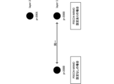
- the fifth embodiment relates to operation using multiple TRPs.
- a PDCCH using multiple layers/ports may be configured for the UE.
- Each PDCCH port/layer may correspond to a (different/same) TCI state.
- the correspondence of the TCI state may be set/indicated using higher layer signaling (RRC/MAC CE)/DCI.
- TRPs may be associated with one PDCCH port/layer.
- the number of paths can be increased, thereby improving the expected performance rank and improving performance.
- the above-mentioned embodiments may be applied when the UE configures/activates/triggers specific information related to the above-mentioned embodiments (or performs the operations of the above-mentioned embodiments) by higher layer signaling/physical layer signaling.
- the specific information may be information indicating that reception of PDCCH using multi-layer/port/rank is enabled, any RRC parameters for a specific release (e.g., Rel. 18/19), etc.
- the UE may, for example, apply Rel. 15/16 operations.
- Appendix A With respect to one embodiment of the present disclosure, the following invention is noted.
- Appendix A-1 A terminal having a receiving unit that receives a setting regarding the number or maximum number of layers to be used for receiving a physical downlink control channel (PDCCH) using multiple layers, and a control unit that controls reception of the PDCCH using the multiple layers based on the setting.
- Appendix A-2 The terminal according to appendix A-1, wherein the control unit determines that a layer having a smaller or larger number among the plurality of layers has a higher priority.
- a terminal having a receiver that receives a demodulation reference signal (DMRS) of a physical downlink control channel (PDCCH) using multiple layers, the DMRS being mapped using a frequency domain orthogonal cover code (FD-OCC), a time domain OCC (TD-OCC), a frequency domain and time domain OCC, frequency division multiplexing (FDM), or time division multiplexing (TDM), and a control unit that controls reception of the PDCCH based on the DMRS.
- DMRS demodulation reference signal
- PDCCH physical downlink control channel
- FD-OCC frequency domain orthogonal cover code
- TD-OCC time domain OCC
- FDM frequency division multiplexing
- TDM time division multiplexing
- Appendix B-2 The terminal according to Supplementary Note B-1, wherein the control unit determines that an antenna port number for a first layer among the plurality of layers and an antenna port number corresponding to a PDCCH that does not use the plurality of layers are identical.
- Appendix B-3 The terminal described in Appendix B-1 or Appendix B-2, wherein the receiving unit receives a first setting regarding the number of the multiple layers and a second setting regarding antenna port numbers corresponding to the PDCCH and the DMRS, and the control unit detects downlink control information transmitted on the PDCCH based on the first setting and the second setting.
- Appendix B-4 A terminal described in any one of Supplementary Notes B-1 to B-3, in which, when a DMRS symbol corresponding to a specific port is not transmitted in a symbol in which the DMRS using the FDM or the DMRS using the TDM is transmitted, the control unit assumes that the power density in a time resource of the DMRS symbol is equal to the power density in a time resource other than the time resource.
- Wired communication system A configuration of a wireless communication system according to an embodiment of the present disclosure will be described below.
- communication is performed using any one of the wireless communication methods according to the above embodiments of the present disclosure or a combination of these.
- FIG. 20 is a diagram showing an example of a schematic configuration of a wireless communication system according to an embodiment.
- the wireless communication system 1 (which may simply be referred to as system 1) may be a system that realizes communication using Long Term Evolution (LTE) specified by the Third Generation Partnership Project (3GPP), 5th generation mobile communication system New Radio (5G NR), or the like.
- LTE Long Term Evolution
- 3GPP Third Generation Partnership Project
- 5G NR 5th generation mobile communication system New Radio
- the wireless communication system 1 may also support dual connectivity between multiple Radio Access Technologies (RATs) (Multi-RAT Dual Connectivity (MR-DC)).
- MR-DC may include dual connectivity between LTE (Evolved Universal Terrestrial Radio Access (E-UTRA)) and NR (E-UTRA-NR Dual Connectivity (EN-DC)), dual connectivity between NR and LTE (NR-E-UTRA Dual Connectivity (NE-DC)), etc.
- RATs Radio Access Technologies
- MR-DC may include dual connectivity between LTE (Evolved Universal Terrestrial Radio Access (E-UTRA)) and NR (E-UTRA-NR Dual Connectivity (EN-DC)), dual connectivity between NR and LTE (NR-E-UTRA Dual Connectivity (NE-DC)), etc.
- E-UTRA Evolved Universal Terrestrial Radio Access
- EN-DC E-UTRA-NR Dual Connectivity
- NE-DC NR-E-UTRA Dual Connectivity
- the LTE (E-UTRA) base station (eNB) is the master node (MN), and the NR base station (gNB) is the secondary node (SN).
- the NR base station (gNB) is the MN, and the LTE (E-UTRA) base station (eNB) is the SN.
- the wireless communication system 1 may support dual connectivity between multiple base stations within the same RAT (e.g., dual connectivity in which both the MN and SN are NR base stations (gNBs) (NR-NR Dual Connectivity (NN-DC))).
- dual connectivity in which both the MN and SN are NR base stations (gNBs) (NR-NR Dual Connectivity (NN-DC))).
- gNBs NR base stations
- N-DC Dual Connectivity
- the wireless communication system 1 may include a base station 11 that forms a macrocell C1 with a relatively wide coverage, and base stations 12 (12a-12c) that are arranged within the macrocell C1 and form a small cell C2 that is narrower than the macrocell C1.
- a user terminal 20 may be located within at least one of the cells. The arrangement and number of each cell and user terminal 20 are not limited to the embodiment shown in the figure. Hereinafter, when there is no need to distinguish between the base stations 11 and 12, they will be collectively referred to as base station 10.
- the user terminal 20 may be connected to at least one of the multiple base stations 10.
- the user terminal 20 may utilize at least one of carrier aggregation (CA) using multiple component carriers (CC) and dual connectivity (DC).
- CA carrier aggregation
- CC component carriers
- DC dual connectivity
- Each CC may be included in at least one of a first frequency band (Frequency Range 1 (FR1)) and a second frequency band (Frequency Range 2 (FR2)).
- Macro cell C1 may be included in FR1
- small cell C2 may be included in FR2.
- FR1 may be a frequency band below 6 GHz (sub-6 GHz)
- FR2 may be a frequency band above 24 GHz (above-24 GHz). Note that the frequency bands and definitions of FR1 and FR2 are not limited to these, and for example, FR1 may correspond to a higher frequency band than FR2.
- the user terminal 20 may communicate using at least one of Time Division Duplex (TDD) and Frequency Division Duplex (FDD) in each CC.
- TDD Time Division Duplex
- FDD Frequency Division Duplex
- the multiple base stations 10 may be connected by wire (e.g., optical fiber conforming to the Common Public Radio Interface (CPRI), X2 interface, etc.) or wirelessly (e.g., NR communication).
- wire e.g., optical fiber conforming to the Common Public Radio Interface (CPRI), X2 interface, etc.
- NR communication e.g., NR communication
- base station 11 which corresponds to the upper station
- IAB Integrated Access Backhaul
- base station 12 which corresponds to a relay station
- the base station 10 may be connected to the core network 30 via another base station 10 or directly.
- the core network 30 may include, for example, at least one of an Evolved Packet Core (EPC), a 5G Core Network (5GCN), a Next Generation Core (NGC), etc.
- EPC Evolved Packet Core
- 5GCN 5G Core Network
- NGC Next Generation Core
- the core network 30 may include network functions (Network Functions (NF)) such as, for example, a User Plane Function (UPF), an Access and Mobility management Function (AMF), a Session Management Function (SMF), a Unified Data Management (UDM), an Application Function (AF), a Data Network (DN), a Location Management Function (LMF), and Operation, Administration and Maintenance (Management) (OAM).
- NF Network Functions
- UPF User Plane Function
- AMF Access and Mobility management Function
- SMF Session Management Function
- UDM Unified Data Management
- AF Application Function
- DN Data Network
- LMF Location Management Function
- OAM Operation, Administration and Maintenance
- the user terminal 20 may be a terminal that supports at least one of the communication methods such as LTE, LTE-A, and 5G.
- a wireless access method based on Orthogonal Frequency Division Multiplexing may be used.
- OFDM Orthogonal Frequency Division Multiplexing
- CP-OFDM Cyclic Prefix OFDM
- DFT-s-OFDM Discrete Fourier Transform Spread OFDM
- OFDMA Orthogonal Frequency Division Multiple Access
- SC-FDMA Single Carrier Frequency Division Multiple Access
- the radio access method may also be called a waveform.
- other radio access methods e.g., other single-carrier transmission methods, other multi-carrier transmission methods
- a downlink shared channel (Physical Downlink Shared Channel (PDSCH)) shared by each user terminal 20, a broadcast channel (Physical Broadcast Channel (PBCH)), a downlink control channel (Physical Downlink Control Channel (PDCCH)), etc. may be used as the downlink channel.
- PDSCH Physical Downlink Shared Channel
- PBCH Physical Broadcast Channel
- PDCCH Physical Downlink Control Channel
- an uplink shared channel (Physical Uplink Shared Channel (PUSCH)) shared by each user terminal 20, an uplink control channel (Physical Uplink Control Channel (PUCCH)), a random access channel (Physical Random Access Channel (PRACH)), etc. may be used as an uplink channel.
- PUSCH Physical Uplink Shared Channel
- PUCCH Physical Uplink Control Channel
- PRACH Physical Random Access Channel
- SIB System Information Block
- PDSCH User data, upper layer control information, System Information Block (SIB), etc.
- SIB System Information Block
- PUSCH User data, upper layer control information, etc.
- MIB Master Information Block
- PBCH Physical Broadcast Channel
- Lower layer control information may be transmitted by the PDCCH.
- the lower layer control information may include, for example, downlink control information (Downlink Control Information (DCI)) including scheduling information for at least one of the PDSCH and the PUSCH.
- DCI Downlink Control Information
- the DCI for scheduling the PDSCH may be called a DL assignment or DL DCI
- the DCI for scheduling the PUSCH may be called a UL grant or UL DCI.
- the PDSCH may be interpreted as DL data
- the PUSCH may be interpreted as UL data.
- a control resource set (COntrol REsource SET (CORESET)) and a search space may be used to detect the PDCCH.
- the CORESET corresponds to the resources to search for DCI.
- the search space corresponds to the search region and search method of PDCCH candidates.
- One CORESET may be associated with one or multiple search spaces. The UE may monitor the CORESET associated with a certain search space based on the search space configuration.
- a search space may correspond to PDCCH candidates corresponding to one or more aggregation levels.
- One or more search spaces may be referred to as a search space set. Note that the terms “search space,” “search space set,” “search space setting,” “search space set setting,” “CORESET,” “CORESET setting,” etc. in this disclosure may be read as interchangeable.
- the PUCCH may transmit uplink control information (UCI) including at least one of channel state information (CSI), delivery confirmation information (which may be called, for example, Hybrid Automatic Repeat reQuest ACKnowledgement (HARQ-ACK), ACK/NACK, etc.), and a scheduling request (SR).
- UCI uplink control information
- CSI channel state information
- HARQ-ACK Hybrid Automatic Repeat reQuest ACKnowledgement
- ACK/NACK ACK/NACK
- SR scheduling request
- the PRACH may transmit a random access preamble for establishing a connection with a cell.
- downlink, uplink, etc. may be expressed without adding "link.”
- various channels may be expressed without adding "Physical” to the beginning.
- a synchronization signal (SS), a downlink reference signal (DL-RS), etc. may be transmitted.
- a cell-specific reference signal (CRS), a channel state information reference signal (CSI-RS), a demodulation reference signal (DMRS), a positioning reference signal (PRS), a phase tracking reference signal (PTRS), etc. may be transmitted.
- the synchronization signal may be, for example, at least one of a Primary Synchronization Signal (PSS) and a Secondary Synchronization Signal (SSS).
- a signal block including an SS (PSS, SSS) and a PBCH (and a DMRS for PBCH) may be called an SS/PBCH block, an SS Block (SSB), etc.
- SS, SSB, etc. may also be called reference signals.
- a measurement reference signal Sounding Reference Signal (SRS)
- a demodulation reference signal DMRS
- UL-RS uplink reference signal
- DMRS may also be called a user equipment-specific reference signal (UE-specific Reference Signal).
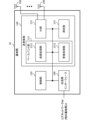
- the base station 21 is a diagram showing an example of a configuration of a base station according to an embodiment.
- the base station 10 includes a control unit 110, a transceiver unit 120, a transceiver antenna 130, and a transmission line interface 140. Note that one or more of each of the control unit 110, the transceiver unit 120, the transceiver antenna 130, and the transmission line interface 140 may be provided.
- this example mainly shows the functional blocks of the characteristic parts of this embodiment, and the base station 10 may also be assumed to have other functional blocks necessary for wireless communication. Some of the processing of each part described below may be omitted.
- the control unit 110 controls the entire base station 10.
- the control unit 110 can be configured from a controller, a control circuit, etc., which are described based on a common understanding in the technical field to which this disclosure pertains.
- the control unit 110 may control signal generation, scheduling (e.g., resource allocation, mapping), etc.
- the control unit 110 may control transmission and reception using the transceiver unit 120, the transceiver antenna 130, and the transmission path interface 140, measurement, etc.
- the control unit 110 may generate data, control information, sequences, etc. to be transmitted as signals, and transfer them to the transceiver unit 120.
- the control unit 110 may perform call processing of communication channels (setting, release, etc.), status management of the base station 10, management of radio resources, etc.
- the transceiver unit 120 may include a baseband unit 121, a radio frequency (RF) unit 122, and a measurement unit 123.
- the baseband unit 121 may include a transmission processing unit 1211 and a reception processing unit 1212.
- the transceiver unit 120 may be composed of a transmitter/receiver, an RF circuit, a baseband circuit, a filter, a phase shifter, a measurement circuit, a transceiver circuit, etc., which are described based on a common understanding in the technical field to which the present disclosure relates.
- the transceiver unit 120 may be configured as an integrated transceiver unit, or may be composed of a transmission unit and a reception unit.
- the transmission unit may be composed of a transmission processing unit 1211 and an RF unit 122.
- the reception unit may be composed of a reception processing unit 1212, an RF unit 122, and a measurement unit 123.
- the transmitting/receiving antenna 130 can be configured as an antenna described based on common understanding in the technical field to which this disclosure pertains, such as an array antenna.
- the transceiver 120 may transmit the above-mentioned downlink channel, synchronization signal, downlink reference signal, etc.
- the transceiver 120 may receive the above-mentioned uplink channel, uplink reference signal, etc.
- the transceiver 120 may perform Packet Data Convergence Protocol (PDCP) layer processing, Radio Link Control (RLC) layer processing (e.g., RLC retransmission control), Medium Access Control (MAC) layer processing (e.g., HARQ retransmission control), etc. on data and control information obtained from the control unit 110 to generate a bit string to be transmitted.
- PDCP Packet Data Convergence Protocol
- RLC Radio Link Control
- MAC Medium Access Control
- HARQ retransmission control HARQ retransmission control
- the transceiver unit 120 may perform transmission processing such as channel coding (which may include error correction coding), modulation, mapping, filtering, Discrete Fourier Transform (DFT) processing (if necessary), Inverse Fast Fourier Transform (IFFT) processing, precoding, and digital-to-analog conversion on the bit string to be transmitted, and output a baseband signal.
- transmission processing such as channel coding (which may include error correction coding), modulation, mapping, filtering, Discrete Fourier Transform (DFT) processing (if necessary), Inverse Fast Fourier Transform (IFFT) processing, precoding, and digital-to-analog conversion on the bit string to be transmitted, and output a baseband signal.
- channel coding which may include error correction coding
- DFT Discrete Fourier Transform
- IFFT Inverse Fast Fourier Transform
- the transceiver unit 120 may perform amplification, filtering, demodulation to a baseband signal, etc. on the radio frequency band signal received by the transceiver antenna 130.
- the transceiver 120 may perform measurements on the received signal.
- the measurement unit 123 may perform Radio Resource Management (RRM) measurements, Channel State Information (CSI) measurements, etc. based on the received signal.
- the measurement unit 123 may measure received power (e.g., Reference Signal Received Power (RSRP)), received quality (e.g., Reference Signal Received Quality (RSRQ), Signal to Interference plus Noise Ratio (SINR), Signal to Noise Ratio (SNR)), signal strength (e.g., Received Signal Strength Indicator (RSSI)), propagation path information (e.g., CSI), etc.
- RSRP Reference Signal Received Power
- RSSI Received Signal Strength Indicator
- the measurement results may be output to the control unit 110.
- the transmission path interface 140 may transmit and receive signals (backhaul signaling) between devices included in the core network 30 (e.g., network nodes providing NF), other base stations 10, etc., and may acquire and transmit user data (user plane data), control plane data, etc. for the user terminal 20.
- devices included in the core network 30 e.g., network nodes providing NF
- other base stations 10, etc. may acquire and transmit user data (user plane data), control plane data, etc. for the user terminal 20.
- the transmitting unit and receiving unit of the base station 10 in this disclosure may be configured by at least one of the transmitting/receiving unit 120, the transmitting/receiving antenna 130, and the transmission path interface 140.
- the transceiver 120 may transmit a setting regarding the number or maximum number of layers to be used for receiving a physical downlink control channel (PDCCH) using multiple layers.
- the control unit 110 may use the setting to control the transmission of the PDCCH using the multiple layers (first embodiment).
- the transceiver unit 120 may transmit a demodulation reference signal (DMRS) for a physical downlink control channel (PDCCH) using multiple layers, the DMRS being mapped using a frequency domain orthogonal cover code (FD-OCC), a time domain OCC (TD-OCC), a frequency domain and a time domain OCC, frequency division multiplexing (FDM), or time division multiplexing (TDM).
- DMRS demodulation reference signal
- PDCCH physical downlink control channel
- FD-OCC frequency domain orthogonal cover code
- TD-OCC time domain OCC
- FDM frequency division multiplexing
- TDM time division multiplexing
- the control unit 110 may use the DMRS to instruct the reception processing of the PDCCH (second embodiment).
- the user terminal 22 is a diagram showing an example of the configuration of a user terminal according to an embodiment.
- the user terminal 20 includes a control unit 210, a transmitting/receiving unit 220, and a transmitting/receiving antenna 230.
- the control unit 210, the transmitting/receiving unit 220, and the transmitting/receiving antenna 230 may each include one or more.
- this example mainly shows the functional blocks of the characteristic parts of this embodiment, and the user terminal 20 may also be assumed to have other functional blocks necessary for wireless communication. Some of the processing of each part described below may be omitted.
- the control unit 210 controls the entire user terminal 20.
- the control unit 210 can be configured from a controller, a control circuit, etc., which are described based on a common understanding in the technical field to which this disclosure pertains.
- the control unit 210 may control signal generation, mapping, etc.
- the control unit 210 may control transmission and reception using the transceiver unit 220 and the transceiver antenna 230, measurement, etc.
- the control unit 210 may generate data, control information, sequences, etc. to be transmitted as signals, and transfer them to the transceiver unit 220.
- the transceiver unit 220 may include a baseband unit 221, an RF unit 222, and a measurement unit 223.
- the baseband unit 221 may include a transmission processing unit 2211 and a reception processing unit 2212.
- the transceiver unit 220 may be composed of a transmitter/receiver, an RF circuit, a baseband circuit, a filter, a phase shifter, a measurement circuit, a transceiver circuit, etc., which are described based on a common understanding in the technical field to which the present disclosure relates.
- the transceiver unit 220 may be configured as an integrated transceiver unit, or may be composed of a transmission unit and a reception unit.
- the transmission unit may be composed of a transmission processing unit 2211 and an RF unit 222.
- the reception unit may be composed of a reception processing unit 2212, an RF unit 222, and a measurement unit 223.
- the transmitting/receiving antenna 230 can be configured as an antenna described based on common understanding in the technical field to which this disclosure pertains, such as an array antenna.
- the transceiver 220 may receive the above-mentioned downlink channel, synchronization signal, downlink reference signal, etc.
- the transceiver 220 may transmit the above-mentioned uplink channel, uplink reference signal, etc.
- the transceiver unit 220 may form at least one of the transmit beam and the receive beam using digital beamforming (e.g., precoding), analog beamforming (e.g., phase rotation), etc.
- digital beamforming e.g., precoding
- analog beamforming e.g., phase rotation
- the transceiver 220 may perform PDCP layer processing, RLC layer processing (e.g., RLC retransmission control), MAC layer processing (e.g., HARQ retransmission control), etc. on the data and control information acquired from the controller 210, and generate a bit string to be transmitted.
- RLC layer processing e.g., RLC retransmission control
- MAC layer processing e.g., HARQ retransmission control
- the transceiver 220 may perform transmission processing such as channel coding (which may include error correction coding), modulation, mapping, filtering, DFT processing (if necessary), IFFT processing, precoding, and digital-to-analog conversion on the bit string to be transmitted, and output a baseband signal.
- transmission processing such as channel coding (which may include error correction coding), modulation, mapping, filtering, DFT processing (if necessary), IFFT processing, precoding, and digital-to-analog conversion on the bit string to be transmitted, and output a baseband signal.
- Whether or not to apply DFT processing may be based on the settings of transform precoding.
- the transceiver unit 220 transmission processing unit 2211
- the transceiver unit 220 may perform DFT processing as the above-mentioned transmission processing in order to transmit the channel using a DFT-s-OFDM waveform, and when transform precoding is not enabled, it is not necessary to perform DFT processing as the above-mentioned transmission processing.
- the transceiver unit 220 may perform modulation, filtering, amplification, etc., on the baseband signal to a radio frequency band, and transmit the radio frequency band signal via the transceiver antenna 230.
- the transceiver unit 220 may perform amplification, filtering, demodulation to a baseband signal, etc. on the radio frequency band signal received by the transceiver antenna 230.
- the transceiver 220 may perform measurements on the received signal. For example, the measurement unit 223 may perform RRM measurements, CSI measurements, etc. based on the received signal.
- the measurement unit 223 may measure received power (e.g., RSRP), received quality (e.g., RSRQ, SINR, SNR), signal strength (e.g., RSSI), propagation path information (e.g., CSI), etc.
- the measurement results may be output to the control unit 210.
- the transceiver 220 may receive a setting regarding the number or maximum number of layers to be used for receiving a physical downlink control channel (PDCCH) using multiple layers.
- the control unit 210 may control the reception of the PDCCH using the multiple layers based on the setting (first embodiment).
- the control unit 210 may determine that a layer with a lower or higher number among the multiple layers has a higher priority (first embodiment).
- the transceiver unit 220 may receive information regarding a precoder to be applied to the PDCCH. If the demodulation reference signal is transmitted, the control unit 210 may assume that the PDCCH and the demodulation reference signal are transmitted using the same precoder (fourth embodiment).
- the multiple layers may correspond to different transmission configuration indication (TCI) states (fifth embodiment).
- TCI transmission configuration indication
- the transceiver unit 220 may receive a demodulation reference signal (DMRS) of a physical downlink control channel (PDCCH) using multiple layers, the DMRS being mapped using a frequency domain orthogonal cover code (FD-OCC), a time domain OCC (TD-OCC), a frequency domain and a time domain OCC, frequency division multiplexing (FDM), or time division multiplexing (TDM).
- DMRS demodulation reference signal
- PDCCH physical downlink control channel
- FD-OCC frequency domain orthogonal cover code
- TD-OCC time domain OCC
- FDM frequency division multiplexing
- TDM time division multiplexing
- the control unit 210 may control reception of the PDCCH based on the DMRS (second embodiment).
- the control unit 210 may determine that the antenna port number for the first layer of the multiple layers is the same as the antenna port number corresponding to a PDCCH that does not use the multiple layers (second embodiment).
- the transceiver 220 may receive a first setting related to the number of the layers and a second setting related to the antenna port numbers corresponding to the PDCCH and the DMRS.
- the controller 210 may detect downlink control information transmitted on the PDCCH based on the first setting and the second setting (second embodiment).
- control unit 210 may assume that the power density in the time resource of the DMRS symbol is equal to the power density in a time resource other than the time resource (third embodiment).
- each functional block may be realized using one device that is physically or logically coupled, or may be realized using two or more devices that are physically or logically separated and directly or indirectly connected (for example, using wires, wirelessly, etc.).
- the functional blocks may be realized by combining the one device or the multiple devices with software.
- the functions include, but are not limited to, judgement, determination, judgment, calculation, computation, processing, derivation, investigation, search, confirmation, reception, transmission, output, access, resolution, selection, selection, establishment, comparison, assumption, expectation, deeming, broadcasting, notifying, communicating, forwarding, configuring, reconfiguring, allocating, mapping, and assignment.
- a functional block (component) that performs the transmission function may be called a transmitting unit, a transmitter, and the like. In either case, as mentioned above, there are no particular limitations on the method of realization.
- a base station, a user terminal, etc. in one embodiment of the present disclosure may function as a computer that performs processing of the wireless communication method of the present disclosure.
- FIG. 23 is a diagram showing an example of the hardware configuration of a base station and a user terminal according to one embodiment.
- the above-mentioned base station 10 and user terminal 20 may be physically configured as a computer device including a processor 1001, a memory 1002, a storage 1003, a communication device 1004, an input device 1005, an output device 1006, a bus 1007, etc.
- the terms apparatus, circuit, device, section, unit, etc. may be interpreted as interchangeable.
- the hardware configurations of the base station 10 and the user terminal 20 may be configured to include one or more of the devices shown in the figures, or may be configured to exclude some of the devices.
- processor 1001 may be implemented by one or more chips.
- the functions of the base station 10 and the user terminal 20 are realized, for example, by loading specific software (programs) onto hardware such as the processor 1001 and memory 1002, causing the processor 1001 to perform calculations, control communications via the communication device 1004, and control at least one of the reading and writing of data in the memory 1002 and storage 1003.
- the processor 1001 for example, runs an operating system to control the entire computer.
- the processor 1001 may be configured as a central processing unit (CPU) including an interface with peripheral devices, a control device, an arithmetic unit, registers, etc.
- CPU central processing unit
- control unit 110 210
- transmission/reception unit 120 220
- etc. may be realized by the processor 1001.
- the processor 1001 also reads out programs (program codes), software modules, data, etc. from at least one of the storage 1003 and the communication device 1004 into the memory 1002, and executes various processes according to these.
- the programs used are those that cause a computer to execute at least some of the operations described in the above embodiments.
- the control unit 110 (210) may be realized by a control program stored in the memory 1002 and running on the processor 1001, and similar implementations may be made for other functional blocks.
- Memory 1002 is a computer-readable recording medium and may be composed of at least one of, for example, Read Only Memory (ROM), Erasable Programmable ROM (EPROM), Electrically EPROM (EEPROM), Random Access Memory (RAM), and other suitable storage media. Memory 1002 may also be called a register, cache, main memory, etc. Memory 1002 can store executable programs (program codes), software modules, etc. for implementing a wireless communication method according to one embodiment of the present disclosure.
- ROM Read Only Memory
- EPROM Erasable Programmable ROM
- EEPROM Electrically EPROM
- RAM Random Access Memory
- Memory 1002 may also be called a register, cache, main memory, etc.
- Memory 1002 can store executable programs (program codes), software modules, etc. for implementing a wireless communication method according to one embodiment of the present disclosure.
- Storage 1003 is a computer-readable recording medium and may be composed of at least one of a flexible disk, a floppy disk, a magneto-optical disk (e.g., a compact disk (Compact Disc ROM (CD-ROM)), a digital versatile disk, a Blu-ray disk), a removable disk, a hard disk drive, a smart card, a flash memory device (e.g., a card, a stick, a key drive), a magnetic stripe, a database, a server, or other suitable storage medium.
- Storage 1003 may also be referred to as an auxiliary storage device.
- the communication device 1004 is hardware (transmitting/receiving device) for communicating between computers via at least one of a wired network and a wireless network, and is also called, for example, a network device, a network controller, a network card, a communication module, etc.
- the communication device 1004 may be configured to include a high-frequency switch, a duplexer, a filter, a frequency synthesizer, etc. to realize at least one of, for example, Frequency Division Duplex (FDD) and Time Division Duplex (TDD).
- FDD Frequency Division Duplex
- TDD Time Division Duplex
- the above-mentioned transmitting/receiving unit 120 (220), transmitting/receiving antenna 130 (230), etc. may be realized by the communication device 1004.
- the transmitting/receiving unit 120 (220) may be implemented as a transmitting unit 120a (220a) and a receiving unit 120b (220b) that are physically or logically separated.
- the input device 1005 is an input device (e.g., a keyboard, a mouse, a microphone, a switch, a button, a sensor, etc.) that accepts input from the outside.
- the output device 1006 is an output device (e.g., a display, a speaker, a Light Emitting Diode (LED) lamp, etc.) that outputs to the outside.
- the input device 1005 and the output device 1006 may be integrated into one structure (e.g., a touch panel).
- each device such as the processor 1001 and memory 1002 is connected by a bus 1007 for communicating information.
- the bus 1007 may be configured using a single bus, or may be configured using different buses between each device.
- the base station 10 and the user terminal 20 may be configured to include hardware such as a microprocessor, a digital signal processor (DSP), an application specific integrated circuit (ASIC), a programmable logic device (PLD), or a field programmable gate array (FPGA), and some or all of the functional blocks may be realized using the hardware.
- the processor 1001 may be implemented using at least one of these pieces of hardware.
- a channel, a symbol, and a signal may be read as mutually interchangeable.
- a signal may also be a message.
- a reference signal may be abbreviated as RS, and may be called a pilot, a pilot signal, or the like depending on the applied standard.
- a component carrier may also be called a cell, a frequency carrier, a carrier frequency, or the like.
- a radio frame may be composed of one or more periods (frames) in the time domain.
- Each of the one or more periods (frames) constituting a radio frame may be called a subframe.
- a subframe may be composed of one or more slots in the time domain.
- a subframe may have a fixed time length (e.g., 1 ms) that is independent of numerology.
- the numerology may be a communication parameter that is applied to at least one of the transmission and reception of a signal or channel.
- the numerology may indicate, for example, at least one of the following: SubCarrier Spacing (SCS), bandwidth, symbol length, cyclic prefix length, Transmission Time Interval (TTI), number of symbols per TTI, radio frame configuration, a specific filtering process performed by the transceiver in the frequency domain, a specific windowing process performed by the transceiver in the time domain, etc.
- SCS SubCarrier Spacing
- TTI Transmission Time Interval
- radio frame configuration a specific filtering process performed by the transceiver in the frequency domain
- a specific windowing process performed by the transceiver in the time domain etc.
- a slot may consist of one or more symbols in the time domain (such as Orthogonal Frequency Division Multiplexing (OFDM) symbols, Single Carrier Frequency Division Multiple Access (SC-FDMA) symbols, etc.).
- OFDM Orthogonal Frequency Division Multiplexing
- SC-FDMA Single Carrier Frequency Division Multiple Access
- a slot may also be a time unit based on numerology.
- a slot may include multiple minislots. Each minislot may consist of one or multiple symbols in the time domain. A minislot may also be called a subslot. A minislot may consist of fewer symbols than a slot.
- a PDSCH (or PUSCH) transmitted in a time unit larger than a minislot may be called PDSCH (PUSCH) mapping type A.
- a PDSCH (or PUSCH) transmitted using a minislot may be called PDSCH (PUSCH) mapping type B.
- a radio frame, subframe, slot, minislot, and symbol all represent time units when transmitting a signal.
- a different name may be used for radio frame, subframe, slot, minislot, and symbol. Note that the time units such as frame, subframe, slot, minislot, and symbol in this disclosure may be read as interchangeable.
- one subframe may be called a TTI
- multiple consecutive subframes may be called a TTI
- one slot or one minislot may be called a TTI.
- at least one of the subframe and the TTI may be a subframe (1 ms) in existing LTE, a period shorter than 1 ms (e.g., 1-13 symbols), or a period longer than 1 ms.
- the unit representing the TTI may be called a slot, minislot, etc., instead of a subframe.
- TTI refers to, for example, the smallest time unit for scheduling in wireless communication.
- a base station schedules each user terminal by allocating radio resources (such as frequency bandwidth and transmission power that can be used by each user terminal) in TTI units.
- radio resources such as frequency bandwidth and transmission power that can be used by each user terminal
- the TTI may be a transmission time unit for a channel-coded data packet (transport block), a code block, a code word, etc., or may be a processing unit for scheduling, link adaptation, etc.
- the time interval e.g., the number of symbols
- the time interval in which a transport block, a code block, a code word, etc. is actually mapped may be shorter than the TTI.
- a TTI having a time length of 1 ms may be called a normal TTI (TTI in 3GPP Rel. 8-12), normal TTI, long TTI, normal subframe, normal subframe, long subframe, slot, etc.
- a TTI shorter than a normal TTI may be called a shortened TTI, short TTI, partial or fractional TTI, shortened subframe, short subframe, minislot, subslot, slot, etc.
- an RB may include one or more symbols in the time domain and may be one slot, one minislot, one subframe, or one TTI in length.
- One TTI, one subframe, etc. may each be composed of one or more resource blocks.
- a resource block may be composed of one or more resource elements (REs).
- REs resource elements
- one RE may be a radio resource area of one subcarrier and one symbol.
- a Bandwidth Part which may also be referred to as partial bandwidth, may represent a subset of contiguous common resource blocks (RBs) for a given numerology on a given carrier, where the common RBs may be identified by an index of the RB relative to a common reference point of the carrier.
- PRBs may be defined in a BWP and numbered within the BWP.
- the BWP may include a UL BWP (BWP for UL) and a DL BWP (BWP for DL).
- BWP UL BWP
- BWP for DL DL BWP
- One or more BWPs may be configured for a UE within one carrier.
- At least one of the configured BWPs may be active, and the UE may not expect to transmit or receive a given signal/channel outside the active BWP.
- BWP bitmap
- radio frames, subframes, slots, minislots, and symbols are merely examples.
- the number of subframes included in a radio frame, the number of slots per subframe or radio frame, the number of minislots included in a slot, the number of symbols and RBs included in a slot or minislot, the number of subcarriers included in an RB, as well as the number of symbols in a TTI, the symbol length, and the cyclic prefix (CP) length can be changed in various ways.
- the information, parameters, etc. described in this disclosure may be represented using absolute values, may be represented using relative values from a predetermined value, or may be represented using other corresponding information.
- a radio resource may be indicated by a predetermined index.
- the names used for parameters, etc. in this disclosure are not limiting in any respect. Furthermore, the formulas, etc. using these parameters may differ from those explicitly disclosed in this disclosure.
- the various channels (PUCCH, PDCCH, etc.) and information elements may be identified by any suitable names, and therefore the various names assigned to these various channels and information elements are not limiting in any respect.
- the information, signals, etc. described in this disclosure may be represented using any of a variety of different technologies.
- the data, instructions, commands, information, signals, bits, symbols, chips, etc. that may be referred to throughout the above description may be represented by voltages, currents, electromagnetic waves, magnetic fields or magnetic particles, optical fields or photons, or any combination thereof.
- Input/output information, signals, etc. may be stored in a specific location (e.g., memory) or may be managed using a management table. Input/output information, signals, etc. may be overwritten, updated, or added to. Output information, signals, etc. may be deleted. Input information, signals, etc. may be transmitted to another device.
- a specific location e.g., memory
- Input/output information, signals, etc. may be overwritten, updated, or added to.
- Output information, signals, etc. may be deleted.
- Input information, signals, etc. may be transmitted to another device.
- the notification of information is not limited to the aspects/embodiments described in this disclosure, and may be performed using other methods.
- the notification of information in this disclosure may be performed by physical layer signaling (e.g., Downlink Control Information (DCI), Uplink Control Information (UCI)), higher layer signaling (e.g., Radio Resource Control (RRC) signaling, broadcast information (Master Information Block (MIB), System Information Block (SIB)), etc.), Medium Access Control (MAC) signaling), other signals, or a combination of these.
- DCI Downlink Control Information
- UCI Uplink Control Information
- RRC Radio Resource Control
- MIB Master Information Block
- SIB System Information Block
- MAC Medium Access Control
- the physical layer signaling may be called Layer 1/Layer 2 (L1/L2) control information (L1/L2 control signal), L1 control information (L1 control signal), etc.
- the RRC signaling may be called an RRC message, for example, an RRC Connection Setup message, an RRC Connection Reconfiguration message, etc.
- the MAC signaling may be notified, for example, using a MAC Control Element (CE).
- CE MAC Control Element
- notification of specified information is not limited to explicit notification, but may be implicit (e.g., by not notifying the specified information or by notifying other information).
- the determination may be based on a value represented by a single bit (0 or 1), a Boolean value represented by true or false, or a comparison of numerical values (e.g., with a predetermined value).
- Software shall be construed broadly to mean instructions, instruction sets, code, code segments, program code, programs, subprograms, software modules, applications, software applications, software packages, routines, subroutines, objects, executable files, threads of execution, procedures, functions, etc., whether referred to as software, firmware, middleware, microcode, hardware description language, or otherwise.
- Software, instructions, information, etc. may also be transmitted and received via a transmission medium.
- a transmission medium For example, if the software is transmitted from a website, server, or other remote source using at least one of wired technologies (such as coaxial cable, fiber optic cable, twisted pair, Digital Subscriber Line (DSL)), and/or wireless technologies (such as infrared, microwave, etc.), then at least one of these wired and wireless technologies is included within the definition of a transmission medium.
- wired technologies such as coaxial cable, fiber optic cable, twisted pair, Digital Subscriber Line (DSL)
- wireless technologies such as infrared, microwave, etc.
- Network may refer to the devices included in the network (e.g., base stations).
- the antenna port may be interchangeably read as an antenna port for any signal/channel (e.g., a demodulation reference signal (DMRS) port).
- the resource may be interchangeably read as a resource for any signal/channel (e.g., a reference signal resource, an SRS resource, etc.).
- the resource may include time/frequency/code/space/power resources.
- the spatial domain transmission filter may include at least one of a spatial domain transmission filter and a spatial domain reception filter.
- the above groups may include, for example, at least one of a spatial relationship group, a Code Division Multiplexing (CDM) group, a Reference Signal (RS) group, a Control Resource Set (CORESET) group, a PUCCH group, an antenna port group (e.g., a DMRS port group), a layer group, a resource group, a beam group, an antenna group, a panel group, etc.
- CDM Code Division Multiplexing
- RS Reference Signal
- CORESET Control Resource Set
- beam SRS Resource Indicator (SRI), CORESET, CORESET pool, PDSCH, PUSCH, codeword (CW), transport block (TB), RS, etc. may be interpreted as interchangeable.
- TCI state downlink TCI state
- DL TCI state downlink TCI state
- UL TCI state uplink TCI state
- unified TCI state common TCI state
- joint TCI state etc.
- QCL QCL
- QCL assumptions QCL relationship
- QCL type information QCL property/properties
- specific QCL type e.g., Type A, Type D
- specific QCL type e.g., Type A, Type D
- index identifier
- indicator indication, resource ID, etc.
- sequence list, set, group, cluster, subset, etc.
- TCI state ID the spatial relationship information identifier
- TCI state ID the spatial relationship information
- TCI state the spatial relationship information
- TCI state the spatial relationship information
- TCI state the spatial relationship information
- Base Station may also be referred to by terms such as macrocell, small cell, femtocell, picocell, etc.
- a base station can accommodate one or more (e.g., three) cells.
- a base station accommodates multiple cells, the entire coverage area of the base station can be divided into multiple smaller areas, and each smaller area can also provide communication services by a base station subsystem (e.g., a small base station for indoor use (Remote Radio Head (RRH))).
- RRH Remote Radio Head
- the term "cell” or “sector” refers to a part or the entire coverage area of at least one of the base station and base station subsystems that provide communication services in this coverage.
- a base station transmitting information to a terminal may be interpreted as the base station instructing the terminal to control/operate based on the information.
- MS Mobile Station
- UE User Equipment
- a mobile station may also be referred to as a subscriber station, mobile unit, subscriber unit, wireless unit, remote unit, mobile device, wireless device, wireless communication device, remote device, mobile subscriber station, access terminal, mobile terminal, wireless terminal, remote terminal, handset, user agent, mobile client, client, or some other suitable terminology.
- At least one of the base station and the mobile station may be called a transmitting device, a receiving device, a wireless communication device, etc.
- at least one of the base station and the mobile station may be a device mounted on a moving object, the moving object itself, etc.
- the moving body in question refers to an object that can move, and the moving speed is arbitrary, and of course includes the case where the moving body is stationary.
- the moving body in question includes, but is not limited to, vehicles, transport vehicles, automobiles, motorcycles, bicycles, connected cars, excavators, bulldozers, wheel loaders, dump trucks, forklifts, trains, buses, handcarts, rickshaws, ships and other watercraft, airplanes, rockets, artificial satellites, drones, multicopters, quadcopters, balloons, and objects mounted on these.
- the moving body in question may also be a moving body that moves autonomously based on an operating command.
- the moving object may be a vehicle (e.g., a car, an airplane, etc.), an unmanned moving object (e.g., a drone, an autonomous vehicle, etc.), or a robot (manned or unmanned).
- a vehicle e.g., a car, an airplane, etc.
- an unmanned moving object e.g., a drone, an autonomous vehicle, etc.
- a robot manned or unmanned
- at least one of the base station and the mobile station may also include devices that do not necessarily move during communication operations.
- at least one of the base station and the mobile station may be an Internet of Things (IoT) device such as a sensor.
- IoT Internet of Things
- FIG. 24 is a diagram showing an example of a vehicle according to an embodiment.
- the vehicle 40 includes a drive unit 41, a steering unit 42, an accelerator pedal 43, a brake pedal 44, a shift lever 45, left and right front wheels 46, left and right rear wheels 47, an axle 48, an electronic control unit 49, various sensors (including a current sensor 50, a rotation speed sensor 51, an air pressure sensor 52, a vehicle speed sensor 53, an acceleration sensor 54, an accelerator pedal sensor 55, a brake pedal sensor 56, a shift lever sensor 57, and an object detection sensor 58), an information service unit 59, and a communication module 60.
- various sensors including a current sensor 50, a rotation speed sensor 51, an air pressure sensor 52, a vehicle speed sensor 53, an acceleration sensor 54, an accelerator pedal sensor 55, a brake pedal sensor 56, a shift lever sensor 57, and an object detection sensor 58
- an information service unit 59 including a communication module 60.
- the drive unit 41 is composed of at least one of an engine, a motor, and a hybrid of an engine and a motor, for example.
- the steering unit 42 includes at least a steering wheel (also called a handlebar), and is configured to steer at least one of the front wheels 46 and the rear wheels 47 based on the operation of the steering wheel operated by the user.
- the electronic control unit 49 is composed of a microprocessor 61, memory (ROM, RAM) 62, and a communication port (e.g., an Input/Output (IO) port) 63. Signals are input to the electronic control unit 49 from various sensors 50-58 provided in the vehicle.
- the electronic control unit 49 may also be called an Electronic Control Unit (ECU).
- ECU Electronic Control Unit
- Signals from the various sensors 50-58 include a current signal from a current sensor 50 that senses the motor current, a rotation speed signal of the front wheels 46/rear wheels 47 acquired by a rotation speed sensor 51, an air pressure signal of the front wheels 46/rear wheels 47 acquired by an air pressure sensor 52, a vehicle speed signal acquired by a vehicle speed sensor 53, an acceleration signal acquired by an acceleration sensor 54, a depression amount signal of the accelerator pedal 43 acquired by an accelerator pedal sensor 55, a depression amount signal of the brake pedal 44 acquired by a brake pedal sensor 56, an operation signal of the shift lever 45 acquired by a shift lever sensor 57, and a detection signal for detecting obstacles, vehicles, pedestrians, etc. acquired by an object detection sensor 58.
- the information service unit 59 is composed of various devices, such as a car navigation system, audio system, speakers, displays, televisions, and radios, for providing (outputting) various information such as driving information, traffic information, and entertainment information, and one or more ECUs that control these devices.
- the information service unit 59 uses information acquired from external devices via the communication module 60, etc., to provide various information/services (e.g., multimedia information/multimedia services) to the occupants of the vehicle 40.
- various information/services e.g., multimedia information/multimedia services
- the information service unit 59 may include input devices (e.g., a keyboard, a mouse, a microphone, a switch, a button, a sensor, a touch panel, etc.) that accept input from the outside, and may also include output devices (e.g., a display, a speaker, an LED lamp, a touch panel, etc.) that perform output to the outside.
- input devices e.g., a keyboard, a mouse, a microphone, a switch, a button, a sensor, a touch panel, etc.
- output devices e.g., a display, a speaker, an LED lamp, a touch panel, etc.
- the driving assistance system unit 64 is composed of various devices that provide functions for preventing accidents and reducing the driver's driving load, such as a millimeter wave radar, a Light Detection and Ranging (LiDAR), a camera, a positioning locator (e.g., a Global Navigation Satellite System (GNSS)), map information (e.g., a High Definition (HD) map, an Autonomous Vehicle (AV) map, etc.), a gyro system (e.g., an Inertial Measurement Unit (IMU), an Inertial Navigation System (INS), etc.), an Artificial Intelligence (AI) chip, and an AI processor, and one or more ECUs that control these devices.
- the driving assistance system unit 64 also transmits and receives various information via the communication module 60 to realize a driving assistance function or an autonomous driving function.
- the communication module 60 can communicate with the microprocessor 61 and components of the vehicle 40 via the communication port 63.
- the communication module 60 transmits and receives data (information) via the communication port 63 between the drive unit 41, steering unit 42, accelerator pedal 43, brake pedal 44, shift lever 45, left and right front wheels 46, left and right rear wheels 47, axles 48, the microprocessor 61 and memory (ROM, RAM) 62 in the electronic control unit 49, and the various sensors 50-58 that are provided on the vehicle 40.
- the communication module 60 is a communication device that can be controlled by the microprocessor 61 of the electronic control unit 49 and can communicate with an external device. For example, it transmits and receives various information to and from the external device via wireless communication.
- the communication module 60 may be located either inside or outside the electronic control unit 49.
- the external device may be, for example, the above-mentioned base station 10 or user terminal 20.
- the communication module 60 may also be, for example, at least one of the above-mentioned base station 10 and user terminal 20 (it may function as at least one of the base station 10 and user terminal 20).
- the communication module 60 may transmit at least one of the signals from the various sensors 50-58 described above input to the electronic control unit 49, information obtained based on the signals, and information based on input from the outside (user) obtained via the information service unit 59 to an external device via wireless communication.
- the electronic control unit 49, the various sensors 50-58, the information service unit 59, etc. may be referred to as input units that accept input.
- the PUSCH transmitted by the communication module 60 may include information based on the above input.
- the communication module 60 receives various information (traffic information, signal information, vehicle distance information, etc.) transmitted from an external device and displays it on an information service unit 59 provided in the vehicle.
- the information service unit 59 may also be called an output unit that outputs information (for example, outputs information to a device such as a display or speaker based on the PDSCH (or data/information decoded from the PDSCH) received by the communication module 60).
- the communication module 60 also stores various information received from external devices in memory 62 that can be used by the microprocessor 61. Based on the information stored in memory 62, the microprocessor 61 may control the drive unit 41, steering unit 42, accelerator pedal 43, brake pedal 44, shift lever 45, left and right front wheels 46, left and right rear wheels 47, axles 48, various sensors 50-58, and the like provided on the vehicle 40.
- the base station in the present disclosure may be read as a user terminal.
- each aspect/embodiment of the present disclosure may be applied to a configuration in which communication between a base station and a user terminal is replaced with communication between multiple user terminals (which may be called, for example, Device-to-Device (D2D), Vehicle-to-Everything (V2X), etc.).
- the user terminal 20 may be configured to have the functions of the base station 10 described above.
- terms such as "uplink” and "downlink” may be read as terms corresponding to terminal-to-terminal communication (for example, "sidelink").
- the uplink channel, downlink channel, etc. may be read as the sidelink channel.
- the user terminal in this disclosure may be interpreted as a base station.
- the base station 10 may be configured to have the functions of the user terminal 20 described above.
- operations that are described as being performed by a base station may in some cases also be performed by its upper node.
- a network that includes one or more network nodes having base stations, it is clear that various operations performed for communication with terminals may be performed by the base station, one or more network nodes other than the base station (such as, but not limited to, a Mobility Management Entity (MME) or a Serving-Gateway (S-GW)), or a combination of these.
- MME Mobility Management Entity
- S-GW Serving-Gateway
- each aspect/embodiment described in this disclosure may be used alone, in combination, or switched between depending on the implementation.
- the processing procedures, sequences, flow charts, etc. of each aspect/embodiment described in this disclosure may be rearranged as long as there is no inconsistency.
- the methods described in this disclosure present elements of various steps using an exemplary order, and are not limited to the particular order presented.
- LTE Long Term Evolution
- LTE-A LTE-Advanced
- LTE-B LTE-Beyond
- SUPER 3G IMT-Advanced
- 4th generation mobile communication system 4th generation mobile communication system
- 5G 5th generation mobile communication system
- 6G 6th generation mobile communication system
- xG x is, for example, an integer or decimal
- Future Radio Access FX
- GSM Global System for Mobile communications
- CDMA2000 Code Division Multiple Access
- UMB Ultra Mobile Broadband
- IEEE 802.11 Wi-Fi
- IEEE 802.16 WiMAX (registered trademark)
- IEEE 802.20 Ultra-WideBand (UWB), Bluetooth (registered trademark), and other appropriate wireless communication methods, as well as next-generation systems that are expanded, modified,
- the phrase “based on” does not mean “based only on,” unless expressly stated otherwise. In other words, the phrase “based on” means both “based only on” and “based at least on.”
- any reference to an element using a designation such as "first,” “second,” etc., used in this disclosure does not generally limit the quantity or order of those elements. These designations may be used in this disclosure as a convenient method of distinguishing between two or more elements. Thus, a reference to a first and second element does not imply that only two elements may be employed or that the first element must precede the second element in some way.
- determining may encompass a wide variety of actions. For example, “determining” may be considered to be judging, calculating, computing, processing, deriving, investigating, looking up, search, inquiry (e.g., looking in a table, database, or other data structure), ascertaining, etc.
- Determining may also be considered to mean “determining” receiving (e.g., receiving information), transmitting (e.g., sending information), input, output, accessing (e.g., accessing data in a memory), etc.
- judgment (decision) may be considered to mean “judging (deciding)” resolving, selecting, choosing, establishing, comparing, etc.
- judgment (decision) may be considered to mean “judging (deciding)” some kind of action.
- judgment (decision) may be interpreted interchangeably with the actions described above.
- expect may be read as “be expected”.
- "expect(s)" ("" may be expressed, for example, as a that clause, a to infinitive, etc.) may be read as “be expected".
- "does not expect" may be read as "be not expected".
- "An apparatus A is not expected" may be read as "An apparatus B other than apparatus A does not expect" (for example, if apparatus A is a UE, apparatus B may be a base station).
- the "maximum transmit power” referred to in this disclosure may mean the maximum transmit power, the nominal UE maximum transmit power, or the rated UE maximum transmit power.
- connection and “coupled,” or any variation thereof, refer to any direct or indirect connection or coupling between two or more elements, and may include the presence of one or more intermediate elements between two elements that are “connected” or “coupled” to each other.
- the coupling or connection between the elements may be physical, logical, or a combination thereof. For example, "connected” may be read as "accessed.”
- a and B are different may mean “A and B are different from each other.”
- the term may also mean “A and B are each different from C.”
- Terms such as “separate” and “combined” may also be interpreted in the same way as “different.”
- timing, time, duration, time instance, any time unit e.g., slot, subslot, symbol, subframe
- period occasion, resource, etc.
Landscapes
- Engineering & Computer Science (AREA)
- Computer Networks & Wireless Communication (AREA)
- Signal Processing (AREA)
- Mobile Radio Communication Systems (AREA)
Abstract
Priority Applications (1)
| Application Number | Priority Date | Filing Date | Title |
|---|---|---|---|
| PCT/JP2023/029891 WO2025041203A1 (fr) | 2023-08-18 | 2023-08-18 | Terminal, procédé de communication sans fil, et station de base |
Applications Claiming Priority (1)
| Application Number | Priority Date | Filing Date | Title |
|---|---|---|---|
| PCT/JP2023/029891 WO2025041203A1 (fr) | 2023-08-18 | 2023-08-18 | Terminal, procédé de communication sans fil, et station de base |
Publications (1)
| Publication Number | Publication Date |
|---|---|
| WO2025041203A1 true WO2025041203A1 (fr) | 2025-02-27 |
Family
ID=94731724
Family Applications (1)
| Application Number | Title | Priority Date | Filing Date |
|---|---|---|---|
| PCT/JP2023/029891 Pending WO2025041203A1 (fr) | 2023-08-18 | 2023-08-18 | Terminal, procédé de communication sans fil, et station de base |
Country Status (1)
| Country | Link |
|---|---|
| WO (1) | WO2025041203A1 (fr) |
Citations (1)
| Publication number | Priority date | Publication date | Assignee | Title |
|---|---|---|---|---|
| US20190386718A1 (en) * | 2018-06-19 | 2019-12-19 | Qualcomm Incorporated | Multi-user control channel transmission techniques |
-
2023
- 2023-08-18 WO PCT/JP2023/029891 patent/WO2025041203A1/fr active Pending
Patent Citations (1)
| Publication number | Priority date | Publication date | Assignee | Title |
|---|---|---|---|---|
| US20190386718A1 (en) * | 2018-06-19 | 2019-12-19 | Qualcomm Incorporated | Multi-user control channel transmission techniques |
Non-Patent Citations (2)
| Title |
|---|
| "Evolved Universal Terrestrial Radio Access (E-UTRA) and Evolved Universal Terrestrial Radio Access Network (E-UTRAN); Overall description; Stage 2 (Release 8", 3GPP TS 36.300 V8.12.0, April 2010 (2010-04-01) |
| SAMSUNG: "DMRS structure for PDCCH", 3GPP DRAFT; R1-1713611 DMRS STRUCTURE FOR PDCCH, 3RD GENERATION PARTNERSHIP PROJECT (3GPP), MOBILE COMPETENCE CENTRE ; 650, ROUTE DES LUCIOLES ; F-06921 SOPHIA-ANTIPOLIS CEDEX ; FRANCE, vol. RAN WG1, no. Prague, Czechia; 20170821 - 20170825, 20 August 2017 (2017-08-20), Mobile Competence Centre ; 650, route des Lucioles ; F-06921 Sophia-Antipolis Cedex ; France , XP051316411 * |
Similar Documents
| Publication | Publication Date | Title |
|---|---|---|
| WO2024195103A1 (fr) | Terminal, procédé de communication sans fil et station de base | |
| WO2024171382A1 (fr) | Terminal, procédé de communication sans fil et station de base | |
| WO2025041203A1 (fr) | Terminal, procédé de communication sans fil, et station de base | |
| WO2025041204A1 (fr) | Terminal, procédé de communication sans fil et station de base | |
| WO2025041206A1 (fr) | Terminal, procédé de communication sans fil, et station de base | |
| WO2025041205A1 (fr) | Terminal, procédé de communication sans fil et station de base | |
| WO2024201856A1 (fr) | Terminal, procédé de communication sans fil et station de base | |
| WO2025074614A1 (fr) | Terminal, procédé de communication sans fil et station de base | |
| JP2025149856A (ja) | 端末、無線通信方法及び基地局 | |
| WO2025032798A1 (fr) | Terminal, procédé de communication sans fil, et station de base | |
| WO2025220062A1 (fr) | Terminal, procédé de communication sans fil, et station de base | |
| WO2025088800A1 (fr) | Terminal, procédé de communication sans fil et station de base | |
| WO2025074579A1 (fr) | Terminal, procédé de communication sans fil, et station de base | |
| WO2025258043A1 (fr) | Terminal, procédé de communication sans fil, et station de base | |
| WO2025079468A1 (fr) | Terminal, procédé de communication sans fil et station de base | |
| WO2024171283A1 (fr) | Terminal, procédé de communication sans fil et station de base | |
| WO2025041198A1 (fr) | Terminal, procédé de communication sans fil et station de base | |
| JP2025155751A (ja) | 端末、無線通信方法及び基地局 | |
| JP2025155752A (ja) | 端末、無線通信方法及び基地局 | |
| WO2025094369A1 (fr) | Terminal, procédé de communication sans fil et station de base | |
| WO2024209645A1 (fr) | Terminal, procédé de communication sans fil et station de base | |
| WO2025210912A1 (fr) | Terminal, procédé de communication sans fil et station de base | |
| WO2025173102A1 (fr) | Terminal, procédé de communication sans fil et station de base | |
| WO2025203650A1 (fr) | Terminal, procédé de communication sans fil et station de base | |
| WO2025046795A1 (fr) | Terminal, procédé de communication sans fil, et station de base |
Legal Events
| Date | Code | Title | Description |
|---|---|---|---|
| 121 | Ep: the epo has been informed by wipo that ep was designated in this application |
Ref document number: 23949665 Country of ref document: EP Kind code of ref document: A1 |
|
| ENP | Entry into the national phase |
Ref document number: 2025541165 Country of ref document: JP Kind code of ref document: A |
|
| WWE | Wipo information: entry into national phase |
Ref document number: 2025541165 Country of ref document: JP |
|
| WWE | Wipo information: entry into national phase |
Ref document number: 2023949665 Country of ref document: EP |
|
| NENP | Non-entry into the national phase |
Ref country code: DE |