WO2025041203A1 - Terminal, wireless communication method, and base station - Google Patents
Terminal, wireless communication method, and base station Download PDFInfo
- Publication number
- WO2025041203A1 WO2025041203A1 PCT/JP2023/029891 JP2023029891W WO2025041203A1 WO 2025041203 A1 WO2025041203 A1 WO 2025041203A1 JP 2023029891 W JP2023029891 W JP 2023029891W WO 2025041203 A1 WO2025041203 A1 WO 2025041203A1
- Authority
- WO
- WIPO (PCT)
- Prior art keywords
- pdcch
- dmrs
- layers
- occ
- transmitted
- Prior art date
- Legal status (The legal status is an assumption and is not a legal conclusion. Google has not performed a legal analysis and makes no representation as to the accuracy of the status listed.)
- Pending
Links
Images


Classifications
-
- H—ELECTRICITY
- H04—ELECTRIC COMMUNICATION TECHNIQUE
- H04W—WIRELESS COMMUNICATION NETWORKS
- H04W16/00—Network planning, e.g. coverage or traffic planning tools; Network deployment, e.g. resource partitioning or cells structures
- H04W16/24—Cell structures
- H04W16/28—Cell structures using beam steering
-
- H—ELECTRICITY
- H04—ELECTRIC COMMUNICATION TECHNIQUE
- H04W—WIRELESS COMMUNICATION NETWORKS
- H04W72/00—Local resource management
- H04W72/20—Control channels or signalling for resource management
- H04W72/23—Control channels or signalling for resource management in the downlink direction of a wireless link, i.e. towards a terminal
- H04W72/232—Control channels or signalling for resource management in the downlink direction of a wireless link, i.e. towards a terminal the control data signalling from the physical layer, e.g. DCI signalling
Definitions
- This disclosure relates to terminals, wireless communication methods, and base stations in next-generation mobile communication systems.
- LTE Long Term Evolution
- UMTS Universal Mobile Telecommunications System
- Non-Patent Document 1 LTE-Advanced (3GPP Rel. 10-14) was specified for the purpose of achieving higher capacity and greater sophistication over LTE (Third Generation Partnership Project (3GPP (registered trademark)) Release (Rel.) 8, 9).
- LTE 5th generation mobile communication system
- 5G+ 5th generation mobile communication system
- 6G 6th generation mobile communication system
- NR New Radio
- one of the objectives of this disclosure is to provide a terminal, a wireless communication method, and a base station that can improve resource efficiency.
- a terminal has a receiver that receives a setting regarding the number or maximum number of layers to be used for receiving a physical downlink control channel (PDCCH) using multiple layers, and a controller that controls reception of the PDCCH using the multiple layers based on the setting.
- a receiver that receives a setting regarding the number or maximum number of layers to be used for receiving a physical downlink control channel (PDCCH) using multiple layers
- a controller that controls reception of the PDCCH using the multiple layers based on the setting.
- PDCCH physical downlink control channel
- resource efficiency can be improved.
- Figure 7 is a diagram showing another example of PDCCH DMRS to which TD-OCC is applied.
- Figure 8 is a diagram showing an example of a PDCCH DMRS to which FD-OCC and TD-OCC are applied.
- Figure 9 is a diagram showing another example of PDCCH DMRS to which FD-OCC and TD-OCC are applied.
- Figure 10 is a diagram showing an example of a PDCCH DMRS to which FDM is applied.
- Figure 11 is a diagram showing another example of a PDCCH DMRS to which FDM is applied.
- Figure 12 is a diagram showing an example of a PDCCH DMRS to which TDM is applied.
- Figure 13 is a diagram showing another example of a PDCCH DMRS to which TDM is applied.
- a data channel e.g., PDSCH/PUSCH
- PDSCH DMRS (non-data multiplexing) with a symbol length of 13 symbols and 2 symbols as mapping pattern 1.
- PUSCH DMRS (non-data multiplexing) with a symbol length of 14 symbols and 2 symbols.
- Other reference signals (RS)/channels etc. are not taken into account.
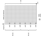
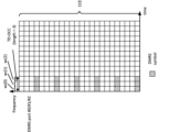
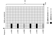
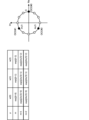
- Figure 1A shows an example of the number of UEs accommodated per slot/symbol for each channel.
- Figure 1A shows an example of the number of UEs accommodated per slot for each channel calculated based on the number of RBs.
- MCS modulation and coding scheme
- the number of UEs accommodated by PUSCH per slot in the case of MCS index 0, 10 RBs are required per UE, so the number of UEs accommodated is calculated to be 27. In addition, in the case of MCS index 5, 3 RBs are required per UE, so the number of UEs accommodated is calculated to be 91.
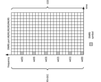
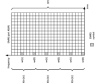
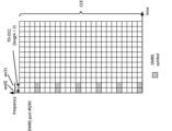
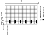
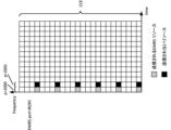
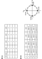
- Figure 1B shows an example of the number of UEs accommodated per cell for each channel.
- Figure 1B shows an example of the number of UEs accommodated per cell for each channel (the number of DCIs for PDCCH) calculated based on the TDD setting.
- a 1-symbol PDCCH can accommodate 392 DCIs (UL DCIs and DL DCIs), and a 2-symbol PDCCH can accommodate 784 DCIs (UL DCIs and DL DCIs).
- a 1-symbol PDCCH can accommodate 784 DCIs (UL DCIs and DL DCIs)
- a 2-symbol PDCCH can accommodate 1,568 DCIs (UL DCIs and DL DCIs).
- the number of UEs accommodated by the PUSCH per cell in the case of MCS index 0, 10 RBs are required per UE, so the number of UEs accommodated is calculated to be 216. In addition, in the case of MCS index 5, 3 RBs are required per UE, so the number of UEs accommodated is calculated to be 728.
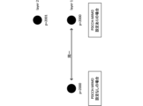
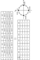
- a control channel e.g., PDCCH/DCI
- the number of PDCCHs/DCIs per cell is at least about 400, which is considered to be sufficiently large.
- PDCCH/DCI can be transmitted so that it is spread across all PDCCH resources.
- the base station In actual transmission, due to overbooking of PDCCH, the base station cannot simultaneously transmit as many PDCCHs as the number calculated above. In other words, if candidate resources for PDCCHs between UEs overlap in the time domain, a situation occurs in which PDCCH cannot be transmitted.
- A/B and “at least one of A and B” may be interpreted as interchangeable. Also, in this disclosure, “A/B/C” may mean “at least one of A, B, and C.”
- Radio Resource Control RRC
- RRC parameters RRC parameters
- RRC messages higher layer parameters, fields, information elements (IEs), settings, etc.
- IEs information elements
- CE Medium Access Control
- update commands activation/deactivation commands, etc.
- the higher layer signaling may be, for example, any one of Radio Resource Control (RRC) signaling, Medium Access Control (MAC) signaling, broadcast information, other messages (e.g., messages from the core network such as positioning protocols (e.g., NR Positioning Protocol A (NRPPa)/LTE Positioning Protocol (LPP)) messages), or a combination of these.
- RRC Radio Resource Control
- MAC Medium Access Control
- LPP LTE Positioning Protocol
- the MAC signaling may use, for example, a MAC Control Element (MAC CE), a MAC Protocol Data Unit (PDU), etc.
- the broadcast information may be, for example, a Master Information Block (MIB), a System Information Block (SIB), Remaining Minimum System Information (RMSI), Other System Information (OSI), etc.
- MIB Master Information Block
- SIB System Information Block
- RMSI Remaining Minimum System Information
- OSI System Information
- the physical layer signaling may be, for example, Downlink Control Information (DCI), Uplink Control Information (UCI), etc.
- DCI Downlink Control Information
- UCI Uplink Control Information
- the UE may receive the PDCCH with more than one rank/layer.
- the frequency resources e.g., aggregation level
- the frequency resources e.g., aggregation level
- the frequency resources e.g., aggregation level
- Each embodiment of the present disclosure may be applied only when certain parameters/fields are configured using higher layer signaling (e.g., RRC signaling/MAC CE).
- higher layer signaling e.g., RRC signaling/MAC CE.
- the number of receiving layers/ranks of the PDCCH may be configured for the UE using higher layer signaling, and the UE may receive DCI using the configured number of layers/ranks.
- the maximum number of layers/maximum ranks for receiving PDCCH may be set for the UE using higher layer signaling, and the UE may receive DCI using a number of layers/ranks equal to or less than the set maximum number of layers/maximum ranks.
- the configuration via the higher layer signaling may be performed, for example, per search space/per CORESET/per BWP/per CC/per band/per UE.
- Each embodiment of the present disclosure may be applied only when specific UE capability information (support for a specific UE capability) is reported.
- the UE capability information may be reported, for example, per band, per band combination (BC), per band within a BC, or per band within a BC and per CC (per CC per band in BC).
- Each embodiment of the present disclosure may be applied to a specific search space (SS)/SS set.
- the specific SS/SS set may be, for example, a UE-specific search space (USS) or a specific common search space (CSS, for example, type 3 CSS).
- USS UE-specific search space
- CSS common search space
- a configuration can be created that excludes CSSs for multiple UEs of types 0/0A/1/2.
- Figure 12 is a diagram showing an example of PDCCH DMRS to which TDM is applied.
- FIGS. 16A and 16B are diagrams showing other examples of OCC sequences.
- an example of an OCC using a Walsh matrix with a sequence length of 4 is shown
- an example of an OCC using a cyclic shift with a sequence length of 4 is shown.
- the OCC with a sequence length of 4 shown in FIG. 16A and 16B may be applied to the DMRS of a PDCCH.
- FIG. 17 is a diagram showing another example of an OCC sequence.
- an example of an OCC using a cyclic shift with a sequence length of 6 is shown.
- the OCC with a sequence length of 6 shown in FIG. 17 may be applied to the DMRS of a PDCCH.
- the third embodiment relates to the transmission power/power density of the PDCCH/DMRS.
- the transmission power for each symbol/RE is desirable for the transmission power for each symbol/RE to be constant.
- the power density e.g., Energy Per Resource Element (EPRE)
- EPRE Energy Per Resource Element
- the transmission power when some DMRS are not transmitted will be explained using FIG. 11 as an example again.
- the UE may be configured to not transmit some PDCCH/DMRS (resources/REs).
- the UE may be configured for PDCCH DMRS using the above FDM/TDM.
- the transmission power may be constant for time resources (e.g., symbols) of the DMRS/PDCCH when some DMRS/PDCCH (resources/REs) are not transmitted and for time resources (e.g., symbols) of the DMRS/PDCCH other than those time resources.
- the UE may assume that the transmission power of a DMRS/PDCCH time resource (e.g., symbol) when some DMRS/PDCCH (resources/REs) are not transmitted is determined based on the transmission power of the DMRS/PDCCH time resource (e.g., symbol) other than the time resource.
- a DMRS/PDCCH time resource e.g., symbol
- the power density (e.g., Effective Isotropic Radiated Power (EIRP)) of the PDCCH/DMRS in the symbol may be a specific number (e.g., N all /(N all -P)) times the power density of other symbols.
- EIRP Effective Isotropic Radiated Power
- the own UE may assume that the transmission power of resources excluding the power of the DMRS (resources/REs) for other UEs in a certain symbol is smaller than the transmission power of a symbol in which no DMRS is transmitted.
- the base station may control the transmission power of a symbol transmitting DMRS for multiple UEs to be equal to the transmission power of a symbol in which no DMRS is transmitted.
- FIG. 19 is a diagram showing an example of the transmission power of the PDCCH/DMRS according to the third embodiment.
- the example shown in FIG. 19 shows resources of 1 slot (14 symbols) and 1 CCE.
- the UE assumes that the transmission power/power density within 1 CCE in each symbol (symbols #0 to #2) in which some DMRS is not transmitted, and the transmission power/power density within 1 CCE in each other symbol are constant.
- the fourth embodiment relates to a precoder applied to a PDCCH.
- the UE may be configured/instructed as to whether or not the DMRS of the PDCCH is to be transmitted.
- the configuration/instruction may be performed, for example, using higher layer signaling (RRC/MAC CE)/DCI (e.g., previously received DCI).
- RRC/MAC CE higher layer signaling
- DCI previously received DCI
- the UE may not be notified of the precoder to be applied to the PDCCH.
- the UE may assume that the precoder to be applied to the PDCCH will not be notified.
- the precoder to be applied to the PDCCH does not need to be notified.
- the UE may assume/determine that the PDCCH and the DMRS of the PDCCH are transmitted using the same precoder.
- the UE may be notified of the precoder to be applied to the PDCCH.
- the UE may assume that the precoder to be applied to the PDCCH is notified.
- the precoder to be applied to the PDCCH may be notified.
- the UE may receive a cell-common/UE-common RS (e.g., CRS/CSI-RS/TRS) and be notified of the precoder (phase difference) of the PDCCH compared to the RS.
- a cell-common/UE-common RS e.g., CRS/CSI-RS/TRS
- the precoder may be notified, for example, using higher layer signaling (RRC/MAC CE)/DCI (e.g., previously received DCI).
- RRC/MAC CE higher layer signaling
- DCI previously received DCI
- the precoder to be applied to the PDCCH does not need to be notified.
- the UE may detect DCI from a specific precoder candidate using blind detection.
- the specific precoder candidate may be specified in advance in the specifications, or may be configured/instructed to the UE using higher layer signaling (RRC/MAC CE)/DCI.
- the network/base station may determine the precoder to be applied to the PDCCH using Channel Reciprocity based on UL reception from the UE (e.g., SRS/PUSCH/PUCCH/PUSCH DMRS/PUCCH DMRS).
- Channel Reciprocity based on UL reception from the UE (e.g., SRS/PUSCH/PUCCH/PUSCH DMRS/PUCCH DMRS).
- the network/base station may also decide to use a precoder determined based on CSI feedback for the PDSCH for the PDCCH.
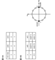
- the UE may assume that in the case of two ports/layers, linear polarization (e.g., vertical and horizontal polarization) is used for PDCCH transmission. Also, for example, the UE may assume that in the case of two ports/layers, circular polarization (e.g., right hand circular polarization (RHCP) and left hand circular polarization (LHCP)) is used for PDCCH transmission.
- linear polarization e.g., vertical and horizontal polarization
- circular polarization e.g., right hand circular polarization (RHCP) and left hand circular polarization (LHCP)
- the UE may assume that for 3 or 4 ports/layers, a combination of linear and circular polarization is used for PDCCH transmission.
- the UE may perform a report (e.g., CSI feedback) to determine the precoder of the PDCCH.
- the UE may receive a specific DL reference signal (e.g., CSI-RS/TRS) and generate/determine the report.
- the report may be performed, for example, using UCI/MAC CE (PUSCH).
- the report may be made only when PDCCH reception is configured using a number of layers/ports greater than (or equal to) a specific number of layers/ports (e.g., 2, 4).
- the report may be made only when PDCCH reception is configured using a number of layers/ports less than (or equal to) a specific number of layers/ports (e.g., 2, 4).
- the UE may receive an instruction (precoder instruction) from the network/base station to determine the precoder for the PDCCH.
- the instruction may be given, for example, using DCI/MAC CE.
- the instruction may be sent based on a report from the UE.
- the fifth embodiment relates to operation using multiple TRPs.
- a PDCCH using multiple layers/ports may be configured for the UE.
- Each PDCCH port/layer may correspond to a (different/same) TCI state.
- the correspondence of the TCI state may be set/indicated using higher layer signaling (RRC/MAC CE)/DCI.
- TRPs may be associated with one PDCCH port/layer.
- the number of paths can be increased, thereby improving the expected performance rank and improving performance.
- the above-mentioned embodiments may be applied when the UE configures/activates/triggers specific information related to the above-mentioned embodiments (or performs the operations of the above-mentioned embodiments) by higher layer signaling/physical layer signaling.
- the specific information may be information indicating that reception of PDCCH using multi-layer/port/rank is enabled, any RRC parameters for a specific release (e.g., Rel. 18/19), etc.
- the UE may, for example, apply Rel. 15/16 operations.
- Appendix A With respect to one embodiment of the present disclosure, the following invention is noted.
- Appendix A-1 A terminal having a receiving unit that receives a setting regarding the number or maximum number of layers to be used for receiving a physical downlink control channel (PDCCH) using multiple layers, and a control unit that controls reception of the PDCCH using the multiple layers based on the setting.
- Appendix A-2 The terminal according to appendix A-1, wherein the control unit determines that a layer having a smaller or larger number among the plurality of layers has a higher priority.
- a terminal having a receiver that receives a demodulation reference signal (DMRS) of a physical downlink control channel (PDCCH) using multiple layers, the DMRS being mapped using a frequency domain orthogonal cover code (FD-OCC), a time domain OCC (TD-OCC), a frequency domain and time domain OCC, frequency division multiplexing (FDM), or time division multiplexing (TDM), and a control unit that controls reception of the PDCCH based on the DMRS.
- DMRS demodulation reference signal
- PDCCH physical downlink control channel
- FD-OCC frequency domain orthogonal cover code
- TD-OCC time domain OCC
- FDM frequency division multiplexing
- TDM time division multiplexing
- Appendix B-2 The terminal according to Supplementary Note B-1, wherein the control unit determines that an antenna port number for a first layer among the plurality of layers and an antenna port number corresponding to a PDCCH that does not use the plurality of layers are identical.
- Appendix B-3 The terminal described in Appendix B-1 or Appendix B-2, wherein the receiving unit receives a first setting regarding the number of the multiple layers and a second setting regarding antenna port numbers corresponding to the PDCCH and the DMRS, and the control unit detects downlink control information transmitted on the PDCCH based on the first setting and the second setting.
- Appendix B-4 A terminal described in any one of Supplementary Notes B-1 to B-3, in which, when a DMRS symbol corresponding to a specific port is not transmitted in a symbol in which the DMRS using the FDM or the DMRS using the TDM is transmitted, the control unit assumes that the power density in a time resource of the DMRS symbol is equal to the power density in a time resource other than the time resource.
- Wired communication system A configuration of a wireless communication system according to an embodiment of the present disclosure will be described below.
- communication is performed using any one of the wireless communication methods according to the above embodiments of the present disclosure or a combination of these.
- FIG. 20 is a diagram showing an example of a schematic configuration of a wireless communication system according to an embodiment.
- the wireless communication system 1 (which may simply be referred to as system 1) may be a system that realizes communication using Long Term Evolution (LTE) specified by the Third Generation Partnership Project (3GPP), 5th generation mobile communication system New Radio (5G NR), or the like.
- LTE Long Term Evolution
- 3GPP Third Generation Partnership Project
- 5G NR 5th generation mobile communication system New Radio
- the wireless communication system 1 may also support dual connectivity between multiple Radio Access Technologies (RATs) (Multi-RAT Dual Connectivity (MR-DC)).
- MR-DC may include dual connectivity between LTE (Evolved Universal Terrestrial Radio Access (E-UTRA)) and NR (E-UTRA-NR Dual Connectivity (EN-DC)), dual connectivity between NR and LTE (NR-E-UTRA Dual Connectivity (NE-DC)), etc.
- RATs Radio Access Technologies
- MR-DC may include dual connectivity between LTE (Evolved Universal Terrestrial Radio Access (E-UTRA)) and NR (E-UTRA-NR Dual Connectivity (EN-DC)), dual connectivity between NR and LTE (NR-E-UTRA Dual Connectivity (NE-DC)), etc.
- E-UTRA Evolved Universal Terrestrial Radio Access
- EN-DC E-UTRA-NR Dual Connectivity
- NE-DC NR-E-UTRA Dual Connectivity
- the LTE (E-UTRA) base station (eNB) is the master node (MN), and the NR base station (gNB) is the secondary node (SN).
- the NR base station (gNB) is the MN, and the LTE (E-UTRA) base station (eNB) is the SN.
- the wireless communication system 1 may support dual connectivity between multiple base stations within the same RAT (e.g., dual connectivity in which both the MN and SN are NR base stations (gNBs) (NR-NR Dual Connectivity (NN-DC))).
- dual connectivity in which both the MN and SN are NR base stations (gNBs) (NR-NR Dual Connectivity (NN-DC))).
- gNBs NR base stations
- N-DC Dual Connectivity
- the wireless communication system 1 may include a base station 11 that forms a macrocell C1 with a relatively wide coverage, and base stations 12 (12a-12c) that are arranged within the macrocell C1 and form a small cell C2 that is narrower than the macrocell C1.
- a user terminal 20 may be located within at least one of the cells. The arrangement and number of each cell and user terminal 20 are not limited to the embodiment shown in the figure. Hereinafter, when there is no need to distinguish between the base stations 11 and 12, they will be collectively referred to as base station 10.
- the user terminal 20 may be connected to at least one of the multiple base stations 10.
- the user terminal 20 may utilize at least one of carrier aggregation (CA) using multiple component carriers (CC) and dual connectivity (DC).
- CA carrier aggregation
- CC component carriers
- DC dual connectivity
- Each CC may be included in at least one of a first frequency band (Frequency Range 1 (FR1)) and a second frequency band (Frequency Range 2 (FR2)).
- Macro cell C1 may be included in FR1
- small cell C2 may be included in FR2.
- FR1 may be a frequency band below 6 GHz (sub-6 GHz)
- FR2 may be a frequency band above 24 GHz (above-24 GHz). Note that the frequency bands and definitions of FR1 and FR2 are not limited to these, and for example, FR1 may correspond to a higher frequency band than FR2.
- the user terminal 20 may communicate using at least one of Time Division Duplex (TDD) and Frequency Division Duplex (FDD) in each CC.
- TDD Time Division Duplex
- FDD Frequency Division Duplex
- the multiple base stations 10 may be connected by wire (e.g., optical fiber conforming to the Common Public Radio Interface (CPRI), X2 interface, etc.) or wirelessly (e.g., NR communication).
- wire e.g., optical fiber conforming to the Common Public Radio Interface (CPRI), X2 interface, etc.
- NR communication e.g., NR communication
- base station 11 which corresponds to the upper station
- IAB Integrated Access Backhaul
- base station 12 which corresponds to a relay station
- the base station 10 may be connected to the core network 30 via another base station 10 or directly.
- the core network 30 may include, for example, at least one of an Evolved Packet Core (EPC), a 5G Core Network (5GCN), a Next Generation Core (NGC), etc.
- EPC Evolved Packet Core
- 5GCN 5G Core Network
- NGC Next Generation Core
- the core network 30 may include network functions (Network Functions (NF)) such as, for example, a User Plane Function (UPF), an Access and Mobility management Function (AMF), a Session Management Function (SMF), a Unified Data Management (UDM), an Application Function (AF), a Data Network (DN), a Location Management Function (LMF), and Operation, Administration and Maintenance (Management) (OAM).
- NF Network Functions
- UPF User Plane Function
- AMF Access and Mobility management Function
- SMF Session Management Function
- UDM Unified Data Management
- AF Application Function
- DN Data Network
- LMF Location Management Function
- OAM Operation, Administration and Maintenance
- the user terminal 20 may be a terminal that supports at least one of the communication methods such as LTE, LTE-A, and 5G.
- a wireless access method based on Orthogonal Frequency Division Multiplexing may be used.
- OFDM Orthogonal Frequency Division Multiplexing
- CP-OFDM Cyclic Prefix OFDM
- DFT-s-OFDM Discrete Fourier Transform Spread OFDM
- OFDMA Orthogonal Frequency Division Multiple Access
- SC-FDMA Single Carrier Frequency Division Multiple Access
- the radio access method may also be called a waveform.
- other radio access methods e.g., other single-carrier transmission methods, other multi-carrier transmission methods
- a downlink shared channel (Physical Downlink Shared Channel (PDSCH)) shared by each user terminal 20, a broadcast channel (Physical Broadcast Channel (PBCH)), a downlink control channel (Physical Downlink Control Channel (PDCCH)), etc. may be used as the downlink channel.
- PDSCH Physical Downlink Shared Channel
- PBCH Physical Broadcast Channel
- PDCCH Physical Downlink Control Channel
- an uplink shared channel (Physical Uplink Shared Channel (PUSCH)) shared by each user terminal 20, an uplink control channel (Physical Uplink Control Channel (PUCCH)), a random access channel (Physical Random Access Channel (PRACH)), etc. may be used as an uplink channel.
- PUSCH Physical Uplink Shared Channel
- PUCCH Physical Uplink Control Channel
- PRACH Physical Random Access Channel
- SIB System Information Block
- PDSCH User data, upper layer control information, System Information Block (SIB), etc.
- SIB System Information Block
- PUSCH User data, upper layer control information, etc.
- MIB Master Information Block
- PBCH Physical Broadcast Channel
- Lower layer control information may be transmitted by the PDCCH.
- the lower layer control information may include, for example, downlink control information (Downlink Control Information (DCI)) including scheduling information for at least one of the PDSCH and the PUSCH.
- DCI Downlink Control Information
- the DCI for scheduling the PDSCH may be called a DL assignment or DL DCI
- the DCI for scheduling the PUSCH may be called a UL grant or UL DCI.
- the PDSCH may be interpreted as DL data
- the PUSCH may be interpreted as UL data.
- a control resource set (COntrol REsource SET (CORESET)) and a search space may be used to detect the PDCCH.
- the CORESET corresponds to the resources to search for DCI.
- the search space corresponds to the search region and search method of PDCCH candidates.
- One CORESET may be associated with one or multiple search spaces. The UE may monitor the CORESET associated with a certain search space based on the search space configuration.
- a search space may correspond to PDCCH candidates corresponding to one or more aggregation levels.
- One or more search spaces may be referred to as a search space set. Note that the terms “search space,” “search space set,” “search space setting,” “search space set setting,” “CORESET,” “CORESET setting,” etc. in this disclosure may be read as interchangeable.
- the PUCCH may transmit uplink control information (UCI) including at least one of channel state information (CSI), delivery confirmation information (which may be called, for example, Hybrid Automatic Repeat reQuest ACKnowledgement (HARQ-ACK), ACK/NACK, etc.), and a scheduling request (SR).
- UCI uplink control information
- CSI channel state information
- HARQ-ACK Hybrid Automatic Repeat reQuest ACKnowledgement
- ACK/NACK ACK/NACK
- SR scheduling request
- the PRACH may transmit a random access preamble for establishing a connection with a cell.
- downlink, uplink, etc. may be expressed without adding "link.”
- various channels may be expressed without adding "Physical” to the beginning.
- a synchronization signal (SS), a downlink reference signal (DL-RS), etc. may be transmitted.
- a cell-specific reference signal (CRS), a channel state information reference signal (CSI-RS), a demodulation reference signal (DMRS), a positioning reference signal (PRS), a phase tracking reference signal (PTRS), etc. may be transmitted.
- the synchronization signal may be, for example, at least one of a Primary Synchronization Signal (PSS) and a Secondary Synchronization Signal (SSS).
- a signal block including an SS (PSS, SSS) and a PBCH (and a DMRS for PBCH) may be called an SS/PBCH block, an SS Block (SSB), etc.
- SS, SSB, etc. may also be called reference signals.
- a measurement reference signal Sounding Reference Signal (SRS)
- a demodulation reference signal DMRS
- UL-RS uplink reference signal
- DMRS may also be called a user equipment-specific reference signal (UE-specific Reference Signal).
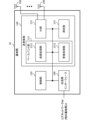
- the base station 21 is a diagram showing an example of a configuration of a base station according to an embodiment.
- the base station 10 includes a control unit 110, a transceiver unit 120, a transceiver antenna 130, and a transmission line interface 140. Note that one or more of each of the control unit 110, the transceiver unit 120, the transceiver antenna 130, and the transmission line interface 140 may be provided.
- this example mainly shows the functional blocks of the characteristic parts of this embodiment, and the base station 10 may also be assumed to have other functional blocks necessary for wireless communication. Some of the processing of each part described below may be omitted.
- the control unit 110 controls the entire base station 10.
- the control unit 110 can be configured from a controller, a control circuit, etc., which are described based on a common understanding in the technical field to which this disclosure pertains.
- the control unit 110 may control signal generation, scheduling (e.g., resource allocation, mapping), etc.
- the control unit 110 may control transmission and reception using the transceiver unit 120, the transceiver antenna 130, and the transmission path interface 140, measurement, etc.
- the control unit 110 may generate data, control information, sequences, etc. to be transmitted as signals, and transfer them to the transceiver unit 120.
- the control unit 110 may perform call processing of communication channels (setting, release, etc.), status management of the base station 10, management of radio resources, etc.
- the transceiver unit 120 may include a baseband unit 121, a radio frequency (RF) unit 122, and a measurement unit 123.
- the baseband unit 121 may include a transmission processing unit 1211 and a reception processing unit 1212.
- the transceiver unit 120 may be composed of a transmitter/receiver, an RF circuit, a baseband circuit, a filter, a phase shifter, a measurement circuit, a transceiver circuit, etc., which are described based on a common understanding in the technical field to which the present disclosure relates.
- the transceiver unit 120 may be configured as an integrated transceiver unit, or may be composed of a transmission unit and a reception unit.
- the transmission unit may be composed of a transmission processing unit 1211 and an RF unit 122.
- the reception unit may be composed of a reception processing unit 1212, an RF unit 122, and a measurement unit 123.
- the transmitting/receiving antenna 130 can be configured as an antenna described based on common understanding in the technical field to which this disclosure pertains, such as an array antenna.
- the transceiver 120 may transmit the above-mentioned downlink channel, synchronization signal, downlink reference signal, etc.
- the transceiver 120 may receive the above-mentioned uplink channel, uplink reference signal, etc.
- the transceiver 120 may perform Packet Data Convergence Protocol (PDCP) layer processing, Radio Link Control (RLC) layer processing (e.g., RLC retransmission control), Medium Access Control (MAC) layer processing (e.g., HARQ retransmission control), etc. on data and control information obtained from the control unit 110 to generate a bit string to be transmitted.
- PDCP Packet Data Convergence Protocol
- RLC Radio Link Control
- MAC Medium Access Control
- HARQ retransmission control HARQ retransmission control
- the transceiver unit 120 may perform transmission processing such as channel coding (which may include error correction coding), modulation, mapping, filtering, Discrete Fourier Transform (DFT) processing (if necessary), Inverse Fast Fourier Transform (IFFT) processing, precoding, and digital-to-analog conversion on the bit string to be transmitted, and output a baseband signal.
- transmission processing such as channel coding (which may include error correction coding), modulation, mapping, filtering, Discrete Fourier Transform (DFT) processing (if necessary), Inverse Fast Fourier Transform (IFFT) processing, precoding, and digital-to-analog conversion on the bit string to be transmitted, and output a baseband signal.
- channel coding which may include error correction coding
- DFT Discrete Fourier Transform
- IFFT Inverse Fast Fourier Transform
- the transceiver unit 120 may perform amplification, filtering, demodulation to a baseband signal, etc. on the radio frequency band signal received by the transceiver antenna 130.
- the transceiver 120 may perform measurements on the received signal.
- the measurement unit 123 may perform Radio Resource Management (RRM) measurements, Channel State Information (CSI) measurements, etc. based on the received signal.
- the measurement unit 123 may measure received power (e.g., Reference Signal Received Power (RSRP)), received quality (e.g., Reference Signal Received Quality (RSRQ), Signal to Interference plus Noise Ratio (SINR), Signal to Noise Ratio (SNR)), signal strength (e.g., Received Signal Strength Indicator (RSSI)), propagation path information (e.g., CSI), etc.
- RSRP Reference Signal Received Power
- RSSI Received Signal Strength Indicator
- the measurement results may be output to the control unit 110.
- the transmission path interface 140 may transmit and receive signals (backhaul signaling) between devices included in the core network 30 (e.g., network nodes providing NF), other base stations 10, etc., and may acquire and transmit user data (user plane data), control plane data, etc. for the user terminal 20.
- devices included in the core network 30 e.g., network nodes providing NF
- other base stations 10, etc. may acquire and transmit user data (user plane data), control plane data, etc. for the user terminal 20.
- the transmitting unit and receiving unit of the base station 10 in this disclosure may be configured by at least one of the transmitting/receiving unit 120, the transmitting/receiving antenna 130, and the transmission path interface 140.
- the transceiver 120 may transmit a setting regarding the number or maximum number of layers to be used for receiving a physical downlink control channel (PDCCH) using multiple layers.
- the control unit 110 may use the setting to control the transmission of the PDCCH using the multiple layers (first embodiment).
- the transceiver unit 120 may transmit a demodulation reference signal (DMRS) for a physical downlink control channel (PDCCH) using multiple layers, the DMRS being mapped using a frequency domain orthogonal cover code (FD-OCC), a time domain OCC (TD-OCC), a frequency domain and a time domain OCC, frequency division multiplexing (FDM), or time division multiplexing (TDM).
- DMRS demodulation reference signal
- PDCCH physical downlink control channel
- FD-OCC frequency domain orthogonal cover code
- TD-OCC time domain OCC
- FDM frequency division multiplexing
- TDM time division multiplexing
- the control unit 110 may use the DMRS to instruct the reception processing of the PDCCH (second embodiment).
- the user terminal 22 is a diagram showing an example of the configuration of a user terminal according to an embodiment.
- the user terminal 20 includes a control unit 210, a transmitting/receiving unit 220, and a transmitting/receiving antenna 230.
- the control unit 210, the transmitting/receiving unit 220, and the transmitting/receiving antenna 230 may each include one or more.
- this example mainly shows the functional blocks of the characteristic parts of this embodiment, and the user terminal 20 may also be assumed to have other functional blocks necessary for wireless communication. Some of the processing of each part described below may be omitted.
- the control unit 210 controls the entire user terminal 20.
- the control unit 210 can be configured from a controller, a control circuit, etc., which are described based on a common understanding in the technical field to which this disclosure pertains.
- the control unit 210 may control signal generation, mapping, etc.
- the control unit 210 may control transmission and reception using the transceiver unit 220 and the transceiver antenna 230, measurement, etc.
- the control unit 210 may generate data, control information, sequences, etc. to be transmitted as signals, and transfer them to the transceiver unit 220.
- the transceiver unit 220 may include a baseband unit 221, an RF unit 222, and a measurement unit 223.
- the baseband unit 221 may include a transmission processing unit 2211 and a reception processing unit 2212.
- the transceiver unit 220 may be composed of a transmitter/receiver, an RF circuit, a baseband circuit, a filter, a phase shifter, a measurement circuit, a transceiver circuit, etc., which are described based on a common understanding in the technical field to which the present disclosure relates.
- the transceiver unit 220 may be configured as an integrated transceiver unit, or may be composed of a transmission unit and a reception unit.
- the transmission unit may be composed of a transmission processing unit 2211 and an RF unit 222.
- the reception unit may be composed of a reception processing unit 2212, an RF unit 222, and a measurement unit 223.
- the transmitting/receiving antenna 230 can be configured as an antenna described based on common understanding in the technical field to which this disclosure pertains, such as an array antenna.
- the transceiver 220 may receive the above-mentioned downlink channel, synchronization signal, downlink reference signal, etc.
- the transceiver 220 may transmit the above-mentioned uplink channel, uplink reference signal, etc.
- the transceiver unit 220 may form at least one of the transmit beam and the receive beam using digital beamforming (e.g., precoding), analog beamforming (e.g., phase rotation), etc.
- digital beamforming e.g., precoding
- analog beamforming e.g., phase rotation
- the transceiver 220 may perform PDCP layer processing, RLC layer processing (e.g., RLC retransmission control), MAC layer processing (e.g., HARQ retransmission control), etc. on the data and control information acquired from the controller 210, and generate a bit string to be transmitted.
- RLC layer processing e.g., RLC retransmission control
- MAC layer processing e.g., HARQ retransmission control
- the transceiver 220 may perform transmission processing such as channel coding (which may include error correction coding), modulation, mapping, filtering, DFT processing (if necessary), IFFT processing, precoding, and digital-to-analog conversion on the bit string to be transmitted, and output a baseband signal.
- transmission processing such as channel coding (which may include error correction coding), modulation, mapping, filtering, DFT processing (if necessary), IFFT processing, precoding, and digital-to-analog conversion on the bit string to be transmitted, and output a baseband signal.
- Whether or not to apply DFT processing may be based on the settings of transform precoding.
- the transceiver unit 220 transmission processing unit 2211
- the transceiver unit 220 may perform DFT processing as the above-mentioned transmission processing in order to transmit the channel using a DFT-s-OFDM waveform, and when transform precoding is not enabled, it is not necessary to perform DFT processing as the above-mentioned transmission processing.
- the transceiver unit 220 may perform modulation, filtering, amplification, etc., on the baseband signal to a radio frequency band, and transmit the radio frequency band signal via the transceiver antenna 230.
- the transceiver unit 220 may perform amplification, filtering, demodulation to a baseband signal, etc. on the radio frequency band signal received by the transceiver antenna 230.
- the transceiver 220 may perform measurements on the received signal. For example, the measurement unit 223 may perform RRM measurements, CSI measurements, etc. based on the received signal.
- the measurement unit 223 may measure received power (e.g., RSRP), received quality (e.g., RSRQ, SINR, SNR), signal strength (e.g., RSSI), propagation path information (e.g., CSI), etc.
- the measurement results may be output to the control unit 210.
- the transceiver 220 may receive a setting regarding the number or maximum number of layers to be used for receiving a physical downlink control channel (PDCCH) using multiple layers.
- the control unit 210 may control the reception of the PDCCH using the multiple layers based on the setting (first embodiment).
- the control unit 210 may determine that a layer with a lower or higher number among the multiple layers has a higher priority (first embodiment).
- the transceiver unit 220 may receive information regarding a precoder to be applied to the PDCCH. If the demodulation reference signal is transmitted, the control unit 210 may assume that the PDCCH and the demodulation reference signal are transmitted using the same precoder (fourth embodiment).
- the multiple layers may correspond to different transmission configuration indication (TCI) states (fifth embodiment).
- TCI transmission configuration indication
- the transceiver unit 220 may receive a demodulation reference signal (DMRS) of a physical downlink control channel (PDCCH) using multiple layers, the DMRS being mapped using a frequency domain orthogonal cover code (FD-OCC), a time domain OCC (TD-OCC), a frequency domain and a time domain OCC, frequency division multiplexing (FDM), or time division multiplexing (TDM).
- DMRS demodulation reference signal
- PDCCH physical downlink control channel
- FD-OCC frequency domain orthogonal cover code
- TD-OCC time domain OCC
- FDM frequency division multiplexing
- TDM time division multiplexing
- the control unit 210 may control reception of the PDCCH based on the DMRS (second embodiment).
- the control unit 210 may determine that the antenna port number for the first layer of the multiple layers is the same as the antenna port number corresponding to a PDCCH that does not use the multiple layers (second embodiment).
- the transceiver 220 may receive a first setting related to the number of the layers and a second setting related to the antenna port numbers corresponding to the PDCCH and the DMRS.
- the controller 210 may detect downlink control information transmitted on the PDCCH based on the first setting and the second setting (second embodiment).
- control unit 210 may assume that the power density in the time resource of the DMRS symbol is equal to the power density in a time resource other than the time resource (third embodiment).
- each functional block may be realized using one device that is physically or logically coupled, or may be realized using two or more devices that are physically or logically separated and directly or indirectly connected (for example, using wires, wirelessly, etc.).
- the functional blocks may be realized by combining the one device or the multiple devices with software.
- the functions include, but are not limited to, judgement, determination, judgment, calculation, computation, processing, derivation, investigation, search, confirmation, reception, transmission, output, access, resolution, selection, selection, establishment, comparison, assumption, expectation, deeming, broadcasting, notifying, communicating, forwarding, configuring, reconfiguring, allocating, mapping, and assignment.
- a functional block (component) that performs the transmission function may be called a transmitting unit, a transmitter, and the like. In either case, as mentioned above, there are no particular limitations on the method of realization.
- a base station, a user terminal, etc. in one embodiment of the present disclosure may function as a computer that performs processing of the wireless communication method of the present disclosure.
- FIG. 23 is a diagram showing an example of the hardware configuration of a base station and a user terminal according to one embodiment.
- the above-mentioned base station 10 and user terminal 20 may be physically configured as a computer device including a processor 1001, a memory 1002, a storage 1003, a communication device 1004, an input device 1005, an output device 1006, a bus 1007, etc.
- the terms apparatus, circuit, device, section, unit, etc. may be interpreted as interchangeable.
- the hardware configurations of the base station 10 and the user terminal 20 may be configured to include one or more of the devices shown in the figures, or may be configured to exclude some of the devices.
- processor 1001 may be implemented by one or more chips.
- the functions of the base station 10 and the user terminal 20 are realized, for example, by loading specific software (programs) onto hardware such as the processor 1001 and memory 1002, causing the processor 1001 to perform calculations, control communications via the communication device 1004, and control at least one of the reading and writing of data in the memory 1002 and storage 1003.
- the processor 1001 for example, runs an operating system to control the entire computer.
- the processor 1001 may be configured as a central processing unit (CPU) including an interface with peripheral devices, a control device, an arithmetic unit, registers, etc.
- CPU central processing unit
- control unit 110 210
- transmission/reception unit 120 220
- etc. may be realized by the processor 1001.
- the processor 1001 also reads out programs (program codes), software modules, data, etc. from at least one of the storage 1003 and the communication device 1004 into the memory 1002, and executes various processes according to these.
- the programs used are those that cause a computer to execute at least some of the operations described in the above embodiments.
- the control unit 110 (210) may be realized by a control program stored in the memory 1002 and running on the processor 1001, and similar implementations may be made for other functional blocks.
- Memory 1002 is a computer-readable recording medium and may be composed of at least one of, for example, Read Only Memory (ROM), Erasable Programmable ROM (EPROM), Electrically EPROM (EEPROM), Random Access Memory (RAM), and other suitable storage media. Memory 1002 may also be called a register, cache, main memory, etc. Memory 1002 can store executable programs (program codes), software modules, etc. for implementing a wireless communication method according to one embodiment of the present disclosure.
- ROM Read Only Memory
- EPROM Erasable Programmable ROM
- EEPROM Electrically EPROM
- RAM Random Access Memory
- Memory 1002 may also be called a register, cache, main memory, etc.
- Memory 1002 can store executable programs (program codes), software modules, etc. for implementing a wireless communication method according to one embodiment of the present disclosure.
- Storage 1003 is a computer-readable recording medium and may be composed of at least one of a flexible disk, a floppy disk, a magneto-optical disk (e.g., a compact disk (Compact Disc ROM (CD-ROM)), a digital versatile disk, a Blu-ray disk), a removable disk, a hard disk drive, a smart card, a flash memory device (e.g., a card, a stick, a key drive), a magnetic stripe, a database, a server, or other suitable storage medium.
- Storage 1003 may also be referred to as an auxiliary storage device.
- the communication device 1004 is hardware (transmitting/receiving device) for communicating between computers via at least one of a wired network and a wireless network, and is also called, for example, a network device, a network controller, a network card, a communication module, etc.
- the communication device 1004 may be configured to include a high-frequency switch, a duplexer, a filter, a frequency synthesizer, etc. to realize at least one of, for example, Frequency Division Duplex (FDD) and Time Division Duplex (TDD).
- FDD Frequency Division Duplex
- TDD Time Division Duplex
- the above-mentioned transmitting/receiving unit 120 (220), transmitting/receiving antenna 130 (230), etc. may be realized by the communication device 1004.
- the transmitting/receiving unit 120 (220) may be implemented as a transmitting unit 120a (220a) and a receiving unit 120b (220b) that are physically or logically separated.
- the input device 1005 is an input device (e.g., a keyboard, a mouse, a microphone, a switch, a button, a sensor, etc.) that accepts input from the outside.
- the output device 1006 is an output device (e.g., a display, a speaker, a Light Emitting Diode (LED) lamp, etc.) that outputs to the outside.
- the input device 1005 and the output device 1006 may be integrated into one structure (e.g., a touch panel).
- each device such as the processor 1001 and memory 1002 is connected by a bus 1007 for communicating information.
- the bus 1007 may be configured using a single bus, or may be configured using different buses between each device.
- the base station 10 and the user terminal 20 may be configured to include hardware such as a microprocessor, a digital signal processor (DSP), an application specific integrated circuit (ASIC), a programmable logic device (PLD), or a field programmable gate array (FPGA), and some or all of the functional blocks may be realized using the hardware.
- the processor 1001 may be implemented using at least one of these pieces of hardware.
- a channel, a symbol, and a signal may be read as mutually interchangeable.
- a signal may also be a message.
- a reference signal may be abbreviated as RS, and may be called a pilot, a pilot signal, or the like depending on the applied standard.
- a component carrier may also be called a cell, a frequency carrier, a carrier frequency, or the like.
- a radio frame may be composed of one or more periods (frames) in the time domain.
- Each of the one or more periods (frames) constituting a radio frame may be called a subframe.
- a subframe may be composed of one or more slots in the time domain.
- a subframe may have a fixed time length (e.g., 1 ms) that is independent of numerology.
- the numerology may be a communication parameter that is applied to at least one of the transmission and reception of a signal or channel.
- the numerology may indicate, for example, at least one of the following: SubCarrier Spacing (SCS), bandwidth, symbol length, cyclic prefix length, Transmission Time Interval (TTI), number of symbols per TTI, radio frame configuration, a specific filtering process performed by the transceiver in the frequency domain, a specific windowing process performed by the transceiver in the time domain, etc.
- SCS SubCarrier Spacing
- TTI Transmission Time Interval
- radio frame configuration a specific filtering process performed by the transceiver in the frequency domain
- a specific windowing process performed by the transceiver in the time domain etc.
- a slot may consist of one or more symbols in the time domain (such as Orthogonal Frequency Division Multiplexing (OFDM) symbols, Single Carrier Frequency Division Multiple Access (SC-FDMA) symbols, etc.).
- OFDM Orthogonal Frequency Division Multiplexing
- SC-FDMA Single Carrier Frequency Division Multiple Access
- a slot may also be a time unit based on numerology.
- a slot may include multiple minislots. Each minislot may consist of one or multiple symbols in the time domain. A minislot may also be called a subslot. A minislot may consist of fewer symbols than a slot.
- a PDSCH (or PUSCH) transmitted in a time unit larger than a minislot may be called PDSCH (PUSCH) mapping type A.
- a PDSCH (or PUSCH) transmitted using a minislot may be called PDSCH (PUSCH) mapping type B.
- a radio frame, subframe, slot, minislot, and symbol all represent time units when transmitting a signal.
- a different name may be used for radio frame, subframe, slot, minislot, and symbol. Note that the time units such as frame, subframe, slot, minislot, and symbol in this disclosure may be read as interchangeable.
- one subframe may be called a TTI
- multiple consecutive subframes may be called a TTI
- one slot or one minislot may be called a TTI.
- at least one of the subframe and the TTI may be a subframe (1 ms) in existing LTE, a period shorter than 1 ms (e.g., 1-13 symbols), or a period longer than 1 ms.
- the unit representing the TTI may be called a slot, minislot, etc., instead of a subframe.
- TTI refers to, for example, the smallest time unit for scheduling in wireless communication.
- a base station schedules each user terminal by allocating radio resources (such as frequency bandwidth and transmission power that can be used by each user terminal) in TTI units.
- radio resources such as frequency bandwidth and transmission power that can be used by each user terminal
- the TTI may be a transmission time unit for a channel-coded data packet (transport block), a code block, a code word, etc., or may be a processing unit for scheduling, link adaptation, etc.
- the time interval e.g., the number of symbols
- the time interval in which a transport block, a code block, a code word, etc. is actually mapped may be shorter than the TTI.
- a TTI having a time length of 1 ms may be called a normal TTI (TTI in 3GPP Rel. 8-12), normal TTI, long TTI, normal subframe, normal subframe, long subframe, slot, etc.
- a TTI shorter than a normal TTI may be called a shortened TTI, short TTI, partial or fractional TTI, shortened subframe, short subframe, minislot, subslot, slot, etc.
- an RB may include one or more symbols in the time domain and may be one slot, one minislot, one subframe, or one TTI in length.
- One TTI, one subframe, etc. may each be composed of one or more resource blocks.
- a resource block may be composed of one or more resource elements (REs).
- REs resource elements
- one RE may be a radio resource area of one subcarrier and one symbol.
- a Bandwidth Part which may also be referred to as partial bandwidth, may represent a subset of contiguous common resource blocks (RBs) for a given numerology on a given carrier, where the common RBs may be identified by an index of the RB relative to a common reference point of the carrier.
- PRBs may be defined in a BWP and numbered within the BWP.
- the BWP may include a UL BWP (BWP for UL) and a DL BWP (BWP for DL).
- BWP UL BWP
- BWP for DL DL BWP
- One or more BWPs may be configured for a UE within one carrier.
- At least one of the configured BWPs may be active, and the UE may not expect to transmit or receive a given signal/channel outside the active BWP.
- BWP bitmap
- radio frames, subframes, slots, minislots, and symbols are merely examples.
- the number of subframes included in a radio frame, the number of slots per subframe or radio frame, the number of minislots included in a slot, the number of symbols and RBs included in a slot or minislot, the number of subcarriers included in an RB, as well as the number of symbols in a TTI, the symbol length, and the cyclic prefix (CP) length can be changed in various ways.
- the information, parameters, etc. described in this disclosure may be represented using absolute values, may be represented using relative values from a predetermined value, or may be represented using other corresponding information.
- a radio resource may be indicated by a predetermined index.
- the names used for parameters, etc. in this disclosure are not limiting in any respect. Furthermore, the formulas, etc. using these parameters may differ from those explicitly disclosed in this disclosure.
- the various channels (PUCCH, PDCCH, etc.) and information elements may be identified by any suitable names, and therefore the various names assigned to these various channels and information elements are not limiting in any respect.
- the information, signals, etc. described in this disclosure may be represented using any of a variety of different technologies.
- the data, instructions, commands, information, signals, bits, symbols, chips, etc. that may be referred to throughout the above description may be represented by voltages, currents, electromagnetic waves, magnetic fields or magnetic particles, optical fields or photons, or any combination thereof.
- Input/output information, signals, etc. may be stored in a specific location (e.g., memory) or may be managed using a management table. Input/output information, signals, etc. may be overwritten, updated, or added to. Output information, signals, etc. may be deleted. Input information, signals, etc. may be transmitted to another device.
- a specific location e.g., memory
- Input/output information, signals, etc. may be overwritten, updated, or added to.
- Output information, signals, etc. may be deleted.
- Input information, signals, etc. may be transmitted to another device.
- the notification of information is not limited to the aspects/embodiments described in this disclosure, and may be performed using other methods.
- the notification of information in this disclosure may be performed by physical layer signaling (e.g., Downlink Control Information (DCI), Uplink Control Information (UCI)), higher layer signaling (e.g., Radio Resource Control (RRC) signaling, broadcast information (Master Information Block (MIB), System Information Block (SIB)), etc.), Medium Access Control (MAC) signaling), other signals, or a combination of these.
- DCI Downlink Control Information
- UCI Uplink Control Information
- RRC Radio Resource Control
- MIB Master Information Block
- SIB System Information Block
- MAC Medium Access Control
- the physical layer signaling may be called Layer 1/Layer 2 (L1/L2) control information (L1/L2 control signal), L1 control information (L1 control signal), etc.
- the RRC signaling may be called an RRC message, for example, an RRC Connection Setup message, an RRC Connection Reconfiguration message, etc.
- the MAC signaling may be notified, for example, using a MAC Control Element (CE).
- CE MAC Control Element
- notification of specified information is not limited to explicit notification, but may be implicit (e.g., by not notifying the specified information or by notifying other information).
- the determination may be based on a value represented by a single bit (0 or 1), a Boolean value represented by true or false, or a comparison of numerical values (e.g., with a predetermined value).
- Software shall be construed broadly to mean instructions, instruction sets, code, code segments, program code, programs, subprograms, software modules, applications, software applications, software packages, routines, subroutines, objects, executable files, threads of execution, procedures, functions, etc., whether referred to as software, firmware, middleware, microcode, hardware description language, or otherwise.
- Software, instructions, information, etc. may also be transmitted and received via a transmission medium.
- a transmission medium For example, if the software is transmitted from a website, server, or other remote source using at least one of wired technologies (such as coaxial cable, fiber optic cable, twisted pair, Digital Subscriber Line (DSL)), and/or wireless technologies (such as infrared, microwave, etc.), then at least one of these wired and wireless technologies is included within the definition of a transmission medium.
- wired technologies such as coaxial cable, fiber optic cable, twisted pair, Digital Subscriber Line (DSL)
- wireless technologies such as infrared, microwave, etc.
- Network may refer to the devices included in the network (e.g., base stations).
- the antenna port may be interchangeably read as an antenna port for any signal/channel (e.g., a demodulation reference signal (DMRS) port).
- the resource may be interchangeably read as a resource for any signal/channel (e.g., a reference signal resource, an SRS resource, etc.).
- the resource may include time/frequency/code/space/power resources.
- the spatial domain transmission filter may include at least one of a spatial domain transmission filter and a spatial domain reception filter.
- the above groups may include, for example, at least one of a spatial relationship group, a Code Division Multiplexing (CDM) group, a Reference Signal (RS) group, a Control Resource Set (CORESET) group, a PUCCH group, an antenna port group (e.g., a DMRS port group), a layer group, a resource group, a beam group, an antenna group, a panel group, etc.
- CDM Code Division Multiplexing
- RS Reference Signal
- CORESET Control Resource Set
- beam SRS Resource Indicator (SRI), CORESET, CORESET pool, PDSCH, PUSCH, codeword (CW), transport block (TB), RS, etc. may be interpreted as interchangeable.
- TCI state downlink TCI state
- DL TCI state downlink TCI state
- UL TCI state uplink TCI state
- unified TCI state common TCI state
- joint TCI state etc.
- QCL QCL
- QCL assumptions QCL relationship
- QCL type information QCL property/properties
- specific QCL type e.g., Type A, Type D
- specific QCL type e.g., Type A, Type D
- index identifier
- indicator indication, resource ID, etc.
- sequence list, set, group, cluster, subset, etc.
- TCI state ID the spatial relationship information identifier
- TCI state ID the spatial relationship information
- TCI state the spatial relationship information
- TCI state the spatial relationship information
- TCI state the spatial relationship information
- Base Station may also be referred to by terms such as macrocell, small cell, femtocell, picocell, etc.
- a base station can accommodate one or more (e.g., three) cells.
- a base station accommodates multiple cells, the entire coverage area of the base station can be divided into multiple smaller areas, and each smaller area can also provide communication services by a base station subsystem (e.g., a small base station for indoor use (Remote Radio Head (RRH))).
- RRH Remote Radio Head
- the term "cell” or “sector” refers to a part or the entire coverage area of at least one of the base station and base station subsystems that provide communication services in this coverage.
- a base station transmitting information to a terminal may be interpreted as the base station instructing the terminal to control/operate based on the information.
- MS Mobile Station
- UE User Equipment
- a mobile station may also be referred to as a subscriber station, mobile unit, subscriber unit, wireless unit, remote unit, mobile device, wireless device, wireless communication device, remote device, mobile subscriber station, access terminal, mobile terminal, wireless terminal, remote terminal, handset, user agent, mobile client, client, or some other suitable terminology.
- At least one of the base station and the mobile station may be called a transmitting device, a receiving device, a wireless communication device, etc.
- at least one of the base station and the mobile station may be a device mounted on a moving object, the moving object itself, etc.
- the moving body in question refers to an object that can move, and the moving speed is arbitrary, and of course includes the case where the moving body is stationary.
- the moving body in question includes, but is not limited to, vehicles, transport vehicles, automobiles, motorcycles, bicycles, connected cars, excavators, bulldozers, wheel loaders, dump trucks, forklifts, trains, buses, handcarts, rickshaws, ships and other watercraft, airplanes, rockets, artificial satellites, drones, multicopters, quadcopters, balloons, and objects mounted on these.
- the moving body in question may also be a moving body that moves autonomously based on an operating command.
- the moving object may be a vehicle (e.g., a car, an airplane, etc.), an unmanned moving object (e.g., a drone, an autonomous vehicle, etc.), or a robot (manned or unmanned).
- a vehicle e.g., a car, an airplane, etc.
- an unmanned moving object e.g., a drone, an autonomous vehicle, etc.
- a robot manned or unmanned
- at least one of the base station and the mobile station may also include devices that do not necessarily move during communication operations.
- at least one of the base station and the mobile station may be an Internet of Things (IoT) device such as a sensor.
- IoT Internet of Things
- FIG. 24 is a diagram showing an example of a vehicle according to an embodiment.
- the vehicle 40 includes a drive unit 41, a steering unit 42, an accelerator pedal 43, a brake pedal 44, a shift lever 45, left and right front wheels 46, left and right rear wheels 47, an axle 48, an electronic control unit 49, various sensors (including a current sensor 50, a rotation speed sensor 51, an air pressure sensor 52, a vehicle speed sensor 53, an acceleration sensor 54, an accelerator pedal sensor 55, a brake pedal sensor 56, a shift lever sensor 57, and an object detection sensor 58), an information service unit 59, and a communication module 60.
- various sensors including a current sensor 50, a rotation speed sensor 51, an air pressure sensor 52, a vehicle speed sensor 53, an acceleration sensor 54, an accelerator pedal sensor 55, a brake pedal sensor 56, a shift lever sensor 57, and an object detection sensor 58
- an information service unit 59 including a communication module 60.
- the drive unit 41 is composed of at least one of an engine, a motor, and a hybrid of an engine and a motor, for example.
- the steering unit 42 includes at least a steering wheel (also called a handlebar), and is configured to steer at least one of the front wheels 46 and the rear wheels 47 based on the operation of the steering wheel operated by the user.
- the electronic control unit 49 is composed of a microprocessor 61, memory (ROM, RAM) 62, and a communication port (e.g., an Input/Output (IO) port) 63. Signals are input to the electronic control unit 49 from various sensors 50-58 provided in the vehicle.
- the electronic control unit 49 may also be called an Electronic Control Unit (ECU).
- ECU Electronic Control Unit
- Signals from the various sensors 50-58 include a current signal from a current sensor 50 that senses the motor current, a rotation speed signal of the front wheels 46/rear wheels 47 acquired by a rotation speed sensor 51, an air pressure signal of the front wheels 46/rear wheels 47 acquired by an air pressure sensor 52, a vehicle speed signal acquired by a vehicle speed sensor 53, an acceleration signal acquired by an acceleration sensor 54, a depression amount signal of the accelerator pedal 43 acquired by an accelerator pedal sensor 55, a depression amount signal of the brake pedal 44 acquired by a brake pedal sensor 56, an operation signal of the shift lever 45 acquired by a shift lever sensor 57, and a detection signal for detecting obstacles, vehicles, pedestrians, etc. acquired by an object detection sensor 58.
- the information service unit 59 is composed of various devices, such as a car navigation system, audio system, speakers, displays, televisions, and radios, for providing (outputting) various information such as driving information, traffic information, and entertainment information, and one or more ECUs that control these devices.
- the information service unit 59 uses information acquired from external devices via the communication module 60, etc., to provide various information/services (e.g., multimedia information/multimedia services) to the occupants of the vehicle 40.
- various information/services e.g., multimedia information/multimedia services
- the information service unit 59 may include input devices (e.g., a keyboard, a mouse, a microphone, a switch, a button, a sensor, a touch panel, etc.) that accept input from the outside, and may also include output devices (e.g., a display, a speaker, an LED lamp, a touch panel, etc.) that perform output to the outside.
- input devices e.g., a keyboard, a mouse, a microphone, a switch, a button, a sensor, a touch panel, etc.
- output devices e.g., a display, a speaker, an LED lamp, a touch panel, etc.
- the driving assistance system unit 64 is composed of various devices that provide functions for preventing accidents and reducing the driver's driving load, such as a millimeter wave radar, a Light Detection and Ranging (LiDAR), a camera, a positioning locator (e.g., a Global Navigation Satellite System (GNSS)), map information (e.g., a High Definition (HD) map, an Autonomous Vehicle (AV) map, etc.), a gyro system (e.g., an Inertial Measurement Unit (IMU), an Inertial Navigation System (INS), etc.), an Artificial Intelligence (AI) chip, and an AI processor, and one or more ECUs that control these devices.
- the driving assistance system unit 64 also transmits and receives various information via the communication module 60 to realize a driving assistance function or an autonomous driving function.
- the communication module 60 can communicate with the microprocessor 61 and components of the vehicle 40 via the communication port 63.
- the communication module 60 transmits and receives data (information) via the communication port 63 between the drive unit 41, steering unit 42, accelerator pedal 43, brake pedal 44, shift lever 45, left and right front wheels 46, left and right rear wheels 47, axles 48, the microprocessor 61 and memory (ROM, RAM) 62 in the electronic control unit 49, and the various sensors 50-58 that are provided on the vehicle 40.
- the communication module 60 is a communication device that can be controlled by the microprocessor 61 of the electronic control unit 49 and can communicate with an external device. For example, it transmits and receives various information to and from the external device via wireless communication.
- the communication module 60 may be located either inside or outside the electronic control unit 49.
- the external device may be, for example, the above-mentioned base station 10 or user terminal 20.
- the communication module 60 may also be, for example, at least one of the above-mentioned base station 10 and user terminal 20 (it may function as at least one of the base station 10 and user terminal 20).
- the communication module 60 may transmit at least one of the signals from the various sensors 50-58 described above input to the electronic control unit 49, information obtained based on the signals, and information based on input from the outside (user) obtained via the information service unit 59 to an external device via wireless communication.
- the electronic control unit 49, the various sensors 50-58, the information service unit 59, etc. may be referred to as input units that accept input.
- the PUSCH transmitted by the communication module 60 may include information based on the above input.
- the communication module 60 receives various information (traffic information, signal information, vehicle distance information, etc.) transmitted from an external device and displays it on an information service unit 59 provided in the vehicle.
- the information service unit 59 may also be called an output unit that outputs information (for example, outputs information to a device such as a display or speaker based on the PDSCH (or data/information decoded from the PDSCH) received by the communication module 60).
- the communication module 60 also stores various information received from external devices in memory 62 that can be used by the microprocessor 61. Based on the information stored in memory 62, the microprocessor 61 may control the drive unit 41, steering unit 42, accelerator pedal 43, brake pedal 44, shift lever 45, left and right front wheels 46, left and right rear wheels 47, axles 48, various sensors 50-58, and the like provided on the vehicle 40.
- the base station in the present disclosure may be read as a user terminal.
- each aspect/embodiment of the present disclosure may be applied to a configuration in which communication between a base station and a user terminal is replaced with communication between multiple user terminals (which may be called, for example, Device-to-Device (D2D), Vehicle-to-Everything (V2X), etc.).
- the user terminal 20 may be configured to have the functions of the base station 10 described above.
- terms such as "uplink” and "downlink” may be read as terms corresponding to terminal-to-terminal communication (for example, "sidelink").
- the uplink channel, downlink channel, etc. may be read as the sidelink channel.
- the user terminal in this disclosure may be interpreted as a base station.
- the base station 10 may be configured to have the functions of the user terminal 20 described above.
- operations that are described as being performed by a base station may in some cases also be performed by its upper node.
- a network that includes one or more network nodes having base stations, it is clear that various operations performed for communication with terminals may be performed by the base station, one or more network nodes other than the base station (such as, but not limited to, a Mobility Management Entity (MME) or a Serving-Gateway (S-GW)), or a combination of these.
- MME Mobility Management Entity
- S-GW Serving-Gateway
- each aspect/embodiment described in this disclosure may be used alone, in combination, or switched between depending on the implementation.
- the processing procedures, sequences, flow charts, etc. of each aspect/embodiment described in this disclosure may be rearranged as long as there is no inconsistency.
- the methods described in this disclosure present elements of various steps using an exemplary order, and are not limited to the particular order presented.
- LTE Long Term Evolution
- LTE-A LTE-Advanced
- LTE-B LTE-Beyond
- SUPER 3G IMT-Advanced
- 4th generation mobile communication system 4th generation mobile communication system
- 5G 5th generation mobile communication system
- 6G 6th generation mobile communication system
- xG x is, for example, an integer or decimal
- Future Radio Access FX
- GSM Global System for Mobile communications
- CDMA2000 Code Division Multiple Access
- UMB Ultra Mobile Broadband
- IEEE 802.11 Wi-Fi
- IEEE 802.16 WiMAX (registered trademark)
- IEEE 802.20 Ultra-WideBand (UWB), Bluetooth (registered trademark), and other appropriate wireless communication methods, as well as next-generation systems that are expanded, modified,
- the phrase “based on” does not mean “based only on,” unless expressly stated otherwise. In other words, the phrase “based on” means both “based only on” and “based at least on.”
- any reference to an element using a designation such as "first,” “second,” etc., used in this disclosure does not generally limit the quantity or order of those elements. These designations may be used in this disclosure as a convenient method of distinguishing between two or more elements. Thus, a reference to a first and second element does not imply that only two elements may be employed or that the first element must precede the second element in some way.
- determining may encompass a wide variety of actions. For example, “determining” may be considered to be judging, calculating, computing, processing, deriving, investigating, looking up, search, inquiry (e.g., looking in a table, database, or other data structure), ascertaining, etc.
- Determining may also be considered to mean “determining” receiving (e.g., receiving information), transmitting (e.g., sending information), input, output, accessing (e.g., accessing data in a memory), etc.
- judgment (decision) may be considered to mean “judging (deciding)” resolving, selecting, choosing, establishing, comparing, etc.
- judgment (decision) may be considered to mean “judging (deciding)” some kind of action.
- judgment (decision) may be interpreted interchangeably with the actions described above.
- expect may be read as “be expected”.
- "expect(s)" ("" may be expressed, for example, as a that clause, a to infinitive, etc.) may be read as “be expected".
- "does not expect" may be read as "be not expected".
- "An apparatus A is not expected" may be read as "An apparatus B other than apparatus A does not expect" (for example, if apparatus A is a UE, apparatus B may be a base station).
- the "maximum transmit power” referred to in this disclosure may mean the maximum transmit power, the nominal UE maximum transmit power, or the rated UE maximum transmit power.
- connection and “coupled,” or any variation thereof, refer to any direct or indirect connection or coupling between two or more elements, and may include the presence of one or more intermediate elements between two elements that are “connected” or “coupled” to each other.
- the coupling or connection between the elements may be physical, logical, or a combination thereof. For example, "connected” may be read as "accessed.”
- a and B are different may mean “A and B are different from each other.”
- the term may also mean “A and B are each different from C.”
- Terms such as “separate” and “combined” may also be interpreted in the same way as “different.”
- timing, time, duration, time instance, any time unit e.g., slot, subslot, symbol, subframe
- period occasion, resource, etc.
Landscapes
- Engineering & Computer Science (AREA)
- Computer Networks & Wireless Communication (AREA)
- Signal Processing (AREA)
- Mobile Radio Communication Systems (AREA)
Abstract
Description
本開示は、次世代移動通信システムにおける端末、無線通信方法及び基地局に関する。 This disclosure relates to terminals, wireless communication methods, and base stations in next-generation mobile communication systems.
Universal Mobile Telecommunications System(UMTS)ネットワークにおいて、更なる高速データレート、低遅延などを目的としてLong Term Evolution(LTE)が仕様化された(非特許文献1)。また、LTE(Third Generation Partnership Project(3GPP(登録商標)) Release(Rel.)8、9)の更なる大容量、高度化などを目的として、LTE-Advanced(3GPP Rel.10-14)が仕様化された。 Long Term Evolution (LTE) was specified for Universal Mobile Telecommunications System (UMTS) networks with the aim of achieving higher data rates and lower latency (Non-Patent Document 1). In addition, LTE-Advanced (3GPP Rel. 10-14) was specified for the purpose of achieving higher capacity and greater sophistication over LTE (Third Generation Partnership Project (3GPP (registered trademark)) Release (Rel.) 8, 9).
LTEの後継システム(例えば、5th generation mobile communication system(5G)、5G+(plus)、6th generation mobile communication system(6G)、New Radio(NR)、3GPP Rel.15以降などともいう)も検討されている。 Successor systems to LTE (e.g., 5th generation mobile communication system (5G), 5G+ (plus), 6th generation mobile communication system (6G), New Radio (NR), 3GPP Rel. 15 and later, etc.) are also under consideration.
将来の無線通信システム(例えば、NR)において、例えば、リソース効率の向上の観点から、下りリンク制御チャネルのキャパシティを高めることが検討されている。 In future wireless communication systems (e.g., NR), for example, from the perspective of improving resource efficiency, it is being considered to increase the capacity of the downlink control channel.
しかしながら、その具体的な方法については十分に検討されていない。この検討が十分でない場合、リソース効率の向上が阻害され、通信スループット増大を抑制するおそれがある。 However, specific methods for doing so have not been fully explored. If this is not fully explored, there is a risk that improvements in resource efficiency will be hindered and increases in communication throughput will be limited.
そこで、本開示は、リソース効率を向上させることができる端末、無線通信方法及び基地局を提供することを目的の1つとする。 Therefore, one of the objectives of this disclosure is to provide a terminal, a wireless communication method, and a base station that can improve resource efficiency.
本開示の一態様に係る端末は、複数のレイヤを用いる物理下りリンク制御チャネル(PDCCH)の受信に用いるレイヤの数又は最大数に関する設定を受信する受信部と、前記設定に基づいて、前記複数のレイヤを用いて前記PDCCHの受信を制御する制御部と、を有する。 A terminal according to one embodiment of the present disclosure has a receiver that receives a setting regarding the number or maximum number of layers to be used for receiving a physical downlink control channel (PDCCH) using multiple layers, and a controller that controls reception of the PDCCH using the multiple layers based on the setting.
本開示の一態様によれば、リソース効率を向上させることができる。 According to one aspect of the present disclosure, resource efficiency can be improved.
(将来の無線通信システムにおける最低品質保証)
既存の無線通信システム(例えば、Rel.15-17まで)では、公衆網を使用するモバイル通信は、いわゆるベストエフォート型の通信が一般的である。
(Minimum quality assurance for future wireless communication systems)
In existing wireless communication systems (for example, up to Rel. 15-17), mobile communications using public networks generally employ so-called best-effort communications.
このような通信では、通信事業者は、瞬時的なトラフィック量の増加を制御できないという特徴がある。例えば、コンサート/スタジアム等の密集環境において、瞬時的/爆発的にトラフィックが増大すると、最低限の通信が担保されない(例えば、電話の発信ができない、ウェブの閲覧ができない等)という問題がある。 A characteristic of this type of communication is that telecommunications carriers cannot control instantaneous increases in traffic volume. For example, in crowded environments such as concerts and stadiums, if traffic increases instantaneously or explosively, there is a problem that minimum communication cannot be guaranteed (for example, it is not possible to make calls or browse the web).
既存の無線通信システム(例えば、Rel.15-17まで)では、ミッションクリティカルなユースケース(例えば、Ultra-Reliable and Low Latency Communications(URLLC))が検討された。 In existing wireless communication systems (e.g., up to Rel. 15-17), mission-critical use cases (e.g., Ultra-Reliable and Low Latency Communications (URLLC)) were considered.
しかしながら、公衆網においてミッションクリティカルな通信サービスを行う場合、前述の通り周辺トラフィックが増大した場合、又は、ミッションクリティカルな通信サービス内のトラフィックが増大した場合に、所望の通信品質(例えば、スループット/遅延/同時接続数等)を達成できなくなることが考えられる。 However, when providing mission-critical communication services over a public network, if the surrounding traffic increases as described above, or if the traffic within the mission-critical communication service increases, it may not be possible to achieve the desired communication quality (e.g., throughput/delay/number of simultaneous connections, etc.).
したがって、将来の無線通信システムでは、一般のユーザであっても、ミッションクリティカルなユースケースであっても、最低の通信品質を担保できる仕組みが求められる。 Therefore, future wireless communication systems will require mechanisms that can guarantee a minimum level of communication quality, whether for general users or mission-critical use cases.
しかしながら、有限なリソースにおいて最低品質を保証することは難しい。 However, it is difficult to guarantee a minimum quality with limited resources.
例えば、一時的なユーザ数が未知数であるとすると、有限なリソースを用いて全ユーザに対して最低品質保証をすることは困難である。 For example, if the number of temporary users is unknown, it is difficult to guarantee a minimum quality for all users using finite resources.
また、デバイス/端末の性能/種類に応じて担保できる最低品質は異なるため、どんなユーザからも求められるサービスのKPI(Key Performance Indicator)を達成することができる最低品質保証は困難である。 In addition, the minimum quality that can be guaranteed varies depending on the performance and type of device/terminal, so it is difficult to guarantee a minimum quality that can achieve the service KPIs (Key Performance Indicators) required by all users.
また、無線通信品質は様々な要因で時々刻々と変化しうるため、常に特定のパフォーマンスKPI(例えば、スループット/信頼性)を担保することは困難である。 In addition, wireless communication quality can change from moment to moment due to various factors, making it difficult to always guarantee specific performance KPIs (e.g., throughput/reliability).
また、基地局/送受信ポイントを配置できる数の制限、又は、周囲の通信環境等の要素から、いかなる場所においても特定の品質を担保することは困難である。 In addition, due to limitations on the number of base stations/transmitting/receiving points that can be deployed, and factors such as the surrounding communication environment, it is difficult to guarantee a specific quality in any location.
多くの端末(ユーザ端末(user terminal)、User Equipment(UE))に対して最低品質補正をするための方法として、データチャネル(例えば、PDSCH/PUSCH)を多くのUEに対して同時にスケジュールすることが考えられる。 As a method for performing minimum quality correction for many terminals (user terminals, User Equipment (UE)), it is possible to simultaneously schedule a data channel (e.g., PDSCH/PUSCH) for many UEs.
以下では、FR1におけるUEの多重数の算出例(特に、VoLTE(Voice over LTE)の所要スループット(12.65kbps)において、データ送信周期20ms、データサイズ(トランスポートブロックサイズ)≧320であるケース)を説明する。 Below, we explain an example of calculating the number of UEs multiplexed in FR1 (particularly, a case where the required throughput of VoLTE (Voice over LTE) is 12.65 kbps, the data transmission period is 20 ms, and the data size (transport block size) is 320 or more).
算出条件は以下の通りである:
・バンド設定:FR1、100MHz、サブキャリア間隔=30kHz。
・TDD設定:DDDSUUDDDD(5ms周期、DはDLスロット、UはULスロット、Sは特別スロット(簡略化のためにPDCCHのみ送信可能とする))。
・PDCCH:シンボル#0又は#0から#1を使用。DCIのビット数は40。PDSCH以下の符号化レート(CodeRate)となるアグリゲーションレベル。
・PDSCH:マッピングパターン1として、シンボル長13シンボルかつ2シンボルのDMRS(non-data multiplexing)。マッピングパターン2としてシンボル長12シンボルかつ2シンボルのDMRS(non-data multiplexing)。
・PUSCH:シンボル長14シンボルかつ2シンボルのDMRS(non-data multiplexing)。
・その他の参照信号(RS)/チャネル等は考慮しない。
The calculation conditions are as follows:
- Band settings: FR1, 100 MHz, subcarrier spacing = 30 kHz.
TDD settings: DDDSUUDDDDD (5 ms period, D is DL slot, U is UL slot, S is special slot (for simplicity, only PDCCH can be transmitted)).
PDCCH:
PDSCH: DMRS (non-data multiplexing) with a symbol length of 13 symbols and 2 symbols as
PUSCH: DMRS (non-data multiplexing) with a symbol length of 14 symbols and 2 symbols.
- Other reference signals (RS)/channels etc. are not taken into account.
図1Aは、各チャネルの1スロット/シンボルあたりの収容UE数の一例を示す図である。図1Aには、RB数に基づき、各チャネルについての1スロットあたりの収容UE数を算出した例が示される。 Figure 1A shows an example of the number of UEs accommodated per slot/symbol for each channel. Figure 1A shows an example of the number of UEs accommodated per slot for each channel calculated based on the number of RBs.
上記条件において、1シンボルあたりのPDCCHについての収容UE数を算出すると、変調符号化方式(MCS)インデックス0の場合、1UEあたり24リソースブロック(RB)を要することから、収容UE数として11個が算出される。また、MCSインデックス5の場合、1UEあたり12RBを要することから、収容UE数として22個が算出される。
When calculating the number of UEs accommodated by PDCCH per symbol under the above conditions, in the case of modulation and coding scheme (MCS)
同様に、1スロットあたりのPDSCHについての収容UE数を算出すると、MCSインデックス0の場合、パターン1については1UEあたり11RBを要し、パターン2については1UEあたり12RBを要することから、収容UE数として、22から24個が算出される。また、MCSインデックス5の場合、パターン1及び2について1UEあたり4RBを要することから、収容UE数として68個が算出される。
Similarly, when calculating the number of UEs accommodated by PDSCH per slot, in the case of
さらに、1スロットあたりのPUSCHについての収容UE数を算出すると、MCSインデックス0の場合、1UEあたり10RBを要することから、収容UE数として、27個が算出される。また、MCSインデックス5の場合、1UEあたり3RBを要することから、収容UE数として91個が算出される。
Furthermore, when calculating the number of UEs accommodated by PUSCH per slot, in the case of
図1Bは、各チャネルの1セルあたりの収容UE数の一例を示す図である。図1Bには、TDD設定に基づき、各チャネルについての1セルあたりの収容UE数(PDCCHについてはDCI数)を算出した例が示される。 Figure 1B shows an example of the number of UEs accommodated per cell for each channel. Figure 1B shows an example of the number of UEs accommodated per cell for each channel (the number of DCIs for PDCCH) calculated based on the TDD setting.
上記条件において、1セルあたりのPDCCH/DCIについての数を算出すると、MCSインデックス0の場合、1シンボルPDCCHについては、392個のDCI(UL DCI及びDL DCI)を収容可能であり、2シンボルPDCCHについては、784個のDCI(UL DCI及びDL DCI)を収容可能である。また、MCSインデックス5の場合、1シンボルPDCCHについては、784個のDCI(UL DCI及びDL DCI)を収容可能であり、2シンボルPDCCHについては、1568個のDCI(UL DCI及びDL DCI)を収容可能である。
When calculating the number of PDCCHs/DCIs per cell under the above conditions, in the case of
同様に、1セルあたりのPDSCHについての収容UE数を算出すると、MCSインデックス0の場合、パターン1については1UEあたり11RBを要することから、収容UE数として、672個が算出され、パターン2については1UEあたり12RBを要することから、収容UE数として、616個が算出される。また、MCSインデックス5の場合、パターン1及び2について1UEあたり4RBを要することから、収容UE数として1904個が算出される。
Similarly, when calculating the number of UEs accommodated for PDSCH per cell, in the case of
さらに、1セルあたりのPUSCHについての収容UE数を算出すると、MCSインデックス0の場合、1UEあたり10RBを要することから、収容UE数として、216個が算出される。また、MCSインデックス5の場合、1UEあたり3RBを要することから、収容UE数として728個が算出される。
Furthermore, when calculating the number of UEs accommodated by the PUSCH per cell, in the case of
このように、VoLTEの所要スループットの想定では、DLリソースがULリソースより多くなるTDD設定であったとしても、1スロットあたり最大216UE(MCSインデックス0の場合)のPUSCHを割り当てることが可能である。 As such, assuming the required throughput for VoLTE, even in a TDD configuration where DL resources are greater than UL resources, it is possible to allocate PUSCH for up to 216 UEs (in the case of MCS index 0) per slot.
216のUEのPUSCHのスケジュールするためには、1つ又は複数のDLスロットにおいてPUSCHをスケジュールするための制御チャネル(例えば、PDCCH/DCI)を送信する必要がある。 To schedule the PUSCH of 216 UEs, it is necessary to transmit a control channel (e.g., PDCCH/DCI) for scheduling the PUSCH in one or more DL slots.
上述のように、1セルあたりのPDCCH/DCIについての数は少なくとも約400個であるため、十分に大きいと考えられる。 As mentioned above, the number of PDCCHs/DCIs per cell is at least about 400, which is considered to be sufficiently large.
しかしながら、これは全PDCCHリソースにおいて、PDCCH/DCIを敷き詰めるように送信できるような場合の例に過ぎない。実際の送信では、PDCCHのオーバーブッキングによって、基地局は上述の算出数のような多くのPDCCHを同時に送信することはできない。言い換えれば、UE間でPDCCHの候補リソースが時間ドメインにおいて重複すると、PDCCHが送信できない状態が発生する。 However, this is merely an example of a case where PDCCH/DCI can be transmitted so that it is spread across all PDCCH resources. In actual transmission, due to overbooking of PDCCH, the base station cannot simultaneously transmit as many PDCCHs as the number calculated above. In other words, if candidate resources for PDCCHs between UEs overlap in the time domain, a situation occurs in which PDCCH cannot be transmitted.
(分析)
以上から、最低品質補正をするための方法として、データチャネル(例えば、PDSCH/PUSCH)を多くのUEに対して同時にスケジュールするために、より多くのUEを収容可能なPDCCHを、限られたリソースを用いて割り当てるための周波数/空間利用効率の改善技術が検討されている。
(analysis)
In view of the above, as a method for minimum quality correction, a technique for improving frequency/space utilization efficiency is being considered for allocating a PDCCH capable of accommodating more UEs using limited resources in order to simultaneously schedule a data channel (e.g., PDSCH/PUSCH) for many UEs.
また、将来の無線通信システムにおける一般的なリソース効率向上の観点からも、PDCCHキャパシティを増加させることが好ましい。 In addition, it is preferable to increase the PDCCH capacity from the perspective of improving general resource efficiency in future wireless communication systems.
しかしながら、そのようなPDCCHの規定方法について検討が十分でない。この検討が十分でなければ、リソース効率向上が阻害され、通信の最低品質保証を担保することができず、通信スループット増大が抑制されるおそれがある。 However, there has been insufficient consideration given to the method of defining such a PDCCH. Without sufficient consideration, there is a risk that improvements in resource efficiency will be hindered, minimum quality of communication cannot be guaranteed, and increases in communication throughput will be restricted.
そこで、本発明者らは、上記問題を解決する方法を着想した。 The inventors therefore came up with a method to solve the above problem.
以下、本開示に係る実施形態について、図面を参照して詳細に説明する。各実施形態に係る無線通信方法は、それぞれ単独で適用されてもよいし、組み合わせて適用されてもよい。 Below, embodiments of the present disclosure will be described in detail with reference to the drawings. The wireless communication methods according to the embodiments may be applied independently or in combination.
本開示において、「A/B」及び「A及びBの少なくとも一方」は、互いに読み替えられてもよい。また、本開示において、「A/B/C」は、「A、B及びCの少なくとも1つ」を意味してもよい。 In this disclosure, "A/B" and "at least one of A and B" may be interpreted as interchangeable. Also, in this disclosure, "A/B/C" may mean "at least one of A, B, and C."
本開示において、通知、アクティベート、ディアクティベート、指示(又は指定(indicate))、選択(select)、設定(configure)、更新(update)、決定(determine)などは、互いに読み替えられてもよい。本開示において、サポートする、制御する、制御できる、動作する、動作できるなどは、互いに読み替えられてもよい。 In this disclosure, terms such as notify, activate, deactivate, indicate, select, configure, update, and determine may be read as interchangeable. In this disclosure, terms such as support, control, capable of control, operate, and capable of operating may be read as interchangeable.
本開示において、無線リソース制御(Radio Resource Control(RRC))、RRCパラメータ、RRCメッセージ、上位レイヤパラメータ、フィールド、情報要素(Information Element(IE))、設定などは、互いに読み替えられてもよい。本開示において、Medium Access Control制御要素(MAC Control Element(CE))、更新コマンド、アクティベーション/ディアクティベーションコマンドなどは、互いに読み替えられてもよい。 In this disclosure, Radio Resource Control (RRC), RRC parameters, RRC messages, higher layer parameters, fields, information elements (IEs), settings, etc. may be interchangeable. In this disclosure, Medium Access Control (MAC Control Element (CE)), update commands, activation/deactivation commands, etc. may be interchangeable.
本開示において、上位レイヤシグナリングは、例えば、Radio Resource Control(RRC)シグナリング、Medium Access Control(MAC)シグナリング、ブロードキャスト情報、その他のメッセージ(例えば、測位用プロトコル(例えば、NR Positioning Protocol A(NRPPa)/LTE Positioning Protocol(LPP))メッセージなどの、コアネットワークからのメッセージ)などのいずれか、又はこれらの組み合わせであってもよい。 In the present disclosure, the higher layer signaling may be, for example, any one of Radio Resource Control (RRC) signaling, Medium Access Control (MAC) signaling, broadcast information, other messages (e.g., messages from the core network such as positioning protocols (e.g., NR Positioning Protocol A (NRPPa)/LTE Positioning Protocol (LPP)) messages), or a combination of these.
本開示において、MACシグナリングは、例えば、MAC制御要素(MAC Control Element(MAC CE))、MAC Protocol Data Unit(PDU)などを用いてもよい。ブロードキャスト情報は、例えば、マスタ情報ブロック(Master Information Block(MIB))、システム情報ブロック(System Information Block(SIB))、最低限のシステム情報(Remaining Minimum System Information(RMSI))、その他のシステム情報(Other System Information(OSI))などであってもよい。 In the present disclosure, the MAC signaling may use, for example, a MAC Control Element (MAC CE), a MAC Protocol Data Unit (PDU), etc. The broadcast information may be, for example, a Master Information Block (MIB), a System Information Block (SIB), Remaining Minimum System Information (RMSI), Other System Information (OSI), etc.
本開示において、物理レイヤシグナリングは、例えば、下りリンク制御情報(Downlink Control Information(DCI))、上りリンク制御情報(Uplink Control Information(UCI))などであってもよい。 In the present disclosure, the physical layer signaling may be, for example, Downlink Control Information (DCI), Uplink Control Information (UCI), etc.
本開示において、ドロップ、中止、キャンセル、パンクチャ、レートマッチ、延期(postpone)、送信しない、などは、互いに読み替えられてもよい。 In this disclosure, terms such as drop, abort, cancel, puncture, rate match, postpone, do not transmit, etc. may be interpreted as interchangeable.
(無線通信方法)
UEは、PDCCHを、1つより大きいランク/レイヤを用いて受信してもよい。
(Wireless communication method)
The UE may receive the PDCCH with more than one rank/layer.
PDCCHを複数のランク/レイヤを用いて受信することにより、所要の符号化率のPDCCHを送信するための周波数リソース(例えば、アグリゲーションレベル)を小さくでき、UEの多重容量/収容量(PDCCHキャパシティ)を改善することができる。 By receiving the PDCCH using multiple ranks/layers, the frequency resources (e.g., aggregation level) required to transmit the PDCCH with the required coding rate can be reduced, improving the multiplexing capacity/accommodation capacity (PDCCH capacity) of the UE.
本開示の各実施形態は、上位レイヤシグナリング(例えば、RRCシグナリング/MAC CE)を用いて特定のパラメータ/フィールドが設定された場合にのみ適用されてもよい。 Each embodiment of the present disclosure may be applied only when certain parameters/fields are configured using higher layer signaling (e.g., RRC signaling/MAC CE).
例えば、UEに対し上位レイヤシグナリングを用いてPDCCHの受信レイヤ数/ランク数が設定され、UEは、設定されたレイヤ数/ランク数を用いてDCIを受信してもよい。 For example, the number of receiving layers/ranks of the PDCCH may be configured for the UE using higher layer signaling, and the UE may receive DCI using the configured number of layers/ranks.
例えば、UEに対し上位レイヤシグナリングを用いてPDCCHの受信の最大レイヤ数/最大ランク数が設定され、UEは、設定された最大レイヤ数/最大ランク数以下のレイヤ数/ランク数を用いてDCIを受信してもよい。 For example, the maximum number of layers/maximum ranks for receiving PDCCH may be set for the UE using higher layer signaling, and the UE may receive DCI using a number of layers/ranks equal to or less than the set maximum number of layers/maximum ranks.
当該上位レイヤシグナリングによる設定は、例えば、サーチスペースごと/CORESETごと/BWPごと/CCごと/バンドごと/UEごとに行われてもよい。 The configuration via the higher layer signaling may be performed, for example, per search space/per CORESET/per BWP/per CC/per band/per UE.
本開示の各実施形態は、特定のUE能力情報(特定のUE能力のサポート)が報告される場合にのみ適用されてもよい。 Each embodiment of the present disclosure may be applied only when specific UE capability information (support for a specific UE capability) is reported.
当該UE能力情報の報告は、例えば、バンドごとに行われてもよいし、バンドコンビネーション(BC)ごとに行われてもよいし、BC内のバンドごとに行われてもよいし、BC内のバンドごとCCごと(per CC per band in BC)に行われてもよい。 The UE capability information may be reported, for example, per band, per band combination (BC), per band within a BC, or per band within a BC and per CC (per CC per band in BC).
本開示の各実施形態は、特定のサーチスペース(SS)/SSセットについて適用されてもよい。 Each embodiment of the present disclosure may be applied to a specific search space (SS)/SS set.
当該特定のSS/SSセットは、例えば、UE固有サーチスペース(USS)、特定の共通サーチスペース(CSS、例えば、タイプ3CSS)であってもよい。このように構成することで、例えば、タイプ0/0A/1/2のCSSの複数UE向けのCSSを除く構成とすることができる。
The specific SS/SS set may be, for example, a UE-specific search space (USS) or a specific common search space (CSS, for example,
本開示の各実施形態は、特定のDCIフォーマット(を伝送するPDCCH)について適用されてもよい。 Each embodiment of the present disclosure may be applied to a specific DCI format (or a PDCCH that transmits the DCI format).
当該特定のDCIフォーマットは、例えば、グループ共通のDCIフォーマット(例えば、DCIフォーマット2_x(xは任意の整数))、及び、マルチキャスト/ブロードキャスト用のDCIフォーマット(例えば、DCIフォーマット4_x(xは任意の整数))、を除くDCIフォーマットであってもよい。このように構成することで、複数UE向けのDCIフォーマットを除く構成とすることができる。 The specific DCI format may be, for example, a DCI format other than a DCI format common to the group (e.g., DCI format 2_x (x is any integer)) and a DCI format for multicast/broadcast (e.g., DCI format 4_x (x is any integer)). By configuring in this way, it is possible to configure the DCI format for multiple UEs to be excluded.
当該特定のDCIフォーマットは、例えば、グループ共通のDCIフォーマット(例えば、DCIフォーマット2_x(xは任意の整数))、及び、マルチキャスト/ブロードキャスト用のDCIフォーマット(例えば、DCIフォーマット4_x(xは任意の整数))、の少なくとも一方であってもよい。 The specific DCI format may be, for example, at least one of a group-common DCI format (e.g., DCI format 2_x (x is any integer)) and a multicast/broadcast DCI format (e.g., DCI format 4_x (x is any integer)).
本開示の各実施形態は、特定の時間リソース(例えば、スロット/シンボル)について適用可能であってもよい。 Each embodiment of the present disclosure may be applicable to a particular time resource (e.g., slot/symbol).
当該特定の時間リソースは、例えば、DL/UL/特別スロット(又はシンボル)であってもよい。 The particular time resource may be, for example, a DL/UL/special slot (or symbol).
本開示の各実施形態は、例えば、特定のBWP/CCについて適用されてもよい。 Each embodiment of the present disclosure may be applied, for example, to a specific BWP/CC.
例えば、当該特定のBWP/CCは、例えば、PCell/PSCell/SpCellのBWP/CCであってもよいし、SCellのBWP/CCであってもよい。 For example, the particular BWP/CC may be, for example, a BWP/CC of a PCell/PSCell/SpCell, or a BWP/CC of an SCell.
本開示の各実施形態において、「プリコーディング」、「プリコーダ」、「ウェイト(プリコーディングウェイト)」、「擬似コロケーション(Quasi-Co-Location(QCL))」、「Transmission Configuration Indication state(TCI状態)」、「空間関係(spatial relation)」、「空間ドメインフィルタ(spatial domain filter)」、「送信電力」、「位相回転」、「アンテナポート」、「レイヤ」、「レイヤ数」、「ランク」、「リソース」、「リソースセット」、「ビーム」、「ビーム幅」、「ビーム角度」、「アンテナ」、「アンテナ素子」、「パネル」、「UEパネル」、「送信エンティティ」、「受信エンティティ」、などの用語は、互いに読み替えられてもよい。 In each embodiment of the present disclosure, terms such as "precoding," "precoder," "weight (precoding weight)," "quasi-co-location (QCL)," "Transmission Configuration Indication state (TCI state)," "spatial relation," "spatial domain filter," "transmission power," "phase rotation," "antenna port," "layer," "number of layers," "rank," "resource," "resource set," "beam," "beam width," "beam angle," "antenna," "antenna element," "panel," "UE panel," "transmitting entity," and "receiving entity" may be read as interchangeable.
本開示の各実施形態において、MIMO(Multi Input Multi Output)、マルチレイヤ、マルチポート、マルチランク、は互いに読み替えられてもよい。 In each embodiment of the present disclosure, MIMO (Multi-Input Multi-Output), multi-layer, multi-port, and multi-rank may be interpreted as interchangeable.
本開示の各実施形態は、例えば、1つのUEによるMIMO(シングルユーザ(SU-)MIMO)についての動作であってもよい。 Each embodiment of the present disclosure may, for example, operate with MIMO using one UE (single-user (SU-) MIMO).
本開示の各実施形態において、SU-MIMO、PDCCH-MIMO、マルチレイヤ/ポートを用いる送信/受信、マルチレイヤ/ポートのPDCCH、複数(2つ以上、1つより大きい)のランク/レイヤ/ポート/ポート番号/ポートインデックスを用いる送信/受信、は互いに読み替えられてもよい。 In each embodiment of the present disclosure, SU-MIMO, PDCCH-MIMO, transmission/reception using multiple layers/ports, multi-layer/port PDCCH, and transmission/reception using multiple (two or more, greater than one) ranks/layers/ports/port numbers/port indices may be interpreted as interchangeable.
<第1の実施形態>
第1の実施形態は、ランク数/レイヤ数の特定/設定/指示の方法に関する。
First Embodiment
The first embodiment relates to a method for specifying/setting/indicating the number of ranks/layers.
UEは、PDCCHを、1つ又は複数のランク/レイヤを用いて受信するよう設定/指示されてもよい。 The UE may be configured/instructed to receive the PDCCH using one or more ranks/layers.
例えば、UEは、上位レイヤシグナリング(例えば、RRC/MAC CE)を用いて、PDCCH/DCIのランク数/レイヤ数を設定されてもよい。 For example, the UE may configure the rank number/layer number of the PDCCH/DCI using higher layer signaling (e.g., RRC/MAC CE).
例えば、UEは、上位レイヤシグナリング(例えば、RRC/MAC CE)を用いて、PDCCH/DCIのランク数/レイヤ数を設定され、設定されたランク数/レイヤ数を用いてPDCCH/DCIを受信してもよい。 For example, the UE may use higher layer signaling (e.g., RRC/MAC CE) to configure the rank number/layer number of the PDCCH/DCI, and receive the PDCCH/DCI using the configured rank number/layer number.
例えば、PDCCHのDMRSについて複数ポートが設定される場合(下記第2の実施形態において詳述する)であって、PDCCHの受信について1つのポート/レイヤの利用が設定される場合、UEは、当該複数ポートのうちの特定のポートを決定してもよい。 For example, if multiple ports are configured for the DMRS of the PDCCH (described in detail in the second embodiment below), and the use of one port/layer is configured for receiving the PDCCH, the UE may determine a specific port from among the multiple ports.
当該特定のポートは、ネットワークからポート番号が指示/通知されてもよい。 The port number of the specific port may be specified/notified from the network.
また、当該特定のポートについて、UEが複数のポート番号についてのPDCCHをブラインドで検出してもよい。言い換えれば、UEが複数のポート番号についてブラインド検出を行い、送信されるPDCCHのポート番号を判断してもよい。 Also, for that particular port, the UE may blindly detect PDCCHs for multiple port numbers. In other words, the UE may perform blind detection for multiple port numbers to determine the port number of the PDCCH to be transmitted.
また、例えば、UEは、上位レイヤシグナリング(例えば、RRC/MAC CE)を用いて、PDCCH/DCIの最大ランク数/最大レイヤ数を設定されてもよい。 Also, for example, the UE may set the maximum rank number/maximum number of layers of the PDCCH/DCI using higher layer signaling (e.g., RRC/MAC CE).
例えば、UEは、上位レイヤシグナリング(例えば、RRC/MAC CE)を用いて、PDCCH/DCIの最大ランク数/最大レイヤ数を設定され、設定されたランク数/レイヤ数以下のランク数/レイヤ数を用いてPDCCH/DCIを受信してもよい。 For example, the UE may use higher layer signaling (e.g., RRC/MAC CE) to configure the maximum rank number/maximum number of layers for PDCCH/DCI, and may receive PDCCH/DCI using a rank number/number of layers that is equal to or less than the configured rank number/number of layers.
当該上位レイヤシグナリングによる設定は、例えば、サーチスペースごと/CORESETごと/BWPごと/CCごと/バンドごと/UEごとに行われてもよい。 The configuration via the higher layer signaling may be performed, for example, per search space/per CORESET/per BWP/per CC/per band/per UE.
複数のランク/レイヤ/ポートを用いるPDCCHについて、サーチスペース/モニタリング機会(monitoring occasion)/アグリゲーションレベルの設定は、各ランク/レイヤ/ポートについて別々に設定されてもよいし、共通に設定されてもよい。 For a PDCCH that uses multiple ranks/layers/ports, the search space/monitoring occasion/aggregation level settings may be set separately for each rank/layer/port, or may be set commonly.
ランク数/レイヤ数=1を設定/指示/利用する場合、UEは、DCIフォーマット/アグリゲーションレベル/DCIリソースをブラインド検出してもよい。 When setting/indicating/using rank number/layer number = 1, the UE may blindly detect the DCI format/aggregation level/DCI resource.
例えば、複数のランク/レイヤを用いるPDCCHの受信が設定される場合であって、特定の契機/イベント/条件が発生した場合に、UEは、ランク数/レイヤ数=1を利用してPDCCHの受信を行ってもよい(ランク数/レイヤ数=1の動作にフォールバックしてもよい)。 For example, if reception of a PDCCH using multiple ranks/layers is configured and a specific trigger/event/condition occurs, the UE may receive the PDCCH using rank number/layer number = 1 (or may fall back to operation with rank number/layer number = 1).
ランク数/レイヤ数>1を設定/指示/利用する場合、UEは、ブラインド検出において、ランク/レイヤごとにブラインド検出数のカウントをしてもよい。例えば、1レイヤの場合、UEは、ポートインデックスp=2000のDCIのブラインド検出と、p=2001のDCIのブラインド検出とを、2回とカウントしてもよい。 When setting/indicating/using a rank number/layer number > 1, the UE may count the number of blind detections for each rank/layer in blind detection. For example, in the case of one layer, the UE may count the blind detection of DCI with port index p=2000 and the blind detection of DCI with p=2001 as two.
ランク数/レイヤ数>1を設定/指示/利用する場合、UEは、ブラインド検出において、複数(例えば、全て)の(異なる)ランク/レイヤについてブラインド検出数のカウントをしてもよい。例えば、1レイヤの場合、UEは、ポートインデックスp=2000のDCIのブラインド検出と、p=2001のDCIのブラインド検出とを、合わせて1回とカウントしてもよい。 When setting/indicating/using a rank number/layer number > 1, the UE may count the number of blind detections for multiple (e.g., all) (different) ranks/layers in blind detection. For example, in the case of one layer, the UE may count a blind detection of a DCI with port index p=2000 and a blind detection of a DCI with p=2001 as one blind detection.
PDCCHを複数のレイヤ/ランクを用いて受信することを設定される場合(PDCCH-MIMOを設定される場合)と、PDCCHを複数のレイヤ/ランクを用いて受信することを設定されない場合(PDCCH-MIMOを設定されない場合)とで、DCIのブラインド検出の回数(上限回数)は同一であってもよい。 The number of blind detections of DCI (upper limit) may be the same when the PDCCH is configured to be received using multiple layers/ranks (when PDCCH-MIMO is configured) and when the PDCCH is not configured to be received using multiple layers/ranks (when PDCCH-MIMO is not configured).
PDCCHを複数のレイヤ/ランクを用いて受信することを設定される場合(PDCCH-MIMOを設定される場合)と、PDCCHを複数のレイヤ/ランクを用いて受信することを設定されない場合(PDCCH-MIMOを設定されない場合)とで、DCIのブラインド検出の回数(上限回数)は異なってもよい。 The number of blind detections of DCI (upper limit) may be different when the PDCCH is configured to be received using multiple layers/ranks (when PDCCH-MIMO is configured) and when the PDCCH is not configured to be received using multiple layers/ranks (when PDCCH-MIMO is not configured).
例えば、PDCCHを複数のレイヤ/ランクを用いて受信することを設定される場合(PDCCH-MIMOを設定される場合)のDCIのブラインド検出の上限回数は、PDCCHを複数のレイヤ/ランクを用いて受信することを設定されない場合(PDCCH-MIMOを設定されない場合)のDCIのブラインド検出の上限回数より大きく(又は、小さく)てもよい。 For example, the upper limit number of blind detections of DCI when it is configured to receive PDCCH using multiple layers/ranks (when PDCCH-MIMO is configured) may be greater (or smaller) than the upper limit number of blind detections of DCI when it is not configured to receive PDCCH using multiple layers/ranks (when PDCCH-MIMO is not configured).
PDCCHを複数のレイヤ/ランクを用いて受信することを設定される場合(PDCCH-MIMOを設定される場合)のDCIのブラインド検出の上限回数は、PDCCHを複数のレイヤ/ランクを用いて受信することを設定されない場合(PDCCH-MIMOを設定されない場合)のDCIのブラインド検出の上限回数のM倍(Mは任意の数)で示されてもよい。 The upper limit of the number of blind detections of DCI when it is configured to receive PDCCH using multiple layers/ranks (when PDCCH-MIMO is configured) may be expressed as M times (M is an arbitrary number) the upper limit of the number of blind detections of DCI when it is not configured to receive PDCCH using multiple layers/ranks (when PDCCH-MIMO is not configured).
PDCCHを複数のレイヤ/ランクを用いて受信することを設定される場合(PDCCH-MIMOを設定される場合)のDCIのブラインド検出の上限回数は、予め仕様で規定されてもよいし、UE能力情報を用いて報告されてもよいし、上位レイヤシグナリング(RRC/MAC CE)を用いて設定/通知されてもよいし、これらの組み合わせによって決定されてもよい。 When the PDCCH is configured to be received using multiple layers/ranks (when PDCCH-MIMO is configured), the upper limit of the number of blind detections of DCI may be specified in advance in the specifications, may be reported using UE capability information, may be set/notified using higher layer signaling (RRC/MAC CE), or may be determined by a combination of these.
上位レイヤシグナリング(例えば、RRC/MAC CE)を用いてPDCCH/DCIのランク数/レイヤ数を設定される場合、UEは、設定されたランク/レイヤ(のみ)についてPDCCH/DCIのブラインド検出を行ってもよい。 If the rank number/layer number of PDCCH/DCI is configured using higher layer signaling (e.g., RRC/MAC CE), the UE may perform blind detection of PDCCH/DCI for the configured rank/layer (only).
上位レイヤシグナリング(例えば、RRC/MAC CE)を用いてPDCCH/DCIのランク数/レイヤ数を設定される場合、UEは、設定されたランク/レイヤについてPDCCH/DCIのブラインド検出を行い、その後(又は、その前)に設定されたランク/レイヤ以外のランク/レイヤについてPDCCH/DCIのブラインド検出を行ってもよい。この場合、設定されたランク/レイヤが、設定されたランク/レイヤ以外のランク/レイヤより、ランク/レイヤ間の優先度が高いとされてもよい。 When the number of ranks/layers of PDCCH/DCI is configured using higher layer signaling (e.g., RRC/MAC CE), the UE may perform blind detection of PDCCH/DCI for the configured rank/layer, and then (or before) perform blind detection of PDCCH/DCI for ranks/layers other than the configured rank/layer. In this case, the configured rank/layer may be considered to have a higher priority among ranks/layers than the configured rank/layer.
上位レイヤシグナリング(例えば、RRC/MAC CE)を用いてPDCCH/DCIの最大ランク数/最大レイヤ数を設定される場合、UEは、より小さいランク/レイヤ(例えば、1ポート(MIMOなし))のDCIのブラインド検出を優先的に行ってもよい。このとき、UEは、より小さいランク/レイヤからより大きいランク/レイヤの順に、各ランク/レイヤのDCIのブラインド検出を行ってもよい。この場合、より小さいランク/レイヤが、より大きいランク/レイヤより、ランク/レイヤ間の優先度が高いとされてもよい。 When the maximum rank number/maximum number of layers of PDCCH/DCI is set using higher layer signaling (e.g., RRC/MAC CE), the UE may preferentially perform blind detection of DCI of a smaller rank/layer (e.g., 1 port (no MIMO)). In this case, the UE may perform blind detection of DCI of each rank/layer in order from the smaller rank/layer to the larger rank/layer. In this case, the smaller rank/layer may be considered to have a higher priority between ranks/layers than the larger ranks/layers.
このように構成することで、少なくとも第1のポート(1ポート)のDCIをブラインド検出の上限回数を超えることなく受信/送信できる可能性を高めることができる。 By configuring in this way, it is possible to increase the possibility of receiving/transmitting DCI of at least the first port (one port) without exceeding the upper limit of blind detections.
上位レイヤシグナリング(例えば、RRC/MAC CE)を用いてPDCCH/DCIの最大ランク数/最大レイヤ数を設定される場合、UEは、より大きいランク/レイヤのDCIのブラインド検出を優先的に行ってもよい。このとき、UEは、より大きいランク/レイヤからより小さいランク/レイヤの順に、各ランク/レイヤのDCIのブラインド検出を行ってもよい。この場合、より大きいランク/レイヤが、より小さいランク/レイヤより、ランク/レイヤ間の優先度が高いとされてもよい。 When the maximum rank number/maximum layer number of PDCCH/DCI is set using higher layer signaling (e.g., RRC/MAC CE), the UE may perform blind detection of DCI of higher rank/layer with priority. In this case, the UE may perform blind detection of DCI of each rank/layer in order from higher rank/layer to lower rank/layer. In this case, higher rank/layer may be considered to have a higher priority between ranks/layers than lower ranks/layers.
このように構成することで、設定されたランク/レイヤ/ポートのDCIについて、DCIをブラインド検出の上限回数を超えることなく受信/送信できる可能性を高めることができる。 By configuring in this way, it is possible to increase the possibility of receiving/transmitting DCI for the set rank/layer/port without exceeding the upper limit of blind detections.
ブラインド検出の順番/優先度は、以下の少なくとも1つに基づいて決定されてもよい:
・ランク数/レイヤ数。
・CSSであるかUSSであるか。
・SSセットID。
・アグリゲーションレベル。
・DCIフォーマット。
The order/priority of the blind detection may be determined based on at least one of the following:
Number of ranks/number of layers.
-Whether it is CSS or USS.
・SS Set ID.
- Aggregation level.
-DCI format.
例えば、UEは、まず、あるランク/レイヤにおいて、CSS/USS、及び、SSセットID(全SSセットID)の少なくとも一方のブラインド検出を行い、次いで、次のランク/レイヤにおいて、CSS/USS、及び、SSセットID(全SSセットID)のブラインド検出を行ってもよい。言い換えれば、既存のブラインド検出方法のコード(疑似コード)の外側に、ランク/レイヤに基づく条件が規定されてもよい。 For example, the UE may first perform blind detection of at least one of CSS/USS and SS set IDs (all SS set IDs) at a certain rank/layer, and then perform blind detection of CSS/USS and SS set IDs (all SS set IDs) at the next rank/layer. In other words, conditions based on rank/layer may be specified outside the code (pseudo code) of the existing blind detection method.
例えば、UEは、まず、あるSSセットID(又は、CSS/USS)について、各ランク/レイヤについてのブラインド検出を行い、次いで、次のSSセットID(又は、CSS/USS)について、各ランク/レイヤについてのブラインド検出を行ってもよい。言い換えれば、既存のブラインド検出方法のコード(疑似コード)の特定の箇所(例えば、CSS/USS/SSセットIDの条件の内側)に、ランク/レイヤに基づく条件が規定されてもよい。 For example, the UE may first perform blind detection for each rank/layer for a certain SS set ID (or CSS/USS), and then perform blind detection for each rank/layer for the next SS set ID (or CSS/USS). In other words, a rank/layer-based condition may be specified in a specific location (e.g., inside the CSS/USS/SS set ID condition) of the code (pseudo code) of an existing blind detection method.
以上第1の実施形態によれば、PDCCH/DCIに係るランク数/レイヤ数を適切に特定することができる。 According to the first embodiment, the rank number/layer number related to the PDCCH/DCI can be appropriately determined.
<第2の実施形態>
第2の実施形態は、PDCCHの復調用参照信号(DMRS)に関する。
Second Embodiment
The second embodiment relates to a demodulation reference signal (DMRS) of a PDCCH.
以下本実施形態では、2ポート/レイヤのケースを主な例として説明するが、レイヤ/ポート/ランク数はこれに限られない。例えば、2より大きい(例えば、3、4、5、6、7、8、又はそれ以上)ポート/レイヤが規定され、当該ポート/レイヤについて本実施形態が適用されてもよい。 In the following, this embodiment will be described mainly using the case of two ports/layer as an example, but the number of layers/ports/ranks is not limited to this. For example, ports/layers greater than two (e.g., 3, 4, 5, 6, 7, 8, or more) may be defined, and this embodiment may be applied to those ports/layers.
《PDCCHのDMRS/アンテナポートの定義》
マルチレイヤ(例えば、シングルユーザ(SU-)MIMO、PDCCH-MIMO)が設定されない場合の第1のレイヤ/ランク/ポートと、マルチレイヤが設定される場合の第1のレイヤ/ランク/ポートとは、同一のポート/ポートインデックス(例えば、p=2000)であってもよい(図2参照)。
<Definition of DMRS/antenna port of PDCCH>
The first layer/rank/port when multi-layer (e.g., single-user (SU-) MIMO, PDCCH-MIMO) is not configured and the first layer/rank/port when multi-layer is configured may have the same port/port index (e.g., p=2000) (see FIG. 2).
マルチレイヤが設定されない場合の第1のレイヤ/ランク/ポートと、マルチレイヤが設定される場合の第1のレイヤ/ランク/ポートとは、異なるポート/ポートインデックスであってもよい。 The first layer/rank/port when multi-layer is not set and the first layer/rank/port when multi-layer is set may be different port/port indexes.
レイヤx+1は、第1のポートインデックス+xと対応してもよい。例えば、レイヤ1、レイヤ2、レイヤ3、…は、それぞれp=2000、2001、2002、…と対応してもよい(図2参照)。
Layer x+1 may correspond to the first port index+x. For example,
《ポート/レイヤ/ランク指示》
UEに対し、DCIの受信ポート番号/インデックスが設定/指示されてもよい。当該設定は、例えば、上位レイヤシグナリング(RRC/MAC CE)/DCI(例えば、過去に受信されたDCI)を用いて行われてもよい。
Port/Layer/Rank Instructions
The UE may be configured/indicated with a receiving port number/index of the DCI. The configuration may be performed, for example, using higher layer signaling (RRC/MAC CE)/DCI (e.g., previously received DCI).
UEは、DCIの受信ポート番号/インデックスの設定/指示に基づいてDCIの検出/受信を行ってもよい(試みてもよい)。 The UE may (or may attempt to) detect/receive DCI based on the settings/instructions of the DCI receiving port number/index.
例えば、UEに対し、複数のポート番号(例えば、p=2000及び2001)が通知される場合、UEは、当該複数のポートを利用した複数のレイヤ(この場合は2レイヤ)の1パターンを利用してDCIの検出を行ってもよい。 For example, if a UE is notified of multiple port numbers (e.g., p=2000 and 2001), the UE may detect DCI using one pattern of multiple layers (two layers in this case) that use the multiple ports.
なお、本開示では、ポート番号として2000+n(nは0以上の整数)を例に説明するが、これらの数はあくまで一例であり、ポート番号として任意の数(例えば、3000+n、4000+n等)が用いられてもよい。 Note that in this disclosure, port numbers are described as 2000+n (n is an integer equal to or greater than 0) by way of example, but these numbers are merely examples, and any number (e.g., 3000+n, 4000+n, etc.) may be used as the port number.
また、例えば、UEに対し、1つのポート番号(例えば、p=2000)が通知される場合、UEは、当該1つのポートを利用した1つのレイヤの1パターンを利用してDCIの検出を行ってもよい。 Also, for example, if a single port number (e.g., p=2000) is notified to the UE, the UE may detect DCI using one pattern of one layer using that one port.
UEに対し、DCIの受信ポート番号/インデックスの1つ以上の候補が設定/指示されてもよい。当該設定/指示は、例えば、上位レイヤシグナリング(RRC/MAC CE)/DCI(例えば、過去に受信されたDCI)を用いて行われてもよい。 One or more candidates for the receiving port number/index of the DCI may be configured/instructed to the UE. The configuration/instruction may be performed, for example, using higher layer signaling (RRC/MAC CE)/DCI (e.g., previously received DCI).
UEは、当該1つ以上の候補に基づいてDCIの検出/受信を行ってもよい(試みてもよい)。 The UE may (or may attempt to) detect/receive DCI based on the one or more candidates.
例えば、UEに対し、複数のポート番号の候補(例えば、p=2000及び2001)が通知される場合、UEは、当該複数のポートを利用した1つ又は複数のレイヤ/ポートの組み合わせに基づくパターン(この場合、{p=2000、1レイヤ}、{p=2001、1レイヤ}、{p=2000及び2001、2レイヤ}の3パターン)を利用してDCIの検出を行ってもよい。 For example, if a UE is notified of multiple port number candidates (e.g., p=2000 and 2001), the UE may detect DCI using a pattern based on one or more layer/port combinations that utilize the multiple ports (in this case, three patterns: {p=2000, 1 layer}, {p=2001, 1 layer}, and {p=2000 and 2001, 2 layers}).
UEに対し、DCIの受信レイヤ数/ランク数の1つ以上の候補(第1の候補)、及び、DCIの受信ポート番号/インデックスの1つ以上の候補(第2の候補)の少なくとも一方が設定/指示されてもよい。当該設定/指示は、例えば、上位レイヤシグナリング(RRC/MAC CE)/DCI(例えば、過去に受信されたDCI)を用いて行われてもよい。 At least one of the following may be set/instructed to the UE: one or more candidates (first candidates) for the number of receiving layers/ranks of the DCI, and one or more candidates (second candidates) for the receiving port number/index of the DCI. The setting/instruction may be performed, for example, using higher layer signaling (RRC/MAC CE)/DCI (e.g., previously received DCI).
当該第1の候補は、受信レイヤ数/ランク数の最大数として示されてもよい。 The first candidate may be indicated as the maximum number of receiving layers/ranks.
UEは、第1の候補の設定及び第2の候補の設定の少なくとも一方に基づいて、DCIの検出/受信を行ってもよい(試みてもよい)。 The UE may (attempt to) detect/receive DCI based on at least one of the first candidate configuration and the second candidate configuration.
例えば、UEに対し1つのレイヤが設定され、DCIの受信ポート番号/インデックスの候補として複数のポート番号(例えば、p=2000及び2001)が設定される場合、UEは、{p=2000、1レイヤ}、{p=2001、1レイヤ}の2パターンを利用してDCIの検出を行ってもよい。 For example, if one layer is configured for a UE and multiple port numbers (e.g., p=2000 and 2001) are configured as candidates for the receiving port number/index of the DCI, the UE may detect the DCI using two patterns: {p=2000, 1 layer} and {p=2001, 1 layer}.
例えば、UEに対し2つのレイヤが設定され、DCIの受信ポート番号/インデックスの候補として複数のポート番号(例えば、p=2000及び2001)が設定される場合、UEは、{p=2000及び2001、2レイヤ}の1パターンを利用してDCIの検出を行ってもよい。 For example, if two layers are configured for a UE and multiple port numbers (e.g., p=2000 and 2001) are configured as candidates for the receiving port number/index of the DCI, the UE may detect the DCI using one pattern of {p=2000 and 2001, 2 layers}.
例えば、UEに対し2つのレイヤ以下であること(最大2レイヤ)が設定され、DCIの受信ポート番号/インデックスの候補として複数のポート番号(例えば、p=2000及び2001)が設定される場合、UEは、{p=2000、1レイヤ}、{p=2001、1レイヤ}、{p=2000及び2001、2レイヤ}の3パターンを利用してDCIの検出を行ってもよい。 For example, if the UE is configured to have two layers or less (maximum two layers) and multiple port numbers (e.g., p=2000 and 2001) are configured as candidates for the receiving port number/index of the DCI, the UE may detect the DCI using three patterns: {p=2000, 1 layer}, {p=2001, 1 layer}, and {p=2000 and 2001, 2 layers}.
なお、本実施形態における各設定/指示に用いられるDCI(例えば、過去に受信されたDCI)は、特定のDCIフォーマット/SS/CORESETのDCIであってもよい。 In addition, the DCI used for each setting/instruction in this embodiment (e.g., previously received DCI) may be DCI of a specific DCI format/SS/CORESET.
《複数ポートのPDCCH DMRS》
複数ポートのPDCCH DMRSの適用は、SSごと/CORESETごと/DL BWPごと/UL BWPごと/CCごと/UEごとに、設定されてもよい。
<Multiple Port PDCCH DMRS>
The application of multi-port PDCCH DMRS may be configured per SS/per CORESET/per DL BWP/per UL BWP/per CC/per UE.
1つ又は複数の方法に基づいて、PDCCH DMRSの複数ポート化が実現されてもよい。当該の方法は、以下の1つのみであってもよいし、以下の少なくとも2つが規定され、上位レイヤシグナリング(RRC/MAC CE)/DCIを用いてそれぞれの切り替えが行われてもよい:
・FD-OCC。
・TD-OCC。
・FD-OCC+TD-OCC。
・FDM。
・TDM。
The multi-porting of the PDCCH DMRS may be realized based on one or more methods. The method may be only one of the following, or at least two of the following may be defined, and each switching may be performed using higher layer signaling (RRC/MAC CE)/DCI:
・FD-OCC.
・TD-OCC.
・FD-OCC+TD-OCC.
・FDM.
・TDM.
[FD-OCC]
異なるポート/レイヤに対応するDMRS(PDCCH DMRS)シンボルが特定の時間/周波数リソースにおいてマッピングされてもよい。
[FD-OCC]
DMRS (PDCCH DMRS) symbols corresponding to different ports/layers may be mapped in specific time/frequency resources.
DMRSのマッピング方法は、既存の仕様(Rel.17まで)に規定される方法でマッピングされてもよいし、新たなルールに基づいてマッピングされてもよい。例えば、当該新たなルールは、既存の仕様の方法(例えば、複数ポート/レイヤのPDCCHが設定/指示されない場合)と比較して、DMRSのマッピング位置が時間方向にシフトすること、DMRSの周波数方向の密度が大きく/小さくすること、の少なくとも1つであってもよい。 The DMRS may be mapped in a manner specified in the existing specifications (up to Rel. 17), or may be mapped based on a new rule. For example, the new rule may be at least one of the following, compared to the method of the existing specifications (e.g., when a PDCCH of multiple ports/layers is not set/indicated): shifting the mapping position of the DMRS in the time direction, and increasing/decreasing the density of the DMRS in the frequency direction.
このとき、当該DMRSシンボルに対し、物理リソースブロック(PRB)/プリコーディングリソースグループ(PRG)/制御チャネル要素(CCE)/PRGバンドルサイズごとに、周波数ドメイン(FD-)直交カバーコード(OCC)が適用されてもよい。 In this case, a frequency domain (FD-) orthogonal cover code (OCC) may be applied to the DMRS symbol for each physical resource block (PRB)/precoding resource group (PRG)/control channel element (CCE)/PRG bundle size.
当該DMRSシンボルに対し、異なるポート/レイヤごとに異なるFD-OCCのパラメータ(系列要素などと呼ばれてもよい)Wf(k)が適用されてもよい。 For the DMRS symbol, different FD-OCC parameters (which may be referred to as sequence elements, etc.) W f (k) may be applied to different ports/layers.
図3は、FD-OCCを適用するPDCCH DMRSの一例を示す図である。図3は、14シンボル、2PRB(2*12サブキャリア)でCCEが構成される例が示される。時間方向のグリッドはシンボルを示し、周波数方向のグリッドはサブキャリアを示す(以下、DMRSに関する図面は同様である)。 Figure 3 is a diagram showing an example of PDCCH DMRS to which FD-OCC is applied. Figure 3 shows an example in which a CCE is composed of 14 symbols and 2 PRBs (2*12 subcarriers). The grid in the time direction indicates symbols, and the grid in the frequency direction indicates subcarriers (the same applies to the following drawings related to DMRS).
図3に示す例において、3ポート(DMRSポート#0から#2)を利用するDMRSが開始シンボルにおいてマッピングされ、PRB(12サブキャリア)ごとに、FD-OCC(FD-OCCパラメータWf(k))が適用される。 In the example shown in FIG. 3, a DMRS using three ports (DMRS ports #0 to #2) is mapped in a start symbol, and FD-OCC (FD-OCC parameter W f (k)) is applied to each PRB (12 subcarriers).
図4は、FD-OCCを適用するPDCCH DMRSの他の例を示す図である。図4に示す例において、6ポート(DMRSポート#0から#5)を利用するDMRSが開始シンボルにおいてマッピングされ、CCE(24サブキャリア)ごとに、FD-OCC(FD-OCCパラメータWf(k))が適用される。 4 is a diagram showing another example of PDCCH DMRS to which FD-OCC is applied. In the example shown in FIG. 4, DMRS using 6 ports (DMRS ports #0 to #5) is mapped in a start symbol, and FD-OCC (FD-OCC parameter W f (k)) is applied to each CCE (24 subcarriers).
図5は、FD-OCCを適用するPDCCH DMRSの他の例を示す図である。図5に示す例において、2ポート(DMRSポート#0及び#1)を利用するDMRSが開始シンボルにおいてマッピングされ、特定数のサブキャリア(例えば、8サブキャリア)ごとに、FD-OCC(FD-OCCパラメータWf(k))が適用される。
5 is a diagram showing another example of PDCCH DMRS to which FD-OCC is applied. In the example shown in FIG. 5, a DMRS using two ports (
[TD-OCC]
異なるポート/レイヤに対応するDMRS(PDCCH DMRS)シンボルが特定の時間/周波数リソースにおいてマッピングされてもよい。
[TD-OCC]
DMRS (PDCCH DMRS) symbols corresponding to different ports/layers may be mapped in specific time/frequency resources.
このとき、当該DMRSシンボルに対し、特定の時間リソース単位(例えば、シンボル単位)で、時間ドメイン(TD-)OCCが適用されてもよい。 At this time, a time domain (TD-) OCC may be applied to the DMRS symbol in a specific time resource unit (e.g., symbol unit).
また、PDCCHの繰り返し送信(repetition)が設定される場合、当該繰り返し送信ごとに(繰り返し送信間で)TD-OCCが適用されてもよい。 In addition, when repetition of PDCCH is configured, TD-OCC may be applied for each repetition (between repetitions).
当該繰り返し送信は、例えば、第1の繰り返しにおいて第1のランク/レイヤに対応するPDCCHが送信され、第2の繰り返しにおいて第2のランク/レイヤに対応するPDCCHが送信されてもよい(第3の繰り返し以降及び第3のランク/レイヤ以降も同様である)。また、当該繰り返し送信は、例えば、各繰り返しにおいて複数のランク/レイヤ(例えば、第1-第nのランク/レイヤ)に対応するPDCCHが送信されてもよい。 In this repeated transmission, for example, a PDCCH corresponding to a first rank/layer may be transmitted in the first repetition, and a PDCCH corresponding to a second rank/layer may be transmitted in the second repetition (the same applies to the third repetition and onwards and the third rank/layer and onwards). In addition, in this repeated transmission, for example, PDCCHs corresponding to multiple ranks/layers (for example, 1st to nth ranks/layers) may be transmitted in each repetition.
TD-OCCは、CORESETの期間の長さ(duration in CORESET)が1より大きい場合に適用されてもよい。 TD-OCC may be applied when the duration in CORESET is greater than 1.
当該DMRSシンボルに対し、異なるポート/レイヤごとに異なるTD-OCCのパラメータ(系列要素などと呼ばれてもよい)Wt(k)が適用されてもよい。 For the DMRS symbol, different TD-OCC parameters (which may be referred to as sequence elements, etc.) W t (k) may be applied to different ports/layers.
図6は、TD-OCCを適用するPDCCH DMRSの一例を示す図である。図6に示す例において、3ポート(DMRSポート#0から#2)を利用するDMRSが開始シンボルから3シンボルに渡りマッピングされ、長さ3のTD-OCC(TD-OCCパラメータWt(k))がDMRSシンボルに適用される。 6 is a diagram showing an example of a PDCCH DMRS to which a TD-OCC is applied. In the example shown in FIG. 6, a DMRS using three ports (DMRS ports #0 to #2) is mapped over three symbols from a start symbol, and a TD-OCC of length 3 (TD-OCC parameter W t (k)) is applied to the DMRS symbol.
図7は、TD-OCCを適用するPDCCH DMRSの他の例を示す図である。図7に示す例において、2ポート(DMRSポート#0及び#2)を利用するDMRSが開始シンボルから2シンボルに渡りマッピングされ、長さ2のTD-OCC(TD-OCCパラメータWt(k))がDMRSシンボルに適用される。
7 is a diagram showing another example of PDCCH DMRS to which TD-OCC is applied. In the example shown in FIG. 7, a DMRS using two ports (
[FD-OCC+TD-OCC]
上記FD-OCCの適用と、上記TD-OCCの適用とが組み合わされてもよい。
[FD-OCC+TD-OCC]
The application of the FD-OCC and the application of the TD-OCC may be combined.
異なるポート/レイヤに対応するDMRS(PDCCH DMRS)シンボルが特定の時間/周波数リソースにおいてマッピングされてもよい。 DMRS (PDCCH DMRS) symbols corresponding to different ports/layers may be mapped in specific time/frequency resources.
このとき、当該DMRSシンボルに対し、物理リソースブロック(PRB)/プリコーディングリソースグループ(PRG)/制御チャネル要素(CCE)/PRGバンドルサイズごとに、周波数ドメイン(FD-)直交カバーコード(OCC)が適用されてもよい。 In this case, a frequency domain (FD-) orthogonal cover code (OCC) may be applied to the DMRS symbol for each physical resource block (PRB)/precoding resource group (PRG)/control channel element (CCE)/PRG bundle size.
また、当該DMRSシンボルに対し、特定の時間リソース単位(例えば、シンボル単位)で、時間ドメイン(TD-)OCCが適用されてもよい。 Furthermore, a time domain (TD-) OCC may be applied to the DMRS symbol in a specific time resource unit (e.g., symbol unit).
当該DMRSシンボルに対し、異なるポート/レイヤごとに異なるFD-OCCのパラメータWf(k)、及び、異なるTD-OCCのパラメータWt(k)が適用されてもよい。 For the DMRS symbol, different FD-OCC parameters W f (k) and different TD-OCC parameters W t (k) may be applied to different ports/layers.
このように構成することで、受信側(例えば、UE)は、FD-OCC及びTD-OCCのいずれか一方を用いることで、より柔軟にDMRSを復号することができる。例えば、チャネルの遅延スプレッドが大きい場合、FD-OCCの特性は劣化するため、TD-OCCを用いてDMRSを復号することにより特性改善が期待できる。また、UEの速度が大きい場合、TD-OCCの特性は劣化するため、FD-OCCを用いてDMRSを復号することにより特性改善が期待できる。 By configuring in this way, the receiving side (e.g., UE) can decode the DMRS more flexibly by using either FD-OCC or TD-OCC. For example, when the channel delay spread is large, the performance of FD-OCC deteriorates, so it is expected that the performance will be improved by decoding the DMRS using TD-OCC. Also, when the UE speed is high, the performance of TD-OCC deteriorates, so it is expected that the performance will be improved by decoding the DMRS using FD-OCC.
UEは、特定の条件に基づいて、FD-OCC及びTD-OCCのいずれか一方を用いてDMRSの受信処理を行ってもよい。例えば、UEは、第1の条件が満たされる場合(例えば、チャネルの遅延スプレッドが大きい場合)、TD-OCCを用いてDMRSを復号し、第2の条件が満たされる場合(例えば、UEの速度が大きい場合)、FD-OCCを用いてDMRSを復号してもよい。 The UE may use either FD-OCC or TD-OCC to process the DMRS reception based on certain conditions. For example, the UE may use TD-OCC to decode the DMRS when a first condition is met (e.g., when the channel delay spread is large), and may use FD-OCC to decode the DMRS when a second condition is met (e.g., when the UE speed is high).
図8は、FD-OCC及びTD-OCCを適用するPDCCH DMRSの一例を示す図である。図8に示す例において、3ポート(DMRSポート#0から#2)を利用するDMRSが、特定のサブキャリアにおいて開始シンボルから3シンボルに渡りマッピングされ、PRB(12サブキャリア)ごとに、FD-OCC(FD-OCCパラメータWf(k))が、また、長さ3のTD-OCC(TD-OCCパラメータWt(k))が、それぞれDMRSシンボル適用される。
8 is a diagram showing an example of PDCCH DMRS to which FD-OCC and TD-OCC are applied. In the example shown in FIG. 8, DMRS using three ports (DMRS ports #0 to #2) is mapped over three symbols from the start symbol in a specific subcarrier, and FD-OCC (FD-OCC parameter W f (k)) and TD-OCC (TD-OCC parameter W t (k)) of
図9は、FD-OCC及びTD-OCCを適用するPDCCH DMRSの他の例を示す図である。図9に示す例において、2ポート(DMRSポート#0から#1)を利用するDMRSが、特定のサブキャリアにおいて開始シンボルから2シンボルに渡りマッピングされ、特定数のサブキャリア(8サブキャリア)ごとに、FD-OCC(FD-OCCパラメータWf(k))が、また、長さ2のTD-OCC(TD-OCCパラメータWt(k))が、それぞれDMRSシンボル適用される。
9 is a diagram showing another example of PDCCH DMRS to which FD-OCC and TD-OCC are applied. In the example shown in FIG. 9, DMRS using two ports (DMRS ports #0 to #1) is mapped over two symbols from the start symbol in a specific subcarrier, and FD-OCC (FD-OCC parameter W f (k)) and TD-OCC (TD-OCC parameter W t (k)) of
[FDM]
異なるポート/レイヤに対応するDMRS(PDCCH DMRS)シンボルが(同じ時間リソース/シンボルにおいて)周波数分割多重(FDM)されてもよい。
[FDM]
DMRS (PDCCH DMRS) symbols corresponding to different ports/layers may be frequency division multiplexed (FDM) (in the same time resource/symbol).
このとき、DMRSが一部送信されないことで、異なるポート/レイヤに対応するDMRSシンボルがFDMされてもよい。 At this time, some DMRS may not be transmitted, so that DMRS symbols corresponding to different ports/layers may be FDM-multiplexed.
例えば、UEに対し設定/指示されるポート/レイヤに対応するDMRSシンボルのみが送信されてもよい。UEに対し設定/指示されないポート/レイヤに対応するDMRSシンボルは送信されなくてもよい。 For example, only DMRS symbols corresponding to ports/layers that are configured/instructed to the UE may be transmitted. DMRS symbols corresponding to ports/layers that are not configured/instructed to the UE may not be transmitted.
また、例えば、あるポート/レイヤに対応するDMRSシンボルは、あるUEに対して送信され、別のポート/レイヤに対応するDMRSシンボルは、別のUEに対して送信されてもよい。このとき、当該あるUEは、別のUEに対して送信されるDMRSの受信処理を行わなくてもよい。言い換えれば、当該あるUEは、別のUEに対して送信されるDMRSを無視してもよい(当該DMRSはチャネル推定に用いられなくてもよい)。 Furthermore, for example, a DMRS symbol corresponding to a certain port/layer may be transmitted to a certain UE, and a DMRS symbol corresponding to another port/layer may be transmitted to another UE. In this case, the certain UE does not need to perform reception processing of the DMRS transmitted to the other UE. In other words, the certain UE may ignore the DMRS transmitted to the other UE (the DMRS may not be used for channel estimation).
UEは、一部のDMRSが送信されないリソースにおいて、PDCCH/他の任意のDL信号がマッピングされることを想定しなくてもよい。また、UEは、一部のDMRSが送信されないリソースにおいて、PDCCH/他の任意のDL信号がマッピングされないことを想定してもよい。 The UE may not assume that PDCCH/any other DL signal is mapped to resources in which some DMRS are not transmitted. The UE may also assume that PDCCH/any other DL signal is not mapped to resources in which some DMRS are not transmitted.
UEは、一部のDMRSが送信されないリソースにおいて、PDCCHがマッピングされることを想定してもよい。 The UE may assume that the PDCCH is mapped to some resources where no DMRS is transmitted.
DMRSの系列長は、FDMが用いられない場合と比較して変化しなくてもよく、その上で送信されないDMRSシンボル/REがパンクチャされてもよい。 The sequence length of the DMRS does not need to change compared to when FDM is not used, and the DMRS symbols/REs that are not transmitted may be punctured.
このように構成することで、系列長が変化する場合と比較してより長い系列長を使用できるため、特定観点で好適である。 This configuration allows for a longer sequence length to be used compared to when the sequence length varies, which is advantageous from a certain point of view.
また、実際に送信されるDMRSシンボル/REのみに、疑似ランダム(Pseudo-Random、擬似雑音、Pseudo-Noise(PN))系列がマッピングされてもよい。言い換えれば、DMRSの系列長は、FDMが用いられない場合と比較して変化してもよい。 Furthermore, a pseudo-random (PN) sequence may be mapped only to the DMRS symbols/REs that are actually transmitted. In other words, the length of the DMRS sequence may change compared to when FDM is not used.
図10は、FDMを適用するPDCCH DMRSの一例を示す図である。図10に示す例において、各ポート(p=2000/2001/2002)に対応するDMRSのリソースが、FDMされるように設定される。このとき、p=2000に対応するUEに対して、p=2001/2002に対応するDMRS/PDCCH(のリソース)は送信されない。 Figure 10 is a diagram showing an example of PDCCH DMRS to which FDM is applied. In the example shown in Figure 10, the DMRS resources corresponding to each port (p = 2000/2001/2002) are set to be FDM-based. At this time, the DMRS/PDCCH (resources) corresponding to p = 2001/2002 are not transmitted to the UE corresponding to p = 2000.
図11は、FDMを適用するPDCCH DMRSの他の例を示す図である。図11に示す例において、各ポート(p=2000/2001)に対応するDMRSのリソースが、FDMされるように設定される。このとき、p=2000に対応するUEに対して、p=2001に対応するDMRS/PDCCH(のリソース)は送信されない。 Figure 11 is a diagram showing another example of PDCCH DMRS to which FDM is applied. In the example shown in Figure 11, the DMRS resources corresponding to each port (p=2000/2001) are set to be FDM-based. In this case, the DMRS/PDCCH (resources) corresponding to p=2001 are not transmitted to the UE corresponding to p=2000.
[TDM]
異なるポート/レイヤに対応するDMRS(PDCCH DMRS)シンボルが(同じ時間リソース/シンボルにおいて)時間分割多重(TDM)されてもよい。
[TDM]
DMRS (PDCCH DMRS) symbols corresponding to different ports/layers may be time division multiplexed (TDM) (in the same time resource/symbol).
このとき、DMRSが一部送信されないことで、異なるポート/レイヤに対応するDMRSシンボルがTDMされてもよい。 In this case, some DMRS may not be transmitted, allowing DMRS symbols corresponding to different ports/layers to be TDMed.
例えば、UEに対し設定/指示されるポート/レイヤに対応するDMRSシンボルのみが送信されてもよい。UEに対し設定/指示されないポート/レイヤに対応するDMRSシンボルは送信されなくてもよい。 For example, only DMRS symbols corresponding to ports/layers that are configured/instructed to the UE may be transmitted. DMRS symbols corresponding to ports/layers that are not configured/instructed to the UE may not be transmitted.
また、例えば、あるポート/レイヤに対応するDMRSシンボルは、あるUEに対して送信され、別のポート/レイヤに対応するDMRSシンボルは、別のUEに対して送信されてもよい。このとき、当該あるUEは、別のUEに対して送信されるDMRSの受信処理を行わなくてもよい。言い換えれば、当該あるUEは、別のUEに対して送信されるDMRSを無視してもよい(当該DMRSはチャネル推定に用いられなくてもよい)。 Furthermore, for example, a DMRS symbol corresponding to a certain port/layer may be transmitted to a certain UE, and a DMRS symbol corresponding to another port/layer may be transmitted to another UE. In this case, the certain UE does not need to perform reception processing of the DMRS transmitted to the other UE. In other words, the certain UE may ignore the DMRS transmitted to the other UE (the DMRS may not be used for channel estimation).
UEは、一部のDMRSが送信されないリソースにおいて、PDCCH/他の任意のDL信号がマッピングされることを想定しなくてもよい。また、UEは、一部のDMRSが送信されないリソースにおいて、PDCCH/他の任意のDL信号がマッピングされないことを想定してもよい。 The UE may not assume that PDCCH/any other DL signal is mapped to resources in which some DMRS are not transmitted. The UE may also assume that PDCCH/any other DL signal is not mapped to resources in which some DMRS are not transmitted.
UEは、一部のDMRSが送信されないリソースにおいて、PDCCHがマッピングされることを想定してもよい。 The UE may assume that the PDCCH is mapped to some resources where no DMRS is transmitted.
DMRSの系列長は、TDMが用いられない場合と比較して変化しなくてもよく、その上で送信されないDMRSシンボル/REがパンクチャされてもよい。 The sequence length of the DMRS does not need to change compared to when TDM is not used, and the DMRS symbols/REs that are not transmitted may be punctured.
このように構成することで、系列長が変化する場合と比較してより長い系列長を使用できるため、特定観点で好適である。 This configuration allows for a longer sequence length to be used compared to when the sequence length varies, which is advantageous from a certain point of view.
また、実際に送信されるDMRSシンボル/REのみに、疑似ランダム(PN)系列がマッピングされてもよい。言い換えれば、DMRSの系列長は、TDMが用いられない場合と比較して変化してもよい。 Also, a pseudorandom (PN) sequence may be mapped only to the DMRS symbols/REs that are actually transmitted. In other words, the length of the DMRS sequence may vary compared to when TDM is not used.
図12は、TDMを適用するPDCCH DMRSの一例を示す図である。図12に示す例において、各ポート(p=2000/2001/2002)に対応するDMRSのリソースが、TDMされるように設定される。このとき、p=2000に対応するUEに対して、p=2001/2002に対応するDMRS/PDCCH(のリソース)は送信されない。 Figure 12 is a diagram showing an example of PDCCH DMRS to which TDM is applied. In the example shown in Figure 12, the DMRS resources corresponding to each port (p = 2000/2001/2002) are set to be TDMed. At this time, the DMRS/PDCCH (resources) corresponding to p = 2001/2002 are not transmitted to the UE corresponding to p = 2000.
図13は、TDMを適用するPDCCH DMRSの他の例を示す図である。図13に示す例において、各ポート(p=2000/2001)に対応するDMRSのリソースが、TDMされるように設定される。このとき、p=2000に対応するUEに対して、p=2001に対応するDMRS/PDCCH(のリソース)は送信されない。 Figure 13 is a diagram showing another example of PDCCH DMRS to which TDM is applied. In the example shown in Figure 13, the DMRS resources corresponding to each port (p = 2000/2001) are set to be TDMed. In this case, the DMRS/PDCCH (resources) corresponding to p = 2001 are not transmitted to the UE corresponding to p = 2000.
《FD/TD-OCC》
以下では、上記FD/TD-OCCの適用に用いるOCCについて説明する。
《FD/TD-OCC》
In the following, the OCC used in the application of the above FD/TD-OCC will be described.
当該OCCの系列は、Walsh code(Hadamard code)、及び、サイクリックシフトの少なくとも1つを用いて生成されてもよい。 The OCC sequence may be generated using at least one of a Walsh code (Hadamard code) and a cyclic shift.
当該系列の系列長は、特定の値(例えば、2/4/6)の系列長であってもよい。 The sequence length of the sequence may be a specific value (e.g., 2/4/6).
UEは、複数(例えば、全て)のOCCインデックスを用いてもよい。 The UE may use multiple (e.g., all) OCC indices.
UEは、複数(例えば、全て)のOCCインデックスのうち、一部のOCCインデックスを用いてもよい。 The UE may use some of the OCC indexes among multiple (e.g., all) OCC indexes.
図14A及び図14Bは、OCC系列の一例を示す図である。図14Aの例では、系列長2のWalsh行列によるOCCの一例が示され、図14Bの例では、系列長2のサイクリックシフトによるOCCの一例が示される。図14A及び図14Bに示される系列長2のOCCが、PDCCHのDMRSに適用されてもよい。 FIGS. 14A and 14B are diagrams showing examples of OCC sequences. In the example of FIG. 14A, an example of an OCC using a Walsh matrix with a sequence length of 2 is shown, and in the example of FIG. 14B, an example of an OCC using a cyclic shift with a sequence length of 2 is shown. The OCC with a sequence length of 2 shown in FIG. 14A and 14B may be applied to the DMRS of a PDCCH.
図15は、OCC系列の他の例を示す図である。図15の例では、系列長3のサイクリックシフトによるOCCの一例が示される。図15に示される系列長3のOCCが、PDCCHのDMRSに適用されてもよい。 FIG. 15 is a diagram showing another example of an OCC sequence. In the example of FIG. 15, an example of an OCC using a cyclic shift with a sequence length of 3 is shown. The OCC with a sequence length of 3 shown in FIG. 15 may be applied to the DMRS of a PDCCH.
図16A及び図16Bは、OCC系列の他の例を示す図である。図16Aの例では、系列長4のWalsh行列によるOCCの一例が示され、図16Bの例では、系列長4のサイクリックシフトによるOCCの一例が示される。図16A及び図16Bに示される系列長4のOCCが、PDCCHのDMRSに適用されてもよい。 FIGS. 16A and 16B are diagrams showing other examples of OCC sequences. In the example of FIG. 16A, an example of an OCC using a Walsh matrix with a sequence length of 4 is shown, and in the example of FIG. 16B, an example of an OCC using a cyclic shift with a sequence length of 4 is shown. The OCC with a sequence length of 4 shown in FIG. 16A and 16B may be applied to the DMRS of a PDCCH.
図17は、OCC系列の他の例を示す図である。図17の例では、系列長6のサイクリックシフトによるOCCの一例が示される。図17に示される系列長6のOCCが、PDCCHのDMRSに適用されてもよい。 FIG. 17 is a diagram showing another example of an OCC sequence. In the example of FIG. 17, an example of an OCC using a cyclic shift with a sequence length of 6 is shown. The OCC with a sequence length of 6 shown in FIG. 17 may be applied to the DMRS of a PDCCH.
図18は、OCC系列の他の例を示す図である。図18の例では、系列長6の6個のOCCのうち、4個のOCCが使用される例が示される。図18に示される系列長4のOCCが、PDCCHのDMRSに適用されてもよい。 FIG. 18 is a diagram showing another example of an OCC sequence. In the example of FIG. 18, an example is shown in which, of six OCCs with a sequence length of six, four OCCs are used. The OCC with a sequence length of four shown in FIG. 18 may be applied to the DMRS of the PDCCH.
なお、上記OCC系列の図において示した系列の値についてはあくまで一例であり、各値及び組み合わせはこの例に限られない。 Note that the sequence values shown in the OCC sequence diagram above are merely examples, and the values and combinations are not limited to these examples.
以上第2の実施形態によれば、複数ランク/レイヤ/ポートを用いるPDCCH DMRSを適切に規定することができ、PDCCHキャパシティを高めることができる。 According to the second embodiment described above, it is possible to appropriately define PDCCH DMRS using multiple ranks/layers/ports, thereby increasing PDCCH capacity.
<第3の実施形態>
第3の実施形態は、PDCCH/DMRSの送信電力/電力密度に関する。
Third Embodiment
The third embodiment relates to the transmission power/power density of the PDCCH/DMRS.
増幅器のレンジ/受信側のレンジの観点等から、シンボル/REごとの送信電力は一定であることが望ましい。従来(Rel.17まで)のPDCCHは、1PRB内の各REにおいて、PDCCH/DMRSを送信するため電力密度(例えば、Energy Per Resource Element(EPRE))は一定であった。 From the standpoint of amplifier range/receiving side range, etc., it is desirable for the transmission power for each symbol/RE to be constant. Conventionally (up to Rel. 17), the power density (e.g., Energy Per Resource Element (EPRE)) of the PDCCH was constant because the PDCCH/DMRS was transmitted in each RE within one PRB.
しかしながら、一部のDMRS(DMRSリソース)が送信されない場合(例えば、上記、FDM/TDMを用いるDMRSの場合)、EPREを一定にすると送信電力が一定とならないこととなる。 However, if some DMRS (DMRS resources) are not transmitted (for example, in the case of DMRS using FDM/TDM as described above), the transmission power will not be constant if the EPRE is kept constant.
再度図11を例に、一部のDMRSが送信されない場合の送信電力について説明する。図11に示す例において、あるUEに対し、ポート番号p=2000に対応するDMRSは送信され、ポート番号p=2001に対応するDMRSは送信されない。 The transmission power when some DMRS are not transmitted will be explained using FIG. 11 as an example again. In the example shown in FIG. 11, the DMRS corresponding to port number p=2000 is transmitted to a certain UE, and the DMRS corresponding to port number p=2001 is not transmitted.
この場合、EPREが一定である場合、送信されないDMRSが存在するシンボルの送信電力が低下する(図11の場合、送信されないDMRSが存在するシンボルの送信電力は、その他のシンボルと比較して、電力が21/24(87.5%)となる)。 In this case, if the EPRE is constant, the transmission power of the symbol in which there is an untransmitted DMRS is reduced (in the case of FIG. 11, the transmission power of the symbol in which there is an untransmitted DMRS is 21/24 (87.5%) of the power of the other symbols).
以下第3の実施形態では、これらの問題に対処するためのPDCCH/DMRSの送信電力/電力密度について説明する。 In the third embodiment below, we will explain the transmission power/power density of PDCCH/DMRS to address these issues.
一部のPDCCH/DMRS(のリソース/RE)が送信されなくてもよい。 Some PDCCH/DMRS (resources/REs) may not be transmitted.
UEは、一部のPDCCH/DMRS(のリソース/RE)が送信されないことが設定されてもよい。例えば、UEは、上記FDM/TDMを用いるPDCCH DMRSについて設定されてもよい。 The UE may be configured to not transmit some PDCCH/DMRS (resources/REs). For example, the UE may be configured for PDCCH DMRS using the above FDM/TDM.
一部のDMRS/PDCCH(のリソース/RE)が送信されない場合のDMRS/PDCCHの時間リソース(例えば、シンボル)と、当該時間リソース以外のDMRS/PDCCHの時間リソース(例えば、シンボル)とにおいて、送信電力が一定であってもよい。 The transmission power may be constant for time resources (e.g., symbols) of the DMRS/PDCCH when some DMRS/PDCCH (resources/REs) are not transmitted and for time resources (e.g., symbols) of the DMRS/PDCCH other than those time resources.
UEは、一部のDMRS/PDCCH(のリソース/RE)が送信されない場合のDMRS/PDCCHの時間リソース(例えば、シンボル)と、当該時間リソース以外のDMRS/PDCCHの時間リソース(例えば、シンボル)とにおいて、送信電力が一定であると想定してもよい。 The UE may assume that the transmission power is constant for DMRS/PDCCH time resources (e.g., symbols) when some DMRS/PDCCH (resources/REs) are not transmitted and for DMRS/PDCCH time resources (e.g., symbols) other than those time resources.
UEは、一部のDMRS/PDCCH(のリソース/RE)が送信されない場合のDMRS/PDCCHの時間リソース(例えば、シンボル)の送信電力が、当該時間リソース以外のDMRS/PDCCHの時間リソース(例えば、シンボル)の送信電力に基づいて決定されると想定してもよい。 The UE may assume that the transmission power of a DMRS/PDCCH time resource (e.g., symbol) when some DMRS/PDCCH (resources/REs) are not transmitted is determined based on the transmission power of the DMRS/PDCCH time resource (e.g., symbol) other than the time resource.
例えば、あるシンボルにおいて、特定の周波数リソース(例えば、PRB/PRG/CCE等)における複数(例えば、全て)のRE数(例えば、Nall)のうち、送信されないRE数をPとする場合、当該シンボルにおけるPDCCH/DMRSの電力密度(例えば、Effective Isotropic Radiated Power(EIRP))は、その他のシンボルの電力密度の特定数(例えば、Nall/(Nall-P))倍であってもよい。 For example, in a certain symbol, if the number of REs not transmitted among multiple (e.g., all) REs (e.g., N all ) in a specific frequency resource (e.g., PRB/PRG/CCE, etc.) is P, the power density (e.g., Effective Isotropic Radiated Power (EIRP)) of the PDCCH/DMRS in the symbol may be a specific number (e.g., N all /(N all -P)) times the power density of other symbols.
例えば、あるシンボルにおいて、特定の周波数リソース(例えば、PRB/PRG/CCE等)におけるPDCCH DMRSのRE数(例えば、Ndmrs)のうち、送信されないRE数をQとする場合、当該シンボルにおけるDMRSの電力密度(例えば、EIRP)は、その他のシンボルの電力密度の特定数(例えば、Ndmrs/(Ndmrs-Q))倍であってもよい。 For example, in a certain symbol, if the number of REs (e.g., N dmrs ) of the PDCCH DMRS in a specific frequency resource (e.g., PRB/PRG/CCE, etc.) that are not transmitted is Q, the power density (e.g., EIRP) of the DMRS in that symbol may be a specific number (e.g., N dmrs /(N dmrs -Q) times the power density of other symbols.
なお、上記「一部のDMRS/PDCCH(のリソース/RE)が送信されない場合」は、「自UEに設定されるポート/レイヤに対応するDMRS(のリソース/RE)以外のDMRS(のリソース/RE)が送信されない場合」、「自UE及び他UEに設定されるポート/レイヤに対応するDMRS(のリソース/RE)が送信される場合」、と読み替えられてもよい。 The above phrase "when some DMRS/PDCCH (resources/REs) are not transmitted" may be interpreted as "when DMRS (resources/REs) other than the DMRS (resources/REs) corresponding to the port/layer set in the own UE are not transmitted" or "when DMRS (resources/REs) corresponding to the port/layer set in the own UE and other UE are transmitted."
例えば、FDM/TDMを用いるPDCCH DMRSが送信される場合であって、自UE及び他UEに設定されるポート/レイヤに対応するDMRS(のリソース/RE)が送信される場合、自UEは、あるシンボルにおける他のUE向けのDMRS(のリソース/RE)の電力を除いたリソースの送信電力が、DMRSが送信されないシンボルの送信電力と等しくなると想定してもよい。この場合、基地局は、複数UE向けのDMRSを送信するシンボルの送信電力を、DMRSを送信しないシンボルの送信電力より大きくするよう制御してもよい。 For example, when a PDCCH DMRS using FDM/TDM is transmitted and the DMRS (resources/REs) corresponding to the ports/layers set for the own UE and other UEs are transmitted, the own UE may assume that the transmission power of resources excluding the power of the DMRS (resources/REs) for other UEs in a certain symbol is equal to the transmission power of a symbol in which no DMRS is transmitted. In this case, the base station may control the transmission power of a symbol transmitting DMRS for multiple UEs to be greater than the transmission power of a symbol in which no DMRS is transmitted.
例えば、FDM/TDMを用いるPDCCH DMRSが送信される場合であって、自UE及び他UEに設定されるポート/レイヤに対応するDMRS(のリソース/RE)が送信される場合、自UEは、あるシンボルにおける他のUE向けのDMRS(のリソース/RE)の電力を除いたリソースの送信電力が、DMRSが送信されないシンボルの送信電力より小さくなると想定してもよい。この場合、基地局は、複数UE向けのDMRSを送信するシンボルの送信電力を、DMRSを送信しないシンボルの送信電力と等しくするよう制御してもよい。 For example, when a PDCCH DMRS using FDM/TDM is transmitted and the DMRS (resources/REs) corresponding to the ports/layers set for the own UE and other UEs are transmitted, the own UE may assume that the transmission power of resources excluding the power of the DMRS (resources/REs) for other UEs in a certain symbol is smaller than the transmission power of a symbol in which no DMRS is transmitted. In this case, the base station may control the transmission power of a symbol transmitting DMRS for multiple UEs to be equal to the transmission power of a symbol in which no DMRS is transmitted.
図19は、第3の実施形態に係るPDCCH/DMRSの送信電力の一例を示す図である。図19に示す例には、1スロット(14シンボル)、1CCEのリソースが示される。図19に示す例では、DMRSポート#0及び#1に対応するDMRSのうち、ポート番号p=2000に対応するDMRSが送信され、p=2001に対応するDMRSが送信されない。
FIG. 19 is a diagram showing an example of the transmission power of the PDCCH/DMRS according to the third embodiment. The example shown in FIG. 19 shows resources of 1 slot (14 symbols) and 1 CCE. In the example shown in FIG. 19, of the DMRS corresponding to
このとき、UEは、一部のDMRSが送信されない各シンボル(シンボル#0から#2)における1CCE内の送信電力/電力密度と、その他の各シンボルにおける1CCE内の送信電力/電力密度とが一定であることを想定する。
At this time, the UE assumes that the transmission power/power density within 1 CCE in each symbol (
以上第3の実施形態によれば、一部のDMRS/PDCCHが送信されない場合であっても、適切に送信電力を決定することができる。 According to the third embodiment described above, even if some DMRS/PDCCHs are not transmitted, the transmission power can be appropriately determined.
<第4の実施形態>
第4の実施形態は、PDCCHに適用するプリコーダに関する。
Fourth Embodiment
The fourth embodiment relates to a precoder applied to a PDCCH.
例えば、UEに対し、PDCCHのDMRSが送信されるか否かが設定/指示されてもよい。当該設定/指示は、例えば、上位レイヤシグナリング(RRC/MAC CE)/DCI(例えば、過去に受信されたDCI)を用いて行われてもよい。 For example, the UE may be configured/instructed as to whether or not the DMRS of the PDCCH is to be transmitted. The configuration/instruction may be performed, for example, using higher layer signaling (RRC/MAC CE)/DCI (e.g., previously received DCI).
UEに対し、PDCCHに適用するプリコーダが通知されなくてもよい。UEは、PDCCHに適用するプリコーダが通知されないと想定してもよい。 The UE may not be notified of the precoder to be applied to the PDCCH. The UE may assume that the precoder to be applied to the PDCCH will not be notified.
例えば、PDCCHのDMRSが送信される場合、PDCCHに適用するプリコーダが通知されなくてもよい。 For example, when a DMRS of a PDCCH is transmitted, the precoder to be applied to the PDCCH does not need to be notified.
この場合、UEは、PDCCHと、PDCCHのDMRSとが、同一のプリコーダを用いて送信されると想定/判断してもよい。 In this case, the UE may assume/determine that the PDCCH and the DMRS of the PDCCH are transmitted using the same precoder.
UEに対し、PDCCHに適用するプリコーダが通知されてもよい。UEは、PDCCHに適用するプリコーダが通知されると想定してもよい。 The UE may be notified of the precoder to be applied to the PDCCH. The UE may assume that the precoder to be applied to the PDCCH is notified.
例えば、PDCCHのDMRSが送信されない場合、PDCCHに適用するプリコーダが通知されてもよい。 For example, if DMRS of the PDCCH is not transmitted, the precoder to be applied to the PDCCH may be notified.
この場合、UEは、セル共通/UE共通のRS(例えば、CRS/CSI-RS/TRS)を受信し、当該RSと比較したPDCCHのプリコーダ(位相差)を通知されてもよい。 In this case, the UE may receive a cell-common/UE-common RS (e.g., CRS/CSI-RS/TRS) and be notified of the precoder (phase difference) of the PDCCH compared to the RS.
当該プリコーダの通知は、例えば、上位レイヤシグナリング(RRC/MAC CE)/DCI(例えば、過去に受信されたDCI)を用いて行われてもよい。 The precoder may be notified, for example, using higher layer signaling (RRC/MAC CE)/DCI (e.g., previously received DCI).
また、PDCCHのDMRSが送信されない場合であっても、PDCCHに適用するプリコーダが通知されなくてもよい。 Also, even if DMRS of the PDCCH is not transmitted, the precoder to be applied to the PDCCH does not need to be notified.
この場合、UEは、特定のプリコーダの候補から、ブラインド検出を用いてDCIを検出してもよい。当該特定のプリコーダの候補は、予め仕様で規定されてもよいし、上位レイヤシグナリング(RRC/MAC CE)/DCIを用いてUEに設定/指示されてもよい。 In this case, the UE may detect DCI from a specific precoder candidate using blind detection. The specific precoder candidate may be specified in advance in the specifications, or may be configured/instructed to the UE using higher layer signaling (RRC/MAC CE)/DCI.
ネットワーク/基地局は、UEからのUL受信(例えば、SRS/PUSCH/PUCCH/PUSCH DMRS/PUCCH DMRS)に基づいて、Channel Reciprocityを用いてPDCCHに適用するプリコーダを決定してもよい。 The network/base station may determine the precoder to be applied to the PDCCH using Channel Reciprocity based on UL reception from the UE (e.g., SRS/PUSCH/PUCCH/PUSCH DMRS/PUCCH DMRS).
また、ネットワーク/基地局は、PDSCH向けのCSIフィードバックに基づいて決定したプリコーダを、PDCCHに用いると判断してもよい。 The network/base station may also decide to use a precoder determined based on CSI feedback for the PDSCH for the PDCCH.
例えば、UEは、2ポート/レイヤの場合、PDCCH送信に線形偏波(linear polarization、例えば、垂直偏波及び水平偏波)が用いられると想定してもよい。また、例えば、UEは、2ポート/レイヤの場合、PDCCH送信に、円偏波(circular polarization、例えば、right hand circular polarization(RHCP)及びleft hand circular polarization(LHCP))が用いられると想定してもよい。 For example, the UE may assume that in the case of two ports/layers, linear polarization (e.g., vertical and horizontal polarization) is used for PDCCH transmission. Also, for example, the UE may assume that in the case of two ports/layers, circular polarization (e.g., right hand circular polarization (RHCP) and left hand circular polarization (LHCP)) is used for PDCCH transmission.
例えば、UEは、3又は4ポート/レイヤの場合、PDCCH送信に線形偏波及び円偏波の組み合わせが用いられると想定してもよい。 For example, the UE may assume that for 3 or 4 ports/layers, a combination of linear and circular polarization is used for PDCCH transmission.
UEは、PDCCHのプリコーダを決定するための報告(例えば、CSIフィードバック)を行ってもよい。UEは、特定のDL参照信号(例えば、CSI-RS/TRS)を受信し、当該報告を生成/決定してもよい。当該報告は、例えば、UCI/MAC CE(PUSCH)を用いて行われてもよい。 The UE may perform a report (e.g., CSI feedback) to determine the precoder of the PDCCH. The UE may receive a specific DL reference signal (e.g., CSI-RS/TRS) and generate/determine the report. The report may be performed, for example, using UCI/MAC CE (PUSCH).
当該報告は、特定数(例えば、2、4)のレイヤ/ポートより大きい(以上)数のレイヤ/ポートを用いるPDCCH受信が設定された場合にのみ行われてもよい。 The report may be made only when PDCCH reception is configured using a number of layers/ports greater than (or equal to) a specific number of layers/ports (e.g., 2, 4).
また、当該報告は、特定数(例えば、2、4)のレイヤ/ポートより小さい(以下)数のレイヤ/ポートを用いるPDCCH受信が設定された場合にのみ行われてもよい。 Furthermore, the report may be made only when PDCCH reception is configured using a number of layers/ports less than (or equal to) a specific number of layers/ports (e.g., 2, 4).
UEは、PDCCHのプリコーダを決定するための指示(プリコーダ指示)を、ネットワーク/基地局から受信してもよい。当該指示は、例えば、DCI/MAC CEを用いて行われてもよい。当該指示は、UEからの報告に基づいて送信されてもよい。 The UE may receive an instruction (precoder instruction) from the network/base station to determine the precoder for the PDCCH. The instruction may be given, for example, using DCI/MAC CE. The instruction may be sent based on a report from the UE.
以上第4の実施形態によれば、PDCCHに適用するプリコーダを適切に決定することができる。 According to the fourth embodiment described above, it is possible to appropriately determine the precoder to be applied to the PDCCH.
<第5の実施形態>
第5の実施形態は、マルチTRPを用いる動作に関する。
Fifth embodiment
The fifth embodiment relates to operation using multiple TRPs.
UEに対し、マルチレイヤ/ポートを用いるPDCCH(PDCCH-MIMO)が設定されてもよい。 A PDCCH using multiple layers/ports (PDCCH-MIMO) may be configured for the UE.
各PDCCHポート/レイヤに、それぞれ(異なる/同一の)TCI状態が対応してもよい。当該TCI状態の対応は、上位レイヤシグナリング(RRC/MAC CE)/DCIを用いて設定/指示されてもよい。 Each PDCCH port/layer may correspond to a (different/same) TCI state. The correspondence of the TCI state may be set/indicated using higher layer signaling (RRC/MAC CE)/DCI.
1つのPDCCHポート/レイヤに対し、1つ又は複数のTCI状態(TRP)が関連付けられてもよい。 One or more TCI states (TRPs) may be associated with one PDCCH port/layer.
このように、マルチレイヤ/ポートを用いるPDCCHについてマルチTRPを利用することにより、パス数を増加させることにより期待される実行ランクを向上することができ、特性改善を図ることができる。 In this way, by using multiple TRPs for PDCCHs that use multiple layers/ports, the number of paths can be increased, thereby improving the expected performance rank and improving performance.
TCI状態及び特定のQCLタイプ(例えば、QCLタイプD)の優先度に関するルールが規定されてもよい。 Rules may be defined regarding TCI status and the priority of specific QCL types (e.g., QCL type D).
当該優先度に関するルールは、以下の大小関係の少なくとも1つを含む優先度オーダを含んでもよい:
・CSS>USS。
・より低い(又は、より高い)CCインデックス>より高い(又は、より低い)CCインデックス。
・より低い(又は、より高い)SSセットインデックス>より高い(又は、より低い)SSセットインデックス。
The priority rules may include a priority order that includes at least one of the following magnitude relationships:
・CSS>USS.
Lower (or higher) CC index>higher (or lower) CC index.
Lower (or higher) SS set index>higher (or lower) SS set index.
例えば、UEは、各SSセットIDにおける各ポート/レイヤについて当該優先度の決定を行ってもよい。言い換えれば、既存の優先度決定方法の数式の外側に、ポート/レイヤに基づく条件が規定されてもよい。 For example, the UE may determine the priority for each port/layer in each SS set ID. In other words, port/layer-based conditions may be defined outside the formula of the existing priority determination method.
例えば、UEは、複数(例えば、全て)のポート/レイヤについて、1つのSSセットIDごとに当該優先度の決定を行ってもよい。言い換えれば、既存の優先度決定方法の数式の特定の箇所(例えば、SSセットIDの条件の内側)に、ポート/レイヤに基づく条件が規定されてもよい。 For example, the UE may determine the priority for multiple (e.g., all) ports/layers for each SS set ID. In other words, a port/layer-based condition may be specified in a specific location (e.g., inside the SS set ID condition) of the formula of the existing priority determination method.
例えば、UEは、1つのSSに対して複数のレイヤ/ポート及び複数のTCI状態が対応する(1つのポート/レイヤに対し1つのTCI状態が対応する)場合、優先度の最も高いSSについてのPDCCHを受信するとともに、当該複数のTCI状態の少なくとも1つとQCL関係の(例えば、QCLタイプDな)他のSSについてのPDCCHを受信してもよい。この場合、受信するPDCCHのSS以外のSSについて、UEは、PDCCHを受信しなくてもよい。 For example, when multiple layers/ports and multiple TCI states correspond to one SS (one TCI state corresponds to one port/layer), the UE may receive a PDCCH for the SS with the highest priority, and may also receive PDCCHs for other SSs that have a QCL relationship (e.g., QCL type D) with at least one of the multiple TCI states. In this case, the UE does not need to receive PDCCHs for SSs other than the SS for which it receives a PDCCH.
以上第5の実施形態によれば、マルチレイヤPDCCHについてマルチTRPを利用することにより、より特性改善を期待できる動作とすることができる。 According to the fifth embodiment, by using multi-TRP for multi-layer PDCCH, it is possible to achieve operation that can be expected to further improve characteristics.
<補足>
[UEへの情報の通知]
上述の実施形態における(ネットワーク(Network(NW))(例えば、基地局(Base Station(BS)))から)UEへの任意の情報の通知(言い換えると、UEにおけるBSからの任意の情報の受信)は、物理レイヤシグナリング(例えば、DCI)、上位レイヤシグナリング(例えば、RRCシグナリング、MAC CE)、特定の信号/チャネル(例えば、PDCCH、PDSCH、参照信号)、又はこれらの組み合わせを用いて行われてもよい。
<Additional Information>
[Notification of information to UE]
In the above-described embodiments, any information may be notified to the UE (from a network (NW) (e.g., a base station (BS))) (in other words, any information is received by the UE from the BS) using physical layer signaling (e.g., DCI), higher layer signaling (e.g., RRC signaling, MAC CE), a specific signal/channel (e.g., PDCCH, PDSCH, reference signal), or a combination thereof.
上記通知がMAC CEによって行われる場合、当該MAC CEは、既存の規格では規定されていない新たな論理チャネルID(Logical Channel ID(LCID))がMACサブヘッダに含まれることによって識別されてもよい。 When the above notification is performed by a MAC CE, the MAC CE may be identified by including a new Logical Channel ID (LCID) in the MAC subheader that is not specified in existing standards.
上記通知がDCIによって行われる場合、上記通知は、当該DCIの特定のフィールド、当該DCIに付与される巡回冗長検査(Cyclic Redundancy Check(CRC))ビットのスクランブルに用いられる無線ネットワーク一時識別子(Radio Network Temporary Identifier(RNTI))、当該DCIのフォーマットなどによって行われてもよい。 When the notification is made by DCI, the notification may be made by a specific field of the DCI, a Radio Network Temporary Identifier (RNTI) used to scramble Cyclic Redundancy Check (CRC) bits assigned to the DCI, the format of the DCI, etc.
また、上述の実施形態におけるUEへの任意の情報の通知は、周期的、セミパーシステント又は非周期的に行われてもよい。 Furthermore, notification of any information to the UE in the above-mentioned embodiments may be performed periodically, semi-persistently, or aperiodically.
[UEからの情報の通知]
上述の実施形態におけるUEから(NWへ)の任意の情報の通知(言い換えると、UEにおけるBSへの任意の情報の送信/報告)は、物理レイヤシグナリング(例えば、UCI)、上位レイヤシグナリング(例えば、RRCシグナリング、MAC CE)、特定の信号/チャネル(例えば、PUCCH、PUSCH、PRACH、参照信号)、又はこれらの組み合わせを用いて行われてもよい。
[Information notification from UE]
In the above-described embodiments, notification of any information from the UE (to the NW) (in other words, transmission/report of any information from the UE to the BS) may be performed using physical layer signaling (e.g., UCI), higher layer signaling (e.g., RRC signaling, MAC CE), a specific signal/channel (e.g., PUCCH, PUSCH, PRACH, reference signal), or a combination thereof.
上記通知がMAC CEによって行われる場合、当該MAC CEは、既存の規格では規定されていない新たなLCIDがMACサブヘッダに含まれることによって識別されてもよい。 If the notification is made by a MAC CE, the MAC CE may be identified by including a new LCID in the MAC subheader that is not specified in existing standards.
上記通知がUCIによって行われる場合、上記通知は、PUCCH又はPUSCHを用いて送信されてもよい。 If the notification is made by UCI, the notification may be transmitted using PUCCH or PUSCH.
また、上述の実施形態におけるUEからの任意の情報の通知は、周期的、セミパーシステント又は非周期的に行われてもよい。 Furthermore, in the above-mentioned embodiments, notification of any information from the UE may be performed periodically, semi-persistently, or aperiodically.
[各実施形態の適用について]
上述の実施形態の少なくとも1つは、特定の条件を満たす場合に適用されてもよい。当該特定の条件は、規格において規定されてもよいし、上位レイヤシグナリング/物理レイヤシグナリングを用いてUE/BSに通知されてもよい。
[Application of each embodiment]
At least one of the above-mentioned embodiments may be applied when a specific condition is satisfied, which may be specified in a standard or may be notified to a UE/BS using higher layer signaling/physical layer signaling.
上述の実施形態の少なくとも1つは、特定のUE能力(UE capability)を報告した又は当該特定のUE能力をサポートするUEに対してのみ適用されてもよい。 At least one of the above-described embodiments may be applied only to UEs that have reported or support a particular UE capability.
当該特定のUE能力は、以下の少なくとも1つを示してもよい:
・上記実施形態の少なくとも1つについての特定の処理/動作/制御/情報(例えば、マルチレイヤ/ポート/ランクを用いるPDCCH受信、SU-MIMOにおけるPDCCH受信)をサポートすること。
・FD-OCC/TD-OCC/FDM/TDMを用いるPDCCH DMRSの受信をサポートすること。
・サポートするPDCCH/DMRSのレイヤ/ポート/ランクの数。
The specific UE capabilities may indicate at least one of the following:
Supporting specific processing/operations/control/information for at least one of the above embodiments (eg, PDCCH reception with multiple layers/ports/ranks, PDCCH reception in SU-MIMO).
Support reception of PDCCH DMRS using FD-OCC/TD-OCC/FDM/TDM.
Number of layers/ports/ranks of PDCCH/DMRS supported.
また、上記特定のUE能力は、全周波数にわたって(周波数に関わらず共通に)適用される能力であってもよいし、周波数(例えば、セル、バンド、バンドコンビネーション、BWP、コンポーネントキャリアなどの1つ又はこれらの組み合わせ)ごとの能力であってもよいし、周波数レンジ(例えば、Frequency Range 1(FR1)、FR2、FR3、FR4、FR5、FR2-1、FR2-2)ごとの能力であってもよいし、サブキャリア間隔(SubCarrier Spacing(SCS))ごとの能力であってもよいし、Feature Set(FS)又はFeature Set Per Component-carrier(FSPC)ごとの能力であってもよい。 Furthermore, the above-mentioned specific UE capabilities may be capabilities that are applied across all frequencies (commonly regardless of frequency), capabilities per frequency (e.g., one or a combination of a cell, band, band combination, BWP, component carrier, etc.), capabilities per frequency range (e.g., Frequency Range 1 (FR1), FR2, FR3, FR4, FR5, FR2-1, FR2-2), capabilities per subcarrier spacing (SubCarrier Spacing (SCS)), or capabilities per Feature Set (FS) or Feature Set Per Component-carrier (FSPC).
また、上記特定のUE能力は、全複信方式にわたって(複信方式に関わらず共通に)適用される能力であってもよいし、複信方式(例えば、時分割複信(Time Division Duplex(TDD))、周波数分割複信(Frequency Division Duplex(FDD)))ごとの能力であってもよい。 The specific UE capabilities may be capabilities that are applied across all duplexing methods (commonly regardless of the duplexing method), or may be capabilities for each duplexing method (e.g., Time Division Duplex (TDD) and Frequency Division Duplex (FDD)).
また、上述の実施形態の少なくとも1つは、UEが上位レイヤシグナリング/物理レイヤシグナリングによって、上述の実施形態に関連する特定の情報(又は上述の実施形態の動作を実施すること)を設定/アクティベート/トリガされた場合に適用されてもよい。例えば、当該特定の情報は、マルチレイヤ/ポート/ランクを用いるPDCCHの受信を有効化することを示す情報、特定のリリース(例えば、Rel.18/19)向けの任意のRRCパラメータなどであってもよい。 Furthermore, at least one of the above-mentioned embodiments may be applied when the UE configures/activates/triggers specific information related to the above-mentioned embodiments (or performs the operations of the above-mentioned embodiments) by higher layer signaling/physical layer signaling. For example, the specific information may be information indicating that reception of PDCCH using multi-layer/port/rank is enabled, any RRC parameters for a specific release (e.g., Rel. 18/19), etc.
UEは、上記特定のUE能力の少なくとも1つをサポートしない又は上記特定の情報を設定されない場合、例えばRel.15/16の動作を適用してもよい。 If the UE does not support at least one of the above specific UE capabilities or the above specific information is not configured, the UE may, for example, apply Rel. 15/16 operations.
(付記A)
本開示の一実施形態に関して、以下の発明を付記する。
[付記A-1]
複数のレイヤを用いる物理下りリンク制御チャネル(PDCCH)の受信に用いるレイヤの数又は最大数に関する設定を受信する受信部と、前記設定に基づいて、前記複数のレイヤを用いて前記PDCCHの受信を制御する制御部と、を有する端末。
[付記A-2]
前記制御部は、前記複数のレイヤのうち、より小さい又はより大きい番号のレイヤの優先度が高いと判断する、付記A-1に記載の端末。
[付記A-3]
前記PDCCHの復調用参照信号が送信されない場合、前記受信部は、前記PDCCHに適用するプリコーダに関する情報を受信し、前記復調用参照信号が送信される場合、前記制御部は、前記PDCCHと前記復調用参照信号が同一のプリコーダを用いて送信されると想定する、付記A-1又は付記A-2に記載の端末。
[付記A-4]
前記複数のレイヤは異なる送信設定指示(TCI)状態に対応する、付記A-1から付記A-3のいずれかに記載の端末。
(Appendix A)
With respect to one embodiment of the present disclosure, the following invention is noted.
[Appendix A-1]
A terminal having a receiving unit that receives a setting regarding the number or maximum number of layers to be used for receiving a physical downlink control channel (PDCCH) using multiple layers, and a control unit that controls reception of the PDCCH using the multiple layers based on the setting.
[Appendix A-2]
The terminal according to appendix A-1, wherein the control unit determines that a layer having a smaller or larger number among the plurality of layers has a higher priority.
[Appendix A-3]
When the demodulation reference signal of the PDCCH is not transmitted, the receiving unit receives information regarding a precoder to be applied to the PDCCH, and when the demodulation reference signal is transmitted, the control unit assumes that the PDCCH and the demodulation reference signal are transmitted using the same precoder. The terminal described in Appendix A-1 or Appendix A-2.
[Appendix A-4]
The terminal according to any one of Supplements A-1 to A-3, wherein the plurality of layers correspond to different transmission configuration indication (TCI) states.
(付記B)
本開示の一実施形態に関して、以下の発明を付記する。
[付記B-1]
周波数ドメイン直交カバーコード(FD-OCC)、時間ドメインOCC(TD-OCC)、周波数ドメイン及び時間ドメインOCC、周波数分割多重(FDM)、又は、時間分割多重(TDM)を用いてマッピングされる復調用参照信号(DMRS)であって、複数のレイヤを用いる物理下りリンク制御チャネル(PDCCH)のDMRSを受信する受信部と、前記DMRSに基づいて前記PDCCHの受信を制御する制御部と、を有する端末。
[付記B-2]
前記制御部は、前記複数のレイヤのうちの第1のレイヤに対するアンテナポート番号と、前記複数のレイヤを用いないPDCCHに対応するアンテナポート番号とが、同一であると判断する、付記B-1に記載の端末。
[付記B-3]
前記受信部は、前記複数のレイヤの数に関する第1の設定と、前記PDCCH及び前記DMRSに対応するアンテナポート番号に関する第2の設定とを受信し、前記制御部は、前記第1の設定と前記第2の設定とに基づいて、前記PDCCHで伝送される下りリンク制御情報の検出を行う、付記B-1又は付記B-2に記載の端末。
[付記B-4]
前記FDMが用いられるDMRS又は前記TDMが用いられるDMRSが送信されるシンボルにおいて、特定のポートに対応するDMRSシンボルが送信されない場合、前記制御部は、前記DMRSシンボルの時間リソースにおける電力密度と、前記時間リソース以外の時間リソースにおける電力密度とが等しいと想定する、付記B-1から付記B-3のいずれかに記載の端末。
(Appendix B)
With respect to one embodiment of the present disclosure, the following invention is noted.
[Appendix B-1]
A terminal having a receiver that receives a demodulation reference signal (DMRS) of a physical downlink control channel (PDCCH) using multiple layers, the DMRS being mapped using a frequency domain orthogonal cover code (FD-OCC), a time domain OCC (TD-OCC), a frequency domain and time domain OCC, frequency division multiplexing (FDM), or time division multiplexing (TDM), and a control unit that controls reception of the PDCCH based on the DMRS.
[Appendix B-2]
The terminal according to Supplementary Note B-1, wherein the control unit determines that an antenna port number for a first layer among the plurality of layers and an antenna port number corresponding to a PDCCH that does not use the plurality of layers are identical.
[Appendix B-3]
The terminal described in Appendix B-1 or Appendix B-2, wherein the receiving unit receives a first setting regarding the number of the multiple layers and a second setting regarding antenna port numbers corresponding to the PDCCH and the DMRS, and the control unit detects downlink control information transmitted on the PDCCH based on the first setting and the second setting.
[Appendix B-4]
A terminal described in any one of Supplementary Notes B-1 to B-3, in which, when a DMRS symbol corresponding to a specific port is not transmitted in a symbol in which the DMRS using the FDM or the DMRS using the TDM is transmitted, the control unit assumes that the power density in a time resource of the DMRS symbol is equal to the power density in a time resource other than the time resource.
(無線通信システム)
以下、本開示の一実施形態に係る無線通信システムの構成について説明する。この無線通信システムでは、本開示の上記各実施形態に係る無線通信方法のいずれか又はこれらの組み合わせを用いて通信が行われる。
(Wireless communication system)
A configuration of a wireless communication system according to an embodiment of the present disclosure will be described below. In this wireless communication system, communication is performed using any one of the wireless communication methods according to the above embodiments of the present disclosure or a combination of these.
図20は、一実施形態に係る無線通信システムの概略構成の一例を示す図である。無線通信システム1(単にシステム1と呼ばれてもよい)は、Third Generation Partnership Project(3GPP)によって仕様化されるLong Term Evolution(LTE)、5th generation mobile communication system New Radio(5G NR)などを用いて通信を実現するシステムであってもよい。 FIG. 20 is a diagram showing an example of a schematic configuration of a wireless communication system according to an embodiment. The wireless communication system 1 (which may simply be referred to as system 1) may be a system that realizes communication using Long Term Evolution (LTE) specified by the Third Generation Partnership Project (3GPP), 5th generation mobile communication system New Radio (5G NR), or the like.
また、無線通信システム1は、複数のRadio Access Technology(RAT)間のデュアルコネクティビティ(マルチRATデュアルコネクティビティ(Multi-RAT Dual Connectivity(MR-DC)))をサポートしてもよい。MR-DCは、LTE(Evolved Universal Terrestrial Radio Access(E-UTRA))とNRとのデュアルコネクティビティ(E-UTRA-NR Dual Connectivity(EN-DC))、NRとLTEとのデュアルコネクティビティ(NR-E-UTRA Dual Connectivity(NE-DC))などを含んでもよい。
The
EN-DCでは、LTE(E-UTRA)の基地局(eNB)がマスタノード(Master Node(MN))であり、NRの基地局(gNB)がセカンダリノード(Secondary Node(SN))である。NE-DCでは、NRの基地局(gNB)がMNであり、LTE(E-UTRA)の基地局(eNB)がSNである。 In EN-DC, the LTE (E-UTRA) base station (eNB) is the master node (MN), and the NR base station (gNB) is the secondary node (SN). In NE-DC, the NR base station (gNB) is the MN, and the LTE (E-UTRA) base station (eNB) is the SN.
無線通信システム1は、同一のRAT内の複数の基地局間のデュアルコネクティビティ(例えば、MN及びSNの双方がNRの基地局(gNB)であるデュアルコネクティビティ(NR-NR Dual Connectivity(NN-DC)))をサポートしてもよい。
The
無線通信システム1は、比較的カバレッジの広いマクロセルC1を形成する基地局11と、マクロセルC1内に配置され、マクロセルC1よりも狭いスモールセルC2を形成する基地局12(12a-12c)と、を備えてもよい。ユーザ端末20は、少なくとも1つのセル内に位置してもよい。各セル及びユーザ端末20の配置、数などは、図に示す態様に限定されない。以下、基地局11及び12を区別しない場合は、基地局10と総称する。
The
ユーザ端末20は、複数の基地局10のうち、少なくとも1つに接続してもよい。ユーザ端末20は、複数のコンポーネントキャリア(Component Carrier(CC))を用いたキャリアアグリゲーション(Carrier Aggregation(CA))及びデュアルコネクティビティ(DC)の少なくとも一方を利用してもよい。
The
各CCは、第1の周波数帯(Frequency Range 1(FR1))及び第2の周波数帯(Frequency Range 2(FR2))の少なくとも1つに含まれてもよい。マクロセルC1はFR1に含まれてもよいし、スモールセルC2はFR2に含まれてもよい。例えば、FR1は、6GHz以下の周波数帯(サブ6GHz(sub-6GHz))であってもよいし、FR2は、24GHzよりも高い周波数帯(above-24GHz)であってもよい。なお、FR1及びFR2の周波数帯、定義などはこれらに限られず、例えばFR1がFR2よりも高い周波数帯に該当してもよい。 Each CC may be included in at least one of a first frequency band (Frequency Range 1 (FR1)) and a second frequency band (Frequency Range 2 (FR2)). Macro cell C1 may be included in FR1, and small cell C2 may be included in FR2. For example, FR1 may be a frequency band below 6 GHz (sub-6 GHz), and FR2 may be a frequency band above 24 GHz (above-24 GHz). Note that the frequency bands and definitions of FR1 and FR2 are not limited to these, and for example, FR1 may correspond to a higher frequency band than FR2.
また、ユーザ端末20は、各CCにおいて、時分割複信(Time Division Duplex(TDD))及び周波数分割複信(Frequency Division Duplex(FDD))の少なくとも1つを用いて通信を行ってもよい。
In addition, the
複数の基地局10は、有線(例えば、Common Public Radio Interface(CPRI)に準拠した光ファイバ、X2インターフェースなど)又は無線(例えば、NR通信)によって接続されてもよい。例えば、基地局11及び12間においてNR通信がバックホールとして利用される場合、上位局に該当する基地局11はIntegrated Access Backhaul(IAB)ドナー、中継局(リレー)に該当する基地局12はIABノードと呼ばれてもよい。
The
基地局10は、他の基地局10を介して、又は直接コアネットワーク30に接続されてもよい。コアネットワーク30は、例えば、Evolved Packet Core(EPC)、5G Core Network(5GCN)、Next Generation Core(NGC)などの少なくとも1つを含んでもよい。
The
コアネットワーク30は、例えば、User Plane Function(UPF)、Access and Mobility management Function(AMF)、Session Management Function(SMF)、Unified Data Management(UDM)、Application Function(AF)、Data Network(DN)、Location Management Function(LMF)、保守運用管理(Operation、Administration and Maintenance(Management)(OAM))などのネットワーク機能(Network Functions(NF))を含んでもよい。なお、1つのネットワークノードによって複数の機能が提供されてもよい。また、DNを介して外部ネットワーク(例えば、インターネット)との通信が行われてもよい。
The
ユーザ端末20は、LTE、LTE-A、5Gなどの通信方式の少なくとも1つに対応した端末であってもよい。
The
無線通信システム1においては、直交周波数分割多重(Orthogonal Frequency Division Multiplexing(OFDM))ベースの無線アクセス方式が利用されてもよい。例えば、下りリンク(Downlink(DL))及び上りリンク(Uplink(UL))の少なくとも一方において、Cyclic Prefix OFDM(CP-OFDM)、Discrete Fourier Transform Spread OFDM(DFT-s-OFDM)、Orthogonal Frequency Division Multiple Access(OFDMA)、Single Carrier Frequency Division Multiple Access(SC-FDMA)などが利用されてもよい。
In the
無線アクセス方式は、波形(waveform)と呼ばれてもよい。なお、無線通信システム1においては、UL及びDLの無線アクセス方式には、他の無線アクセス方式(例えば、他のシングルキャリア伝送方式、他のマルチキャリア伝送方式)が用いられてもよい。
The radio access method may also be called a waveform. In the
無線通信システム1では、下りリンクチャネルとして、各ユーザ端末20で共有される下り共有チャネル(Physical Downlink Shared Channel(PDSCH))、ブロードキャストチャネル(Physical Broadcast Channel(PBCH))、下り制御チャネル(Physical Downlink Control Channel(PDCCH))などが用いられてもよい。
In the
また、無線通信システム1では、上りリンクチャネルとして、各ユーザ端末20で共有される上り共有チャネル(Physical Uplink Shared Channel(PUSCH))、上り制御チャネル(Physical Uplink Control Channel(PUCCH))、ランダムアクセスチャネル(Physical Random Access Channel(PRACH))などが用いられてもよい。
In addition, in the
PDSCHによって、ユーザデータ、上位レイヤ制御情報、System Information Block(SIB)などが伝送される。PUSCHによって、ユーザデータ、上位レイヤ制御情報などが伝送されてもよい。また、PBCHによって、Master Information Block(MIB)が伝送されてもよい。 User data, upper layer control information, System Information Block (SIB), etc. are transmitted via PDSCH. User data, upper layer control information, etc. may also be transmitted via PUSCH. Furthermore, Master Information Block (MIB) may also be transmitted via PBCH.
PDCCHによって、下位レイヤ制御情報が伝送されてもよい。下位レイヤ制御情報は、例えば、PDSCH及びPUSCHの少なくとも一方のスケジューリング情報を含む下り制御情報(Downlink Control Information(DCI))を含んでもよい。 Lower layer control information may be transmitted by the PDCCH. The lower layer control information may include, for example, downlink control information (Downlink Control Information (DCI)) including scheduling information for at least one of the PDSCH and the PUSCH.
なお、PDSCHをスケジューリングするDCIは、DLアサインメント、DL DCIなどと呼ばれてもよいし、PUSCHをスケジューリングするDCIは、ULグラント、UL DCIなどと呼ばれてもよい。なお、PDSCHはDLデータで読み替えられてもよいし、PUSCHはULデータで読み替えられてもよい。 Note that the DCI for scheduling the PDSCH may be called a DL assignment or DL DCI, and the DCI for scheduling the PUSCH may be called a UL grant or UL DCI. Note that the PDSCH may be interpreted as DL data, and the PUSCH may be interpreted as UL data.
PDCCHの検出には、制御リソースセット(COntrol REsource SET(CORESET))及びサーチスペース(search space)が利用されてもよい。CORESETは、DCIをサーチするリソースに対応する。サーチスペースは、PDCCH候補(PDCCH candidates)のサーチ領域及びサーチ方法に対応する。1つのCORESETは、1つ又は複数のサーチスペースに関連付けられてもよい。UEは、サーチスペース設定に基づいて、あるサーチスペースに関連するCORESETをモニタしてもよい。 A control resource set (COntrol REsource SET (CORESET)) and a search space may be used to detect the PDCCH. The CORESET corresponds to the resources to search for DCI. The search space corresponds to the search region and search method of PDCCH candidates. One CORESET may be associated with one or multiple search spaces. The UE may monitor the CORESET associated with a certain search space based on the search space configuration.
1つのサーチスペースは、1つ又は複数のアグリゲーションレベル(aggregation Level)に該当するPDCCH候補に対応してもよい。1つ又は複数のサーチスペースは、サーチスペースセットと呼ばれてもよい。なお、本開示の「サーチスペース」、「サーチスペースセット」、「サーチスペース設定」、「サーチスペースセット設定」、「CORESET」、「CORESET設定」などは、互いに読み替えられてもよい。 A search space may correspond to PDCCH candidates corresponding to one or more aggregation levels. One or more search spaces may be referred to as a search space set. Note that the terms "search space," "search space set," "search space setting," "search space set setting," "CORESET," "CORESET setting," etc. in this disclosure may be read as interchangeable.
PUCCHによって、チャネル状態情報(Channel State Information(CSI))、送達確認情報(例えば、Hybrid Automatic Repeat reQuest ACKnowledgement(HARQ-ACK)、ACK/NACKなどと呼ばれてもよい)及びスケジューリングリクエスト(Scheduling Request(SR))の少なくとも1つを含む上り制御情報(Uplink Control Information(UCI))が伝送されてもよい。PRACHによって、セルとの接続確立のためのランダムアクセスプリアンブルが伝送されてもよい。 The PUCCH may transmit uplink control information (UCI) including at least one of channel state information (CSI), delivery confirmation information (which may be called, for example, Hybrid Automatic Repeat reQuest ACKnowledgement (HARQ-ACK), ACK/NACK, etc.), and a scheduling request (SR). The PRACH may transmit a random access preamble for establishing a connection with a cell.
なお、本開示において下りリンク、上りリンクなどは「リンク」を付けずに表現されてもよい。また、各種チャネルの先頭に「物理(Physical)」を付けずに表現されてもよい。 Note that in this disclosure, downlink, uplink, etc. may be expressed without adding "link." Also, various channels may be expressed without adding "Physical" to the beginning.
無線通信システム1では、同期信号(Synchronization Signal(SS))、下りリンク参照信号(Downlink Reference Signal(DL-RS))などが伝送されてもよい。無線通信システム1では、DL-RSとして、セル固有参照信号(Cell-specific Reference Signal(CRS))、チャネル状態情報参照信号(Channel State Information Reference Signal(CSI-RS))、復調用参照信号(DeModulation Reference Signal(DMRS))、位置決定参照信号(Positioning Reference Signal(PRS))、位相トラッキング参照信号(Phase Tracking Reference Signal(PTRS))などが伝送されてもよい。
In the
同期信号は、例えば、プライマリ同期信号(Primary Synchronization Signal(PSS))及びセカンダリ同期信号(Secondary Synchronization Signal(SSS))の少なくとも1つであってもよい。SS(PSS、SSS)及びPBCH(及びPBCH用のDMRS)を含む信号ブロックは、SS/PBCHブロック、SS Block(SSB)などと呼ばれてもよい。なお、SS、SSBなども、参照信号と呼ばれてもよい。 The synchronization signal may be, for example, at least one of a Primary Synchronization Signal (PSS) and a Secondary Synchronization Signal (SSS). A signal block including an SS (PSS, SSS) and a PBCH (and a DMRS for PBCH) may be called an SS/PBCH block, an SS Block (SSB), etc. In addition, SS, SSB, etc. may also be called reference signals.
また、無線通信システム1では、上りリンク参照信号(Uplink Reference Signal(UL-RS))として、測定用参照信号(Sounding Reference Signal(SRS))、復調用参照信号(DMRS)などが伝送されてもよい。なお、DMRSはユーザ端末固有参照信号(UE-specific Reference Signal)と呼ばれてもよい。
In addition, in the
(基地局)
図21は、一実施形態に係る基地局の構成の一例を示す図である。基地局10は、制御部110、送受信部120、送受信アンテナ130及び伝送路インターフェース(transmission line interface)140を備えている。なお、制御部110、送受信部120及び送受信アンテナ130及び伝送路インターフェース140は、それぞれ1つ以上が備えられてもよい。
(Base station)
21 is a diagram showing an example of a configuration of a base station according to an embodiment. The
なお、本例では、本実施の形態における特徴部分の機能ブロックを主に示しており、基地局10は、無線通信に必要な他の機能ブロックも有すると想定されてもよい。以下で説明する各部の処理の一部は、省略されてもよい。
Note that this example mainly shows the functional blocks of the characteristic parts of this embodiment, and the
制御部110は、基地局10全体の制御を実施する。制御部110は、本開示に係る技術分野での共通認識に基づいて説明されるコントローラ、制御回路などから構成することができる。
The
制御部110は、信号の生成、スケジューリング(例えば、リソース割り当て、マッピング)などを制御してもよい。制御部110は、送受信部120、送受信アンテナ130及び伝送路インターフェース140を用いた送受信、測定などを制御してもよい。制御部110は、信号として送信するデータ、制御情報、系列(sequence)などを生成し、送受信部120に転送してもよい。制御部110は、通信チャネルの呼処理(設定、解放など)、基地局10の状態管理、無線リソースの管理などを行ってもよい。
The
送受信部120は、ベースバンド(baseband)部121、Radio Frequency(RF)部122、測定部123を含んでもよい。ベースバンド部121は、送信処理部1211及び受信処理部1212を含んでもよい。送受信部120は、本開示に係る技術分野での共通認識に基づいて説明されるトランスミッター/レシーバー、RF回路、ベースバンド回路、フィルタ、位相シフタ(phase shifter)、測定回路、送受信回路などから構成することができる。
The
送受信部120は、一体の送受信部として構成されてもよいし、送信部及び受信部から構成されてもよい。当該送信部は、送信処理部1211、RF部122から構成されてもよい。当該受信部は、受信処理部1212、RF部122、測定部123から構成されてもよい。
The
送受信アンテナ130は、本開示に係る技術分野での共通認識に基づいて説明されるアンテナ、例えばアレイアンテナなどから構成することができる。
The transmitting/receiving
送受信部120は、上述の下りリンクチャネル、同期信号、下りリンク参照信号などを送信してもよい。送受信部120は、上述の上りリンクチャネル、上りリンク参照信号などを受信してもよい。
The
送受信部120は、デジタルビームフォーミング(例えば、プリコーディング)、アナログビームフォーミング(例えば、位相回転)などを用いて、送信ビーム及び受信ビームの少なくとも一方を形成してもよい。
The
送受信部120(送信処理部1211)は、例えば制御部110から取得したデータ、制御情報などに対して、Packet Data Convergence Protocol(PDCP)レイヤの処理、Radio Link Control(RLC)レイヤの処理(例えば、RLC再送制御)、Medium Access Control(MAC)レイヤの処理(例えば、HARQ再送制御)などを行い、送信するビット列を生成してもよい。
The transceiver 120 (transmission processing unit 1211) may perform Packet Data Convergence Protocol (PDCP) layer processing, Radio Link Control (RLC) layer processing (e.g., RLC retransmission control), Medium Access Control (MAC) layer processing (e.g., HARQ retransmission control), etc. on data and control information obtained from the
送受信部120(送信処理部1211)は、送信するビット列に対して、チャネル符号化(誤り訂正符号化を含んでもよい)、変調、マッピング、フィルタ処理、離散フーリエ変換(Discrete Fourier Transform(DFT))処理(必要に応じて)、逆高速フーリエ変換(Inverse Fast Fourier Transform(IFFT))処理、プリコーディング、デジタル-アナログ変換などの送信処理を行い、ベースバンド信号を出力してもよい。 The transceiver unit 120 (transmission processing unit 1211) may perform transmission processing such as channel coding (which may include error correction coding), modulation, mapping, filtering, Discrete Fourier Transform (DFT) processing (if necessary), Inverse Fast Fourier Transform (IFFT) processing, precoding, and digital-to-analog conversion on the bit string to be transmitted, and output a baseband signal.
送受信部120(RF部122)は、ベースバンド信号に対して、無線周波数帯への変調、フィルタ処理、増幅などを行い、無線周波数帯の信号を、送受信アンテナ130を介して送信してもよい。
The transceiver unit 120 (RF unit 122) may perform modulation, filtering, amplification, etc., on the baseband signal to a radio frequency band, and transmit the radio frequency band signal via the
一方、送受信部120(RF部122)は、送受信アンテナ130によって受信された無線周波数帯の信号に対して、増幅、フィルタ処理、ベースバンド信号への復調などを行ってもよい。
On the other hand, the transceiver unit 120 (RF unit 122) may perform amplification, filtering, demodulation to a baseband signal, etc. on the radio frequency band signal received by the
送受信部120(受信処理部1212)は、取得されたベースバンド信号に対して、アナログ-デジタル変換、高速フーリエ変換(Fast Fourier Transform(FFT))処理、逆離散フーリエ変換(Inverse Discrete Fourier Transform(IDFT))処理(必要に応じて)、フィルタ処理、デマッピング、復調、復号(誤り訂正復号を含んでもよい)、MACレイヤ処理、RLCレイヤの処理及びPDCPレイヤの処理などの受信処理を適用し、ユーザデータなどを取得してもよい。 The transceiver 120 (reception processing unit 1212) may apply reception processing such as analog-to-digital conversion, Fast Fourier Transform (FFT) processing, Inverse Discrete Fourier Transform (IDFT) processing (if necessary), filtering, demapping, demodulation, decoding (which may include error correction decoding), MAC layer processing, RLC layer processing, and PDCP layer processing to the acquired baseband signal, and acquire user data, etc.
送受信部120(測定部123)は、受信した信号に関する測定を実施してもよい。例えば、測定部123は、受信した信号に基づいて、Radio Resource Management(RRM)測定、Channel State Information(CSI)測定などを行ってもよい。測定部123は、受信電力(例えば、Reference Signal Received Power(RSRP))、受信品質(例えば、Reference Signal Received Quality(RSRQ)、Signal to Interference plus Noise Ratio(SINR)、Signal to Noise Ratio(SNR))、信号強度(例えば、Received Signal Strength Indicator(RSSI))、伝搬路情報(例えば、CSI)などについて測定してもよい。測定結果は、制御部110に出力されてもよい。
The transceiver 120 (measurement unit 123) may perform measurements on the received signal. For example, the
伝送路インターフェース140は、コアネットワーク30に含まれる装置(例えば、NFを提供するネットワークノード)、他の基地局10などとの間で信号を送受信(バックホールシグナリング)し、ユーザ端末20のためのユーザデータ(ユーザプレーンデータ)、制御プレーンデータなどを取得、伝送などしてもよい。
The transmission path interface 140 may transmit and receive signals (backhaul signaling) between devices included in the core network 30 (e.g., network nodes providing NF),
なお、本開示における基地局10の送信部及び受信部は、送受信部120、送受信アンテナ130及び伝送路インターフェース140の少なくとも1つによって構成されてもよい。
In addition, the transmitting unit and receiving unit of the
送受信部120は、複数のレイヤを用いる物理下りリンク制御チャネル(PDCCH)の受信に用いるレイヤの数又は最大数に関する設定を送信してもよい。制御部110は、前記設定を用いて、前記複数のレイヤを用いて前記PDCCHの送信を制御してもよい(第1の実施形態)。
The
送受信部120は、周波数ドメイン直交カバーコード(FD-OCC)、時間ドメインOCC(TD-OCC)、周波数ドメイン及び時間ドメインOCC、周波数分割多重(FDM)、又は、時間分割多重(TDM)を用いてマッピングされる復調用参照信号(DMRS)であって、複数のレイヤを用いる物理下りリンク制御チャネル(PDCCH)のDMRSを送信してもよい。制御部110は、前記DMRSを用いて前記PDCCHの受信処理を指示してもよい(第2の実施形態)。
The
(ユーザ端末)
図22は、一実施形態に係るユーザ端末の構成の一例を示す図である。ユーザ端末20は、制御部210、送受信部220及び送受信アンテナ230を備えている。なお、制御部210、送受信部220及び送受信アンテナ230は、それぞれ1つ以上が備えられてもよい。
(User terminal)
22 is a diagram showing an example of the configuration of a user terminal according to an embodiment. The
なお、本例では、本実施の形態における特徴部分の機能ブロックを主に示しており、ユーザ端末20は、無線通信に必要な他の機能ブロックも有すると想定されてもよい。以下で説明する各部の処理の一部は、省略されてもよい。
Note that this example mainly shows the functional blocks of the characteristic parts of this embodiment, and the
制御部210は、ユーザ端末20全体の制御を実施する。制御部210は、本開示に係る技術分野での共通認識に基づいて説明されるコントローラ、制御回路などから構成することができる。
The
制御部210は、信号の生成、マッピングなどを制御してもよい。制御部210は、送受信部220及び送受信アンテナ230を用いた送受信、測定などを制御してもよい。制御部210は、信号として送信するデータ、制御情報、系列などを生成し、送受信部220に転送してもよい。
The
送受信部220は、ベースバンド部221、RF部222、測定部223を含んでもよい。ベースバンド部221は、送信処理部2211、受信処理部2212を含んでもよい。送受信部220は、本開示に係る技術分野での共通認識に基づいて説明されるトランスミッター/レシーバー、RF回路、ベースバンド回路、フィルタ、位相シフタ、測定回路、送受信回路などから構成することができる。
The
送受信部220は、一体の送受信部として構成されてもよいし、送信部及び受信部から構成されてもよい。当該送信部は、送信処理部2211、RF部222から構成されてもよい。当該受信部は、受信処理部2212、RF部222、測定部223から構成されてもよい。
The
送受信アンテナ230は、本開示に係る技術分野での共通認識に基づいて説明されるアンテナ、例えばアレイアンテナなどから構成することができる。
The transmitting/receiving
送受信部220は、上述の下りリンクチャネル、同期信号、下りリンク参照信号などを受信してもよい。送受信部220は、上述の上りリンクチャネル、上りリンク参照信号などを送信してもよい。
The
送受信部220は、デジタルビームフォーミング(例えば、プリコーディング)、アナログビームフォーミング(例えば、位相回転)などを用いて、送信ビーム及び受信ビームの少なくとも一方を形成してもよい。
The
送受信部220(送信処理部2211)は、例えば制御部210から取得したデータ、制御情報などに対して、PDCPレイヤの処理、RLCレイヤの処理(例えば、RLC再送制御)、MACレイヤの処理(例えば、HARQ再送制御)などを行い、送信するビット列を生成してもよい。
The transceiver 220 (transmission processor 2211) may perform PDCP layer processing, RLC layer processing (e.g., RLC retransmission control), MAC layer processing (e.g., HARQ retransmission control), etc. on the data and control information acquired from the
送受信部220(送信処理部2211)は、送信するビット列に対して、チャネル符号化(誤り訂正符号化を含んでもよい)、変調、マッピング、フィルタ処理、DFT処理(必要に応じて)、IFFT処理、プリコーディング、デジタル-アナログ変換などの送信処理を行い、ベースバンド信号を出力してもよい。 The transceiver 220 (transmission processor 2211) may perform transmission processing such as channel coding (which may include error correction coding), modulation, mapping, filtering, DFT processing (if necessary), IFFT processing, precoding, and digital-to-analog conversion on the bit string to be transmitted, and output a baseband signal.
なお、DFT処理を適用するか否かは、トランスフォームプリコーディングの設定に基づいてもよい。送受信部220(送信処理部2211)は、あるチャネル(例えば、PUSCH)について、トランスフォームプリコーディングが有効(enabled)である場合、当該チャネルをDFT-s-OFDM波形を用いて送信するために上記送信処理としてDFT処理を行ってもよいし、そうでない場合、上記送信処理としてDFT処理を行わなくてもよい。 Whether or not to apply DFT processing may be based on the settings of transform precoding. When transform precoding is enabled for a certain channel (e.g., PUSCH), the transceiver unit 220 (transmission processing unit 2211) may perform DFT processing as the above-mentioned transmission processing in order to transmit the channel using a DFT-s-OFDM waveform, and when transform precoding is not enabled, it is not necessary to perform DFT processing as the above-mentioned transmission processing.
送受信部220(RF部222)は、ベースバンド信号に対して、無線周波数帯への変調、フィルタ処理、増幅などを行い、無線周波数帯の信号を、送受信アンテナ230を介して送信してもよい。
The transceiver unit 220 (RF unit 222) may perform modulation, filtering, amplification, etc., on the baseband signal to a radio frequency band, and transmit the radio frequency band signal via the
一方、送受信部220(RF部222)は、送受信アンテナ230によって受信された無線周波数帯の信号に対して、増幅、フィルタ処理、ベースバンド信号への復調などを行ってもよい。
On the other hand, the transceiver unit 220 (RF unit 222) may perform amplification, filtering, demodulation to a baseband signal, etc. on the radio frequency band signal received by the
送受信部220(受信処理部2212)は、取得されたベースバンド信号に対して、アナログ-デジタル変換、FFT処理、IDFT処理(必要に応じて)、フィルタ処理、デマッピング、復調、復号(誤り訂正復号を含んでもよい)、MACレイヤ処理、RLCレイヤの処理及びPDCPレイヤの処理などの受信処理を適用し、ユーザデータなどを取得してもよい。 The transceiver 220 (reception processor 2212) may apply reception processing such as analog-to-digital conversion, FFT processing, IDFT processing (if necessary), filtering, demapping, demodulation, decoding (which may include error correction decoding), MAC layer processing, RLC layer processing, and PDCP layer processing to the acquired baseband signal to acquire user data, etc.
送受信部220(測定部223)は、受信した信号に関する測定を実施してもよい。例えば、測定部223は、受信した信号に基づいて、RRM測定、CSI測定などを行ってもよい。測定部223は、受信電力(例えば、RSRP)、受信品質(例えば、RSRQ、SINR、SNR)、信号強度(例えば、RSSI)、伝搬路情報(例えば、CSI)などについて測定してもよい。測定結果は、制御部210に出力されてもよい。
The transceiver 220 (measurement unit 223) may perform measurements on the received signal. For example, the
なお、測定部223は、チャネル測定用リソースに基づいて、CSI算出のためのチャネル測定を導出してもよい。チャネル測定用リソースは、例えば、ノンゼロパワー(Non Zero Power(NZP))CSI-RSリソースであってもよい。また、測定部223は、干渉測定用リソースに基づいて、CSI算出のための干渉測定を導出してもよい。干渉測定用リソースは、干渉測定用のNZP CSI-RSリソース、CSI-干渉測定(Interference Measurement(IM))リソースなどの少なくとも1つであってもよい。なお、CSI-IMは、CSI-干渉管理(Interference Management(IM))と呼ばれてもよいし、ゼロパワー(Zero Power(ZP))CSI-RSと互いに読み替えられてもよい。なお、本開示において、CSI-RS、NZP CSI-RS、ZP CSI-RS、CSI-IM、CSI-SSBなどは、互いに読み替えられてもよい。
The
なお、本開示におけるユーザ端末20の送信部及び受信部は、送受信部220及び送受信アンテナ230の少なくとも1つによって構成されてもよい。
In addition, the transmitting unit and receiving unit of the
送受信部220は、複数のレイヤを用いる物理下りリンク制御チャネル(PDCCH)の受信に用いるレイヤの数又は最大数に関する設定を受信してもよい。制御部210は、前記設定に基づいて、前記複数のレイヤを用いて前記PDCCHの受信を制御してもよい(第1の実施形態)。
The
制御部210は、前記複数のレイヤのうち、より小さい又はより大きい番号のレイヤの優先度が高いと判断してもよい(第1の実施形態)。
The
前記PDCCHの復調用参照信号が送信されない場合、送受信部220は、前記PDCCHに適用するプリコーダに関する情報を受信してもよい。前記復調用参照信号が送信される場合、制御部210は、前記PDCCHと前記復調用参照信号が同一のプリコーダを用いて送信されると想定してもよい(第4の実施形態)。
If the demodulation reference signal of the PDCCH is not transmitted, the
前記複数のレイヤは異なる送信設定指示(TCI)状態に対応してもよい(第5の実施形態)。 The multiple layers may correspond to different transmission configuration indication (TCI) states (fifth embodiment).
送受信部220は、周波数ドメイン直交カバーコード(FD-OCC)、時間ドメインOCC(TD-OCC)、周波数ドメイン及び時間ドメインOCC、周波数分割多重(FDM)、又は、時間分割多重(TDM)を用いてマッピングされる復調用参照信号(DMRS)であって、複数のレイヤを用いる物理下りリンク制御チャネル(PDCCH)のDMRSを受信してもよい。制御部210は、前記DMRSに基づいて前記PDCCHの受信を制御してもよい(第2の実施形態)。
The
制御部210は、前記複数のレイヤのうちの第1のレイヤに対するアンテナポート番号と、前記複数のレイヤを用いないPDCCHに対応するアンテナポート番号とが、同一であると判断してもよい(第2の実施形態)。
The
送受信部220は、前記複数のレイヤの数に関する第1の設定と、前記PDCCH及び前記DMRSに対応するアンテナポート番号に関する第2の設定とを受信してもよい。制御部210は、前記第1の設定と前記第2の設定とに基づいて、前記PDCCHで伝送される下りリンク制御情報の検出を行ってもよい(第2の実施形態)。
The
前記FDMが用いられるDMRS又は前記TDMが用いられるDMRSが送信されるシンボルにおいて、特定のポートに対応するDMRSシンボルが送信されない場合、制御部210は、前記DMRSシンボルの時間リソースにおける電力密度と、前記時間リソース以外の時間リソースにおける電力密度とが等しいと想定してもよい(第3の実施形態)。
If a DMRS symbol corresponding to a specific port is not transmitted in a symbol in which the DMRS using the FDM or the DMRS using the TDM is transmitted, the
(ハードウェア構成)
なお、上記実施形態の説明に用いたブロック図は、機能単位のブロックを示している。これらの機能ブロック(構成部)は、ハードウェア及びソフトウェアの少なくとも一方の任意の組み合わせによって実現される。また、各機能ブロックの実現方法は特に限定されない。すなわち、各機能ブロックは、物理的又は論理的に結合した1つの装置を用いて実現されてもよいし、物理的又は論理的に分離した2つ以上の装置を直接的又は間接的に(例えば、有線、無線などを用いて)接続し、これら複数の装置を用いて実現されてもよい。機能ブロックは、上記1つの装置又は上記複数の装置にソフトウェアを組み合わせて実現されてもよい。
(Hardware configuration)
The block diagrams used in the description of the above embodiments show functional blocks. These functional blocks (components) are realized by any combination of at least one of hardware and software. The method of realizing each functional block is not particularly limited. That is, each functional block may be realized using one device that is physically or logically coupled, or may be realized using two or more devices that are physically or logically separated and directly or indirectly connected (for example, using wires, wirelessly, etc.). The functional blocks may be realized by combining the one device or the multiple devices with software.
ここで、機能には、判断、決定、判定、計算、算出、処理、導出、調査、探索、確認、受信、送信、出力、アクセス、解決、選択、選定、確立、比較、想定、期待、みなし、報知(broadcasting)、通知(notifying)、通信(communicating)、転送(forwarding)、構成(configuring)、再構成(reconfiguring)、割り当て(allocating、mapping)、割り振り(assigning)などがあるが、これらに限られない。例えば、送信を機能させる機能ブロック(構成部)は、送信部(transmitting unit)、送信機(transmitter)などと呼称されてもよい。いずれも、上述したとおり、実現方法は特に限定されない。 Here, the functions include, but are not limited to, judgement, determination, judgment, calculation, computation, processing, derivation, investigation, search, confirmation, reception, transmission, output, access, resolution, selection, selection, establishment, comparison, assumption, expectation, deeming, broadcasting, notifying, communicating, forwarding, configuring, reconfiguring, allocating, mapping, and assignment. For example, a functional block (component) that performs the transmission function may be called a transmitting unit, a transmitter, and the like. In either case, as mentioned above, there are no particular limitations on the method of realization.
例えば、本開示の一実施形態における基地局、ユーザ端末などは、本開示の無線通信方法の処理を行うコンピュータとして機能してもよい。図23は、一実施形態に係る基地局及びユーザ端末のハードウェア構成の一例を示す図である。上述の基地局10及びユーザ端末20は、物理的には、プロセッサ1001、メモリ1002、ストレージ1003、通信装置1004、入力装置1005、出力装置1006、バス1007などを含むコンピュータ装置として構成されてもよい。
For example, a base station, a user terminal, etc. in one embodiment of the present disclosure may function as a computer that performs processing of the wireless communication method of the present disclosure. FIG. 23 is a diagram showing an example of the hardware configuration of a base station and a user terminal according to one embodiment. The above-mentioned
なお、本開示において、装置、回路、デバイス、部(section)、ユニットなどの文言は、互いに読み替えることができる。基地局10及びユーザ端末20のハードウェア構成は、図に示した各装置を1つ又は複数含むように構成されてもよいし、一部の装置を含まずに構成されてもよい。
In addition, in this disclosure, the terms apparatus, circuit, device, section, unit, etc. may be interpreted as interchangeable. The hardware configurations of the
例えば、プロセッサ1001は1つだけ図示されているが、複数のプロセッサがあってもよい。また、処理は、1のプロセッサによって実行されてもよいし、処理が同時に、逐次に、又はその他の手法を用いて、2以上のプロセッサによって実行されてもよい。なお、プロセッサ1001は、1以上のチップによって実装されてもよい。
For example, although only one
基地局10及びユーザ端末20における各機能は、例えば、プロセッサ1001、メモリ1002などのハードウェア上に所定のソフトウェア(プログラム)を読み込ませることによって、プロセッサ1001が演算を行い、通信装置1004を介する通信を制御したり、メモリ1002及びストレージ1003におけるデータの読み出し及び書き込みの少なくとも一方を制御したりすることによって実現される。
The functions of the
プロセッサ1001は、例えば、オペレーティングシステムを動作させてコンピュータ全体を制御する。プロセッサ1001は、周辺装置とのインターフェース、制御装置、演算装置、レジスタなどを含む中央処理装置(Central Processing Unit(CPU))によって構成されてもよい。例えば、上述の制御部110(210)、送受信部120(220)などの少なくとも一部は、プロセッサ1001によって実現されてもよい。
The
また、プロセッサ1001は、プログラム(プログラムコード)、ソフトウェアモジュール、データなどを、ストレージ1003及び通信装置1004の少なくとも一方からメモリ1002に読み出し、これらに従って各種の処理を実行する。プログラムとしては、上述の実施形態において説明した動作の少なくとも一部をコンピュータに実行させるプログラムが用いられる。例えば、制御部110(210)は、メモリ1002に格納され、プロセッサ1001において動作する制御プログラムによって実現されてもよく、他の機能ブロックについても同様に実現されてもよい。
The
メモリ1002は、コンピュータ読み取り可能な記録媒体であり、例えば、Read Only Memory(ROM)、Erasable Programmable ROM(EPROM)、Electrically EPROM(EEPROM)、Random Access Memory(RAM)、その他の適切な記憶媒体の少なくとも1つによって構成されてもよい。メモリ1002は、レジスタ、キャッシュ、メインメモリ(主記憶装置)などと呼ばれてもよい。メモリ1002は、本開示の一実施形態に係る無線通信方法を実施するために実行可能なプログラム(プログラムコード)、ソフトウェアモジュールなどを保存することができる。
ストレージ1003は、コンピュータ読み取り可能な記録媒体であり、例えば、フレキシブルディスク、フロッピー(登録商標)ディスク、光磁気ディスク(例えば、コンパクトディスク(Compact Disc ROM(CD-ROM)など)、デジタル多用途ディスク、Blu-ray(登録商標)ディスク)、リムーバブルディスク、ハードディスクドライブ、スマートカード、フラッシュメモリデバイス(例えば、カード、スティック、キードライブ)、磁気ストライプ、データベース、サーバ、その他の適切な記憶媒体の少なくとも1つによって構成されてもよい。ストレージ1003は、補助記憶装置と呼ばれてもよい。
通信装置1004は、有線ネットワーク及び無線ネットワークの少なくとも一方を介してコンピュータ間の通信を行うためのハードウェア(送受信デバイス)であり、例えばネットワークデバイス、ネットワークコントローラ、ネットワークカード、通信モジュールなどともいう。通信装置1004は、例えば周波数分割複信(Frequency Division Duplex(FDD))及び時分割複信(Time Division Duplex(TDD))の少なくとも一方を実現するために、高周波スイッチ、デュプレクサ、フィルタ、周波数シンセサイザなどを含んで構成されてもよい。例えば、上述の送受信部120(220)、送受信アンテナ130(230)などは、通信装置1004によって実現されてもよい。送受信部120(220)は、送信部120a(220a)と受信部120b(220b)とで、物理的に又は論理的に分離された実装がなされてもよい。
The
入力装置1005は、外部からの入力を受け付ける入力デバイス(例えば、キーボード、マウス、マイクロフォン、スイッチ、ボタン、センサなど)である。出力装置1006は、外部への出力を実施する出力デバイス(例えば、ディスプレイ、スピーカー、Light Emitting Diode(LED)ランプなど)である。なお、入力装置1005及び出力装置1006は、一体となった構成(例えば、タッチパネル)であってもよい。
The
また、プロセッサ1001、メモリ1002などの各装置は、情報を通信するためのバス1007によって接続される。バス1007は、単一のバスを用いて構成されてもよいし、装置間ごとに異なるバスを用いて構成されてもよい。
Furthermore, each device such as the
また、基地局10及びユーザ端末20は、マイクロプロセッサ、デジタル信号プロセッサ(Digital Signal Processor(DSP))、Application Specific Integrated Circuit(ASIC)、Programmable Logic Device(PLD)、Field Programmable Gate Array(FPGA)などのハードウェアを含んで構成されてもよく、当該ハードウェアを用いて各機能ブロックの一部又は全てが実現されてもよい。例えば、プロセッサ1001は、これらのハードウェアの少なくとも1つを用いて実装されてもよい。
Furthermore, the
(変形例)
なお、本開示において説明した用語及び本開示の理解に必要な用語については、同一の又は類似する意味を有する用語と置き換えてもよい。例えば、チャネル、シンボル及び信号(シグナル又はシグナリング)は、互いに読み替えられてもよい。また、信号はメッセージであってもよい。参照信号(reference signal)は、RSと略称することもでき、適用される標準によってパイロット(Pilot)、パイロット信号などと呼ばれてもよい。また、コンポーネントキャリア(Component Carrier(CC))は、セル、周波数キャリア、キャリア周波数などと呼ばれてもよい。
(Modification)
In addition, the terms described in this disclosure and the terms necessary for understanding this disclosure may be replaced with terms having the same or similar meanings. For example, a channel, a symbol, and a signal (signal or signaling) may be read as mutually interchangeable. A signal may also be a message. A reference signal may be abbreviated as RS, and may be called a pilot, a pilot signal, or the like depending on the applied standard. A component carrier (CC) may also be called a cell, a frequency carrier, a carrier frequency, or the like.
無線フレームは、時間領域において1つ又は複数の期間(フレーム)によって構成されてもよい。無線フレームを構成する当該1つ又は複数の各期間(フレーム)は、サブフレームと呼ばれてもよい。さらに、サブフレームは、時間領域において1つ又は複数のスロットによって構成されてもよい。サブフレームは、ニューメロロジー(numerology)に依存しない固定の時間長(例えば、1ms)であってもよい。 A radio frame may be composed of one or more periods (frames) in the time domain. Each of the one or more periods (frames) constituting a radio frame may be called a subframe. Furthermore, a subframe may be composed of one or more slots in the time domain. A subframe may have a fixed time length (e.g., 1 ms) that is independent of numerology.
ここで、ニューメロロジーは、ある信号又はチャネルの送信及び受信の少なくとも一方に適用される通信パラメータであってもよい。ニューメロロジーは、例えば、サブキャリア間隔(SubCarrier Spacing(SCS))、帯域幅、シンボル長、サイクリックプレフィックス長、送信時間間隔(Transmission Time Interval(TTI))、TTIあたりのシンボル数、無線フレーム構成、送受信機が周波数領域において行う特定のフィルタリング処理、送受信機が時間領域において行う特定のウィンドウイング処理などの少なくとも1つを示してもよい。 Here, the numerology may be a communication parameter that is applied to at least one of the transmission and reception of a signal or channel. The numerology may indicate, for example, at least one of the following: SubCarrier Spacing (SCS), bandwidth, symbol length, cyclic prefix length, Transmission Time Interval (TTI), number of symbols per TTI, radio frame configuration, a specific filtering process performed by the transceiver in the frequency domain, a specific windowing process performed by the transceiver in the time domain, etc.
スロットは、時間領域において1つ又は複数のシンボル(Orthogonal Frequency Division Multiplexing(OFDM)シンボル、Single Carrier Frequency Division Multiple Access(SC-FDMA)シンボルなど)によって構成されてもよい。また、スロットは、ニューメロロジーに基づく時間単位であってもよい。 A slot may consist of one or more symbols in the time domain (such as Orthogonal Frequency Division Multiplexing (OFDM) symbols, Single Carrier Frequency Division Multiple Access (SC-FDMA) symbols, etc.). A slot may also be a time unit based on numerology.
スロットは、複数のミニスロットを含んでもよい。各ミニスロットは、時間領域において1つ又は複数のシンボルによって構成されてもよい。また、ミニスロットは、サブスロットと呼ばれてもよい。ミニスロットは、スロットよりも少ない数のシンボルによって構成されてもよい。ミニスロットより大きい時間単位で送信されるPDSCH(又はPUSCH)は、PDSCH(PUSCH)マッピングタイプAと呼ばれてもよい。ミニスロットを用いて送信されるPDSCH(又はPUSCH)は、PDSCH(PUSCH)マッピングタイプBと呼ばれてもよい。 A slot may include multiple minislots. Each minislot may consist of one or multiple symbols in the time domain. A minislot may also be called a subslot. A minislot may consist of fewer symbols than a slot. A PDSCH (or PUSCH) transmitted in a time unit larger than a minislot may be called PDSCH (PUSCH) mapping type A. A PDSCH (or PUSCH) transmitted using a minislot may be called PDSCH (PUSCH) mapping type B.
無線フレーム、サブフレーム、スロット、ミニスロット及びシンボルは、いずれも信号を伝送する際の時間単位を表す。無線フレーム、サブフレーム、スロット、ミニスロット及びシンボルは、それぞれに対応する別の呼称が用いられてもよい。なお、本開示におけるフレーム、サブフレーム、スロット、ミニスロット、シンボルなどの時間単位は、互いに読み替えられてもよい。 A radio frame, subframe, slot, minislot, and symbol all represent time units when transmitting a signal. A different name may be used for radio frame, subframe, slot, minislot, and symbol. Note that the time units such as frame, subframe, slot, minislot, and symbol in this disclosure may be read as interchangeable.
例えば、1サブフレームはTTIと呼ばれてもよいし、複数の連続したサブフレームがTTIと呼ばれてよいし、1スロット又は1ミニスロットがTTIと呼ばれてもよい。つまり、サブフレーム及びTTIの少なくとも一方は、既存のLTEにおけるサブフレーム(1ms)であってもよいし、1msより短い期間(例えば、1-13シンボル)であってもよいし、1msより長い期間であってもよい。なお、TTIを表す単位は、サブフレームではなくスロット、ミニスロットなどと呼ばれてもよい。 For example, one subframe may be called a TTI, multiple consecutive subframes may be called a TTI, or one slot or one minislot may be called a TTI. In other words, at least one of the subframe and the TTI may be a subframe (1 ms) in existing LTE, a period shorter than 1 ms (e.g., 1-13 symbols), or a period longer than 1 ms. Note that the unit representing the TTI may be called a slot, minislot, etc., instead of a subframe.
ここで、TTIは、例えば、無線通信におけるスケジューリングの最小時間単位のことをいう。例えば、LTEシステムでは、基地局が各ユーザ端末に対して、無線リソース(各ユーザ端末において使用することが可能な周波数帯域幅、送信電力など)を、TTI単位で割り当てるスケジューリングを行う。なお、TTIの定義はこれに限られない。 Here, TTI refers to, for example, the smallest time unit for scheduling in wireless communication. For example, in an LTE system, a base station schedules each user terminal by allocating radio resources (such as frequency bandwidth and transmission power that can be used by each user terminal) in TTI units. Note that the definition of TTI is not limited to this.
TTIは、チャネル符号化されたデータパケット(トランスポートブロック)、コードブロック、コードワードなどの送信時間単位であってもよいし、スケジューリング、リンクアダプテーションなどの処理単位となってもよい。なお、TTIが与えられたとき、実際にトランスポートブロック、コードブロック、コードワードなどがマッピングされる時間区間(例えば、シンボル数)は、当該TTIよりも短くてもよい。 The TTI may be a transmission time unit for a channel-coded data packet (transport block), a code block, a code word, etc., or may be a processing unit for scheduling, link adaptation, etc. When a TTI is given, the time interval (e.g., the number of symbols) in which a transport block, a code block, a code word, etc. is actually mapped may be shorter than the TTI.
なお、1スロット又は1ミニスロットがTTIと呼ばれる場合、1以上のTTI(すなわち、1以上のスロット又は1以上のミニスロット)が、スケジューリングの最小時間単位となってもよい。また、当該スケジューリングの最小時間単位を構成するスロット数(ミニスロット数)は制御されてもよい。 Note that when one slot or one minislot is called a TTI, one or more TTIs (i.e., one or more slots or one or more minislots) may be the minimum time unit of scheduling. In addition, the number of slots (minislots) that constitute the minimum time unit of scheduling may be controlled.
1msの時間長を有するTTIは、通常TTI(3GPP Rel.8-12におけるTTI)、ノーマルTTI、ロングTTI、通常サブフレーム、ノーマルサブフレーム、ロングサブフレーム、スロットなどと呼ばれてもよい。通常TTIより短いTTIは、短縮TTI、ショートTTI、部分TTI(partial又はfractional TTI)、短縮サブフレーム、ショートサブフレーム、ミニスロット、サブスロット、スロットなどと呼ばれてもよい。 A TTI having a time length of 1 ms may be called a normal TTI (TTI in 3GPP Rel. 8-12), normal TTI, long TTI, normal subframe, normal subframe, long subframe, slot, etc. A TTI shorter than a normal TTI may be called a shortened TTI, short TTI, partial or fractional TTI, shortened subframe, short subframe, minislot, subslot, slot, etc.
なお、ロングTTI(例えば、通常TTI、サブフレームなど)は、1msを超える時間長を有するTTIで読み替えてもよいし、ショートTTI(例えば、短縮TTIなど)は、ロングTTIのTTI長未満かつ1ms以上のTTI長を有するTTIで読み替えてもよい。 Note that a long TTI (e.g., a normal TTI, a subframe, etc.) may be interpreted as a TTI having a time length of more than 1 ms, and a short TTI (e.g., a shortened TTI, etc.) may be interpreted as a TTI having a TTI length shorter than the TTI length of a long TTI and equal to or greater than 1 ms.
リソースブロック(Resource Block(RB))は、時間領域及び周波数領域のリソース割当単位であり、周波数領域において、1つ又は複数個の連続した副搬送波(サブキャリア(subcarrier))を含んでもよい。RBに含まれるサブキャリアの数は、ニューメロロジーに関わらず同じであってもよく、例えば12であってもよい。RBに含まれるサブキャリアの数は、ニューメロロジーに基づいて決定されてもよい。 A resource block (RB) is a resource allocation unit in the time domain and frequency domain, and may include one or more consecutive subcarriers in the frequency domain. The number of subcarriers included in an RB may be the same regardless of numerology, and may be, for example, 12. The number of subcarriers included in an RB may be determined based on numerology.
また、RBは、時間領域において、1つ又は複数個のシンボルを含んでもよく、1スロット、1ミニスロット、1サブフレーム又は1TTIの長さであってもよい。1TTI、1サブフレームなどは、それぞれ1つ又は複数のリソースブロックによって構成されてもよい。 Furthermore, an RB may include one or more symbols in the time domain and may be one slot, one minislot, one subframe, or one TTI in length. One TTI, one subframe, etc. may each be composed of one or more resource blocks.
なお、1つ又は複数のRBは、物理リソースブロック(Physical RB(PRB))、サブキャリアグループ(Sub-Carrier Group(SCG))、リソースエレメントグループ(Resource Element Group(REG))、PRBペア、RBペアなどと呼ばれてもよい。 In addition, one or more RBs may be referred to as a physical resource block (Physical RB (PRB)), a sub-carrier group (Sub-Carrier Group (SCG)), a resource element group (Resource Element Group (REG)), a PRB pair, an RB pair, etc.
また、リソースブロックは、1つ又は複数のリソースエレメント(Resource Element(RE))によって構成されてもよい。例えば、1REは、1サブキャリア及び1シンボルの無線リソース領域であってもよい。 Furthermore, a resource block may be composed of one or more resource elements (REs). For example, one RE may be a radio resource area of one subcarrier and one symbol.
帯域幅部分(Bandwidth Part(BWP))(部分帯域幅などと呼ばれてもよい)は、あるキャリアにおいて、あるニューメロロジー用の連続する共通RB(common resource blocks)のサブセットのことを表してもよい。ここで、共通RBは、当該キャリアの共通参照ポイントを基準としたRBのインデックスによって特定されてもよい。PRBは、あるBWPで定義され、当該BWP内で番号付けされてもよい。 A Bandwidth Part (BWP), which may also be referred to as partial bandwidth, may represent a subset of contiguous common resource blocks (RBs) for a given numerology on a given carrier, where the common RBs may be identified by an index of the RB relative to a common reference point of the carrier. PRBs may be defined in a BWP and numbered within the BWP.
BWPには、UL BWP(UL用のBWP)と、DL BWP(DL用のBWP)とが含まれてもよい。UEに対して、1キャリア内に1つ又は複数のBWPが設定されてもよい。 The BWP may include a UL BWP (BWP for UL) and a DL BWP (BWP for DL). One or more BWPs may be configured for a UE within one carrier.
設定されたBWPの少なくとも1つがアクティブであってもよく、UEは、アクティブなBWPの外で所定の信号/チャネルを送受信することを想定しなくてもよい。なお、本開示における「セル」、「キャリア」などは、「BWP」で読み替えられてもよい。 At least one of the configured BWPs may be active, and the UE may not expect to transmit or receive a given signal/channel outside the active BWP. Note that "cell," "carrier," etc. in this disclosure may be read as "BWP."
なお、上述した無線フレーム、サブフレーム、スロット、ミニスロット及びシンボルなどの構造は例示に過ぎない。例えば、無線フレームに含まれるサブフレームの数、サブフレーム又は無線フレームあたりのスロットの数、スロット内に含まれるミニスロットの数、スロット又はミニスロットに含まれるシンボル及びRBの数、RBに含まれるサブキャリアの数、並びにTTI内のシンボル数、シンボル長、サイクリックプレフィックス(Cyclic Prefix(CP))長などの構成は、様々に変更することができる。 Note that the above-mentioned structures of radio frames, subframes, slots, minislots, and symbols are merely examples. For example, the number of subframes included in a radio frame, the number of slots per subframe or radio frame, the number of minislots included in a slot, the number of symbols and RBs included in a slot or minislot, the number of subcarriers included in an RB, as well as the number of symbols in a TTI, the symbol length, and the cyclic prefix (CP) length can be changed in various ways.
また、本開示において説明した情報、パラメータなどは、絶対値を用いて表されてもよいし、所定の値からの相対値を用いて表されてもよいし、対応する別の情報を用いて表されてもよい。例えば、無線リソースは、所定のインデックスによって指示されてもよい。 In addition, the information, parameters, etc. described in this disclosure may be represented using absolute values, may be represented using relative values from a predetermined value, or may be represented using other corresponding information. For example, a radio resource may be indicated by a predetermined index.
本開示においてパラメータなどに使用する名称は、いかなる点においても限定的な名称ではない。さらに、これらのパラメータを使用する数式などは、本開示において明示的に開示したものと異なってもよい。様々なチャネル(PUCCH、PDCCHなど)及び情報要素は、あらゆる好適な名称によって識別できるので、これらの様々なチャネル及び情報要素に割り当てている様々な名称は、いかなる点においても限定的な名称ではない。 The names used for parameters, etc. in this disclosure are not limiting in any respect. Furthermore, the formulas, etc. using these parameters may differ from those explicitly disclosed in this disclosure. The various channels (PUCCH, PDCCH, etc.) and information elements may be identified by any suitable names, and therefore the various names assigned to these various channels and information elements are not limiting in any respect.
本開示において説明した情報、信号などは、様々な異なる技術のいずれかを使用して表されてもよい。例えば、上記の説明全体に渡って言及され得るデータ、命令、コマンド、情報、信号、ビット、シンボル、チップなどは、電圧、電流、電磁波、磁界若しくは磁性粒子、光場若しくは光子、又はこれらの任意の組み合わせによって表されてもよい。 The information, signals, etc. described in this disclosure may be represented using any of a variety of different technologies. For example, the data, instructions, commands, information, signals, bits, symbols, chips, etc. that may be referred to throughout the above description may be represented by voltages, currents, electromagnetic waves, magnetic fields or magnetic particles, optical fields or photons, or any combination thereof.
また、情報、信号などは、上位レイヤから下位レイヤ及び下位レイヤから上位レイヤの少なくとも一方へ出力され得る。情報、信号などは、複数のネットワークノードを介して入出力されてもよい。 In addition, information, signals, etc. may be output from a higher layer to a lower layer and/or from a lower layer to a higher layer. Information, signals, etc. may be input/output via multiple network nodes.
入出力された情報、信号などは、特定の場所(例えば、メモリ)に保存されてもよいし、管理テーブルを用いて管理してもよい。入出力される情報、信号などは、上書き、更新又は追記をされ得る。出力された情報、信号などは、削除されてもよい。入力された情報、信号などは、他の装置へ送信されてもよい。 Input/output information, signals, etc. may be stored in a specific location (e.g., memory) or may be managed using a management table. Input/output information, signals, etc. may be overwritten, updated, or added to. Output information, signals, etc. may be deleted. Input information, signals, etc. may be transmitted to another device.
情報の通知は、本開示において説明した態様/実施形態に限られず、他の方法を用いて行われてもよい。例えば、本開示における情報の通知は、物理レイヤシグナリング(例えば、下り制御情報(Downlink Control Information(DCI))、上り制御情報(Uplink Control Information(UCI)))、上位レイヤシグナリング(例えば、Radio Resource Control(RRC)シグナリング、ブロードキャスト情報(マスタ情報ブロック(Master Information Block(MIB))、システム情報ブロック(System Information Block(SIB))など)、Medium Access Control(MAC)シグナリング)、その他の信号又はこれらの組み合わせによって実施されてもよい。 The notification of information is not limited to the aspects/embodiments described in this disclosure, and may be performed using other methods. For example, the notification of information in this disclosure may be performed by physical layer signaling (e.g., Downlink Control Information (DCI), Uplink Control Information (UCI)), higher layer signaling (e.g., Radio Resource Control (RRC) signaling, broadcast information (Master Information Block (MIB), System Information Block (SIB)), etc.), Medium Access Control (MAC) signaling), other signals, or a combination of these.
なお、物理レイヤシグナリングは、Layer 1/Layer 2(L1/L2)制御情報(L1/L2制御信号)、L1制御情報(L1制御信号)などと呼ばれてもよい。また、RRCシグナリングは、RRCメッセージと呼ばれてもよく、例えば、RRC接続セットアップ(RRC Connection Setup)メッセージ、RRC接続再構成(RRC Connection Reconfiguration)メッセージなどであってもよい。また、MACシグナリングは、例えば、MAC制御要素(MAC Control Element(CE))を用いて通知されてもよい。
The physical layer signaling may be called
また、所定の情報の通知(例えば、「Xであること」の通知)は、明示的な通知に限られず、暗示的に(例えば、当該所定の情報の通知を行わないことによって又は別の情報の通知によって)行われてもよい。 Furthermore, notification of specified information (e.g., notification that "X is the case") is not limited to explicit notification, but may be implicit (e.g., by not notifying the specified information or by notifying other information).
判定は、1ビットで表される値(0か1か)によって行われてもよいし、真(true)又は偽(false)で表される真偽値(boolean)によって行われてもよいし、数値の比較(例えば、所定の値との比較)によって行われてもよい。 The determination may be based on a value represented by a single bit (0 or 1), a Boolean value represented by true or false, or a comparison of numerical values (e.g., with a predetermined value).
ソフトウェアは、ソフトウェア、ファームウェア、ミドルウェア、マイクロコード、ハードウェア記述言語と呼ばれるか、他の名称で呼ばれるかを問わず、命令、命令セット、コード、コードセグメント、プログラムコード、プログラム、サブプログラム、ソフトウェアモジュール、アプリケーション、ソフトウェアアプリケーション、ソフトウェアパッケージ、ルーチン、サブルーチン、オブジェクト、実行可能ファイル、実行スレッド、手順、機能などを意味するよう広く解釈されるべきである。 Software shall be construed broadly to mean instructions, instruction sets, code, code segments, program code, programs, subprograms, software modules, applications, software applications, software packages, routines, subroutines, objects, executable files, threads of execution, procedures, functions, etc., whether referred to as software, firmware, middleware, microcode, hardware description language, or otherwise.
また、ソフトウェア、命令、情報などは、伝送媒体を介して送受信されてもよい。例えば、ソフトウェアが、有線技術(同軸ケーブル、光ファイバケーブル、ツイストペア、デジタル加入者回線(Digital Subscriber Line(DSL))など)及び無線技術(赤外線、マイクロ波など)の少なくとも一方を使用してウェブサイト、サーバ、又は他のリモートソースから送信される場合、これらの有線技術及び無線技術の少なくとも一方は、伝送媒体の定義内に含まれる。 Software, instructions, information, etc. may also be transmitted and received via a transmission medium. For example, if the software is transmitted from a website, server, or other remote source using at least one of wired technologies (such as coaxial cable, fiber optic cable, twisted pair, Digital Subscriber Line (DSL)), and/or wireless technologies (such as infrared, microwave, etc.), then at least one of these wired and wireless technologies is included within the definition of a transmission medium.
本開示において使用する「システム」及び「ネットワーク」という用語は、互換的に使用され得る。「ネットワーク」は、ネットワークに含まれる装置(例えば、基地局)のことを意味してもよい。 As used in this disclosure, the terms "system" and "network" may be used interchangeably. "Network" may refer to the devices included in the network (e.g., base stations).
本開示において、「プリコーディング」、「プリコーダ」、「ウェイト(プリコーディングウェイト)」、「擬似コロケーション(Quasi-Co-Location(QCL))」、「Transmission Configuration Indication state(TCI状態)」、「空間関係(spatial relation)」、「空間ドメインフィルタ(spatial domain filter)」、「送信電力」、「位相回転」、「アンテナポート」、「レイヤ」、「レイヤ数」、「ランク」、「リソース」、「リソースセット」、「ビーム」、「ビーム幅」、「ビーム角度」、「アンテナ」、「アンテナ素子」、「パネル」、「UEパネル」、「送信エンティティ」、「受信エンティティ」、などの用語は、互換的に使用され得る。 In this disclosure, terms such as "precoding", "precoder", "weight (precoding weight)", "Quasi-Co-Location (QCL)", "Transmission Configuration Indication state (TCI state)", "spatial relation", "spatial domain filter", "transmit power", "phase rotation", "antenna port", "layer", "number of layers", "rank", "resource", "resource set", "beam", "beam width", "beam angle", "antenna", "antenna element", "panel", "UE panel", "transmitting entity", "receiving entity", etc. may be used interchangeably.
なお、本開示において、アンテナポートは、任意の信号/チャネルのためのアンテナポート(例えば、復調用参照信号(DeModulation Reference Signal(DMRS))ポート)と互いに読み替えられてもよい。本開示において、リソースは、任意の信号/チャネルのためのリソース(例えば、参照信号リソース、SRSリソースなど)と互いに読み替えられてもよい。なお、リソースは、時間/周波数/符号/空間/電力リソースを含んでもよい。また、空間ドメイン送信フィルタは、空間ドメイン送信フィルタ(spatial domain transmission filter)及び空間ドメイン受信フィルタ(spatial domain reception filter)の少なくとも一方を含んでもよい。 In the present disclosure, the antenna port may be interchangeably read as an antenna port for any signal/channel (e.g., a demodulation reference signal (DMRS) port). In the present disclosure, the resource may be interchangeably read as a resource for any signal/channel (e.g., a reference signal resource, an SRS resource, etc.). The resource may include time/frequency/code/space/power resources. The spatial domain transmission filter may include at least one of a spatial domain transmission filter and a spatial domain reception filter.
上記グループは、例えば、空間関係グループ、符号分割多重(Code Division Multiplexing(CDM))グループ、参照信号(Reference Signal(RS))グループ、制御リソースセット(COntrol REsource SET(CORESET))グループ、PUCCHグループ、アンテナポートグループ(例えば、DMRSポートグループ)、レイヤグループ、リソースグループ、ビームグループ、アンテナグループ、パネルグループなどの少なくとも1つを含んでもよい。 The above groups may include, for example, at least one of a spatial relationship group, a Code Division Multiplexing (CDM) group, a Reference Signal (RS) group, a Control Resource Set (CORESET) group, a PUCCH group, an antenna port group (e.g., a DMRS port group), a layer group, a resource group, a beam group, an antenna group, a panel group, etc.
また、本開示において、ビーム、SRSリソースインディケーター(SRS Resource Indicator(SRI))、CORESET、CORESETプール、PDSCH、PUSCH、コードワード(Codeword(CW))、トランスポートブロック(Transport Block(TB))、RSなどは、互いに読み替えられてもよい。 Furthermore, in this disclosure, beam, SRS Resource Indicator (SRI), CORESET, CORESET pool, PDSCH, PUSCH, codeword (CW), transport block (TB), RS, etc. may be interpreted as interchangeable.
また、本開示において、TCI状態、下りリンクTCI状態(DL TCI状態)、上りリンクTCI状態(UL TCI状態)、統一されたTCI状態(unified TCI state)、共通TCI状態(common TCI state)、ジョイントTCI状態などは、互いに読み替えられてもよい。 Furthermore, in this disclosure, the terms TCI state, downlink TCI state (DL TCI state), uplink TCI state (UL TCI state), unified TCI state, common TCI state, joint TCI state, etc. may be interpreted as interchangeable.
また、本開示において、「QCL」、「QCL想定」、「QCL関係」、「QCLタイプ情報」、「QCL特性(QCL property/properties)」、「特定のQCLタイプ(例えば、タイプA、タイプD)特性」、「特定のQCLタイプ(例えば、タイプA、タイプD)」などは、互いに読み替えられてもよい。 Furthermore, in this disclosure, "QCL", "QCL assumptions", "QCL relationship", "QCL type information", "QCL property/properties", "specific QCL type (e.g., Type A, Type D) characteristics", "specific QCL type (e.g., Type A, Type D)", etc. may be read as interchangeable.
本開示において、インデックス、識別子(Identifier(ID))、インディケーター(indicator)、インディケーション(indication)、リソースIDなどは、互いに読み替えられてもよい。本開示において、シーケンス、リスト、セット、グループ、群、クラスター、サブセットなどは、互いに読み替えられてもよい。 In this disclosure, the terms index, identifier (ID), indicator, indication, resource ID, etc. may be interchangeable. In this disclosure, the terms sequence, list, set, group, cluster, subset, etc. may be interchangeable.
また、空間関係情報Identifier(ID)(TCI状態ID)と空間関係情報(TCI状態)は、互いに読み替えられてもよい。「空間関係情報(TCI状態)」は、「空間関係情報(TCI状態)のセット」、「1つ又は複数の空間関係情報」などと互いに読み替えられてもよい。TCI状態及びTCIは、互いに読み替えられてもよい。空間関係情報及び空間関係は、互いに読み替えられてもよい。 Furthermore, the spatial relationship information identifier (ID) (TCI state ID) and the spatial relationship information (TCI state) may be interchangeable. "Spatial relationship information (TCI state)" may be interchangeable as "set of spatial relationship information (TCI state)", "one or more pieces of spatial relationship information", etc. TCI state and TCI may be interchangeable. Spatial relationship information and spatial relationship may be interchangeable.
本開示においては、「基地局(Base Station(BS))」、「無線基地局」、「固定局(fixed station)」、「NodeB」、「eNB(eNodeB)」、「gNB(gNodeB)」、「アクセスポイント(access point)」、「送信ポイント(Transmission Point(TP))」、「受信ポイント(Reception Point(RP))」、「送受信ポイント(Transmission/Reception Point(TRP))」、「パネル」、「セル」、「セクタ」、「セルグループ」、「キャリア」、「コンポーネントキャリア」などの用語は、互換的に使用され得る。基地局は、マクロセル、スモールセル、フェムトセル、ピコセルなどの用語で呼ばれる場合もある。 In this disclosure, terms such as "Base Station (BS)", "Radio base station", "Fixed station", "NodeB", "eNB (eNodeB)", "gNB (gNodeB)", "Access point", "Transmission Point (TP)", "Reception Point (RP)", "Transmission/Reception Point (TRP)", "Panel", "Cell", "Sector", "Cell group", "Carrier", "Component carrier", etc. may be used interchangeably. Base stations may also be referred to by terms such as macrocell, small cell, femtocell, picocell, etc.
基地局は、1つ又は複数(例えば、3つ)のセルを収容することができる。基地局が複数のセルを収容する場合、基地局のカバレッジエリア全体は複数のより小さいエリアに区分でき、各々のより小さいエリアは、基地局サブシステム(例えば、屋内用の小型基地局(Remote Radio Head(RRH)))によって通信サービスを提供することもできる。「セル」又は「セクタ」という用語は、このカバレッジにおいて通信サービスを行う基地局及び基地局サブシステムの少なくとも一方のカバレッジエリアの一部又は全体を指す。 A base station can accommodate one or more (e.g., three) cells. When a base station accommodates multiple cells, the entire coverage area of the base station can be divided into multiple smaller areas, and each smaller area can also provide communication services by a base station subsystem (e.g., a small base station for indoor use (Remote Radio Head (RRH))). The term "cell" or "sector" refers to a part or the entire coverage area of at least one of the base station and base station subsystems that provide communication services in this coverage.
本開示において、基地局が端末に情報を送信することは、当該基地局が当該端末に対して、当該情報に基づく制御/動作を指示することと、互いに読み替えられてもよい。 In this disclosure, a base station transmitting information to a terminal may be interpreted as the base station instructing the terminal to control/operate based on the information.
本開示においては、「移動局(Mobile Station(MS))」、「ユーザ端末(user terminal)」、「ユーザ装置(User Equipment(UE))」、「端末」などの用語は、互換的に使用され得る。 In this disclosure, terms such as "Mobile Station (MS)", "user terminal", "User Equipment (UE)", and "terminal" may be used interchangeably.
移動局は、加入者局、モバイルユニット、加入者ユニット、ワイヤレスユニット、リモートユニット、モバイルデバイス、ワイヤレスデバイス、ワイヤレス通信デバイス、リモートデバイス、モバイル加入者局、アクセス端末、モバイル端末、ワイヤレス端末、リモート端末、ハンドセット、ユーザエージェント、モバイルクライアント、クライアント又はいくつかの他の適切な用語で呼ばれる場合もある。 A mobile station may also be referred to as a subscriber station, mobile unit, subscriber unit, wireless unit, remote unit, mobile device, wireless device, wireless communication device, remote device, mobile subscriber station, access terminal, mobile terminal, wireless terminal, remote terminal, handset, user agent, mobile client, client, or some other suitable terminology.
基地局及び移動局の少なくとも一方は、送信装置、受信装置、無線通信装置などと呼ばれてもよい。なお、基地局及び移動局の少なくとも一方は、移動体(moving object)に搭載されたデバイス、移動体自体などであってもよい。 At least one of the base station and the mobile station may be called a transmitting device, a receiving device, a wireless communication device, etc. In addition, at least one of the base station and the mobile station may be a device mounted on a moving object, the moving object itself, etc.
当該移動体は、移動可能な物体をいい、移動速度は任意であり、移動体が停止している場合も当然含む。当該移動体は、例えば、車両、輸送車両、自動車、自動二輪車、自転車、コネクテッドカー、ショベルカー、ブルドーザー、ホイールローダー、ダンプトラック、フォークリフト、列車、バス、リヤカー、人力車、船舶(ship and other watercraft)、飛行機、ロケット、人工衛星、ドローン、マルチコプター、クアッドコプター、気球及びこれらに搭載される物を含み、またこれらに限られない。また、当該移動体は、運行指令に基づいて自律走行する移動体であってもよい。 The moving body in question refers to an object that can move, and the moving speed is arbitrary, and of course includes the case where the moving body is stationary. The moving body in question includes, but is not limited to, vehicles, transport vehicles, automobiles, motorcycles, bicycles, connected cars, excavators, bulldozers, wheel loaders, dump trucks, forklifts, trains, buses, handcarts, rickshaws, ships and other watercraft, airplanes, rockets, artificial satellites, drones, multicopters, quadcopters, balloons, and objects mounted on these. The moving body in question may also be a moving body that moves autonomously based on an operating command.
当該移動体は、乗り物(例えば、車、飛行機など)であってもよいし、無人で動く移動体(例えば、ドローン、自動運転車など)であってもよいし、ロボット(有人型又は無人型)であってもよい。なお、基地局及び移動局の少なくとも一方は、必ずしも通信動作時に移動しない装置も含む。例えば、基地局及び移動局の少なくとも一方は、センサなどのInternet of Things(IoT)機器であってもよい。 The moving object may be a vehicle (e.g., a car, an airplane, etc.), an unmanned moving object (e.g., a drone, an autonomous vehicle, etc.), or a robot (manned or unmanned). Note that at least one of the base station and the mobile station may also include devices that do not necessarily move during communication operations. For example, at least one of the base station and the mobile station may be an Internet of Things (IoT) device such as a sensor.
図24は、一実施形態に係る車両の一例を示す図である。車両40は、駆動部41、操舵部42、アクセルペダル43、ブレーキペダル44、シフトレバー45、左右の前輪46、左右の後輪47、車軸48、電子制御部49、各種センサ(電流センサ50、回転数センサ51、空気圧センサ52、車速センサ53、加速度センサ54、アクセルペダルセンサ55、ブレーキペダルセンサ56、シフトレバーセンサ57、及び物体検知センサ58を含む)、情報サービス部59と通信モジュール60を備える。
FIG. 24 is a diagram showing an example of a vehicle according to an embodiment. The
駆動部41は、例えば、エンジン、モータ、エンジンとモータのハイブリッドの少なくとも1つで構成される。操舵部42は、少なくともステアリングホイール(ハンドルとも呼ぶ)を含み、ユーザによって操作されるステアリングホイールの操作に基づいて前輪46及び後輪47の少なくとも一方を操舵するように構成される。
The
電子制御部49は、マイクロプロセッサ61、メモリ(ROM、RAM)62、通信ポート(例えば、入出力(Input/Output(IO))ポート)63で構成される。電子制御部49には、車両に備えられた各種センサ50-58からの信号が入力される。電子制御部49は、Electronic Control Unit(ECU)と呼ばれてもよい。
The
各種センサ50-58からの信号としては、モータの電流をセンシングする電流センサ50からの電流信号、回転数センサ51によって取得された前輪46/後輪47の回転数信号、空気圧センサ52によって取得された前輪46/後輪47の空気圧信号、車速センサ53によって取得された車速信号、加速度センサ54によって取得された加速度信号、アクセルペダルセンサ55によって取得されたアクセルペダル43の踏み込み量信号、ブレーキペダルセンサ56によって取得されたブレーキペダル44の踏み込み量信号、シフトレバーセンサ57によって取得されたシフトレバー45の操作信号、物体検知センサ58によって取得された障害物、車両、歩行者などを検出するための検出信号などがある。
Signals from the various sensors 50-58 include a current signal from a
情報サービス部59は、カーナビゲーションシステム、オーディオシステム、スピーカー、ディスプレイ、テレビ、ラジオ、といった、運転情報、交通情報、エンターテイメント情報などの各種情報を提供(出力)するための各種機器と、これらの機器を制御する1つ以上のECUとから構成される。情報サービス部59は、外部装置から通信モジュール60などを介して取得した情報を利用して、車両40の乗員に各種情報/サービス(例えば、マルチメディア情報/マルチメディアサービス)を提供する。
The
情報サービス部59は、外部からの入力を受け付ける入力デバイス(例えば、キーボード、マウス、マイクロフォン、スイッチ、ボタン、センサ、タッチパネルなど)を含んでもよいし、外部への出力を実施する出力デバイス(例えば、ディスプレイ、スピーカー、LEDランプ、タッチパネルなど)を含んでもよい。
The
運転支援システム部64は、ミリ波レーダ、Light Detection and Ranging(LiDAR)、カメラ、測位ロケータ(例えば、Global Navigation Satellite System(GNSS)など)、地図情報(例えば、高精細(High Definition(HD))マップ、自動運転車(Autonomous Vehicle(AV))マップなど)、ジャイロシステム(例えば、慣性計測装置(Inertial Measurement Unit(IMU))、慣性航法装置(Inertial Navigation System(INS))など)、人工知能(Artificial Intelligence(AI))チップ、AIプロセッサといった、事故を未然に防止したりドライバの運転負荷を軽減したりするための機能を提供するための各種機器と、これらの機器を制御する1つ以上のECUとから構成される。また、運転支援システム部64は、通信モジュール60を介して各種情報を送受信し、運転支援機能又は自動運転機能を実現する。
The driving
通信モジュール60は、通信ポート63を介して、マイクロプロセッサ61及び車両40の構成要素と通信することができる。例えば、通信モジュール60は通信ポート63を介して、車両40に備えられた駆動部41、操舵部42、アクセルペダル43、ブレーキペダル44、シフトレバー45、左右の前輪46、左右の後輪47、車軸48、電子制御部49内のマイクロプロセッサ61及びメモリ(ROM、RAM)62、各種センサ50-58との間でデータ(情報)を送受信する。
The
通信モジュール60は、電子制御部49のマイクロプロセッサ61によって制御可能であり、外部装置と通信を行うことが可能な通信デバイスである。例えば、外部装置との間で無線通信を介して各種情報の送受信を行う。通信モジュール60は、電子制御部49の内部と外部のどちらにあってもよい。外部装置は、例えば、上述の基地局10、ユーザ端末20などであってもよい。また、通信モジュール60は、例えば、上述の基地局10及びユーザ端末20の少なくとも1つであってもよい(基地局10及びユーザ端末20の少なくとも1つとして機能してもよい)。
The
通信モジュール60は、電子制御部49に入力された上述の各種センサ50-58からの信号、当該信号に基づいて得られる情報、及び情報サービス部59を介して得られる外部(ユーザ)からの入力に基づく情報、の少なくとも1つを、無線通信を介して外部装置へ送信してもよい。電子制御部49、各種センサ50-58、情報サービス部59などは、入力を受け付ける入力部と呼ばれてもよい。例えば、通信モジュール60によって送信されるPUSCHは、上記入力に基づく情報を含んでもよい。
The
通信モジュール60は、外部装置から送信されてきた種々の情報(交通情報、信号情報、車間情報など)を受信し、車両に備えられた情報サービス部59へ表示する。情報サービス部59は、情報を出力する(例えば、通信モジュール60によって受信されるPDSCH(又は当該PDSCHから復号されるデータ/情報)に基づいてディスプレイ、スピーカーなどの機器に情報を出力する)出力部と呼ばれてもよい。
The
また、通信モジュール60は、外部装置から受信した種々の情報をマイクロプロセッサ61によって利用可能なメモリ62へ記憶する。メモリ62に記憶された情報に基づいて、マイクロプロセッサ61が車両40に備えられた駆動部41、操舵部42、アクセルペダル43、ブレーキペダル44、シフトレバー45、左右の前輪46、左右の後輪47、車軸48、各種センサ50-58などの制御を行ってもよい。
The
また、本開示における基地局は、ユーザ端末で読み替えてもよい。例えば、基地局及びユーザ端末間の通信を、複数のユーザ端末間の通信(例えば、Device-to-Device(D2D)、Vehicle-to-Everything(V2X)などと呼ばれてもよい)に置き換えた構成について、本開示の各態様/実施形態を適用してもよい。この場合、上述の基地局10が有する機能をユーザ端末20が有する構成としてもよい。また、「上りリンク(uplink)」、「下りリンク(downlink)」などの文言は、端末間通信に対応する文言(例えば、「サイドリンク(sidelink)」)で読み替えられてもよい。例えば、上りリンクチャネル、下りリンクチャネルなどは、サイドリンクチャネルで読み替えられてもよい。
Furthermore, the base station in the present disclosure may be read as a user terminal. For example, each aspect/embodiment of the present disclosure may be applied to a configuration in which communication between a base station and a user terminal is replaced with communication between multiple user terminals (which may be called, for example, Device-to-Device (D2D), Vehicle-to-Everything (V2X), etc.). In this case, the
同様に、本開示におけるユーザ端末は、基地局で読み替えてもよい。この場合、上述のユーザ端末20が有する機能を基地局10が有する構成としてもよい。
Similarly, the user terminal in this disclosure may be interpreted as a base station. In this case, the
本開示において、基地局によって行われるとした動作は、場合によってはその上位ノード(upper node)によって行われることもある。基地局を有する1つ又は複数のネットワークノード(network nodes)を含むネットワークにおいて、端末との通信のために行われる様々な動作は、基地局、基地局以外の1つ以上のネットワークノード(例えば、Mobility Management Entity(MME)、Serving-Gateway(S-GW)などが考えられるが、これらに限られない)又はこれらの組み合わせによって行われ得ることは明らかである。 In this disclosure, operations that are described as being performed by a base station may in some cases also be performed by its upper node. In a network that includes one or more network nodes having base stations, it is clear that various operations performed for communication with terminals may be performed by the base station, one or more network nodes other than the base station (such as, but not limited to, a Mobility Management Entity (MME) or a Serving-Gateway (S-GW)), or a combination of these.
本開示において説明した各態様/実施形態は単独で用いてもよいし、組み合わせて用いてもよいし、実行に伴って切り替えて用いてもよい。また、本開示において説明した各態様/実施形態の処理手順、シーケンス、フローチャートなどは、矛盾の無い限り、順序を入れ替えてもよい。例えば、本開示において説明した方法については、例示的な順序を用いて様々なステップの要素を提示しており、提示した特定の順序に限定されない。 Each aspect/embodiment described in this disclosure may be used alone, in combination, or switched between depending on the implementation. In addition, the processing procedures, sequences, flow charts, etc. of each aspect/embodiment described in this disclosure may be rearranged as long as there is no inconsistency. For example, the methods described in this disclosure present elements of various steps using an exemplary order, and are not limited to the particular order presented.
本開示において説明した各態様/実施形態は、Long Term Evolution(LTE)、LTE-Advanced(LTE-A)、LTE-Beyond(LTE-B)、SUPER 3G、IMT-Advanced、4th generation mobile communication system(4G)、5th generation mobile communication system(5G)、6th generation mobile communication system(6G)、xth generation mobile communication system(xG(xは、例えば整数、小数))、Future Radio Access(FRA)、New-Radio Access Technology(RAT)、New Radio(NR)、New radio access(NX)、Future generation radio access(FX)、Global System for Mobile communications(GSM(登録商標))、CDMA2000、Ultra Mobile Broadband(UMB)、IEEE 802.11(Wi-Fi(登録商標))、IEEE 802.16(WiMAX(登録商標))、IEEE 802.20、Ultra-WideBand(UWB)、Bluetooth(登録商標)、その他の適切な無線通信方法を利用するシステム、これらに基づいて拡張、修正、作成又は規定された次世代システムなどに適用されてもよい。また、複数のシステムが組み合わされて(例えば、LTE又はLTE-Aと、5Gとの組み合わせなど)適用されてもよい。 Each aspect/embodiment described in this disclosure includes Long Term Evolution (LTE), LTE-Advanced (LTE-A), LTE-Beyond (LTE-B), SUPER 3G, IMT-Advanced, 4th generation mobile communication system (4G), 5th generation mobile communication system (5G), 6th generation mobile communication system (6G), xth generation mobile communication system (xG (x is, for example, an integer or decimal)), Future Radio Access (FRA), New-Radio The present invention may be applied to systems that use Access Technology (RAT), New Radio (NR), New radio access (NX), Future generation radio access (FX), Global System for Mobile communications (GSM (registered trademark)), CDMA2000, Ultra Mobile Broadband (UMB), IEEE 802.11 (Wi-Fi (registered trademark)), IEEE 802.16 (WiMAX (registered trademark)), IEEE 802.20, Ultra-WideBand (UWB), Bluetooth (registered trademark), and other appropriate wireless communication methods, as well as next-generation systems that are expanded, modified, created, or defined based on these. In addition, multiple systems may be combined (for example, a combination of LTE or LTE-A and 5G, etc.).
本開示において使用する「に基づいて」という記載は、別段に明記されていない限り、「のみに基づいて」を意味しない。言い換えれば、「に基づいて」という記載は、「のみに基づいて」と「に少なくとも基づいて」の両方を意味する。 As used in this disclosure, the phrase "based on" does not mean "based only on," unless expressly stated otherwise. In other words, the phrase "based on" means both "based only on" and "based at least on."
本開示において使用する「第1の」、「第2の」などの呼称を使用した要素へのいかなる参照も、それらの要素の量又は順序を全般的に限定しない。これらの呼称は、2つ以上の要素間を区別する便利な方法として本開示において使用され得る。したがって、第1及び第2の要素の参照は、2つの要素のみが採用され得ること又は何らかの形で第1の要素が第2の要素に先行しなければならないことを意味しない。 Any reference to an element using a designation such as "first," "second," etc., used in this disclosure does not generally limit the quantity or order of those elements. These designations may be used in this disclosure as a convenient method of distinguishing between two or more elements. Thus, a reference to a first and second element does not imply that only two elements may be employed or that the first element must precede the second element in some way.
本開示において使用する「判断(決定)(determining)」という用語は、多種多様な動作を包含する場合がある。例えば、「判断(決定)」は、判定(judging)、計算(calculating)、算出(computing)、処理(processing)、導出(deriving)、調査(investigating)、探索(looking up、search、inquiry)(例えば、テーブル、データベース又は別のデータ構造での探索)、確認(ascertaining)などを「判断(決定)」することであるとみなされてもよい。 The term "determining" as used in this disclosure may encompass a wide variety of actions. For example, "determining" may be considered to be judging, calculating, computing, processing, deriving, investigating, looking up, search, inquiry (e.g., looking in a table, database, or other data structure), ascertaining, etc.
また、「判断(決定)」は、受信(receiving)(例えば、情報を受信すること)、送信(transmitting)(例えば、情報を送信すること)、入力(input)、出力(output)、アクセス(accessing)(例えば、メモリ中のデータにアクセスすること)などを「判断(決定)」することであるとみなされてもよい。 "Determining" may also be considered to mean "determining" receiving (e.g., receiving information), transmitting (e.g., sending information), input, output, accessing (e.g., accessing data in a memory), etc.
また、「判断(決定)」は、解決(resolving)、選択(selecting)、選定(choosing)、確立(establishing)、比較(comparing)などを「判断(決定)」することであるとみなされてもよい。つまり、「判断(決定)」は、何らかの動作を「判断(決定)」することであるとみなされてもよい。本開示において、「判断(決定)」は、上述した動作と互いに読み替えられてもよい。 Furthermore, "judgment (decision)" may be considered to mean "judging (deciding)" resolving, selecting, choosing, establishing, comparing, etc. In other words, "judgment (decision)" may be considered to mean "judging (deciding)" some kind of action. In this disclosure, "judgment (decision)" may be interpreted interchangeably with the actions described above.
また、本開示において、「判断(決定)(determine/determining)」は、「想定する(assume/assuming)」、「期待する(expect/expecting)」、「みなす(consider/considering)」などと互いに読み替えられてもよい。なお、本開示において、「...することを想定しない」は、「...しないことを想定する」と互いに読み替えられてもよい。 Furthermore, in this disclosure, "determine/determining" may be interpreted interchangeably as "assume/assuming," "expect/expecting," "consider/considering," etc. Furthermore, in this disclosure, "does not expect to do..." may be interpreted interchangeably as "assumes not to do...."
本開示において、「期待する(expect)」は、「期待される(be expected)」と互いに読み替えられてもよい。例えば、「...を期待する(expect(s) ...)」(”...”は、例えばthat節、to不定詞などで表現されてもよい)は、「...を期待される(be expected ...)」と互いに読み替えられてもよい。「...を期待しない(does not expect ...)」は、「...を期待されない(be not expected ...)」と互いに読み替えられてもよい。また、「装置Aは...を期待されない(An apparatus A is not expected ...)」は、「装置A以外の装置Bが、当該装置Aについて...を期待しない」と互いに読み替えられてもよい(例えば、装置AがUEである場合、装置Bは基地局であってもよい)。 In the present disclosure, "expect" may be read as "be expected". For example, "expect(s)..." ("..." may be expressed, for example, as a that clause, a to infinitive, etc.) may be read as "be expected...". "does not expect..." may be read as "be not expected...". Also, "An apparatus A is not expected..." may be read as "An apparatus B other than apparatus A does not expect..." (for example, if apparatus A is a UE, apparatus B may be a base station).
本開示に記載の「最大送信電力」は送信電力の最大値を意味してもよいし、公称最大送信電力(the nominal UE maximum transmit power)を意味してもよいし、定格最大送信電力(the rated UE maximum transmit power)を意味してもよい。 The "maximum transmit power" referred to in this disclosure may mean the maximum transmit power, the nominal UE maximum transmit power, or the rated UE maximum transmit power.
本開示において使用する「接続された(connected)」、「結合された(coupled)」という用語、又はこれらのあらゆる変形は、2又はそれ以上の要素間の直接的又は間接的なあらゆる接続又は結合を意味し、互いに「接続」又は「結合」された2つの要素間に1又はそれ以上の中間要素が存在することを含むことができる。要素間の結合又は接続は、物理的であっても、論理的であっても、あるいはこれらの組み合わせであってもよい。例えば、「接続」は「アクセス」で読み替えられてもよい。 As used in this disclosure, the terms "connected" and "coupled," or any variation thereof, refer to any direct or indirect connection or coupling between two or more elements, and may include the presence of one or more intermediate elements between two elements that are "connected" or "coupled" to each other. The coupling or connection between the elements may be physical, logical, or a combination thereof. For example, "connected" may be read as "accessed."
本開示において、2つの要素が接続される場合、1つ以上の電線、ケーブル、プリント電気接続などを用いて、並びにいくつかの非限定的かつ非包括的な例として、無線周波数領域、マイクロ波領域、光(可視及び不可視の両方)領域の波長を有する電磁エネルギーなどを用いて、互いに「接続」又は「結合」されると考えることができる。 In this disclosure, when two elements are connected, they may be considered to be "connected" or "coupled" to one another using one or more wires, cables, printed electrical connections, and the like, as well as using electromagnetic energy having wavelengths in the radio frequency range, microwave range, light (both visible and invisible) range, and the like, as some non-limiting and non-exhaustive examples.
本開示において、「AとBが異なる」という用語は、「AとBが互いに異なる」ことを意味してもよい。なお、当該用語は、「AとBがそれぞれCと異なる」ことを意味してもよい。「離れる」、「結合される」などの用語も、「異なる」と同様に解釈されてもよい。 In this disclosure, the term "A and B are different" may mean "A and B are different from each other." The term may also mean "A and B are each different from C." Terms such as "separate" and "combined" may also be interpreted in the same way as "different."
本開示において、「含む(include)」、「含んでいる(including)」及びこれらの変形が使用されている場合、これらの用語は、用語「備える(comprising)」と同様に、包括的であることが意図される。さらに、本開示において使用されている用語「又は(or)」は、排他的論理和ではないことが意図される。 When the terms "include," "including," and variations thereof are used in this disclosure, these terms are intended to be inclusive, similar to the term "comprising." Additionally, the term "or," as used in this disclosure, is not intended to be an exclusive or.
本開示において、例えば、英語でのa, an及びtheのように、翻訳によって冠詞が追加された場合、本開示は、これらの冠詞の後に続く名詞が複数形であることを含んでもよい。 In this disclosure, where articles have been added through translation, such as a, an, and the in English, this disclosure may include that the nouns following these articles are plural.
本開示において、「以下」、「未満」、「以上」、「より多い」、「と等しい」などは、互いに読み替えられてもよい。また、本開示において、「良い」、「悪い」、「大きい」、「小さい」、「高い」、「低い」、「早い」、「遅い」、「広い」、「狭い」、などを意味する文言は、原級、比較級及び最上級に限らず互いに読み替えられてもよい。また、本開示において、「良い」、「悪い」、「大きい」、「小さい」、「高い」、「低い」、「早い」、「遅い」、「広い」、「狭い」などを意味する文言は、「i番目に」(iは任意の整数)を付けた表現として、原級、比較級及び最上級に限らず互いに読み替えられてもよい(例えば、「最高」は「i番目に最高」と互いに読み替えられてもよい)。 In this disclosure, terms such as "less than", "less than", "greater than", "more than", "equal to", etc. may be read as interchangeable. In addition, in this disclosure, terms meaning "good", "bad", "big", "small", "high", "low", "fast", "slow", "wide", "narrow", etc. may be read as interchangeable, not limited to positive, comparative and superlative. In addition, in this disclosure, terms meaning "good", "bad", "big", "small", "high", "low", "fast", "slow", "wide", "narrow", etc. may be read as interchangeable, not limited to positive, comparative and superlative, as expressions with "ith" (i is any integer) (for example, "best" may be read as "ith best").
本開示において、「の(of)」、「のための(for)」、「に関する(regarding)」、「に関係する(related to)」、「に関連付けられる(associated with)」などは、互いに読み替えられてもよい。 In this disclosure, the terms "of," "for," "regarding," "related to," "associated with," etc. may be read interchangeably.
本開示において、「Aのとき(場合)、B(when A, B)」、「(もし)Aならば、B(if A, (then) B)」、「Aの際にB(B upon A)」、「Aに応じてB(B in response to A)」、「Aに基づいてB(B based on A)」、「Aの間B(B during/while A)」、「Aの前にB(B before A)」、「Aにおいて(Aと同時に)B(B at( the same time as)/on A)」、「Aの後にB(B after A)」、「A以来B(B since A)」、「AまでB(B until A)」などは、互いに読み替えられてもよい。なお、ここでのA、Bなどは、文脈に応じて、名詞、動名詞、通常の文章など適宜適当な表現に置き換えられてもよい。なお、AとBの時間差は、ほぼ0(直後又は直前)であってもよい。また、Aが生じる時間には、時間オフセットが適用されてもよい。例えば、「A」は「Aが生じる時間オフセット前/後」と互いに読み替えられてもよい。当該時間オフセット(例えば、1つ以上のシンボル/スロット)は、予め規定されてもよいし、通知される情報に基づいてUEによって特定されてもよい。 In the present disclosure, "when A, B", "if A, (then) B", "B upon A", "B in response to A", "B based on A", "B during/while A", "B before A", "B at (the same time as)/on A", "B after A", "B since A", "B until A" and the like may be read as interchangeable. Note that A, B, etc. here may be replaced with appropriate expressions such as nouns, gerunds, and normal sentences depending on the context. Note that the time difference between A and B may be almost 0 (immediately after or immediately before). Also, a time offset may be applied to the time when A occurs. For example, "A" may be read interchangeably as "before/after the time offset at which A occurs." The time offset (e.g., one or more symbols/slots) may be predefined or may be identified by the UE based on signaled information.
本開示において、タイミング、時刻、時間、時間インスタンス、任意の時間単位(例えば、スロット、サブスロット、シンボル、サブフレーム)、期間(period)、機会(occasion)、リソースなどは、互いに読み替えられてもよい。 In this disclosure, timing, time, duration, time instance, any time unit (e.g., slot, subslot, symbol, subframe), period, occasion, resource, etc. may be interpreted as interchangeable.
以上、本開示に係る発明について詳細に説明したが、当業者にとっては、本開示に係る発明が本開示中に説明した実施形態に限定されないということは明らかである。本開示の記載は、例示説明を目的とし、本開示に係る発明に対して何ら制限的な意味をもたらさない。 The invention disclosed herein has been described in detail above, but it is clear to those skilled in the art that the invention disclosed herein is not limited to the embodiments described herein. The description of the present disclosure is intended for illustrative purposes only and does not imply any limitation on the invention disclosed herein.
Claims (6)
前記設定に基づいて、前記複数のレイヤを用いて前記PDCCHの受信を制御する制御部と、を有する端末。 A receiving unit that receives a setting regarding a number or a maximum number of layers used for receiving a physical downlink control channel (PDCCH) using a plurality of layers;
A terminal comprising: a control unit that controls reception of the PDCCH using the multiple layers based on the setting.
前記復調用参照信号が送信される場合、前記制御部は、前記PDCCHと前記復調用参照信号が同一のプリコーダを用いて送信されると想定する、請求項1に記載の端末。 When the demodulation reference signal of the PDCCH is not transmitted, the receiving unit receives information regarding a precoder to be applied to the PDCCH,
The terminal according to claim 1 , wherein, when the demodulation reference signal is transmitted, the control unit assumes that the PDCCH and the demodulation reference signal are transmitted using a same precoder.
前記設定に基づいて、前記複数のレイヤを用いて前記PDCCHの受信を制御するステップと、を有する端末の無線通信方法。 receiving a configuration regarding a number or a maximum number of layers to be used for receiving a physical downlink control channel (PDCCH) using multiple layers;
and controlling reception of the PDCCH using the multiple layers based on the setting.
前記設定を用いて、前記複数のレイヤを用いて前記PDCCHの送信を制御する制御部と、を有する基地局。 A transmitter that transmits a setting regarding a number or a maximum number of layers used for receiving a physical downlink control channel (PDCCH) using a plurality of layers;
A base station comprising: a control unit that uses the setting to control transmission of the PDCCH using the multiple layers.
Priority Applications (1)
| Application Number | Priority Date | Filing Date | Title |
|---|---|---|---|
| PCT/JP2023/029891 WO2025041203A1 (en) | 2023-08-18 | 2023-08-18 | Terminal, wireless communication method, and base station |
Applications Claiming Priority (1)
| Application Number | Priority Date | Filing Date | Title |
|---|---|---|---|
| PCT/JP2023/029891 WO2025041203A1 (en) | 2023-08-18 | 2023-08-18 | Terminal, wireless communication method, and base station |
Publications (1)
| Publication Number | Publication Date |
|---|---|
| WO2025041203A1 true WO2025041203A1 (en) | 2025-02-27 |
Family
ID=94731724
Family Applications (1)
| Application Number | Title | Priority Date | Filing Date |
|---|---|---|---|
| PCT/JP2023/029891 Pending WO2025041203A1 (en) | 2023-08-18 | 2023-08-18 | Terminal, wireless communication method, and base station |
Country Status (1)
| Country | Link |
|---|---|
| WO (1) | WO2025041203A1 (en) |
Citations (1)
| Publication number | Priority date | Publication date | Assignee | Title |
|---|---|---|---|---|
| US20190386718A1 (en) * | 2018-06-19 | 2019-12-19 | Qualcomm Incorporated | Multi-user control channel transmission techniques |
-
2023
- 2023-08-18 WO PCT/JP2023/029891 patent/WO2025041203A1/en active Pending
Patent Citations (1)
| Publication number | Priority date | Publication date | Assignee | Title |
|---|---|---|---|---|
| US20190386718A1 (en) * | 2018-06-19 | 2019-12-19 | Qualcomm Incorporated | Multi-user control channel transmission techniques |
Non-Patent Citations (2)
| Title |
|---|
| "Evolved Universal Terrestrial Radio Access (E-UTRA) and Evolved Universal Terrestrial Radio Access Network (E-UTRAN); Overall description; Stage 2 (Release 8", 3GPP TS 36.300 V8.12.0, April 2010 (2010-04-01) |
| SAMSUNG: "DMRS structure for PDCCH", 3GPP DRAFT; R1-1713611 DMRS STRUCTURE FOR PDCCH, 3RD GENERATION PARTNERSHIP PROJECT (3GPP), MOBILE COMPETENCE CENTRE ; 650, ROUTE DES LUCIOLES ; F-06921 SOPHIA-ANTIPOLIS CEDEX ; FRANCE, vol. RAN WG1, no. Prague, Czechia; 20170821 - 20170825, 20 August 2017 (2017-08-20), Mobile Competence Centre ; 650, route des Lucioles ; F-06921 Sophia-Antipolis Cedex ; France , XP051316411 * |
Similar Documents
| Publication | Publication Date | Title |
|---|---|---|
| WO2024195103A1 (en) | Terminal, wireless communication method, and base station | |
| WO2024171382A1 (en) | Terminal, wireless communication method, and base station | |
| WO2025041203A1 (en) | Terminal, wireless communication method, and base station | |
| WO2025041204A1 (en) | Terminal, wireless communication method, and base station | |
| WO2025041206A1 (en) | Terminal, wireless communication method, and base station | |
| WO2025041205A1 (en) | Terminal, wireless communication method, and base station | |
| WO2024201856A1 (en) | Terminal, wireless communication method, and base station | |
| WO2025074614A1 (en) | Terminal, wireless communication method, and base station | |
| JP2025149856A (en) | Terminal, wireless communication method and base station | |
| WO2025032798A1 (en) | Terminal, wireless communication method, and base station | |
| WO2025220062A1 (en) | Terminal, wireless communication method, and base station | |
| WO2025088800A1 (en) | Terminal, wireless communication method, and base station | |
| WO2025074579A1 (en) | Terminal, wireless communication method, and base station | |
| WO2025258043A1 (en) | Terminal, wireless communication method, and base station | |
| WO2025079468A1 (en) | Terminal, wireless communication method, and base station | |
| WO2024171283A1 (en) | Terminal, wireless communication method, and base station | |
| WO2025041198A1 (en) | Terminal, wireless communication method, and base station | |
| JP2025155751A (en) | Terminal, wireless communication method and base station | |
| JP2025155752A (en) | Terminal, wireless communication method and base station | |
| WO2025094369A1 (en) | Terminal, wireless communication method, and base station | |
| WO2024209645A1 (en) | Terminal, wireless communication method, and base station | |
| WO2025210912A1 (en) | Terminal, wireless communication method, and base station | |
| WO2025173102A1 (en) | Terminal, wireless communication method, and base station | |
| WO2025203650A1 (en) | Terminal, wireless communication method, and base station | |
| WO2025046795A1 (en) | Terminal, wireless communication method, and base station |
Legal Events
| Date | Code | Title | Description |
|---|---|---|---|
| 121 | Ep: the epo has been informed by wipo that ep was designated in this application |
Ref document number: 23949665 Country of ref document: EP Kind code of ref document: A1 |
|
| ENP | Entry into the national phase |
Ref document number: 2025541165 Country of ref document: JP Kind code of ref document: A |
|
| WWE | Wipo information: entry into national phase |
Ref document number: 2025541165 Country of ref document: JP |
|
| WWE | Wipo information: entry into national phase |
Ref document number: 2023949665 Country of ref document: EP |
|
| NENP | Non-entry into the national phase |
Ref country code: DE |