WO2025032897A1 - 振動装置、および撮像装置 - Google Patents
振動装置、および撮像装置 Download PDFInfo
- Publication number
- WO2025032897A1 WO2025032897A1 PCT/JP2024/016934 JP2024016934W WO2025032897A1 WO 2025032897 A1 WO2025032897 A1 WO 2025032897A1 JP 2024016934 W JP2024016934 W JP 2024016934W WO 2025032897 A1 WO2025032897 A1 WO 2025032897A1
- Authority
- WO
- WIPO (PCT)
- Prior art keywords
- vibration device
- vibration
- cover
- vibrating body
- cover portion
- Prior art date
- Legal status (The legal status is an assumption and is not a legal conclusion. Google has not performed a legal analysis and makes no representation as to the accuracy of the status listed.)
- Pending
Links
Images










Classifications
-
- G—PHYSICS
- G03—PHOTOGRAPHY; CINEMATOGRAPHY; ANALOGOUS TECHNIQUES USING WAVES OTHER THAN OPTICAL WAVES; ELECTROGRAPHY; HOLOGRAPHY
- G03B—APPARATUS OR ARRANGEMENTS FOR TAKING PHOTOGRAPHS OR FOR PROJECTING OR VIEWING THEM; APPARATUS OR ARRANGEMENTS EMPLOYING ANALOGOUS TECHNIQUES USING WAVES OTHER THAN OPTICAL WAVES; ACCESSORIES THEREFOR
- G03B15/00—Special procedures for taking photographs; Apparatus therefor
-
- G—PHYSICS
- G03—PHOTOGRAPHY; CINEMATOGRAPHY; ANALOGOUS TECHNIQUES USING WAVES OTHER THAN OPTICAL WAVES; ELECTROGRAPHY; HOLOGRAPHY
- G03B—APPARATUS OR ARRANGEMENTS FOR TAKING PHOTOGRAPHS OR FOR PROJECTING OR VIEWING THEM; APPARATUS OR ARRANGEMENTS EMPLOYING ANALOGOUS TECHNIQUES USING WAVES OTHER THAN OPTICAL WAVES; ACCESSORIES THEREFOR
- G03B17/00—Details of cameras or camera bodies; Accessories therefor
- G03B17/02—Bodies
-
- G—PHYSICS
- G03—PHOTOGRAPHY; CINEMATOGRAPHY; ANALOGOUS TECHNIQUES USING WAVES OTHER THAN OPTICAL WAVES; ELECTROGRAPHY; HOLOGRAPHY
- G03B—APPARATUS OR ARRANGEMENTS FOR TAKING PHOTOGRAPHS OR FOR PROJECTING OR VIEWING THEM; APPARATUS OR ARRANGEMENTS EMPLOYING ANALOGOUS TECHNIQUES USING WAVES OTHER THAN OPTICAL WAVES; ACCESSORIES THEREFOR
- G03B17/00—Details of cameras or camera bodies; Accessories therefor
- G03B17/02—Bodies
- G03B17/08—Waterproof bodies or housings
-
- G—PHYSICS
- G03—PHOTOGRAPHY; CINEMATOGRAPHY; ANALOGOUS TECHNIQUES USING WAVES OTHER THAN OPTICAL WAVES; ELECTROGRAPHY; HOLOGRAPHY
- G03B—APPARATUS OR ARRANGEMENTS FOR TAKING PHOTOGRAPHS OR FOR PROJECTING OR VIEWING THEM; APPARATUS OR ARRANGEMENTS EMPLOYING ANALOGOUS TECHNIQUES USING WAVES OTHER THAN OPTICAL WAVES; ACCESSORIES THEREFOR
- G03B17/00—Details of cameras or camera bodies; Accessories therefor
- G03B17/56—Accessories
-
- H—ELECTRICITY
- H04—ELECTRIC COMMUNICATION TECHNIQUE
- H04N—PICTORIAL COMMUNICATION, e.g. TELEVISION
- H04N23/00—Cameras or camera modules comprising electronic image sensors; Control thereof
- H04N23/50—Constructional details
- H04N23/52—Elements optimising image sensor operation, e.g. for electromagnetic interference [EMI] protection or temperature control by heat transfer or cooling elements
Definitions
- This disclosure relates to a vibration device and an imaging device.
- imaging devices at the front and rear of the vehicle in order to control safety devices and perform driving assistance control using images obtained from the imaging devices.
- imaging devices are often installed outside the vehicle, and foreign matter such as raindrops (water droplets), mud, and dust adhere to the transparent bodies (protective covers and lenses) that cover the exterior.
- the imaging device is provided with a droplet removal device (vibration device) that vibrates the light-transmitting body in order to remove foreign objects that have adhered to the surface of the light-transmitting body.
- a droplet removal device vibration device
- a piezoelectric element is attached to the flange of a light-transmitting body to vibrate the light-transmitting body.
- the vibration device employs a configuration in which the piezoelectric element is sandwiched between a drip-proof seal and the drip-proof seal is fixed to the support frame.
- the objective of this disclosure is to provide a vibration device and an imaging device that have a structure that makes it difficult for foreign matter to adhere to areas that may cause a decrease in vibration performance.
- the vibration device includes a translucent body that transmits light of a predetermined wavelength, a vibration body that contacts the translucent body and vibrates the translucent body, a piezoelectric element provided on the vibration body, an extension portion that extends outward from the side wall of the vibration body, which is a cylindrical body, and a cover portion that covers at least a portion of the extension portion and the vibration body.
- An imaging device includes the vibration device described above and an imaging element arranged so that the light-transmitting body is in the field of view.
- a cover is provided to prevent foreign matter from adhering to at least a portion of the extension and the vibrating body, thereby preventing a decrease in vibration performance.
- FIG. 1 is a perspective view of an imaging device according to a first embodiment.
- 1 is a half cross-sectional view of a vibration device according to a first embodiment.
- FIG. 13 is a diagram for explaining the relationship between the distance from the starting point and the displacement.
- 5 is a schematic diagram for explaining a displacement occurring in the vibration device according to the first embodiment.
- FIG. 11 is a diagram for explaining the relationship between the amount of displacement of the outermost lens (light-transmitting body) and the load.
- FIG. 11 is a diagram for explaining the relationship between the amount of displacement of the outermost lens (light-transmitting body) and the Young's modulus of the intermediate member.
- FIG. 10 is a half cross-sectional view of a vibration device according to a first modified example.
- FIG. 11 is a half cross-sectional view of a vibration device according to a second modified example.
- FIG. 11 is a half cross-sectional view of a vibration device according to a third modified example.
- FIG. 11 is a half cross-sectional view of a vibration device according to a fourth modified example.
- FIG. 13 is a half cross-sectional view of a vibration device according to a modified example 5.
- FIG. 13 is a half cross-sectional view of a vibration device according to a sixth modified example.
- 11 is a diagram for explaining an attachment position of a cover portion.
- FIG. 13A and 13B are diagrams for explaining different mounting positions of the cover part.
- FIG. 11 is a half cross-sectional view of a vibration device according to a second embodiment.
- FIG. 11 is a schematic diagram for explaining a displacement occurring in a vibration device according to a second embodiment.
- FIG. 13 is a half cross-sectional view of a vibration device according to a modified example of the second embodiment.
- FIG. FIG. 11 is a half cross-sectional view of a vibration device according to a third embodiment.
- 11 is a diagram for explaining the relationship between the amount of displacement of the outermost lens (light-transmitting body) and the dimensions of the intermediate member.
- FIG. 13 is a half cross-sectional view of a vibration device according to a modified example of the third embodiment.
- FIG. FIG. 11 is a half cross-sectional view of a vibration device according to a fourth embodiment.
- FIG. 13 is a perspective view of a vibration device according to a fifth embodiment.
- the imaging device according to the present disclosure will be described in detail below with reference to the drawings. Note that the same reference numerals in the drawings indicate the same or equivalent parts.
- the imaging device described below is, for example, for vehicle mounting, and can vibrate a transparent body (e.g., the outermost lens) in order to remove foreign matter adhering to the surface of the transparent body.
- the imaging device is not limited to vehicle mounting applications.
- the imaging device can also be applied to security surveillance cameras, drones, etc.
- FIG. 1 is a perspective view of an imaging device 100 according to the first embodiment.
- FIG. 2 is a half-sectional view of a vibration device 10 according to the first embodiment.
- the X, Y, and Z directions in the figure indicate the horizontal direction, the depth direction, and the height direction of the imaging device 100, respectively.
- the dashed line shown in FIG. 2 is a part passing through the central axis of the vibration device 10.
- the imaging device 100 includes a vibration device 10 and a sensor device 20.
- the vibration device 10 includes an outermost lens 1, a housing 2, a vibrating body 3, a piezoelectric element 5, and a cover part 7.
- the sensor device 20 includes a bracket 8 that holds an imaging element 6.
- the imaging device 100 has an inner layer lens between the outermost lens 1 and the imaging element 6.
- the imaging element 6 is, for example, an image sensor such as a CCD (Charge Coupled Device) or a CMOS (Complementary Metal-Oxide-Semiconductor) sensor, and is mounted on a circuit board (not shown).
- the circuit board may be mounted with semiconductor elements such as a general-purpose IC (Integrated Circuit) or ASIC (Application Specific Integrated Circuit) that controls the imaging element 6, as well as a semiconductor element that generates a signal to drive the piezoelectric element 5.
- the circuit board is fixed to the bracket 8 at a position where the alignment between the outermost lens 1 and the inner lens (not shown) and the imaging element 6 is adjusted.
- the bracket 8 is, for example, aluminum (A5052).
- the outermost lens 1 is a translucent body that transmits light of a specific wavelength (e.g., a visible light wavelength, a wavelength that can be imaged by an imaging element, etc.), and is, for example, borosilicate crown glass (BK7), quartz glass, crown glass, flint glass, a convex meniscus lens, etc.
- a specific wavelength e.g., a visible light wavelength, a wavelength that can be imaged by an imaging element, etc.
- BK7 borosilicate crown glass
- quartz glass quartz glass
- crown glass flint glass
- a convex meniscus lens etc.
- the vibration device 10 may use a transparent member such as a protective cover instead of the outermost lens 1.
- the protective cover is made of glass or a resin such as transparent plastic.
- the end of the outermost lens 1 is in contact with the end of the leaf spring 2a extending from the housing 2.
- the end of the leaf spring 2a is a retainer 2b, which is in contact with the outermost lens 1 and the vibrating body 3.
- An adhesive for example, is filled between the retainer 2b and the outermost lens 1 and the vibrating body 3.
- the housing 2, leaf spring 2a, and retainer 2b may be formed integrally or separately.
- the vibration device 10 is in contact with the vibrating body 3 to vibrate the outermost lens 1.
- the housing 2 and the vibrating body 3 are, for example, stainless steel (SUS304, SUS420, SUS440), etc.
- the vibrating body 3 is a cylindrical body, and is composed of a connection part 31 (first part) that contacts the outermost lens 1, a vibration part 32 (second part) in which a piezoelectric element 5 is provided, and a support part 33 (third part) that connects the connection part 31 and the vibration part 32.
- the cross-sectional shape of the support part 33 is S-shaped.
- An inner lens (not shown) may be placed inside the cylinder of the vibrating body 3.
- connection part 31 is a cylindrical part that is elongated in the axial direction (Z direction) of the cylindrical body, and its end comes into contact with the peripheral edge of the outermost lens 1 to transmit the vibration of the vibrating body 3 to the outermost lens 1.
- a recess is provided in the connection part 31 to stably hold the outermost lens 1 in the radial direction (X and Y directions) of the cylindrical body.
- the vibration part 32 is a part that vibrates together with the vibration of the piezoelectric element 5, and has a thickness greater than the thicknesses of the connection part 31 and the support part 33. This makes it easier to transmit the vibration of the piezoelectric element 5 to the outermost lens 1 more efficiently.
- the support part 33 is a part that supports the connection part 31 and transmits the vibration of the vibration part 32 to the connection part 31.
- the connection part 31, the vibration part 32, and the support part 33 may be formed integrally or separately.
- the piezoelectric element 5 is provided on the surface of the vibration part 32 opposite to the side in contact with the outermost lens 1.
- the piezoelectric element 5 is hollow and circular, and vibrates, for example, by polarization in the thickness direction.
- the piezoelectric element 5 is made of lead zirconate titanate piezoelectric ceramics. However, other piezoelectric ceramics such as (K,Na) NbO3 may also be used. Furthermore, a piezoelectric single crystal such as LiTaO3 may also be used.
- the hollow circular piezoelectric element 5 vibrates in the radial direction, and this vibration is converted by the support part 33 of the vibrating body 3 into vibration in the Z direction (the up and down direction in the figure), causing the outermost lens 1 to vibrate in the Z direction.
- the retainer 2b which is in contact with the outermost lens 1 and the vibrating body 3, and the leaf spring 2a, which is connected to the retainer 2b, also vibrate.
- the leaf spring 2a and the retainer 2b are extensions that extend outward from the side wall of the vibrating body 3, and the displacement caused by the vibration of the vibrating body 3 decreases as the vibration moves outward.
- the displacement of the leaf spring 2a and the retainer 2b will be explained starting from the position where the vibrating body 3 and the retainer 2b come into contact.
- Figure 3 is a diagram for explaining the relationship between the distance from the starting point and the displacement.
- the imaging device 100 is attached to a device (e.g., a vehicle) so that the optical axis direction (direction of the dashed line) is approximately 90 degrees to the direction of gravity (downward in the figure). Therefore, foreign matter with a large amount of moisture, such as raindrops, adhering to the outermost lens 1 or leaf spring 2a (extension portion) moves downward in the figure due to gravity G. However, when the outermost lens 1 or leaf spring 2a is displaced by the vibration of the vibrating body 3, the foreign matter W adhering to the leaf spring 2a, which vibrates with a displacement amount that does not cause atomization, moves in the direction of the larger displacement.
- a device e.g., a vehicle
- the vibration device 10 is therefore provided with a cover portion 7 that covers the leaf spring 2a to prevent foreign matter from adhering to the leaf spring 2a.
- the cover portion 7 is held on the outer surface of the housing 2 (a surface perpendicular to the leaf spring 2a) with a gap provided so that it does not come into direct contact with the leaf spring 2a that vibrates due to the vibration body 3. Therefore, since the cover portion 7 itself is not displaced by the vibration of the vibration body 3, foreign matter will not remain on the surface of the cover portion 7, and there is no risk of the vibration of the piezoelectric element 5 being hindered by the attached foreign matter, resulting in a decrease in vibration performance. It is sufficient for the cover portion 7 to cover the vibration body 3 and at least a portion of the leaf spring 2a (extension portion) that is displaced by the vibration of the vibration body 3.
- the vibration body 3 causes the support 33 to elastically deform like a spring, thereby displacing the outermost lens 1 greatly in the Z direction.
- the vibration of the vibration body 3 also causes the leaf spring 2a in contact with the outermost lens 1 to elastically deform.
- the vibration body 3 has a vibration node N in the center of the S-shaped cross section of the support 33.
- the vibration of the vibration body 3 causes the outermost lens 1 to be displaced to the maximum, while the displacement of the center (node) of the support 33 is small.
- the magnitude of the displacement is indicated by the shade of hatching, with the darker hatching indicating the areas with the larger displacement, and the outermost lens 1 has the largest displacement. Meanwhile, the center of the support 33 and the housing 2 have the smallest displacement.
- the cover part 7 is held by the housing 2 which has the smallest displacement. Specifically, the conditions under which the cover part 7 can be held are explained. To meet these conditions, it is necessary that the location does not impede the vibration of the outermost lens 1 even when a force is applied from the outside. In order to evaluate the locations that do not impede the vibration of the outermost lens 1, a load was applied to the four corners of the housing 2 of the vibration device 10 to check the amount of displacement of the outermost lens 1.
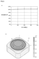
- Figure 5 is a diagram for explaining the relationship between the amount of displacement of the outermost lens 1 (translucent body) and the load.
- Figure 5(a) shows the change in the amount of displacement of the outermost lens 1 when weights of 0g to 800g are placed on the four corners of the housing 2. Note that the horizontal axis of Figure 5(a) shows the mass (g) of the weight, and the vertical axis shows the rate of change in the amount of displacement when the amount of displacement of the outermost lens 1 when a 0g weight is placed is 100%. When weights are placed on the four corners of the housing 2, the amount of displacement of the outermost lens 1 remains almost unchanged regardless of the mass of the weight.
- the displacement of the vibration device 10 is determined by simulation.
- the amount of displacement is indicated by the shade of hatching, with the darker hatching indicating the areas with the larger displacement.
- the outermost lens 1 has the largest displacement, at approximately 40 ⁇ m.
- the housing 2 has the smallest displacement, at approximately 0.8 ⁇ m.
- the displacement of the four corners of the housing 2 where the weight is placed is approximately 0.8 ⁇ m, which is approximately 2% of the maximum displacement of the outermost lens 1. Therefore, if the lightly hatched areas shown in FIG. 5(b) are 0.8 ⁇ m or less, the conditions for being able to hold the cover 7 are met. In other words, it is sufficient that the cover 7 is held in an area where the displacement is equal to or less than a predetermined value (for example, 2% of the maximum displacement).
- the cover portion 7 provides a gap between the leaf spring 2a and the retainer 2b where the displacement caused by the vibration of the vibrating body 3 is greater than a predetermined value (for example, 2% of the maximum displacement).
- the vibration device 10 provides intermediate members 71 and 72 to prevent foreign matter from entering this gap.
- the intermediate member 71 fills the gap between the cover portion 7 and the retainer 2b, and the intermediate member 72 fills the gap between the cover portion 7 and the leaf spring 2a. Therefore, the intermediate members 71 and 72 are in direct contact with the leaf spring 2a and the retainer 2b.
- the intermediate members 71 and 72 are in direct contact with the leaf spring 2a and the retainer 2b, they are made of a material with a small Young's modulus, such as rubber, resin, or sponge, that does not inhibit the vibration of the piezoelectric element 5 and does not reduce the vibration performance. It is preferable that the intermediate members 71 and 72 are not only functionally not to reduce the vibration performance, but also have functions such as waterproofness and sealing (caps can be formed).
- Figure 6 is a diagram for explaining the relationship between the displacement of the outermost lens 1 (translucent body) and the Young's modulus of the intermediate members 71 and 72.
- the horizontal axis of Figure 6 indicates the Young's modulus (GPa), and the vertical axis indicates the rate of change in the displacement when the displacement of the outermost lens 1 is 0% when the intermediate members 71 and 72 are not provided.
- the intermediate members 71 and 72 have a Young's modulus of 1.0 GPa or less, the displacement of the outermost lens 1 will be 0% even if the gap between the cover part 7 and the leaf spring 2a and the retainer 2b is filled with the intermediate members 71 and 72. Therefore, if the intermediate members 71 and 72 are made of a material with a Young's modulus of 1.0 GPa or less, the vibration of the piezoelectric element 5 will not be hindered and the vibration performance will not be reduced.
- Fig. 7 is a half cross-sectional view of a vibration device 10a according to a first modified example.
- the same components as those of the vibration device 10 shown in Fig. 2 are denoted by the same reference numerals, and the description thereof will not be repeated.
- the vibration device 10a is equipped with a cover part 7 that is held on the outer surface of the housing 2 with a gap provided so as not to come into direct contact with the leaf spring 2a. However, the vibration device 10a does not provide an intermediate member in the gap between the cover part 7 and the leaf spring 2a and the retainer 2b.
- the cover part 7 is positioned so as to cover the leaf spring 2a, so that at least it is possible to make it difficult for foreign matter to adhere to the leaf spring 2a.
- the vibration device 10a has a gap between the cover portion 7 and the retainer 2b, but the vibration device may have a configuration in which the gap between the cover portion 7 and the retainer 2b is filled.
- Fig. 8 is a half cross-sectional view of the vibration device 10b according to the modified example 2.
- the same components as those of the vibration device 10 shown in Fig. 2 are denoted by the same reference numerals, and the description thereof will not be repeated.
- the vibration device 10b has a cover part 7 that is held on the outer surface of the housing 2 with a gap provided so that it does not come into direct contact with the leaf spring 2a. Furthermore, the vibration device 10b has an intermediate member 71 provided in the gap between the cover part 7 and the retainer 2b. Therefore, the vibration device 10b can prevent foreign matter from entering the gap between the cover part 7 and the leaf spring 2a by using the intermediate member 71. Note that it is preferable to use a material with a Young's modulus of 1.0 GPa or less for the intermediate member 71, and furthermore, the intermediate member 71 is not limited to having one surface in contact with the leaf spring 2a as shown in FIG. 8, and it is not necessary that one surface of the intermediate member 71 is not in contact with the leaf spring 2a.
- the vibration device 10 has the cover portion 7 held on the side of the housing 2. However, if the cover portion 7 is held in a portion where the displacement is equal to or less than a predetermined value (for example, 2% of the maximum displacement amount), the vibration of the piezoelectric element 5 is not inhibited and the vibration performance is not deteriorated.
- Fig. 9 is a half cross-sectional view of a vibration device 10c according to a third modified example. Note that in the vibration device 10c, the same components as those of the vibration device 10 shown in Fig. 2 are denoted by the same reference numerals and will not be described repeatedly.
- the vibration device 10c is equipped with a cover part 7a that is held on the upper surface of the housing 2 (a surface parallel to the leaf spring 2a) with a gap provided so as not to come into direct contact with the leaf spring 2a.
- the portion where the cover part 7a is held is a portion where the displacement is equal to or less than a predetermined value, as shown in FIG. 4. Therefore, the cover part 7a covers the portion of the leaf spring 2a where the displacement is greater than the predetermined value, making it difficult for foreign matter to adhere to this portion.
- An intermediate member 71 may be provided in the gap between the cover part 7a and the retainer 2b.
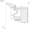
- Fig. 10 is a half cross-sectional view of a vibration device 10d according to a fourth modified example.
- the same components as those in the vibration device 10 shown in Fig. 2 are denoted by the same reference numerals, and the description thereof will not be repeated.
- the vibration device 10d is equipped with a cover portion 7b that is in direct contact with the leaf spring 2a.
- the cover portion 7b is made of a material with a Young's modulus of 1.0 GPa or less, because it is in direct contact with the portion of the leaf spring 2a where the displacement is greater than a predetermined value. Therefore, the vibration device 10d uses the cover portion 7b to prevent foreign matter from adhering to the leaf spring 2a, does not impede the vibration of the piezoelectric element 5, and does not degrade the vibration performance.
- the vibration device 10a has a cover portion 7 disposed substantially parallel to the leaf spring 2a. However, the vibration device may have a cover portion 7 inclined relative to the leaf spring 2a.
- Fig. 11 is a half cross-sectional view of a vibration device 10e according to a fifth modification. In the vibration device 10e, the same components as those of the vibration device 10 shown in Fig. 2 are denoted by the same reference numerals, and the description thereof will not be repeated.
- the vibration device 10e is equipped with a cover portion 7c that is held on the outer surface of the housing 2 with a gap provided so that it does not come into direct contact with the leaf spring 2a. Furthermore, the cover portion 7c is inclined from the outermost lens 1 side toward the side where it is held, and the position of the held cover portion 7c is lower than the position of the outermost lens 1 in the axial direction (Z direction) of the cylindrical body. By inclining the cover portion 7c in this manner, foreign matter W flows along the inner surface of the cover portion 7c (the surface facing the leaf spring 2a) as shown in FIG. 11, and the foreign matter W can be discharged from a discharge hole 73 provided in the cover portion 7c.
- the vibration device 10e is preferably attached to a device (e.g., a vehicle) so that the axial direction (Z direction) of the cylindrical body is approximately 90 degrees with respect to the direction of gravity G (downward in the figure) as shown in FIG. 11. Also, only the portion of the cover part 7c that is located on the lower side when attached to the device may be inclined. Furthermore, when adopting a configuration in which the cover part 7c is inclined, it is preferable to make the connection part 31 of the vibrating body 3 longer in the axial direction (Z direction) of the cylindrical body as shown in FIG. 11. Also, a water-repellent or hydrophilic coating material may be applied to the surface of the cover part 7c that faces the leaf spring 2a.
- a water-repellent or hydrophilic coating material may be applied to the surface of the cover part 7c that faces the leaf spring 2a.
- the vibration device 10e has a cover portion 7c inclined with respect to the leaf spring 2a to facilitate the discharge of foreign objects.
- the vibration device may have a guide portion for discharging foreign objects provided on the cover portion to facilitate the discharge of foreign objects.
- Fig. 12 is a half cross-sectional view of a vibration device 10f according to a sixth modified example.
- the same components as those of the vibration device 10 shown in Fig. 2 are denoted by the same reference numerals, and the description thereof will not be repeated.
- the vibration device 10f includes a cover portion 7d that is held on the outer surface of the housing 2 with a gap provided so as not to come into direct contact with the leaf spring 2a. Furthermore, the cover portion 7d has an uneven surface facing the leaf spring 2a and is provided with a guide portion 74 for discharging foreign matter. By providing the guide portion 74 on the cover portion 7d in this manner, the foreign matter W flows along the guide portion 74 as shown in FIG. 12, and can be discharged from a discharge hole 73 provided in the cover portion 7d.
- the vibration device 10f is preferably attached to a device (e.g., a vehicle) so that the axial direction (Z direction) of the cylindrical body is at approximately 90 degrees with respect to the direction of gravity G (downward in the figure) as shown in FIG. 12.
- the cover part 7d may be provided with a guide part 74 only on the part that will be located on the lower side when attached to the device.
- the cover part 7d may be inclined like the cover part 7c shown in FIG. 11.
- a water-repellent or hydrophilic coating material may be applied to the surface of the cover part 7d that faces the leaf spring 2a.
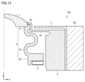
- FIG. 13 is a diagram for explaining the mounting position of the cover part 7.
- the cover part 7 is held on the vehicle body 90 with a gap provided so that it does not come into direct contact with the leaf spring 2a.
- the vehicle body 90 is part of the device to which the vibration device 10a is attached.
- the cover part 7 can be held in a part where the vibration of the vibration device 10a is not propagated.
- the cover part 7 is held between the housing 2 and the vehicle body 90.
- the cover part 7 is not limited to being held between the housing 2 and the vehicle body 90, but may be held only by the vehicle body.
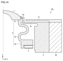
- Figure 14 is a diagram for explaining different mounting positions of the cover part. As shown in Figure 14, the cover part 7e is held by the vehicle body 90 with a gap provided so that it does not come into direct contact with the leaf spring 2a. The housing 2 and the vehicle body 90 are directly connected, and the cover part 7e is held only by the vehicle body 90.
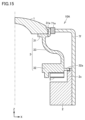
- FIG. 15 is a half cross-sectional view of the vibration device 10A according to the second embodiment. Note that in the vibration device 10A, the same components as those in the vibration device 10 shown in FIG. 2 are denoted by the same reference numerals, and the description thereof will not be repeated. Moreover, the vibration device 10A can be combined with a sensor device 20 instead of the vibration device 10 shown in FIG. 1 to form an imaging device 100.
- the vibrating body 3 is a cylindrical body and is composed of a connection part 31 (first part) that contacts the outermost lens 1, a vibration part 32 (second part) that has a piezoelectric element 5, and a support part 33 (third part) that connects the connection part 31 and the vibration part 32.
- connection part 31 is a cylindrical part that contacts the bottom surface of the outermost lens 1, and transmits the vibration of the vibrating body 3 to the outermost lens 1. It has a holding part 31a to stably hold the outermost lens 1 in the radial direction (X and Y directions) of the cylindrical body.
- the connection part 31 and the holding part 31a may be formed integrally, or may be formed separately and then combined.
- the vibration part 32 is a part that vibrates with the vibration of the piezoelectric element 5, and has a thickness greater than the thicknesses of the connection part 31 and the support part 33.
- the vibration part 32 has a flange 32a (extension part) that extends outward on the side surface thereof.
- the flange 32a is supported by the support part 2c of the housing 2.
- the flange 32a and the support part 2c are joined together, for example, with an adhesive.
- the hollow circular piezoelectric element 5 vibrates in the radial direction, and this vibration is converted by the support part 33 of the vibrating body 3 into vibration in the Z direction (the up and down direction in the figure), causing the outermost lens 1 to vibrate in the Z direction.
- FIG. 16 is a schematic diagram for explaining the displacement that occurs in the vibration device 10A according to the second embodiment.
- the vibration body 3 causes the support portion 33 to elastically deform like a spring, thereby displacing the outermost lens 1 significantly in the Z direction.
- the connection portion 31, the holding portion 31a, the vibration portion 32, and the support portion 33 of the vibration body 3 are also significantly displaced. Note that in FIG. 16, the magnitude of displacement is indicated by the shade of hatching, with darker hatching indicating areas with greater displacement, with the outermost lens 1 having the greatest displacement. Meanwhile, the housing 2 has the smallest displacement.
- a cover portion 7f is provided to cover the vibrating body 3 to prevent foreign matter from adhering to the vibrating body 3.
- the cover portion 7f is supported on the outer surface of the housing 2 (the surface perpendicular to the flange 32a) with a gap provided so that it does not come into direct contact with the vibrating body 3. Therefore, the cover portion 7f itself is not displaced by the vibration of the vibrating body 3, so foreign matter does not remain on the surface of the cover portion 7f, and there is no risk of the vibration of the piezoelectric element 5 being hindered by the attached foreign matter, resulting in a decrease in vibration performance. It is sufficient for the cover portion 7f to be able to cover the vibrating body 3, including at least a portion of the flange 32a whose displacement is greater than a predetermined value (for example, 2% of the maximum displacement).
- the cover portion 7f has a gap between it and the holding portion 31a where the displacement caused by the vibration of the vibrating body 3 is greater than a predetermined value.
- the vibration device 10A has an intermediate member 71a to prevent foreign matter from entering this gap.
- the intermediate member 71a fills the gap between the cover portion 7f and the holding portion 31a. Therefore, the intermediate member 71a comes into direct contact with the holding portion 31a.
- the intermediate member 71a is made of a material with a small Young's modulus such as rubber, resin, or sponge (for example, a material with a Young's modulus of 1 GPa or less) so as not to inhibit the vibration of the piezoelectric element 5 or to reduce vibration performance.
- the intermediate member 71a is preferably a material that not only has the function of not reducing vibration performance, but also has functions such as waterproofing and sealing (can be covered).
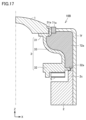
- Fig. 17 is a half cross-sectional view of a vibration device 10B according to a modified example of embodiment 2. Note that in vibration device 10B, the same components as those in vibration device 10A shown in Fig. 15 are denoted by the same reference numerals, and description thereof will not be repeated.
- a cover portion 7f is provided to cover vibrating body 3 to prevent foreign matter from adhering to vibrating body 3.
- Cover portion 7f is held on the outer surface of housing 2 with a gap so that it does not come into direct contact with vibrating body 3.
- Vibrating device 10B has intermediate members 71a and 72a to prevent foreign matter from entering this gap.
- Intermediate member 71a fills the gap between cover portion 7f and holding portion 31a
- intermediate member 72a fills the gap between cover portion 7f and vibrating body 3. Therefore, intermediate members 71a and 72a are in direct contact with vibrating body 3.
- intermediate members 71a and 72a use materials with a small Young's modulus such as rubber, resin, and sponge (for example, a material with a Young's modulus of 1 GPa or less) so as not to inhibit the vibration of piezoelectric element 5 and not to deteriorate vibration performance.
- the intermediate members 71a and 72a are members that not only have the function of not reducing vibration performance, but also have functions such as waterproofing and sealing (the ability to form a lid).
- the gap between the leaf spring 2a and the cover part 7 and the retainer 2b is filled with intermediate members 71 and 72 to prevent foreign matter from entering the gap.
- the intermediate member 71 fills the gap between the retainer 2b (extension side) and the cover part 7, and the intermediate member 72 fills the gap between the leaf spring 2a (extension) and the cover part 7.
- the shape of the intermediate member in contact with the cover part 7 also affects the vibration performance of the vibrating body 3. Therefore, in the third embodiment, the shape of the intermediate member in contact with the cover part 7 is further examined.
- FIG. 18 is a half cross-sectional view of vibration device 10 according to embodiment 3.
- Vibration device 10 shown in FIG. 18 has the same configuration as vibration device 10 shown in FIG. 2, and the same components are given the same reference numerals and detailed description will not be repeated.
- intermediate member 71 sandwiched between retainer 2b and cover portion 7 is considered to have a greater impact on the vibration performance of vibrating body 3 than intermediate member 72, as shown in FIG. 18. Therefore, the relationship between the amount of displacement of outermost lens 1 and the shape of intermediate member 71 will be examined.
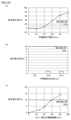
- FIG. 19 is a diagram for explaining the relationship between the amount of displacement of outermost lens 1 and the dimensions of intermediate member 71.
- the intermediate member 71 has a thickness t (length in the X direction), a width w (length in the Z direction), and a contact area S with the cover portion 7.
- the thickness t corresponds to the length of the extension direction (length in the X direction) of the leaf spring 2a (extension portion).
- the contact area S can be calculated by multiplying the inner circumference of the cover portion 7 by the thickness k of the cover portion 7.
- FIG. 19(a) shows the rate of change in the amount of displacement of the outermost lens 1 when the thickness t of the intermediate member 71 is changed.
- FIG. 19(a) shows the thickness t (mm) of the intermediate member 71, and the vertical axis shows the rate of change in the amount of displacement when the amount of displacement of the outermost lens 1 is 0% when the cover portion 7 is not provided.
- the width w of the intermediate member 71 is fixed to 2 mm as a prerequisite.
- Figure 19(b) shows the rate of change in the amount of displacement of the outermost lens 1 when the thickness w of the intermediate member 71 is changed.
- the horizontal axis of Figure 19(b) shows the thickness w (mm) of the intermediate member 71
- the vertical axis shows the rate of change in the amount of displacement when the amount of displacement of the outermost lens 1 is 0% when no cover portion 7 is provided.
- the thickness t of the intermediate member 71 is fixed at 0.4 mm as a prerequisite. As shown in Figure 19(b), even if the thickness w of the intermediate member 71 is changed to 1 mm and then 2 mm, there is almost no effect on the rate of change in the amount of displacement. In other words, it can be seen that the thickness w of the intermediate member 71 does not affect the vibration performance of the vibrating body 3.
- FIG. 19(c) shows the rate of change in the amount of displacement of the outermost lens 1 when the contact area S of the intermediate member 71 with the cover portion 7 is changed.
- the horizontal axis of FIG. 19(c) shows the contact area S ( mm2 ) with the cover portion 7, and the vertical axis shows the rate of change in the amount of displacement when the amount of displacement of the outermost lens 1 with the cover portion 7 is 0%.
- the thickness t of the intermediate member 71 is fixed to 0.4 mm and the width w is fixed to 2 mm as a prerequisite. As shown in FIG.
- the intermediate members 71 and 72 may be made of a material, for example, foamed with polypropylene (PP) as the main component, and may be made of a material with a Young's modulus of 1.0 GPa or less or a material with a Young's modulus of more than 1.0 GPa.
- PP polypropylene
- FIG. 20 is a half cross-sectional view of a vibration device 10C according to a modified example of embodiment 3.
- the vibration device 10C shown in Figure 20 the same components as those of the vibration device 10 shown in Figure 2 are assigned the same reference numerals and detailed description will not be repeated.
- the outermost lens 1 protrudes in the Z direction compared to the vibration device 10 shown in FIG. 2, and has a cylindrical shape.
- the leaf spring 2a extending in the X direction is bent in the Z direction near the vibration body 3, and the connection part 31 of the vibration body 3 and the retainer 2b are connected, so that the outermost lens 1 has a cylindrical shape protruding in the Z direction.
- the cover part 7 is in contact with the retainer 2b through the intermediate member 71.
- the intermediate member 71 has a thickness t of 0.4 mm or less and a contact area S with the cover part 7 of 60 mm 2 or less.
- the thickness w (length in the Z direction) of the intermediate member 71 it can be provided long along the retainer 2b.
- Fig. 21 is a half cross-sectional view of the vibration device 10D according to the fourth embodiment.
- the same components as those in the vibration device 10 shown in Fig. 2 are denoted by the same reference numerals and detailed description will not be repeated.
- vibration device 10D As shown in FIG. 21, a part of housing 2 to which vibrations of vibration device 10D are not propagated is connected to vehicle body 91, and part of vehicle body 91 contacts leaf spring 2a and retainer 2b via intermediate members 71, 72. In other words, part of vehicle body 91 functions as cover part 7 shown in FIG. 2. Therefore, vibration device 10D can be structured without a cover part. Note that the vibration frequency of vehicle body 91 when the vehicle is running is about 1 to 100 Hz, and even if vibrations are transmitted to vibration device 10D via a part of vehicle body 91 functioning as a cover part, this is significantly different from the resonant frequency of vibration device 10D and does not affect vibration performance.
- Fig. 22 is a perspective view of a vibration device 10E according to the fifth embodiment.
- the same components as those in the vibration device 10 shown in Fig. 1 are denoted by the same reference numerals and detailed description will not be repeated.
- the cover portion 701 is attached to the housing 2 as shown in FIG. 22(a).
- the cover portion 701 has claw portions 701a at two opposing corners.
- the housing 2 has stopper portions 201 at positions corresponding to the claw portions 701a. Therefore, the cover portion 701 can be attached to the housing 2 by fitting the claw portions 701a into the stopper portions 201.
- the number and positions of the claw portions 701a provided on the cover portion 701 are not limited to those shown in FIG. 22(a).
- the number and positions of the stopper portions 201 provided on the housing 2 correspond to the number and positions of the claw portions 701a provided on the cover portion 701.
- FIG. 22(b) shows a cover part 702 provided with press-fit protrusions 702a instead of claws.
- the cover part 702 has protrusions 702a at its four corners.
- the housing 2 has insertion parts at positions corresponding to the protrusions 702a. Note that the number and positions of the protrusions 702a on the cover part 702 are not limited to those shown in FIG. 22(b). The number and positions of the insertion parts on the housing 2 correspond to the number and positions of the protrusions 702a on the cover part 702.
- the cover can be attached to the housing (the cover can be fixed to the vibration device) using the claws 701a, stopper 201, and press-fit protrusions 702a, as well as mechanical fixing methods such as screws.
- the cover can also be attached to the housing using an adhesive.
- the cross-sectional shape of the support portion 33 is described as being S-shaped, but the cross-sectional shape of the support portion is not limited to an S-shape as long as the shape does not cause stress concentration in the vibrating body.
- the cross-sectional shape of the support portion 33 may be, for example, a shape formed by connecting multiple S-shapes, or a curved shape that is half an S-shape.
- the imaging device may include a camera, LiDAR, radar, etc. Also, multiple imaging devices may be arranged side by side.
- the imaging device is not limited to an imaging device installed in a vehicle, but can be similarly applied to any imaging device that includes an optical device and an imaging element arranged so that the light-transmitting body is in the field of view, and that requires the removal of foreign objects from the light-transmitting body.
- the vibration device is A light-transmitting body that transmits light of a predetermined wavelength; a vibrator that contacts the transparent body and vibrates the transparent body; A piezoelectric element provided on a vibrating body; an extension portion extending outward from a side wall of the vibrating body which is a cylindrical body; and a cover portion that covers at least a portion of the extension portion and the vibrating body.
- the vibration device does not degrade vibration performance by providing a cover section to prevent foreign matter from adhering to at least a portion of the extension section and the vibrating body.
- the cover portion is held in place by providing a gap between the vibrating body and the portion of the extension portion where the displacement due to the vibration of the vibrating body is greater than a predetermined value, and at or below the predetermined value.
- the vibration device described in (2) further includes an intermediate member disposed in the gap between the vibrating body or the extension portion and the cover portion and having a Young's modulus of 1 GPa or less.
- the vibration device described in (2) further includes an intermediate member disposed in the gap between the vibrating body or the extension portion and the cover portion, the intermediate member having a length of 0.4 mm or less in the extension direction of the extension portion.
- the vibration device according to (2) further includes an intermediate member disposed in a gap between the vibrating body or the extension and the cover, the intermediate member having a contact area with the cover of 60 mm2 or less .
- the cover is inclined from the light-transmitting body side toward the side where the cover is held, The position of the held cover portion is lower than the position of the light-transmitting body in the axial direction of the cylindrical body.
- the cover portion has an uneven surface facing the vibrating body or the extension portion, and has a guide portion that discharges foreign matter.
- the cover portion has a water-repellent or hydrophilic coating applied to the surface facing the vibrating body or the extension portion.
- the cover portion is held by a part of the device to which the vibration device is attached.
- the cover portion is a part of the device to which the vibration device is attached.
- the cover is attached to the vibration device by a mechanical fastening method or a fastening method using an adhesive.
- the cover portion is in contact with at least the portion of the vibrating body and the extension portion where the displacement due to vibration of the vibrating body is greater than a predetermined value, and is formed of a material with a Young's modulus of 1 GPa or less.
- An imaging device A vibration device according to any one of (1) to (12), and an imaging element arranged so that the light-transmitting body is in the field of view.
Landscapes
- Physics & Mathematics (AREA)
- General Physics & Mathematics (AREA)
- Electromagnetism (AREA)
- Engineering & Computer Science (AREA)
- Multimedia (AREA)
- Signal Processing (AREA)
- Camera Bodies And Camera Details Or Accessories (AREA)
Priority Applications (3)
| Application Number | Priority Date | Filing Date | Title |
|---|---|---|---|
| DE112024002497.1T DE112024002497T5 (de) | 2023-08-07 | 2024-05-07 | Schwingvorrichtung und bilderzeugungsgerät |
| JP2025539129A JPWO2025032897A1 (https=) | 2023-08-07 | 2024-05-07 | |
| CN202480050139.9A CN121666758A (zh) | 2023-08-07 | 2024-05-07 | 振动装置和摄像装置 |
Applications Claiming Priority (2)
| Application Number | Priority Date | Filing Date | Title |
|---|---|---|---|
| JP2023-128571 | 2023-08-07 | ||
| JP2023128571 | 2023-08-07 |
Publications (1)
| Publication Number | Publication Date |
|---|---|
| WO2025032897A1 true WO2025032897A1 (ja) | 2025-02-13 |
Family
ID=94533895
Family Applications (1)
| Application Number | Title | Priority Date | Filing Date |
|---|---|---|---|
| PCT/JP2024/016934 Pending WO2025032897A1 (ja) | 2023-08-07 | 2024-05-07 | 振動装置、および撮像装置 |
Country Status (4)
| Country | Link |
|---|---|
| JP (1) | JPWO2025032897A1 (https=) |
| CN (1) | CN121666758A (https=) |
| DE (1) | DE112024002497T5 (https=) |
| WO (1) | WO2025032897A1 (https=) |
Citations (2)
| Publication number | Priority date | Publication date | Assignee | Title |
|---|---|---|---|---|
| JP2017170303A (ja) * | 2016-03-22 | 2017-09-28 | オリンパス株式会社 | 液滴排除装置と、液滴排除装置を有する画像装置及び上記液滴排除装置の制御方法と上記液滴排除装置の制御プログラム |
| WO2023127197A1 (ja) * | 2021-12-28 | 2023-07-06 | 株式会社村田製作所 | 振動装置及び撮像装置 |
-
2024
- 2024-05-07 JP JP2025539129A patent/JPWO2025032897A1/ja active Pending
- 2024-05-07 DE DE112024002497.1T patent/DE112024002497T5/de active Pending
- 2024-05-07 WO PCT/JP2024/016934 patent/WO2025032897A1/ja active Pending
- 2024-05-07 CN CN202480050139.9A patent/CN121666758A/zh active Pending
Patent Citations (2)
| Publication number | Priority date | Publication date | Assignee | Title |
|---|---|---|---|---|
| JP2017170303A (ja) * | 2016-03-22 | 2017-09-28 | オリンパス株式会社 | 液滴排除装置と、液滴排除装置を有する画像装置及び上記液滴排除装置の制御方法と上記液滴排除装置の制御プログラム |
| WO2023127197A1 (ja) * | 2021-12-28 | 2023-07-06 | 株式会社村田製作所 | 振動装置及び撮像装置 |
Also Published As
| Publication number | Publication date |
|---|---|
| CN121666758A (zh) | 2026-03-13 |
| DE112024002497T5 (de) | 2026-05-07 |
| JPWO2025032897A1 (https=) | 2025-02-13 |
Similar Documents
| Publication | Publication Date | Title |
|---|---|---|
| CN114829213B (zh) | 振动装置和振动控制方法 | |
| US11369996B2 (en) | Vibration device and imaging unit including vibration device | |
| JP6819844B1 (ja) | 振動装置、および振動装置を備える撮像ユニット | |
| JP7111258B2 (ja) | 振動装置及び振動制御方法 | |
| CN113168076B (zh) | 振动装置和具备振动装置的摄像单元 | |
| WO2021100232A1 (ja) | 振動装置、および振動装置を備える撮像ユニット | |
| US11383274B2 (en) | Vibration device and imaging unit including vibration device | |
| WO2021002056A1 (ja) | 光学ユニット、および光学ユニットが搭載された車両 | |
| US20250328008A1 (en) | Imaging unit | |
| WO2021038942A1 (ja) | 振動装置及び光学検出装置 | |
| WO2025032897A1 (ja) | 振動装置、および撮像装置 | |
| US20240288685A1 (en) | Optical module and optical device | |
| WO2023210101A1 (ja) | 光学装置、および光学装置を備える撮像ユニット | |
| WO2026062949A1 (ja) | 振動装置、および撮像装置 | |
| US20250355320A1 (en) | Optical device and imaging unit including optical device | |
| WO2025150230A1 (ja) | 撮像装置 | |
| WO2025027965A1 (ja) | 振動装置、および撮像装置 | |
| WO2025248827A1 (ja) | 振動装置、および撮像装置 | |
| US20240280803A1 (en) | Optical module and optical device | |
| US20240353677A1 (en) | Optical device and imaging unit including optical device | |
| JP7776020B2 (ja) | 光学装置、および光学装置を備える撮像ユニット | |
| WO2026069811A1 (ja) | 振動装置、および撮像装置 | |
| CN118382834A (zh) | 光学模块和光学装置 | |
| WO2020137262A1 (ja) | 振動装置及び光学検出装置 | |
| JP2009278401A (ja) | 光学部品及び光学機器 |
Legal Events
| Date | Code | Title | Description |
|---|---|---|---|
| 121 | Ep: the epo has been informed by wipo that ep was designated in this application |
Ref document number: 24851331 Country of ref document: EP Kind code of ref document: A1 |
|
| ENP | Entry into the national phase |
Ref document number: 2025539129 Country of ref document: JP Kind code of ref document: A |
|
| WWE | Wipo information: entry into national phase |
Ref document number: 2025539129 Country of ref document: JP |