WO2025032657A1 - 細隙灯顕微鏡システム、プログラム、プログラムを記録したコンピュータ読み取り可能な記録媒体及び細隙灯顕微鏡システムの作動方法 - Google Patents
細隙灯顕微鏡システム、プログラム、プログラムを記録したコンピュータ読み取り可能な記録媒体及び細隙灯顕微鏡システムの作動方法 Download PDFInfo
- Publication number
- WO2025032657A1 WO2025032657A1 PCT/JP2023/028635 JP2023028635W WO2025032657A1 WO 2025032657 A1 WO2025032657 A1 WO 2025032657A1 JP 2023028635 W JP2023028635 W JP 2023028635W WO 2025032657 A1 WO2025032657 A1 WO 2025032657A1
- Authority
- WO
- WIPO (PCT)
- Prior art keywords
- eye
- image
- unit
- images
- microscope system
- Prior art date
- Legal status (The legal status is an assumption and is not a legal conclusion. Google has not performed a legal analysis and makes no representation as to the accuracy of the status listed.)
- Pending
Links
Images



Classifications
-
- A—HUMAN NECESSITIES
- A61—MEDICAL OR VETERINARY SCIENCE; HYGIENE
- A61B—DIAGNOSIS; SURGERY; IDENTIFICATION
- A61B3/00—Apparatus for testing the eyes; Instruments for examining the eyes
- A61B3/10—Objective types, i.e. instruments for examining the eyes independent of the patients' perceptions or reactions
- A61B3/13—Ophthalmic microscopes
- A61B3/135—Slit-lamp microscopes
Definitions
- the technology described in this specification relates to a slit lamp microscope system, a program, a computer-readable recording medium having the program recorded thereon, and a method for operating the slit lamp microscope system.
- eye examination methods involve shining a slit lamp (slit light) onto the anterior segment of the eye and scanning it for observation.
- Ophthalmologists use tabletop binocular slit lamp microscopes to observe and capture cross-sections of the eyeball to diagnose the condition of the eye.
- Conventional slit lamp microscopes require precise and complex optical systems, and are therefore large and expensive.
- imaging devices have been proposed that can be attached to mobile terminals to easily capture images of the anterior segment of the eye.
- Patent Document 1 discloses a close-up photography device that is detachably attached to a mobile terminal equipped with a light source and a camera lens for photographing, and that switches the path of light from the light source to observe and photograph the anterior segment and fundus.
- the close-up photography device further includes a member for forming slit light, and further includes a slit forming member for converting diffuse light irradiated onto the anterior segment from the light source of the mobile terminal into slit light, and the light reflected from the anterior segment enters the camera lens for photographing of the mobile terminal, and is photographed and saved by an internal application.
- Patent Document 1 The close-up photography device in Patent Document 1 is simple, but it is difficult to obtain uniform images because the photography conditions vary depending on the photographer and the type of mobile terminal to which it is attached. Also, as with conventional examinations using slit lamp microscopes, a specialist doctor's examination is required to determine the condition of the eye from the captured images.
- AI artificial intelligence
- AI artificial intelligence
- the technology described in this specification aims to obtain eye images suitable for AI analysis by using inexpensive, simple imaging equipment, and to use AI to quickly and accurately analyze the images and determine the condition of the eye.
- the slit lamp microscope system includes an imaging unit that scans the eye with a slit light, an analysis unit that uses AI to analyze the images acquired by the imaging unit, and a judgment unit that judges the condition of the eye from the results of the analysis by the analysis unit, and the imaging unit takes multiple images at each predetermined angle when scanning.
- images of the eye suitable for AI analysis can be obtained using inexpensive, simple imaging equipment, and the images can be analyzed quickly and accurately using AI to determine the condition of the eye.
- FIG. 1 is a block diagram showing the configuration of a slit lamp microscope system according to an embodiment.
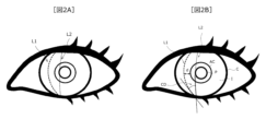
- FIG. 2A is a diagram showing a schematic image of a slit light beam irradiating an eyeball
- FIG. 2B is a diagram for explaining the structure of the eye.
- FIG. 3 is a diagram for explaining the process in which the analysis unit extracts features from an image obtained by taking the average value of a plurality of images using LWBNA_UNet.
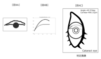
- 4A and 4B are diagrams for explaining the process of the determination unit calculating various parameters, in which Fig. 4A is an average value image, Fig. 4B is a graph plotting the boundaries of the cornea and the iris, and Fig. 4C is an image in which the eye condition is determined.
- a slit lamp microscope system an imaging device, a processing device, a program, a computer-readable recording medium having the program recorded thereon, and a method of operating the slit lamp microscope system as embodiments will be described.
- the embodiments described below are merely examples, and are not intended to exclude the application of various modifications or techniques not explicitly stated in the following embodiments.
- Each configuration of the embodiments can be modified in various ways without departing from the spirit thereof. Furthermore, they can be selected or combined as necessary.
- the directions in FIG. 1 used in the explanation are defined as follows: the horizontal direction is the front-to-rear direction (in the figure, the front is indicated by “F” and the rear is indicated by “B"), and the vertical direction in which gravity acts is defined as downward (indicated by “D” in the figure), and the opposite direction of downward is defined as upward (indicated by "U” in the figure).
- FIG. 1 is a block diagram showing the configuration of a slit lamp microscope system 1 according to an embodiment.
- the slit lamp microscope system 1 according to this embodiment is composed of an imaging device 10 and a processing device 20.
- the imaging device 10 scans an eye with slit light, and captures multiple images at each predetermined angle during the scan.
- the processing device 20 processes the images acquired by the imaging device 10. Details of each function will be described later.
- the processing device 20 may be built-in (mounted) or integrated into the imaging device 10, or may be provided separately from the imaging device 10. When the processing device 20 is provided separately from the imaging device 10, the imaging device 10 and the processing device 20 may be connected wirelessly or by wire, and the imaging device 10 may be remotely operated.
- the slit lamp microscope system 1 may further be connected to an output device 30.
- the output device 30 displays the images acquired by the imaging device 10, as well as the analysis results and judgment results acquired by the processing device 20.
- the slit lamp microscope system 1 and the output device 30 may be connected by wire or wirelessly.
- a slit lamp microscope system 1 in which the imaging device 10 and processing device 20 are integrated is described as an example, and is connected to an output device 30.
- the imaging device 10 is composed of an illumination system that scans a human eye with slit light, and an imaging system that captures multiple images at each predetermined angle when scanning.
- the imaging device 10 is provided with a hole that is placed in front of the subject's eye. By aligning the hole with the eye so as to cover the eye, it is possible to irradiate the eye with slit light and capture an image. By aligning the hole with the eye, the distance between the eye and the imaging device 10 is maintained constant.
- the imaging device 10 may capture images of eyes other than humans, and may capture images of the eyes of various animals such as dogs and cats.
- the illumination system includes a light source 10a, a pinhole 10b, a convex lens 10c, a guide mirror 10d, a slit mechanism 10e, and a scan mirror 10h.
- a white LED light emitting diode
- Visible light is used as the light, but infrared light (near-infrared light) may also be used.
- the light intensity is such that the subject does not feel uncomfortable with their eyes open. As an example, the light intensity is 1000 nW to 500 nW or less. In the present invention, even if the light is very weak and does not cause discomfort to the subject, a data set that can be analyzed by AI can be obtained by using the system of the present invention.
- the amount of light irradiated from the light source 10a is adjusted by the pinhole 10b and focused by the convex lens 10c.
- the light focused by the convex lens 10c is reflected by the guide mirror 10d and enters the slit mechanism 10e.
- the slit mechanism 10e is composed of, for example, a mechanical slit 10f and a cylindrical lens 10g, and forms a slit beam.
- the light reflected by the guide mirror 10d passes through the slit 10f and the cylindrical lens 10g, and a line of light (slit beam) of a desired size is formed.
- the slit beam of a desired size is, for example, a long and narrow rectangular beam, preferably 100 to 500 ⁇ m in width and 2 to 3 mm in length.
- the slit light is not limited to the slit mechanism 10e composed of the mechanical slit 10f and the cylindrical lens 10g, but may have another configuration.
- the slit light may be created by using only the mechanical slit 10f and a magnifying lens for the light that passes through the slit 10f.
- the slit light may be created by using only the cylindrical lens 10g without using the mechanical slit 10f.
- the slit light emitted from the slit mechanism 10e is reflected by the scan mirror 10h and irradiated onto the anterior segment of the eye.
- the scan mirror 10h has a motor 10j, and its angle changes according to the rotation of the motor 10j.
- the incidence angle and position of the slit light L that strikes the anterior segment of the eye (hereinafter, the anterior segment may be simply referred to as the eye) changes.
- the angle of the scan mirror 10h is controlled so that the slit light strikes the eye at an angle of 30° to 45°.
- the imaging system includes an imaging means (camera) 10i.
- the imaging means 10i has a motor 10k, as well as a lens and an imaging element (not shown).
- the angle of the imaging means 10i changes according to the rotation of the motor 10k.
- the imaging position changes by controlling the rotation of the motor 10k.
- a slit of light When a slit of light is shone obliquely onto the anterior segment of the eye, the light traveling inside the eye forms a bright line on the surface of the anterior segment. For example, if a slit of light is shone onto the eye from the left diagonal front, the light strikes the cornea, iris, lens, and vitreous body from the left, causing streaks of light to appear at each point. The slit of light reflected by the eye passes through the lens of the imaging means 10i and is received by the imaging element. In this way, an image of the test eye is taken.
- the imaging device 10 transmits the acquired images to the processing device 20 via wired or wireless communication during or after the inspection.
- the imaging device 10 may store the acquired images in an internal memory.
- Motors 10j and 10k are realized, for example, by servo motors. More preferably, they are realized by step motors, which can control the rotation angle more precisely and finely than servo motors.
- the rotation angle of motors 10j and 10k is selected to be an angle suitable for scanning and imaging the entire anterior segment.
- the scan mirror 10h of the imaging unit 10 scans the eye with slit light.
- the initial angle of the scan mirror 10h is set to 20° in the front-rear direction, for example.
- the initial angle is set in advance so that the slit light hits the eye according to the shape of the imaging unit 10. This initial setting allows the slit light to hit one end of the eye. Since the average diameter of the cornea of the eye is about 12 mm, a scan distance of at least 12 mm is required to scan the entire eye, including areas other than the cornea. Therefore, it is preferable to set the total scan distance to 15 mm to 25 mm. As an example, the total scan distance is set to 20 mm.
- the angle of the motor 10j that moves the scan mirror 10h is set from an initial angle of 20° to a final angle of 32°, so that the entire cornea of the eye can be reliably scanned.
- the scan mirror 10h irradiates the eye with the slit light vertically or horizontally depending on the information required for judging the eye state.
- the slit light may be irradiated horizontally to the eye by rotating the imaging unit 10 90° to the left or right.
- the imaging unit 10 changes the angle of the scan mirror 10h continuously or discretely, moving the slit light from one end of one eye to the other end (the left and right ends, or the top and bottom ends), and then from the other end to one end.
- scanning is performed by moving the slit light back and forth between one end and the other end of one eye.
- One round-trip scan takes approximately 30 seconds.
- scanning may also be performed by moving the slit light only one way between one end and the other end of one eye.
- the imaging means 10i moves in sync with the scan mirror 10h. Furthermore, the scan mirror 10h and the imaging means 10i stop at each predetermined angle when scanning the eye. This is achieved by controlling the motors 10j and 10k described above.
- the predetermined angle can be selected from any range of angles (e.g., 0.2° to 3°) in the vertical and horizontal directions relative to the eye. For example, if the predetermined angle is 1°, the eye can be scanned at a distance of 1.67 mm.
- the imaging means 10i captures multiple images for each predetermined angle at which the scan mirror 10h stops while scanning. "Multiple images” means any number of frames.
- All components of the imaging device 10 may be controlled by a processing device 20 described below, or may be controlled by a control device (IC board, not shown) provided within the imaging device 10.
- the processing unit 20 processes the image acquired by the imaging unit 10.
- the processing unit 20 has at least an analysis unit 21 that analyzes the image acquired by the imaging unit 10 using AI (Artificial Intelligence), and a judgment unit 22 that judges the state of the eye from the analysis result of the analysis unit 21.
- the processing unit 20 further has an output unit 23 that outputs the acquired image, analysis result, and judgment result to the output device 30, and a storage unit 24 that stores various data.
- each of these elements may be realized by an electronic circuit (hardware), or some of these functions may be provided as hardware and the other parts may be software.
- the analysis unit 21 creates an image by taking the average value from the images acquired by the imaging unit 10, and analyzes the image using AI.
- the process of taking the average value of the image is a preprocessing step for using the image of the anterior eye illuminated with slit light in AI analysis.
- the challenge is that the intensity of the slit light reflected from the eye (particularly the cornea and lens) or diffused inside the eye is weak due to the transparent nature of the cornea and lens.
- it is necessary to record images and videos in a darker place, which causes significant discomfort to the patient. Reducing the intensity of the slit light reduces the subject's discomfort, but makes it difficult to detect the slit light reflected from the cornea and lens.
- images and videos captured in a dark place with reduced intensity of the slit light tend to be very noisy, making it very difficult to obtain images for AI analysis. Thus, there is a trade-off between image quality and the subject's discomfort.
- the inventors have therefore discovered a method that satisfies both image quality and subject comfort. With this method, even when a low-intensity slit light is used, the reflected slit light is captured at a predetermined angle and multiple images are selected, and the imaging means 10i detects in synchronization with the scan mirror 10h, making it possible to obtain a high-quality image that includes a clearly visible cornea and crystalline lens.
- the method for creating an image for AI analysis is described below.
- the analysis unit 21 acquires images captured by the imaging unit 10 at each predetermined angle.
- the analysis unit 21 discards images that do not include the image of the desired eye among the entire images captured at each predetermined angle, and discards images that do not include the image of the desired eye among the images captured at each predetermined angle (for example, about 20 images).
- the image of the desired eye is an image in which the eye is clearly captured.
- the first few images (for example, 1 to 3 frames) of the multiple images captured at each predetermined angle are often blurred because they are captured immediately after the operation (motor rotation) of the scan mirror 10h and the imaging means 10i has stopped. For this reason, the analysis unit 21 discards the first few images of the multiple images acquired from the imaging unit.
- the analysis unit 21 may select images by overlaying a drawing image described below onto multiple images acquired from the imaging unit, or may use only images that are above a predetermined threshold value for analysis.
- the analysis unit 21 then creates an image (average image) by averaging the images that were not discarded from among the multiple captured images. By averaging the multiple images that were not discarded, it is possible to obtain an image in which the cornea and crystalline lens are clearly visible even when the intensity of the slit light is weak.
- FIG. 2A is a schematic diagram showing an image of slit light illuminating an eyeball.
- slit light is irradiated from the right front diagonally onto the right eye.
- the average value image shows the anterior segment of the eye, slit light L1 passing through (reflected by) the cornea C, and slit light L2 passing through (reflected by) the iris I.
- slit light L1 will be referred to as corneal reflected slit light L1
- slit light L2 will be referred to as iris reflected slit light L2.
- the analysis unit 21 obtains one average image from multiple images captured at each predetermined angle.
- the analysis unit 21 performs the process of scanning the eye and simultaneously capturing images from one end of one eye to the other at each predetermined angle, so that multiple average images (for the number of times the image was stopped at each predetermined angle) are created for each eye in one scan (a predetermined range, for example, one way or round trip from one end to the other).
- the analysis unit 21 stores the multiple average value images as one image in a memory described later.
- the angle range for creating multiple average value images in a scan needs to cover the entire area of the eye to be scanned.
- the angle range can be changed according to the arrangement and equipment. For example, the entire area of the eye can be imaged by setting the total scanning angle of the motors 10j and 10k to 12 degrees.
- the motors 10j and 10k are driven to image with a step interval of 0.2 to 3 degrees per step.
- the step interval can be changed.
- the scan mirror 10h and the imaging means 10i can be moved, for example, by about 1° per step (as a result, the slit light moves 1.67 mm on the eye).
- the motors stop for about 0.5 to 1 second.
- the imaging means 10i images 10 frames. 50 images (steps) are taken while the slit light travels back and forth from one end of the eye to the other.
- the number of round trips may be in the range of about 40 to 60.
- the number of frames captured by the imaging means 10i in each step may be 10 or more.
- the analysis unit 21 discards 1 to 3 of the 10 frames captured at a specified angle at each step, and takes the average of the remaining 4 to 10 frames to obtain one average image.
- the analysis unit 21 obtains video including 50 average images in one scan, and stores them in the memory described below.
- the analysis unit 21 may further select an image in which the slit light is projected onto a region necessary for determining the eye state from among the created images. This is because an image in which the slit light is not projected onto a region necessary for determining the eye state is seen in an image captured immediately after the start of imaging or near the other end of the eye where the scanning light is reflected, and the slit light is often outside the range of the eye or the iris of the eye, and is not useful for extracting eye features. In addition, since the region necessary for determining the eye condition differs depending on the disease, an image of the region necessary for determining the eye condition for each disease may be selected.
- the analysis unit 21 creates a single image (dataset) for AI analysis using the above procedure.
- the analysis unit 21 stores the data set in a memory, which will be described later.
- the above image sorting (discarding), averaging, and selection processes can be performed by a general-purpose computer program.
- the analysis unit 21 analyzes the average value image included in the data set for AI analysis by AI.
- the structure of the eye will be briefly explained with reference to FIG. 2B.
- Particularly important parts for determining the condition of the eye are the cornea C, iris I, and lens AC.
- the color of the lens AC is an indicator of cataracts
- the shape, thickness, and color of the cornea C are indicators of corneal disease
- the distance d from the cornea C to the lens AC (anterior chamber depth) and the angle between the iris I and the cornea C (iridocorneal angle) CD are indicators of glaucoma.
- various eye abnormalities can be detected by identifying the shape, color, size, and position of the cornea C, iris I, and lens AC.
- ophthalmologists observe the average image as shown in Figure 2A and analyze the characteristics of the above areas.
- Qualitative analysis which depends on the experience of the ophthalmologist, is relatively quick, but at this stage it is limited to screening for normality or abnormality.
- AS-OCT anterior Segment Optical Coherence Tomography
- the type and grade of cataract can be determined by observing its color, even if the shape of the lens AC is somewhat unclear. For example, if the lens AC is transparent, it can be determined to be normal, if it is yellow, it is mild cataract, and if it is yellow-green, it is severe cataract.
- the corneal thickness C, iridocorneal angle CD, and anterior chamber depth d are quantitative information obtained from the corneal reflected slit light L1 and the iris reflected slit light L2 shown in the average value image, and are difficult to obtain from observation alone.
- a method for obtaining quantitative information on corneal thickness C, iridocorneal angle CD, and anterior chamber depth d at low cost is to use a general-purpose image processing program, such as Image J.
- a general-purpose image processing program such as Image J.
- corneal thickness C, iridocorneal angle CD, anterior chamber depth d, etc. can be obtained manually, but several steps are required to process one image, which is very time-consuming and labor-intensive. In particular, it is difficult to create a drawing of corneal thickness C.
- the inventors therefore propose a method to automatically extract features (e.g., corneal thickness C, iridocorneal angle CD, anterior chamber depth d) necessary for determining the condition of the eye from an image by applying a lightweight AI algorithm developed by the inventors' group.
- features e.g., corneal thickness C, iridocorneal angle CD, anterior chamber depth d
- the analysis unit 21 converts the acquired image into a drawn image that represents the characteristic parts of the cornea, iris, and pupil. Specifically, the analysis unit 21 converts the average value image into a drawn image that represents the characteristic parts of the cornea C, iris I, and pupil P, and outputs the image.
- the lightweight AI algorithm is for segmenting target areas from images of a living body that have been photographed and denoised (in other words, improved image quality).
- the lightweight AI algorithm is based on Unet, a deep learning (DL) model designed for biomedical image segmentation, and adds attention blocks in the contraction, expansion and bottleneck paths, and performs continuous narrowing of the channel at the intermediate block (bottleneck).
- This network is called lightweight bottleneck narrowing Unet with attention block (LWBNA_UNet).
- LWBNA_UNet lightweight bottleneck narrowing Unet with attention block
- FIG. 3 is a diagram for explaining the process in which the analysis unit extracts features from an average value image using LWBNA_UNet.
- the analysis unit 21 inputs the created dataset to LWBNA_UNet.
- FIG. 3 explains an example in which one frame of the created average value image from the dataset (hereinafter referred to as the created frame) is input.
- LWBNA_UNet an attention block for averaging channels is added to the convolution block to reduce the image size and extract feature points.
- feature points can be extracted by preferentially reducing areas in the average image that do not include the outline of the part to be segmented.
- the channel is contracted to output information about a feature image obtained by segmenting an average image including the extracted feature points.
- the analysis unit 21 may expand the channel to the size of the input average image and output the feature image.
- LWBNA_UNet finds the center of the pupil P shown in FIG. 2 from the created frame of the average image, places the pupil P at the center of the created frame, detects feature points of the region of interest (pupil P, corneal reflection slit light L1, iris reflection slit light L2), and outputs a drawn image showing the features of the region of interest (right diagram in FIG. 3).
- the drawn image may be color-coded according to the location of the region of interest.
- the drawn image may be overlaid on the average image and may be referred to as a mask image. In this process, after aligning the created frames in the video in which the center of the mask image is the same as the center of the pupil P, each created frame may be sorted based on the distance of the pupil center from the edge of the cornea.
- the images of each created frame obtained after processing by AI may be selected, cropped, aligned, etc.
- the aligned images follow the position of the scanning slit light on the eye. Therefore, these images along with the mask images can be used for analysis of various eye diseases. For example, images of glaucoma can be used. Also, the angle between the iris and the cornea can be calculated at different positions of the eye, and the corneal thickness can be measured from each frame image at different angular positions, and a corneal thickness map can be created by combining the measurements of all the created frame images.
- the average value image is an image of a slit light projected perpendicularly onto the eye
- the average value image may be rotated 90 degrees clockwise around the pupil and input to LWBNA_UNet. This is to facilitate processing in the program (e.g., python) used to create the graph ( Figure 4B) described below.
- the average value image input to LWBNA_UNet and the drawn image (mask image) output will be the average value image shown in Figure 3 rotated 90 degrees clockwise around the pupil.
- the analysis unit 21 acquires three-dimensional information of the eye from the drawn image. In other words, the analysis unit 21 calculates various parameters of the region of interest from the mask image.
- the various parameters are, for example, the iridocorneal angle (angle) and corneal thickness, and in this embodiment, the iridocorneal angle CD and corneal thickness C are given as examples of parameters.
- Figure 4 is a diagram for explaining the process in which the analysis unit 21 calculates various parameters.
- Figure 4A is an average image obtained by rotating the mask image shown in Figure 3 by 90° counterclockwise around the pupil, and is represented as a two-dimensional array of numerical values (pixels) in the X-Y directions.
- Figure 4B is a graph plotting the boundaries of the cornea and iris obtained from Figure 4A, and
- Figure 4C is an image in which the eye condition is determined.
- the coordinates (x, y) of the outer edge of the cornea (edge farther from the pupil), the inner edge of the cornea (edge closer to the pupil), and the outer edge of the iris (edge farther from the pupil) are required.
- the coordinates are obtained by applying an X-Y grid to FIG. 4A, and the coordinates of the lower limit positions of the corneal reflection slit light L1 and the iris reflection slit light L2 of the mask image shown by the curve in FIG. 4A, which is composed of many pixels, are obtained.
- the coordinates are fitted with a nonlinear curve, a graph is created in which each slit light is plotted as a point (FIG. 4B).
- the horizontal and vertical axes of FIG. 4B indicate the pixels in the X and Y directions of the captured image.
- the fitting may be performed using existing software.
- FIG. 4B by applying a nonlinear curve and creating a graph, the position of a pixel that is not in the mask image (for example, the junction point where it intersects with the cornea) can be estimated. This allows you to know the angle between the two curves; the angle between the two lines corresponds to the iridocorneal angle CD, and the thickness of the upper line corresponds to the corneal thickness C.
- the analysis unit 21 calculates (measures) the iridocorneal angle CD and the corneal thickness C from the coordinates of the graph in FIG. 4B.
- the analysis unit 21 stores the created graph and the calculated values in a memory, which will be described later.
- the three-dimensional information of the eye acquired by the analysis unit 21 is referred to as the analysis result.
- the determination unit 22 determines the eye condition from the analysis result of the analysis unit 21. Specifically, the determination unit 22 determines (evaluates, estimates) the eye condition by comparing the calculated value with a predetermined threshold value for each eye symptom (disease). Examples of eye symptoms (diseases) include cataracts, glaucoma, keratoconus, amyloidosis, etc.
- the determination unit 22 weights the image at a predetermined angle that is optimal for the eye condition to be determined and makes a judgment.
- the determination unit 22 selects an average image in which a specific eye symptom (disease) is displayed, and determines the eye condition by adding weights based on the subject's conditions (attributes, medical history, etc.).
- the judgment unit 22 creates a judgment image.
- the judgment unit 22 may create a judgment image in which the calculated various parameters and judgment results are superimposed on an average value image for each predetermined angle.
- the judgment unit 22 may further create a judgment image in which two auxiliary lines indicating the iridocorneal angle CD are shown.
- the determination unit 22 may calculate the numerical value of the color of the crystalline lens from the average image as three-dimensional information, and compare it with a predetermined threshold value to determine the condition of the eye. This is particularly useful when determining the symptoms of cataracts.
- the judgment unit 22 stores the created graph, calculated values, judgment results, judgment images, etc. in a memory described below.
- the output unit 23 outputs the judgment result by the judgment unit 22 to the output device 30.
- the output device 30 may be provided separately from the processing device 20, or may be built into (mounted on) or integrated with the processing device 20. Examples of the output device 30 include a monitor, a projector, a printer, and the like.
- a monitor may be provided to output the image captured by the imaging device 10, or may be configured to output the average value image, drawn image, and graph created by the analysis unit 21 of the processing device 20, the calculated three-dimensional information, and the judgment result by the judgment unit 22.
- the judgment result may be provided, for example, visually on the screen of a monitor connected to the processing device 20, or audibly by sound.
- the storage unit 24 stores information such as the images acquired from the imaging device 10, the average value images, drawn images and graphs created by the analysis unit 21, the calculated three-dimensional information, the judgment results by the judgment unit 22, various data used for the judgment (thresholds for each eye condition), etc. Furthermore, the storage unit 24 may store data such as the number of examinations, information on the subject (attributes: for example, age, sex, height, weight, body type, etc.).
- Fig. 5 is a block diagram showing an example of the hardware (HW) configuration of a computer that realizes the functions of the processing device 20.
- HW hardware
- the slit lamp microscope system 1 of this embodiment is realized by a general-purpose computer 20 that can execute a computer program 20g (analysis and judgment program) for analyzing and judging images.
- the computer 20 illustratively includes a processor 20a, a memory 20b, a storage unit 20c, an IF unit 20d, an IO unit 20e, and a reading unit 20f. These are connected to each other so as to be able to communicate with each other via a bus (control bus, data bus, etc.) provided inside the computer 20.
- a bus control bus, data bus, etc.
- Processor 20a is an example of a processing device that performs various controls and calculations. Processor 20a may be connected to each block in computer 20 via a bus so that they can communicate with each other. Examples of processor 20a include integrated circuits (ICs) such as a Central Processing Unit (CPU) and a Graphics Processing Unit (GPU).
- ICs integrated circuits
- CPU Central Processing Unit
- GPU Graphics Processing Unit
- Memory 20b and storage unit 20c are an example of HW that stores various data, programs, and other information.
- Storage unit 20c may store program 20g that realizes all or part of the various functions of processing device 20.
- Program 20g may be expanded in memory 20b.
- Memory 20b and storage unit 20c are an example of storage unit 24 shown in FIG. 1.
- the IF unit 20d is an example of a communication IF that controls connection and communication with a network.
- the IF unit 20d may include an adapter that complies with optical communication such as Ethernet (registered trademark), InfiniBand, Myrinet, or FC (Fibre Channel).
- the adapter may support one or both of wireless and wired communication methods.
- the program 20g may be downloaded from a network to the computer 20 via the communication IF and stored in the storage unit 20c. It may also enable transfer of data to a specialist for remote manipulation/diagnosis.
- the IO unit 20e is a circuit or software that inputs data or signals from the outside to a device or system, etc., and outputs data or signals to the outside.
- the IO unit 20e is an example of the output unit 14 shown in FIG. 1.
- the IO unit 20e may include one or both of an input device and an output device 30. Examples of input devices include a keyboard, a mouse, a touch panel, etc., and the output device 30 is as described above.
- the reading unit 20f is an example of a reader (adapter, drive device, card reader, etc.) that reads data and program information recorded on the recording medium 20h.
- the reading unit 20f may include a connection terminal or device to which the recording medium 20h can be connected or inserted. Note that the recording medium 20h may store the program 20g, and the reading unit 20f may read the program 20g from the recording medium 20h and store it in the memory unit 20c.
- the processor 20a of this embodiment deploys the program 20g (analysis and judgment program) stored in the storage unit 20c in the memory 20b and executes it to realize the functions (analysis unit 21, judgment unit 22) of the processing device 20 illustrated in FIG. 1.
- the processor 20a may also construct a machine learning model using a hardware circuit, a virtual network on a computer program by the processor 20a, or general-purpose software.
- the storage unit 20c may further store a program (control program) for controlling the imaging device 10.
- the computer 20 may be connected to the IF unit (not shown) of the imaging device 10 via the IF unit 20d so as to be able to communicate with each other, and may remotely control the imaging device 10.
- the whole or part of the program for controlling the imaging device 10 may be included in the above-mentioned analysis and judgment program 20g.
- the processor 20a obtains data necessary to realize the functions of the computer 20 (hereinafter also referred to as "necessary data") based on reception by the IF unit 20d, input from the input device of the IO unit 20e, and reading by the reading unit 20f, or by reading data stored in the memory unit 20c.
- the above necessary data may be stored in advance in the memory 20b and the storage unit 20c, or may be input via an input device of the IO unit 20e.
- the necessary data includes information such as the image acquired from the imaging device 10, the average image, drawn image and graph created by the analysis unit 21, the calculated three-dimensional information, the judgment result by the judgment unit 22, various data used for the judgment (threshold value for each eye condition), etc.
- the necessary data may include data such as the number of examinations, information on the subject (attributes: for example, age, sex, height, weight, body type, etc.), etc.
- Signals necessary for controlling the imaging device 10 may be input via an input device of the IO section 20e. These signals include signals that trigger the operation of the imaging device 10, such as the start of detection (START) and the end of detection (END).
- START start of detection
- END end of detection
- the above-mentioned HW configuration of the computer 20 is an example. Therefore, the HW in the processing device 20 may be increased or decreased (for example, adding or deleting any block), divided, integrated in any combination, or buses may be added or deleted, etc., as appropriate.
- the HW configuration of the computer 20 can be realized by a high-performance single-board computer called a small edge computing device, such as Raspberry Pi (registered trademark) or Jetson (registered trademark). In this embodiment, Jetson Nano/Xavier (registered trademark) is used.
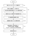
- Operation method of the slit lamp microscope system 6 is an example of a flowchart illustrating the procedure of the operating method of the slit lamp microscope system according to the embodiment, and shows the processing contents of the above-mentioned imaging device 10 and processing device 20.
- Step S1 described below can be realized by controlling the imaging device 10 by a control program.
- Steps S2 and S3 described below can be realized by the analysis and judgment program 20g causing the computer 20 to execute these processes.
- This flowchart describes an example in which the process is started when the imaging device 10 starts capturing an image.
- Step S1 is a step (imaging step) in which the imaging unit 10 scans the eye with slit light and captures an image.
- the scan mirror 10h of the imaging device 10 scans the eye with slit light.
- the imaging means 10i moves in synchronization with the scan mirror 10h.
- the imaging means 10i captures multiple images at each predetermined angle. In other words, the imaging means 10i captures the multiple images when it stops at a predetermined angle.
- the imaging unit 10 transmits the captured images to the analysis unit 21.
- Step S2 is a step (analysis step) in which the analysis unit 21 analyzes the images acquired from the imaging device 10 using AI.
- the analysis unit 21 discards images that do not include an image of the desired eye from the acquired images (step S21).
- the analysis unit 21 creates an average image of the images that were not discarded (step S22).
- the analysis unit 21 acquires one average image from multiple images captured at each predetermined angle.
- the analysis unit 21 acquires multiple average images (the number of times the camera stops at each predetermined angle) for one scan of one eye.
- the analysis unit 21 creates a dataset for AI analysis by treating the acquired multiple average images as a single image.
- the analysis unit 21 converts the average value image into a drawn image (step S23).
- the analysis unit 21 extracts features from the average value image using LWBNA_UNet.
- LWBNA_UNet finds the center of a specific part in the average value image, sets the part as the center of the created frame, detects feature points in the region of interest, and outputs a drawn image that shows the features of the region of interest.
- the analysis unit 21 acquires three-dimensional information about the eye from the drawn image (step S24).
- the analysis unit 21 performs fitting with a nonlinear curve to a specific portion of the drawn image to create a graph.
- Various parameters are calculated from the coordinates of the created graph.
- Step S3 is a step in which the determination unit 22 determines the eye condition based on the analysis results of the analysis unit 21 (determination step).
- the determination unit 22 determines the eye condition as at least one of cataract, glaucoma, keratoconus, and amyloidosis based on the analysis results of the analysis unit 21.
- the determination unit 22 determines the eye condition by comparing the three-dimensional information of the eye calculated by the analysis unit 21 with a threshold value for each eye condition, and creates a determination result.
- Step S4 is a step in which the output unit 23 outputs the judgment result created by the judgment unit 22 (output step).
- the output unit 23 displays a judgment image on the output device 3 in which the three-dimensional information of the eye calculated by the analysis unit 21 and the judgment result of the judgment unit 22 are superimposed on an average value image for each predetermined angle. After the judgment result is recorded in the memory unit 24, this flow ends.
- the imaging device (imaging section) 10 captures images.
- the imaging device 10 includes a light source 10a, a cylindrical lens 10g that forms a slit light, a scan mirror 10h that scans the eye, and an imaging means 10i.
- the scan mirror 10h and the imaging means 10i move in sync. Because the imaging device (imaging section) 10 has a simple structure, it is low cost and the examination device can be introduced in a wide range of institutions. Furthermore, the synchronous movement of the scan mirror 10h and the imaging means 10i allows the eye to be accurately imaged.
- the scan mirror 10h and the imaging means 10i stop synchronously at a predetermined angle, and the imaging means 10i takes multiple images when it stops. This makes it possible to obtain a highly accurate image of the entire surface of the eye.
- the analysis unit 21 performs the analysis.
- the analysis unit 21 discards, from among the multiple captured images, any images that do not include an image of the desired eye, and creates an image by averaging the multiple captured images that were not discarded. By discarding the first two to three frames from the captured image, it is possible to eliminate the blurry image that appears immediately after the start of imaging. In addition, by averaging the multiple images that were not discarded, an image in which the cornea and lens are clearly visible can be obtained even when the amount of light from the slit light is low.
- the analysis unit 21 converts the acquired image into a rendered image that shows the characteristic parts of the cornea, iris, and pupil. This allows AI testing to be performed without placing a heavy load on the CPU, prevents the device from becoming larger, and improves the image processing capacity required to determine various different eye conditions.
- the analysis unit 21 obtains three-dimensional information about the eye from multiple drawn images obtained at each predetermined angle. This makes it possible to obtain information that quantitatively indicates the condition of the eye.
- the determination unit 22 performs the determination.
- the determination unit 22 determines the eye condition as at least one of cataract, glaucoma, keratoconus, and amyloidosis based on the analysis results of the analysis unit 21. This makes it possible to identify the eye condition.
- the judgment unit 22 when judging the eye condition, the judgment unit 22 weights the image at a predetermined angle that is optimal for the eye condition to be judged. This makes it possible to judge the eye condition more accurately.
- the conversion to a drawn image is performed by adding an attention block to an image segmentation algorithm (UNet) and using a lightweight AI algorithm (LWBNA_UNet) that performs continuous channel narrowing in intermediate blocks.
- LWBNA_UNet a lightweight AI algorithm
- the imaging device 10 and the processing device 20 described above are merely examples and are not limited to those described above.
- the imaging device 10 is described on the premise that the imaging device 10 transmits images to the processing device 20 in real time during imaging. In this case, analysis and judgment in the processing device 20 may also be performed in real time. However, this is not limited to this, and the imaging device 10 may store the captured image in a memory, and the processing device 20 may acquire the image after imaging. In this case, analysis and judgment in the processing device 20 may be performed after the image is acquired after shooting.
- the assessment unit 22 of the processing device 20 may record the assessment results of the subject and compare the current assessment result with the previous or previous assessment results to assess the degree of progression of the eye condition.
- the assessment image may show the degree of progression of the eye condition.
Landscapes
- Life Sciences & Earth Sciences (AREA)
- Health & Medical Sciences (AREA)
- Medical Informatics (AREA)
- Biophysics (AREA)
- Ophthalmology & Optometry (AREA)
- Engineering & Computer Science (AREA)
- Biomedical Technology (AREA)
- Heart & Thoracic Surgery (AREA)
- Physics & Mathematics (AREA)
- Molecular Biology (AREA)
- Surgery (AREA)
- Animal Behavior & Ethology (AREA)
- General Health & Medical Sciences (AREA)
- Public Health (AREA)
- Veterinary Medicine (AREA)
- Eye Examination Apparatus (AREA)
Priority Applications (2)
| Application Number | Priority Date | Filing Date | Title |
|---|---|---|---|
| PCT/JP2023/028635 WO2025032657A1 (ja) | 2023-08-04 | 2023-08-04 | 細隙灯顕微鏡システム、プログラム、プログラムを記録したコンピュータ読み取り可能な記録媒体及び細隙灯顕微鏡システムの作動方法 |
| JP2025538938A JPWO2025032657A1 (https=) | 2023-08-04 | 2023-08-04 |
Applications Claiming Priority (1)
| Application Number | Priority Date | Filing Date | Title |
|---|---|---|---|
| PCT/JP2023/028635 WO2025032657A1 (ja) | 2023-08-04 | 2023-08-04 | 細隙灯顕微鏡システム、プログラム、プログラムを記録したコンピュータ読み取り可能な記録媒体及び細隙灯顕微鏡システムの作動方法 |
Publications (1)
| Publication Number | Publication Date |
|---|---|
| WO2025032657A1 true WO2025032657A1 (ja) | 2025-02-13 |
Family
ID=94534341
Family Applications (1)
| Application Number | Title | Priority Date | Filing Date |
|---|---|---|---|
| PCT/JP2023/028635 Pending WO2025032657A1 (ja) | 2023-08-04 | 2023-08-04 | 細隙灯顕微鏡システム、プログラム、プログラムを記録したコンピュータ読み取り可能な記録媒体及び細隙灯顕微鏡システムの作動方法 |
Country Status (2)
| Country | Link |
|---|---|
| JP (1) | JPWO2025032657A1 (https=) |
| WO (1) | WO2025032657A1 (https=) |
Citations (1)
| Publication number | Priority date | Publication date | Assignee | Title |
|---|---|---|---|---|
| WO2021256130A1 (ja) * | 2020-06-17 | 2021-12-23 | 株式会社トプコン | スリットランプ顕微鏡 |
-
2023
- 2023-08-04 JP JP2025538938A patent/JPWO2025032657A1/ja active Pending
- 2023-08-04 WO PCT/JP2023/028635 patent/WO2025032657A1/ja active Pending
Patent Citations (1)
| Publication number | Priority date | Publication date | Assignee | Title |
|---|---|---|---|---|
| WO2021256130A1 (ja) * | 2020-06-17 | 2021-12-23 | 株式会社トプコン | スリットランプ顕微鏡 |
Non-Patent Citations (1)
| Title |
|---|
| KOYAMA, AYUMI. MIYAZAKI, DAI. EHARA, FUMIE. SHIMIZU, YUMIKO. INOUE, YOSHITSUGU. NAKAGAWA, YUJI. AYATSUKA, YUJI.: "AI diagnosis of corneal infections against clinical and web-based anterior-segment slit lamp images", ABSTRACTS OF THE 2ND ANNUAL MEETING OF THE JSAIO, 21 November 2021 (2021-11-21), pages 10 - 19, XP009561691 * |
Also Published As
| Publication number | Publication date |
|---|---|
| JPWO2025032657A1 (https=) | 2025-02-13 |
Similar Documents
| Publication | Publication Date | Title |
|---|---|---|
| JP7478216B2 (ja) | 眼科装置、眼科装置の制御方法、及びプログラム | |
| US9615734B2 (en) | Ophthalmologic apparatus | |
| JP7194136B2 (ja) | 眼科装置、眼科装置の制御方法、及びプログラム | |
| JP7368568B2 (ja) | 眼科装置 | |
| JP2023138577A (ja) | スリットランプ顕微鏡 | |
| JP2024028448A (ja) | スリットランプ顕微鏡 | |
| JP7332463B2 (ja) | 制御装置、光干渉断層撮影装置、光干渉断層撮影装置の制御方法、及びプログラム | |
| JP2014509544A (ja) | 追跡を利用してヒト眼球の測定値を効率的に取得するためのシステムおよび方法 | |
| JP7348374B2 (ja) | 眼科情報処理装置、眼科撮影装置、眼科情報処理方法、及びプログラム | |
| JP2013153879A (ja) | 画像処理装置、画像処理装置の制御方法、眼科装置、眼科装置の制御方法、眼科システムおよびプログラム | |
| US20160066778A1 (en) | Ophthalmologic apparatus and ophthalmologic apparatus control method | |
| JP2022007433A (ja) | スリットランプ顕微鏡 | |
| JP2025147226A (ja) | 画像処理方法、画像処理装置、及び画像処理プログラム | |
| JP5038925B2 (ja) | 眼科測定装置 | |
| JP7560303B2 (ja) | スリットランプ顕微鏡システム | |
| JP4751689B2 (ja) | 眼球表面解析システム | |
| JP7560300B2 (ja) | スリットランプ顕微鏡システム | |
| JP7446730B2 (ja) | 画像処理装置、画像処理方法及びプログラム | |
| WO2025032657A1 (ja) | 細隙灯顕微鏡システム、プログラム、プログラムを記録したコンピュータ読み取り可能な記録媒体及び細隙灯顕微鏡システムの作動方法 | |
| JP2017217119A (ja) | 眼科装置、および眼科装置制御プログラム | |
| JP7786902B2 (ja) | 眼科装置、眼科装置を制御する方法、プログラム、及び記録媒体 | |
| CN111787843A (zh) | 血流测量装置 | |
| JP7811885B2 (ja) | 眼科装置、眼科装置を制御する方法、プログラム、及び記録媒体 | |
| WO2022097620A1 (ja) | 眼科情報処理装置、眼科装置、眼科情報処理方法、及びプログラム | |
| JP7643899B2 (ja) | グレード評価装置、眼科撮影装置、プログラム、記録媒体、およびグレード評価方法 |
Legal Events
| Date | Code | Title | Description |
|---|---|---|---|
| 121 | Ep: the epo has been informed by wipo that ep was designated in this application |
Ref document number: 23948377 Country of ref document: EP Kind code of ref document: A1 |
|
| ENP | Entry into the national phase |
Ref document number: 2025538938 Country of ref document: JP Kind code of ref document: A |
|
| WWE | Wipo information: entry into national phase |
Ref document number: 2025538938 Country of ref document: JP |
|
| WWE | Wipo information: entry into national phase |
Ref document number: 202617012193 Country of ref document: IN |