WO2025028627A1 - 偏波保持ファイバ - Google Patents
偏波保持ファイバ Download PDFInfo
- Publication number
- WO2025028627A1 WO2025028627A1 PCT/JP2024/027622 JP2024027622W WO2025028627A1 WO 2025028627 A1 WO2025028627 A1 WO 2025028627A1 JP 2024027622 W JP2024027622 W JP 2024027622W WO 2025028627 A1 WO2025028627 A1 WO 2025028627A1
- Authority
- WO
- WIPO (PCT)
- Prior art keywords
- less
- polarization
- maintaining fiber
- mode field
- wavelength
- Prior art date
- Legal status (The legal status is an assumption and is not a legal conclusion. Google has not performed a legal analysis and makes no representation as to the accuracy of the status listed.)
- Pending
Links
Images


Classifications
-
- G—PHYSICS
- G02—OPTICS
- G02B—OPTICAL ELEMENTS, SYSTEMS OR APPARATUS
- G02B6/00—Light guides; Structural details of arrangements comprising light guides and other optical elements, e.g. couplings
- G02B6/02—Optical fibres with cladding with or without a coating
- G02B6/024—Optical fibres with cladding with or without a coating with polarisation maintaining properties
Definitions
- the present invention relates to polarization-maintaining fiber.
- Patent Document 1 An example of a polarization-maintaining fiber is described in the following Patent Document 1.
- a polarization-maintaining fiber in which the core is sandwiched between a pair of stress-applying parts.
- Such polarization-maintaining fibers are sometimes called PANDA fibers.
- glass doped with boron oxide is used as the stress-applying part, and it is known that the stress-applying part has a lower refractive index than the cladding. Therefore, in such polarization-maintaining fibers, the light propagating through the core does not easily leak to the stress-applying part side.
- the polarization-maintaining fiber when the polarization-maintaining fiber is bent in the S-axis direction, the amount of light leaking from the F-axis direction perpendicular to the S-axis does not change much compared to when the polarization-maintaining fiber is not bent.
- the bending direction of the polarization-maintaining fiber may be bent in a direction other than the S-axis direction. In a direction other than the S-axis direction, there may be no stress-applying part, or the distance from the core to the stress-applying part may be large.
- the polarization-maintaining fiber when the polarization-maintaining fiber is bent in a direction other than the S-axis direction, the light propagating through the core is likely to leak from that bending direction. For this reason, when a polarization-maintaining fiber is twisted and bent, the light propagating through the core is likely to leak in a direction other than the S-axis direction. Therefore, when a twist is applied to a polarization-maintaining fiber, the macrobend loss characteristic, which is an optical fiber characteristic, tends to deteriorate. For this reason, there is a demand for a polarization-maintaining fiber that suppresses deterioration of the macrobend loss characteristic even when a twist is applied to the polarization-maintaining fiber.
- the present invention aims to provide a polarization-maintaining fiber that suppresses the deterioration of macrobend loss characteristics even when a twist is applied to the polarization-maintaining fiber.
- a first aspect of the present invention is a polarization-maintaining fiber comprising: a core; a pair of stress-applying parts arranged at positions sandwiching the core; and a cladding containing the core and the pair of stress-applying parts; the mode field diameter at a wavelength of 1.31 ⁇ m is 9.2 ⁇ m or less; the cutoff wavelength when the fiber length is 2 m and the bending radius is 140 mm is 1.15 ⁇ m or more and less than 1.31 ⁇ m; and the polarization-maintaining fiber satisfies at least one of the following (1) and (2): (1) When the bending radius is 7.5 mm and the twist is one turn per 47.1 mm of fiber length, the macrobend loss at a wavelength of 1.31 ⁇ m is 0.76 dB/1 turn or less. (2) When the bending radius is 10 mm and the twist is one turn per 62.8 mm of fiber length, the macrobend loss at a wavelength of 1.31 ⁇
- the mode field diameter at a wavelength of 1.31 ⁇ m is 9.2 ⁇ m or less, and thus the light confinement force can be increased compared to when the mode field diameter at that wavelength is greater than 9.2 ⁇ m.
- the cutoff wavelength is 1.15 ⁇ m or more, and thus the light confinement force can be increased compared to when the cutoff wavelength is smaller than 1.15 ⁇ m. This makes it possible to suppress the loss of light propagating through the core.
- the polarization-maintaining fiber of the present invention can suppress the deterioration of macrobend loss characteristics even when a twist is applied to the polarization-maintaining fiber, compared to a polarization-maintaining fiber that does not satisfy the above configuration.
- the present invention can provide a polarization-maintaining fiber that suppresses deterioration of macrobend loss characteristics even when a twist is applied to the polarization-maintaining fiber.
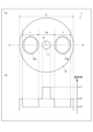
- FIG. 1 illustrates a polarization-maintaining fiber according to an embodiment of the present invention.
- FIG. 13 is a diagram showing the distribution of relative refractive index difference along the fast axis direction.
- FIG. 13 is a diagram showing the distribution of the relative refractive index difference along the slow axis direction.
- FIG. 1 is a diagram showing a polarization-maintaining fiber according to this embodiment.
- (a) is a cross-sectional view showing the transverse section of the polarization-maintaining fiber according to this embodiment
- (b) is a diagram showing the refractive index distribution along line A-A of the cross section shown in (a) of FIG. 1.
- the transverse section is a cross section perpendicular to the central axis C of the polarization-maintaining fiber 1.
- the polarization-maintaining fiber 1 includes a core 11, a pair of stress-applying portions 12a, 12b arranged on either side of the core 11, and a cladding 13 that contains the core 11 and the pair of stress-applying portions 12a, 12b.
- the polarization-maintaining fiber 1 may also include a coating that covers the cladding 13.
- a polarization-maintaining fiber 1 configured in this manner may be referred to as a PANDA (Polarization-maintaining AND Absorption-reducing) fiber. In other words, it may be referred to as a PANDA-type polarization-maintaining fiber.
- the core 11 has a columnar shape extending in the direction of the central axis C of the polarization-maintaining fiber 1, which passes roughly through the center of the cladding 13. Therefore, the central axis C of the polarization-maintaining fiber and the central axis of the core are roughly the same. Therefore, in the following description, the central axis of the core and the polarization-maintaining fiber will be described as the central axis C.
- the refractive index n11 of the core is higher than the refractive index n13 of the cladding 13.
- the core 11 is made of, for example, quartz glass doped with an up-dopant such as germanium (Ge).
- the number of cores 11 may be one, or two or more.
- the relative refractive index difference ⁇ 11 of the core 11 with respect to the cladding 13 is preferably 0.31% or more.
- the relative refractive index difference ⁇ 11 is more preferably 0.33% or more.
- the relative refractive index difference ⁇ 11 of 0.33% or more the light confinement force to the core 11 can be increased and the leakage of light from the core 11 can be suppressed compared to when the relative refractive index difference ⁇ 11 is less than 0.33%.
- the relative refractive index difference ⁇ 11 is preferably 0.37% or less. It is possible to suppress the mode field diameter of the light propagating through the core 11 from becoming too small, and to suppress the loss of light at the connection point with another optical fiber or optical device. Therefore, the relative refractive index difference ⁇ 11 is preferably 0.31% or more and 0.37% or less in order to balance the light confinement power and the light loss at the connection point, and more preferably 0.33% or more and 0.37% or less.
- optical device examples include, for example, (1) telecom optical devices such as transceivers for intercity networks and submarine networks, or optical devices for datacom such as CPO (Co-packaged Optics) modules (CPO switch modules, etc.) and pluggable transceivers (coherent optical transceivers, etc.), (2) optical devices for amplifiers, and (3) optical devices for sensors.
- CPO Co-packaged Optics
- pluggable transceivers coherent optical transceivers, etc.
- optical devices for amplifiers examples include, for example, (1) telecom optical devices such as transceivers for intercity networks and submarine networks, or optical devices for datacom such as CPO (Co-packaged Optics) modules (CPO switch modules, etc.) and pluggable transceivers (coherent optical transceivers, etc.), (2) optical devices for amplifiers, and (3) optical devices for sensors.
- the “optical device” described below is used to include the optical devices in (1) to (3) above.
- the refractive index distribution of the core 11 relative to the cladding 13 is step-shaped.
- the refractive index distribution is not limited to a step-shaped distribution, and may be, for example, a GI-type distribution.
- the refractive index distribution of the core 11 relative to the cladding 13 may have another shape.
- the cross-sectional shape of the core 11 in this embodiment is generally circular.
- the cross-sectional shape of the core 11 is not limited to circular, and may be, for example, elliptical, crescent, or noncircular.
- the cross-sectional shape of the core 11 here refers to the shape of a cross section perpendicular to the central axis C of the polarization-maintaining fiber 1.
- the radius of the core is preferably 4 ⁇ m or less.
- the radius of the core 11 is preferably 3.8 ⁇ m or more.
- the radius of the core 11 is more preferably 3.8 ⁇ m or more and 4 ⁇ m or less.
- the radius of the core 11 is, for example, half the size of the average value of the diameter of the core 11 in the direction perpendicular to the central axis C.
- the radius of the core 11 is not particularly limited as long as the cutoff wavelength described later satisfies any one of the preferable conditions for the cutoff wavelength that satisfies ⁇ Condition 2> or (3) or (4) described later.
- the pair of stress-applying parts 12a, 12b have a columnar shape extending along the central axis C, but may have a shape other than a columnar shape.
- the refractive index n12 of the stress-applying parts 12a, 12b is lower than the refractive index n13 of the cladding 13.
- the stress-applying parts 12a, 12b are made of, for example, quartz glass doped with a down dopant such as boron oxide (B 2 O 3 ).
- the cross-sectional shape of the stress-applying parts 12a, 12b may be an isosceles trapezoid with the upper base (shorter base) facing the core 11.
- one or both of the upper base and the lower base (longer base) of the stress-applying parts 12a, 12b may be an arc shape bulging in a direction away from the core 11.
- the polarization-maintaining fiber 1 in which the stress-applying parts 12a, 12b have an isosceles trapezoid shape is sometimes called a "bow-tie type polarization-maintaining fiber".
- the polarization-maintaining fiber 1 is not limited to the above-mentioned PANDA type polarization-maintaining fiber, but may be a bow-tie type polarization-maintaining fiber.
- the relative refractive index difference ⁇ 12 of the stress-applying parts 12a, 12b with respect to the cladding 13 is preferably -0.78% or less.
- the stress-applying parts 12a, 12b can function as low refractive index layers in the S-axis direction along the direction in which the stress-applying parts 12a, 12b are arranged, and leakage of light from the core 11 can be further suppressed.
- the relative refractive index difference ⁇ 12 is preferably -1.0% or more.
- the relative refractive index difference ⁇ 12 is -1.0% or more, the amount of boron oxide added can be sufficiently small, and deliquescence of the stress-applying parts 12a, 12b can be prevented. Moreover, the relative refractive index difference ⁇ 12 is more preferably -1.0% or more and -0.78% or less.
- the cross-sectional shape of the stress applying parts 12a and 12b in this embodiment is generally circular as shown by the solid line in FIG. 1, or generally elliptical with the arrangement direction of the stress applying parts 12a and 12b as the minor axis direction as shown by the dashed line.
- the cross-sectional shape of the stress applying parts 12a and 12b is not limited to circular or elliptical, and may be, for example, crescent or noncircular.
- the cross-sectional shape of the stress applying parts 12a and 12b here refers to the shape of a cross section perpendicular to the central axis C of the polarization-maintaining fiber 1.
- the diameter t of the stress applying parts 12a and 12b along the S-axis direction is preferably 24.8 ⁇ m or more, and more preferably 30.0 ⁇ m or more. This allows sufficient stress to be applied to the core 11, and as a result, the polarization-maintaining function can be preferably realized. Also, the diameter t is preferably 40.0 ⁇ m or less, more preferably 38.0 ⁇ m or less, and even more preferably 34.4 ⁇ m or less. This allows the stress applying parts 12a and 12b to be suitably arranged inside the cladding 13, which has a diameter of 125 ⁇ m ⁇ 1 ⁇ m.
- the diameter t is preferably 24.8 ⁇ m or more and 40.0 ⁇ m or less, more preferably 24.8 ⁇ m or more and 38.0 ⁇ m or less, even more preferably 24.8 ⁇ m or more and 34.4 ⁇ m or less, and preferably 30.0 ⁇ m or more and 40.0 ⁇ m or less, preferably 30.0 ⁇ m or more and 38.0 ⁇ m or less, and even more preferably 30.0 ⁇ m or more and 34.4 ⁇ m or less.
- the diameter of the cladding 13 described below is 80 ⁇ m ⁇ 1 ⁇ m
- the diameter t of the stress applying portions 12a, 12b along the S-axis direction is 22.0 ⁇ m or more. This allows sufficient stress to be applied to the core 11, and as a result, the polarization maintaining function can be suitably realized.
- the diameter t is 27.0 ⁇ m or less. This allows the stress applying portions 12a, 12b to be suitably arranged inside the cladding 13, which has a diameter of 80 ⁇ m ⁇ 1 ⁇ m.
- the diameter of the cladding 13 is 80 ⁇ m ⁇ 1 ⁇ m
- the diameter t is 22.0 ⁇ m or more and 27.0 ⁇ m or less.
- the stress applying portions 12a and 12b are each spaced apart from the core 11. This reduces the possibility that the core 11 will be subjected to unexpected deformation due to stress from the stress applying portions 12a and 12b when the polarization-maintaining fiber 1 is manufactured by melt drawing.
- the core 11 is in contact with the stress applying portions 12a and 12b, and boron oxide is added to the stress applying portions 12a and 12b, the boron oxide may cause a deterioration in transmission loss.
- this deterioration in transmission loss can be suppressed.
- the interval between the stress applying portion 12a and the stress applying portion 12b is 2a, and the distance from the central axis C of the core 11 to the stress applying portion 12a, 12b is a.
- the distance a refers to the distance from the center of the core 11 to the point included in the stress applying portion 12a that is closest to the core 11, or the distance from the center of the core 11 to the point included in the stress applying portion 12b that is closest to the core 11. It is preferable that the distance a is 10 ⁇ m or less. When the distance a is 10 ⁇ m or less, the stress applying portions 12a, 12b, which have a lower refractive index than the cladding 13, are closer to the core 11 than when the distance a is greater than 10 ⁇ m.
- the function of the stress applying portions 12a, 12b as a low refractive index layer in the S-axis direction can be improved, and the leakage of light from the core 11 can be further suppressed.
- the ratio of the distance a to the radius of the mode field diameter MFD (a/(MFD/2)) is 1.05 ⁇ m or more.
- the stress-applying parts 12a and 12b are disposed outside the mode field, and therefore, when boron oxide is added to the stress-applying parts 12a and 12b, the deterioration of the transmission loss caused by the boron oxide can be suppressed.
- the distance between the core 11 and the stress-applying parts 12a and 12b is preferably 1 ⁇ m or more. As long as the distance a satisfies any one of the conditions (1), (2), (3), or (4) of ⁇ Condition 3> described later, the size of the diameter t described above is not particularly limited.
- the cladding 13 has a columnar shape extending along the direction of the central axis C. As described above, the refractive index n13 of the cladding 13 is lower than the refractive index n11 of the core 11 and higher than the refractive index n12 of the stress applying portions 12a and 12b.
- the cladding 13 is made of, for example, quartz glass.
- the cross-sectional shape of the cladding 13 in this embodiment is generally circular.
- the cross-sectional shape of the cladding 13 is not limited to this, and may be, for example, elliptical, crescent, or noncircular.
- the cross-sectional shape of the cladding 13 here refers to the shape of a cross section perpendicular to the central axis C of the polarization-maintaining fiber 1.
- the diameter b of the cladding 13 is preferably approximately 80 ⁇ m ⁇ 1 ⁇ m, i.e., 79 ⁇ m or more and 81 ⁇ m or less, and more preferably 80 ⁇ m.
- the installation area can be kept small when storing in an optical transceiver or when applying to a sensor, so that high-density mounting can be achieved.
- the rigidity of the polarization-maintaining fiber 1 can be kept small, so that the decrease in the mechanical strength of the polarization-maintaining fiber 1 when the polarization-maintaining fiber 1 is twisted can be reduced.
- the polarization-maintaining fiber 1 when storing in an optical device, etc., especially when the polarization-maintaining fiber 1 is wound, the polarization-maintaining fiber 1 tends to be easily twisted, and there is a concern that the macrobend loss is likely to increase.
- the polarization-maintaining fiber 1 satisfies the following conditions 1 and 2, a small-diameter polarization-maintaining fiber that can be suppressed to a loss value or less required by various optical devices, etc., can be realized even if the polarization-maintaining fiber 1 is twisted when storing in an optical device, etc.
- the diameter b of the cladding 13 is preferably 125 ⁇ m ⁇ 1 ⁇ m, that is, 124 ⁇ m or more and 126 ⁇ m or less, and more preferably 125 ⁇ m.
- a polarization-maintaining fiber having approximately the same diameter as an optical fiber generally used in communication infrastructure can be realized.
- the optical characteristics and mechanical characteristics of the optical fiber will be approximately the same as when the cladding diameter is 80 ⁇ m or 125 ⁇ m, or the variation will be within the margin of error, and will not have a significant effect on the optical characteristics and mechanical characteristics of the optical fiber.
- the cladding diameter of ⁇ 1 ⁇ m is the same as the tolerance value of the cladding diameter specified in the optical fiber standard (ITU-T).
- the cladding diameter of ⁇ 1 ⁇ m in an optical fiber with a cladding diameter of 80 ⁇ m may also correspond to the above tolerance value.
- the diameter of the cladding 13 may be 79 ⁇ m or more and 126 ⁇ m or less.
- the diameter b of the cladding 13 when the cross-sectional shape of the cladding 13 is non-circular is, for example, the average value of the diameter of the cladding 13 in the direction perpendicular to the central axis C.
- the center of the circle that constitutes the outer periphery of the core 11 coincides with the center of the circle that constitutes the outer periphery of the clad 13, but this is not limited thereto, and the center of the circle that constitutes the outer periphery of the core 11 may be included in the center of the clad 13. Therefore, when the diameter of the clad 13 is 79 ⁇ m or more and 126 ⁇ m or less, the center of the circle that constitutes the outer periphery of the core 11 may be included in the center of the clad 13.
- the center of the clad 13 refers to the inner region of a circle with a radius of 0.6 ⁇ m, whose center coincides with the center of the circle that constitutes the outer periphery of the clad 13.
- the fiber length of the polarization-maintaining fiber 1 is preferably less than 50 m, may be less than 10 m, or may be 300 mm or less.
- the fiber length of the polarization-maintaining fiber 1 is preferably 47.1 mm or more, and may be, for example, 2 m or more.
- the polarization-maintaining fiber 1 When used for a sensor, it may be often used for a length of 50 m or more as a polarization-maintaining fiber that is generally available commercially. This is because the longer the polarization-maintaining fiber, the better the measurement resolution of the sensor.
- a polarization-maintaining fiber for a sensor is used for several meters, the measurement resolution may decrease, making it difficult to use it as a sensor.
- high measurement resolution is not required like a polarization-maintaining fiber for a sensor.
- the length is less than 50 m as described above.
- the fiber length when the polarization-maintaining fiber is connected in a wound state, the fiber length may be not only less than 50 m, but may also be a single digit value of more than 300 mm and less than 10 m in consideration of storage in various optical devices, and when the polarization-maintaining fiber is connected without being wound, the fiber length may be 300 mm or less, and it is preferable to determine the fiber length according to the connection state. Therefore, the fiber length does not need to be as long as 50 m or more, and by being less than 50 m, the polarization-maintaining fiber may be less likely to interfere with various optical devices.
- the fiber length of the polarization-maintaining fiber 1 is preferably 23.55 mm or more and less than 50 m, preferably 23.55 mm or more and less than 10 m, preferably 23.55 mm or more and less than 300 mm, preferably 31.4 mm or more and less than 50 m, preferably 31.4 mm or more and less than 10 m, preferably 31.4 mm or more and less than 300 mm, preferably 47.1 mm or more and less than 50 m, preferably 47.1 mm or more and less than 10 m, preferably 47.1 mm or more and less than 300 mm, preferably 2 m or more and less than 50 m, preferably 2 m or more and less than 10 m, and preferably greater than 300 mm and less than 10 m.
- the polarization-maintaining fiber 1 configured as above satisfies the following conditions 1 to 3.
- the mode field diameter at a wavelength of 1.31 ⁇ m is 9.2 ⁇ m or less.
- the mode field diameter at a wavelength of 1.31 ⁇ m is smaller than when the mode field diameter is greater than 9.2 ⁇ m, and the light confinement effect can be improved accordingly.
- the cutoff wavelength is 1.15 ⁇ m or more and less than 1.31 ⁇ m. Note that the cutoff wavelength here refers to the cutoff wavelength of light in the LP11 mode when the fiber length is 2 m and the bending radius is 140 mm.
- a cutoff wavelength of 1.15 ⁇ m or more can improve the light confinement effect compared to a cutoff wavelength of less than 1.15 ⁇ m. Furthermore, if the above mode field diameter satisfies condition 1 and the cutoff wavelength satisfies condition 2, the refractive index distribution can be determined naturally.
- the cutoff wavelength is less than 1.31 ⁇ m
- single-mode optical transmission can be achieved when the wavelength used is 1.31 ⁇ m or more.
- macrobend loss is sometimes called bending loss. (1) When the bending radius is 7.5 mm and the twist is one turn per 47.1 mm of fiber length, the macrobend loss at a wavelength of 1.31 ⁇ m is 0.76 dB/1 turn or less. (2) When the bending radius is 10 mm and the twist is one turn per 62.8 mm of fiber length, the macrobend loss at a wavelength of 1.31 ⁇ m is 0.11 dB/1 turn or less.
- the fiber length of 47.1 mm is the fiber length when wrapped once with a bending radius of 7.5 mm
- the fiber length of 62.8 mm is the fiber length when wrapped once with a bending radius of 10 mm.
- “one wrap” refers to wrapping the polarization-maintaining fiber once around a mandrel with a diameter of 7.5 mm, or wrapping the polarization-maintaining fiber once around a mandrel with a diameter of 10 mm.
- “one wrap” is synonymous with one turn.
- the polarization-maintaining fiber 1 can realize a polarization-maintaining fiber that can suppress the macrobend loss value to the loss tolerance required for the optical device, etc., even when twisting is applied under conditions where the bending radius required as one guideline for the target value of the optical device, such as a CPO switch module, is about 7.5 mm or more.
- the case where the user applies the polarization-maintaining fiber to the optical device which will be described later, can be, for example, the case where the polarization-maintaining fiber 1 is stored in various optical devices, etc.
- the above-mentioned loss tolerance can be, for example, a value that can be applied to various optical devices.
- the measurement can be performed under the condition of 0.5 turns in the above condition 3 (1), and in this case, the fiber length of the above-mentioned polarization-maintaining fiber 1 can be less than 47.1 mm (for example, 23.55 mm), and in this case, the above-mentioned macrobend loss value can be a value proportional to 0.5 times.
- the polarization-maintaining fiber 1 satisfy the above condition (2), it is possible to realize a polarization-maintaining fiber that can suppress the macrobend loss value to a loss tolerance value required for the optical device, etc., even when twisting is applied under conditions where the bending radius required as one guideline for the target value of an optical device that requires an integrated form with a bending radius larger than about 7.5 mm is about 10 mm or more.
- the measurement may be performed under the condition of 0.5 turns in the above condition 3 (2), in which case the fiber length of the above polarization-maintaining fiber 1 may be less than 62.8 mm (e.g., 31.4 mm), in which case the above macrobend loss value may be a value proportional to 0.5 times.
- the light confinement force can be made greater than when the diameter t is less than 34.4 ⁇ m, and at least one of the above conditions (1) and (2) can be more reliably satisfied.
- the cutoff wavelength when the polarization-maintaining fiber has a fiber length of 2 m and is wound around a diameter of 280 mm is referred to as the fiber cutoff wavelength.
- the fiber cutoff wavelength was measured based on IEC 60793-1-44 as the wavelength at which the higher mode attenuates by 19.3 dB when the polarization-maintaining fiber 1 cut to a fiber length of 2 m is wound around a mandrel having a diameter of 280 mm.
- the polarization-maintaining fiber was wound around the mandrel so that the slow axis of the polarization-maintaining fiber was perpendicular to the surface of the mandrel.
- the mandrel is a rod-shaped jig with a perfectly circular cross section.
- the polarization-maintaining fiber 1 is wound around the mandrel so that the slow axis of the polarization-maintaining fiber 1 is perpendicular to the surface of the mandrel.
- R indicates the radius of the mandrel.
- ⁇ Mode field diameter> The mode field diameter was measured when light with a wavelength of 1.31 ⁇ m propagated through the core. The measurement was performed by the variable aperture method based on IEC 60793-1-45. Light with a wavelength of 1.31 ⁇ m guided through the core 11 was used to measure the mode field diameter.
- ⁇ Cladding diameter> The cladding diameter was measured by the transmitted near-field method based on IEC 60793-1-20.
- the relative refractive index difference ⁇ 11 is the relative refractive index difference of the core with respect to the cladding.
- FIG. 2 is a diagram showing the distribution of the relative refractive index difference along the fast axis direction.
- the relative refractive index difference ⁇ 11 was obtained as the average of the relative refractive index difference in a region of 90% or more of the maximum value of the relative refractive index difference of the core with respect to the cladding by the following method.
- the refractive index distribution of the core in the fast axis direction of the polarization-maintaining fiber was obtained by measurement using an interference method, the relative refractive index difference distribution on the fast axis was calculated, and the maximum value of the relative refractive index difference of the core with respect to the cladding was obtained, and then the relative refractive index difference was obtained as the average of the relative refractive index difference in a region of 90% or more of the maximum value of the relative refractive index difference of the core with respect to the cladding.
- the relative refractive index difference ⁇ 12 is the relative refractive index difference of the stress-applying part with respect to the cladding.
- FIG. 3 is a diagram showing the distribution of the relative refractive index difference along the slow axis direction.
- the relative refractive index difference ⁇ 12 was obtained as the average of the relative refractive index differences in the region (from the region corresponding to 0.5 ⁇ 12 min to the region corresponding to ⁇ 12 min in FIG. 3) that satisfies 50% or less of the minimum value of the refractive index distribution in the slow axis direction of the stress-applying part, similar to the relative refractive index difference ⁇ 11 of the core.
- the refractive index distribution of the stress-applying part in the slow axis direction of the polarization-maintaining fiber was obtained by measurement using an interference method, the relative refractive index difference distribution on the slow axis was calculated, and the minimum value of the relative refractive index difference of the stress-applying part with respect to the cladding was obtained, and then the average of the relative refractive index difference in the region that satisfies 50% or less of the minimum value of the refractive index distribution in the slow axis direction of the stress-applying part was obtained.
- the distance from the central axis of the core to the stress applying portion was obtained by measuring the fiber end face with an optical microscope.
- Stress applying part diameter was obtained by measuring the fiber end face with an optical microscope.
- macrobend loss the bending loss of light with a wavelength of 1.31 ⁇ m per turn when the polarization-maintaining fiber is wound around a mandrel with a radius of 7.5 mm or 10 mm.
- the polarization-maintaining fiber 1 when the polarization-maintaining fiber 1 is wound once so that the slow axis is perpendicular to the surface of a mandrel with a radius of 7.5 mm or 10 mm (when the bending radius is 7.5 mm or 10 mm), the power of the light in the LP01 mode from the light source at that time and the power of the light in the LP01 mode from the light source in a state before winding as a reference are measured, and the bending loss per turn is calculated from the difference between the above two powers.
- the mandrel is a rod-shaped jig with a cross-sectional shape that is a perfect circle. In the table below, R indicates the radius of the mandrel.
- the bending loss was measured when the polarization-maintaining fiber was not twisted and was wound around a mandrel with a bending radius of 10 mm for one turn, and when a similar twist was applied per turn for 62.8 mm of fiber length.
- the refractive index distribution of the core with respect to the cladding in the polarization-maintaining fibers of Examples 1 to 8 and Comparative Examples 1 to 3 is step-like.
- the bending loss was measured when the polarization-maintaining fiber was not twisted and was wound around a mandrel with a bending radius of 7.5 mm for one turn, and when a similar twist was applied per turn for 47.1 mm of fiber length.
- the bending loss of light per turn at a wavelength of 1.31 ⁇ m was measured when the bending radius was 7.5 mm and the twist was one turn per 47.1 mm of fiber length
- the bending loss of light per turn at a wavelength of 1.31 ⁇ m was measured when the bending radius was 10 mm and the twist was one turn per 62.8 mm of fiber length.
- the bending loss without twisting was measured when the slow axis was perpendicular to the surface of the mandrel. The results are shown in Tables 1 and 2.
- Examples 1 to 8 satisfy all of Conditions 1 to 3. Specifically, by satisfying Condition 1, the polarization-maintaining fibers can have a smaller mode field diameter at a wavelength of 1.31 ⁇ m than when the mode field diameter is greater than 9.2 ⁇ m, and the light confinement effect can be improved accordingly. Furthermore, by satisfying Condition 2, the polarization-maintaining fibers can have an improved light confinement effect than when the cutoff wavelength is less than 1.15 ⁇ m. This improved light confinement effect suppresses bending loss. Furthermore, by satisfying Condition 3, the polarization-maintaining fibers can have a macrobend loss value that satisfies the allowable range in optical devices such as CPO switch modules.
- the allowable range is, for example, a range in which the deterioration of the macrobend loss characteristics can be suppressed to a degree that allows a user to apply the polarization-maintaining fiber to the optical device even when a twist is applied to the polarization-maintaining fiber when it is stored in various optical devices, etc.
- the polarization-maintaining fibers of Comparative Example 1 and Comparative Example 3 have a large mode field diameter and do not satisfy Condition 1. Furthermore, these polarization-maintaining fibers do not satisfy Condition 3. Compared with the polarization-maintaining fibers of Examples 5 and 8, which have the largest macrobend loss among Examples 1 to 8, Comparative Example 1 has about 7.0 times the macrobend loss of Condition 3 (1) and about 2.3 times the macrobend loss of Condition 3 (2). Furthermore, Comparative Example 3 has about 4.4 times the macrobend loss of Condition 3 (1) and about 1.9 times the macrobend loss of Condition 3 (2). For this reason, it may be difficult to use the polarization-maintaining fibers of Comparative Example 1 and Comparative Example 3 in optical devices that satisfy the above-mentioned tolerance range, such as CPO switch modules.
- the polarization-maintaining fiber of Comparative Example 2 has a small cutoff wavelength and does not satisfy Condition 2. Furthermore, this polarization-maintaining fiber does not satisfy Condition 3, and compared to the polarization-maintaining fibers of Examples 5 and 8, which have the largest macrobend loss, the macrobend loss of Condition 3 (1) is approximately 1.9 times, and the macrobend loss of Condition 3 (2) is approximately 1.6 times. For this reason, it may be difficult to use the polarization-maintaining fiber of Comparative Example 2 in optical devices that satisfy the above-mentioned tolerance range, such as CPO switch modules.
- the relative refractive index difference ⁇ 11 of the core 11 with respect to the cladding is preferably 0.31% or more, more preferably 0.33% or more, as described above. Also, the relative refractive index difference ⁇ 11 is preferably 0.37% or less, as described above.
- the mode field diameter at a wavelength of 1.31 ⁇ m in the polarization-maintaining fiber 1 is 8.0 ⁇ m or more.
- the mode field diameter is larger than when the mode field diameter is less than 8.0 ⁇ m, light propagating from other optical fibers or optical devices may be more easily incident on the polarization-maintaining fiber at the connection point with other optical fibers or optical devices. This can reduce the connection loss. Therefore, in this case, it is possible to maintain a balance between the effect of satisfying the macrobend loss characteristics under a specified twist condition in at least one of (1) and (2) of the above condition 3 and the effect of suppressing the connection loss with other optical fibers or optical devices.
- the mode field diameter is 8.0 ⁇ m or more in order to reduce the connection loss to a level that allows operation when applied to the optical device.
- the mode field diameter at a wavelength of 1.31 ⁇ m in the polarization-maintaining fiber 1 is 8.2 ⁇ m or less, and more preferably greater than 8.0 ⁇ m.
- the cutoff wavelength is 1.15 ⁇ m or more and less than 1.31 ⁇ m. In this case, as is clear from each example, macrobend loss can be further suppressed.
- the macrobend loss is smaller than the macrobend loss value of 0.5 dB at a wavelength of 1.55 ⁇ m when wound 10 times around a mandrel with a bending radius of 7.5 mm as specified in ITU-T standard G657.A2, and is smaller than the macrobend loss value of 0.1 dB at a wavelength of 1.55 ⁇ m when wound 10 times around a mandrel with a bending radius of 10 mm.
- the macrobend loss is smaller than the macrobend loss value of 0.5 dB at a wavelength of 1.55 ⁇ m when wound 10 times around a mandrel with a bending radius of 10 mm as specified in ITU-T standard G657.A2, which requires stricter macrobend loss conditions.
- the macrobend loss at a wavelength of 1.55 ⁇ m can be 0.08 dB or less.
- the mode field diameter is less than 8.6 ⁇ m.
- an optical element for converting the mode field diameter (lens, spot size converter, etc.) is arranged between the optical fiber and the modulator, the mode field diameter is prevented from becoming complicated and large. Since the mode field diameter is smaller than the standard value of the mode field diameter specified in the standard G657.A and standard G657.B, which require strict macrobend loss conditions, the optical element used below the standard value can be made smaller. In particular, when an optical fiber with a cladding diameter of 80 ⁇ 1 ⁇ m is used, the entire optical device including the optical fiber, the optical element for converting the mode field diameter, and the modulator can be made smaller.
- the mode field diameter is 8.0 ⁇ m or more and less than 8.6 ⁇ m in terms of the balance between the connection loss with the optical element for converting the mode field diameter and the miniaturization of the optical element for converting the mode field diameter.
- the polarization-maintaining fiber 1 satisfies the following (A) or (B).
- A) The mode field diameter is greater than 8.5 ⁇ m and less than 9.1 ⁇ m, and the cutoff wavelength is greater than or equal to 1.22 ⁇ m and less than 1.31 ⁇ m.
- the condition 3 (3) described below can be more reliably satisfied.
- the cutoff wavelength range that satisfies the condition 3 (3) is 1.22 ⁇ m or more and less than 1.31 ⁇ m.
- the mode field diameter is less than 9.1 ⁇ m, the light confinement effect can be improved more than when the mode field diameter is 9.1 ⁇ m.
- the condition 3 (3) can be necessarily satisfied in the cutoff wavelength range even when the mode field diameter is less than 9.1 ⁇ m. Also, when the above-mentioned mode field diameter is less than 9.1 ⁇ m, if the cutoff wavelength range is 1.15 ⁇ m or more, the condition 3 (3) can be satisfied even when the cutoff wavelength is less than 1.22 ⁇ m. Furthermore, when the above-mentioned mode field diameter is less than 8.5 ⁇ m, if the cutoff wavelength range is 1.15 ⁇ m or more, condition 3 (3) can be satisfied even if the cutoff wavelength is less than 1.16 ⁇ m.
- the polarization-maintaining fiber 1 satisfies at least one of the following (C) and (D).
- C The mode field diameter is greater than 8.3 ⁇ m and less than 9.1 ⁇ m, and the cutoff wavelength is greater than or equal to 1.22 ⁇ m and less than 1.31 ⁇ m.
- D The mode field diameter is greater than 8.2 ⁇ m and not greater than 8.3 ⁇ m, and the cutoff wavelength is greater than or equal to 1.16 ⁇ m and less than 1.31 ⁇ m.
- the polarization-maintaining fiber 1 can more reliably satisfy (4) of condition 3 described below.
- the cutoff wavelength range that satisfies (4) of condition 3 is 1.16 ⁇ m or more and less than 1.31 ⁇ m.
- the mode field diameter is less than 8.3 ⁇ m, the light confinement effect can be improved compared to when the mode field diameter is 8.3 ⁇ m. Therefore, if the cutoff wavelength range that satisfies (4) of condition 3 when the mode field diameter is 8.3 ⁇ m is satisfied, condition 3 (4) can be necessarily satisfied in that cutoff wavelength range even when the mode field diameter is less than 8.3 ⁇ m.
- condition 3 when the above-mentioned mode field diameter is less than 9.1 ⁇ m, if the cutoff wavelength range is 1.15 ⁇ m or more, at least one of (4) of condition 3 can be satisfied even when the cutoff wavelength is less than 1.22 ⁇ m. Furthermore, when the above-mentioned mode field diameter is less than 8.3 ⁇ m, if the cutoff wavelength range is 1.15 ⁇ m or more, condition 3 (4) can be satisfied even if the cutoff wavelength is less than 1.16 ⁇ m.
- the cutoff wavelength of the polarization-maintaining fiber 1 is 1.15 ⁇ m or more and 1.25 ⁇ m or less when the fiber length is 2 m and the bending radius is 140 mm.
- the cutoff wavelength may shift to the long wavelength side when the fiber length is short, for example, 1 m or less. Therefore, in order to reduce the possibility that the cutoff wavelength exceeds the wavelength used due to the shift of the cutoff wavelength to the long wavelength side caused by the fiber length, making single-mode transmission at the wavelength used difficult, it is preferable that there is a certain margin between the upper limit of the cutoff wavelength when measured with a fiber length of 2 m and the wavelength used.
- the cutoff wavelength is, for example, 1.15 ⁇ m or more and 1.25 ⁇ m or less as described above, even if the cutoff wavelength shifts to the long wavelength side when the fiber length is short as described above, the cutoff wavelength can be prevented from exceeding the wavelength used. Therefore, it is possible to reduce the possibility that single-mode transmission at the wavelength used becomes difficult.
- the cutoff wavelength may be greater than 1.25 ⁇ m and less than 1.31 ⁇ m.
- the cutoff wavelength can be brought closer to the wavelength band in use, and the light confinement effect can be improved compared to when the cutoff wavelength is 1.25 ⁇ m or less. Therefore, even when the polarization-maintaining fiber 1 is twisted, the macrobend loss value can be reduced compared to when the cutoff wavelength is 1.25 ⁇ m or less.
- the cutoff wavelength is 1.22 ⁇ m or more and less than 1.31 ⁇ m.
- the fact that this cutoff wavelength can be obtained is supported by experimental data. In this case, an appropriate balance can be maintained between the high light confinement effect compared to when the cutoff wavelength is less than 1.22 ⁇ m, and the effect of reducing the possibility that single-mode transmission will become difficult at the wavelength used compared to when the cutoff wavelength is greater than 1.25 ⁇ m and less than 1.31 ⁇ m.
- the diameter of the cladding 13 is 124 ⁇ m or more and 126 ⁇ m or less
- the mode field diameter at a wavelength of 1.31 ⁇ m is 8.9 ⁇ m or more and 9.1 ⁇ m or less
- the cutoff wavelength is 1.22 ⁇ m or more and 1.25 ⁇ m or less
- the relative refractive index difference ⁇ 11 of the core 11 with respect to the cladding 13 is 0.33% or more and 0.34% or less.
- the diameter of the cladding 13 is 79 ⁇ m or more and 81 ⁇ m or less
- the mode field diameter at a wavelength of 1.31 ⁇ m is 8.0 ⁇ m or more and 9.2 ⁇ m or less
- the cutoff wavelength is 1.15 ⁇ m or more and less than 1.21 ⁇ m
- the relative refractive index difference ⁇ 11 of the core 11 with respect to the cladding 13 is 0.31% or more and 0.37% or less.
- the mode field diameter at a wavelength of 1.31 ⁇ m is 9.2 ⁇ m or less, and the cutoff wavelength is 1.15 ⁇ m or more and less than 1.21 ⁇ m.
- the mode field diameter at a wavelength of 1.31 ⁇ m is greater than 8.8 ⁇ m and less than 9.2 ⁇ m, and the cutoff wavelength is greater than or equal to 1.15 ⁇ m and less than 1.31 ⁇ m.
- the polarization-maintaining fiber 1 satisfies any one of the following (E) to (G).
- E The mode field diameter at a wavelength of 1.31 ⁇ m is 8.2 ⁇ m or less, and the cutoff wavelength is 1.15 ⁇ m or more and less than 1.31 ⁇ m.
- F The mode field diameter at a wavelength of 1.31 ⁇ m is greater than 8.2 ⁇ m and equal to or less than 8.5 ⁇ m, and the cutoff wavelength is equal to or greater than 1.16 ⁇ m and less than 1.31 ⁇ m.
- the mode field diameter at a wavelength of 1.31 ⁇ m is greater than 8.5 ⁇ m and equal to or less than 9.2 ⁇ m, and the cutoff wavelength is equal to or greater than 1.19 ⁇ m and less than 1.31 ⁇ m.
- At least one of (1) and (2) of condition 3 can be more reliably satisfied.
- the cutoff wavelength range that satisfies at least one of (1) and (2) of condition 3 is 1.19 ⁇ m or more and less than 1.31 ⁇ m.
- the mode field diameter is less than 9.2 ⁇ m, the light confinement effect can be improved more than when the mode field diameter is 9.2 ⁇ m.
- the cutoff wavelength range that satisfies at least one of (1) and (2) of condition 3 when the mode field diameter is 9.2 ⁇ m is satisfied, at least one of (1) and (2) of condition 3 can be necessarily satisfied in the cutoff wavelength range even when the mode field diameter is less than 9.2 ⁇ m.
- the cutoff wavelength range is 1.15 ⁇ m or more, at least one of (1) and (2) of condition 3 can be satisfied even if the cutoff wavelength is less than 1.19 ⁇ m.
- the cutoff wavelength range is 1.15 ⁇ m or more, at least one of (1) and (2) of condition 3 can be satisfied even if the cutoff wavelength is less than 1.16 ⁇ m.
- the polarization-maintaining fiber 1 satisfies the following (3) as ⁇ Condition 3> instead of (1) or (2) of ⁇ Condition 3>.
- the mode field diameter is 9.1 ⁇ m or less. It is also preferable that the mode field diameter is greater than 8.5 ⁇ m. Therefore, it is more preferable that the mode field diameter is greater than 8.5 ⁇ m and less than 9.1 ⁇ m. In this case, it is preferable that the cutoff wavelength is 1.22 ⁇ m or more and less than 1.31 ⁇ m. Alternatively, if (3) is satisfied, it is preferable that the mode field diameter is 8.5 ⁇ m or less. It is also preferable that the mode field diameter is greater than 8.2 ⁇ m. Therefore, it is more preferable that the mode field diameter is greater than 8.2 ⁇ m and less than 8.5 ⁇ m. In this case, it is preferable that the cutoff wavelength is 1.16 ⁇ m or more and less than 1.31 ⁇ m.
- ITU-T standard G657.A2 for low bending loss single mode optical fiber that is required to support access networks and general transport networks, and has strict macrobend loss conditions.
- This standard specifies that the bending radius is 7.5 mm at a wavelength of 1.55 ⁇ m, and the macrobend loss value when wrapped around a mandrel once is 0.5 dB.
- the polarization-maintaining fiber 1 satisfies the following (4) as ⁇ Condition 3> instead of (1) or (2) of ⁇ Condition 3>.
- the macrobend loss at a wavelength of 1.31 ⁇ m is 0.07 dB/1 turn or less.
- the mode field diameter is 9.1 ⁇ m or less. It is also preferable that the mode field diameter is greater than 8.3 ⁇ m. Therefore, it is more preferable that the mode field diameter is greater than 8.3 ⁇ m and less than 9.1 ⁇ m. If (4) is satisfied, it is preferable that the cutoff wavelength is 1.22 ⁇ m or more and less than 1.31 ⁇ m. Alternatively, if (4) is satisfied, it is preferable that the mode field diameter is 8.3 ⁇ m or less. It is also preferable that the mode field diameter is greater than 8.2 ⁇ m. Therefore, it is more preferable that the mode field diameter is greater than 8.2 ⁇ m and less than 8.3 ⁇ m. In this case, it is preferable that the cutoff wavelength is 1.16 ⁇ m or more and less than 1.31 ⁇ m.
- the ITU-T standard G657.A2 stipulates that the macrobend loss is 0.1 dB when the wavelength is 1.55 ⁇ m, the bending radius is 10 mm, and the fiber is wound around a mandrel once.
- a value equal to or less than the value of the standard can be obtained even when the wavelength is 1.31 ⁇ m, even though the polarization-maintaining fiber is twisted.
- the ITU-T standard G657.B3 which stipulates stricter macrobend loss conditions than the ITU-T standard G657.A2, stipulates that the macrobend loss is 0.08 dB when the wavelength is 1.55 ⁇ m, the bending radius is 10 mm, and the fiber is wound around a mandrel once.
- the polarization-maintaining fiber 1 can have a macrobend loss that is small enough to support access networks, general transport networks, etc.
- a first aspect of the present invention is a polarization-maintaining fiber comprising a core 11, a pair of stress-applying portions 12 a, 12 b arranged at positions sandwiching the core 11, and a cladding 13 containing the core 11 and the pair of stress-applying portions 12 a, 12 b, the mode field diameter at a wavelength of 1.31 ⁇ m being 9.2 ⁇ m or less, the cutoff wavelength being 1.15 ⁇ m or more and less than 1.31 ⁇ m, and satisfying at least one of the following (1) and (2): (1) When the bending radius is 7.5 mm and the twist is one turn per 47.1 mm of fiber length, the macrobend loss at a wavelength of 1.31 ⁇ m is 0.76 dB/1 turn or less. (2) When the bending radius is 10 mm and the twist is one turn per 62.8 mm of fiber length, the macrobend loss at a wavelength of 1.31 ⁇ m is 0.11 dB/1 turn or less.
- the light confinement force can be increased compared to when the mode field diameter at that wavelength is greater than 9.2 ⁇ m. Also, by having a cutoff wavelength of 1.15 ⁇ m or more, the light confinement force can be increased compared to when the cutoff wavelength at that wavelength is smaller than 1.15 ⁇ m. Therefore, the loss of light propagating through the core can be suppressed. Also, by having a cutoff wavelength of less than 1.31 ⁇ m, single-mode optical transmission can be achieved when the wavelength used is 1.31 ⁇ m or more.
- the polarization-maintaining fiber 1 of this embodiment can suppress the deterioration of macrobend loss characteristics to an extent that, for example, a user can apply the polarization-maintaining fiber to the optical device, even if a twist is applied to the polarization-maintaining fiber when it is stored in the optical device.
- the cutoff wavelength is a wavelength value measured at a fiber cutoff wavelength with a fiber length of 2 m, but if the method of calculating the loss per unit length of each wavelength in the LP11 mode from the refractive index structure is used, it is possible to calculate the cutoff wavelength at any length even if the fiber length is less than 2 m. Therefore, the polarization-maintaining fiber 1 of this embodiment can be used even if the fiber length is less than 2 m because it is possible to measure the cutoff wavelength.
- Aspect 2 of this embodiment is a polarization-maintaining fiber of aspect 1, characterized in that the relative refractive index difference of the core with respect to the cladding is 0.31% or more.
- Aspect 3 of the present invention is a polarization-maintaining fiber according to aspect 1 or 2, characterized in that the relative refractive index difference of the core with respect to the cladding is 0.33% or more.
- Aspect 4 of the present invention is a polarization-maintaining fiber according to any one of aspects 1 to 3, characterized in that the relative refractive index difference of the core with respect to the cladding is 0.37% or less.
- Aspect 5 of the present invention is a polarization-maintaining fiber according to any one of aspects 1 to 4, characterized in that the distance from the central axis of the core to the stress-applying portion is 10 ⁇ m or less.
- Aspect 6 of the present invention is a polarization-maintaining fiber according to any one of aspects 1 to 5, characterized in that the relative refractive index difference of the stress-applying portion with respect to the cladding is -0.78% or less.
- Aspect 7 of the present invention is a polarization-maintaining fiber according to any one of aspects 1 to 6, characterized in that the mode field diameter is 8.0 ⁇ m or more.
- Aspect 8 of the present invention is a polarization-maintaining fiber according to any one of aspects 1 to 7, characterized in that the mode field diameter is 8.2 ⁇ m or less.
- a ninth aspect of the present invention is the polarization-maintaining fiber according to any one of the first to eighth aspects, which satisfies the following (A) or (B):
- (A) The mode field diameter is greater than 8.5 ⁇ m and less than 9.1 ⁇ m, and the cutoff wavelength is greater than or equal to 1.22 ⁇ m and less than 1.31 ⁇ m.
- (B) The mode field diameter is greater than 8.2 ⁇ m and not greater than 8.5 ⁇ m, and the cutoff wavelength is greater than or equal to 1.16 ⁇ m and less than 1.31 ⁇ m.
- a tenth aspect of the present invention is the polarization-maintaining fiber according to any one of the first to ninth aspects, which satisfies the following (A) or (B):
- (A) The mode field diameter is greater than 8.3 ⁇ m and less than 9.1 ⁇ m, and the cutoff wavelength is greater than or equal to 1.22 ⁇ m and less than 1.31 ⁇ m.
- (B) The mode field diameter is greater than 8.2 ⁇ m and not greater than 8.3 ⁇ m, and the cutoff wavelength is greater than or equal to 1.16 ⁇ m and less than 1.31 ⁇ m.
- Aspect 11 of the present invention is a polarization-maintaining fiber according to any one of aspects 1 to 10, characterized in that the cutoff wavelength is 1.15 ⁇ m or more and 1.25 ⁇ m or less.
- Aspect 12 of the present invention is a polarization-maintaining fiber according to any one of aspects 1 to 11, characterized in that the cutoff wavelength is greater than 1.25 ⁇ m and less than 1.31 ⁇ m.
- Aspect 13 of the present invention is a polarization-maintaining fiber according to any one of aspects 1 to 12, characterized in that the cutoff wavelength is 1.22 ⁇ m or more and less than 1.31 ⁇ m.
- Aspect 14 of the present invention is a polarization-maintaining fiber according to any one of aspects 1 to 13, characterized in that the diameter of the cladding is 124 ⁇ m or more and 126 ⁇ m or less, the mode field diameter is 8.9 ⁇ m or more and 9.1 ⁇ m or less, the cutoff wavelength is 1.22 ⁇ m or more and 1.25 ⁇ m or less, and the relative refractive index difference of the core with respect to the cladding is 0.33% or more and 0.34% or less.
- Aspect 15 of the present invention is a polarization-maintaining fiber according to any one of aspects 1 to 14, characterized in that the diameter of the cladding is 79 ⁇ m or more and 81 ⁇ m or less, the mode field diameter is 8.0 ⁇ m or more and 9.2 ⁇ m or less, the cutoff wavelength is 1.15 ⁇ m or more and less than 1.21 ⁇ m, and the relative refractive index difference of the core with respect to the cladding is 0.31% or more and 0.37% or less.
- Aspect 16 of the present invention is a polarization-maintaining fiber according to any one of aspects 1 to 15, characterized in that the mode field diameter is 9.2 ⁇ m or less, and the cutoff wavelength is greater than 1.15 ⁇ m and less than 1.20 ⁇ m.
- Aspect 17 of the present invention is a polarization-maintaining fiber according to any one of aspects 1 to 16, characterized in that the mode field diameter is greater than 8.8 ⁇ m and less than 9.2 ⁇ m, and the cutoff wavelength is greater than or equal to 1.15 ⁇ m and less than 1.31 ⁇ m.
- An eighteenth aspect of the present invention is a polarization-maintaining fiber according to any one of claims 1 to 17, characterized in that it satisfies any one of the following (E) to (G).
- E The mode field diameter is 8.2 ⁇ m or less, and the cutoff wavelength is 1.15 ⁇ m or more and less than 1.31 ⁇ m.
- F The mode field diameter is greater than 8.2 ⁇ m and not greater than 8.5 ⁇ m, and the cutoff wavelength is greater than or equal to 1.16 ⁇ m and less than 1.31 ⁇ m.
- G The mode field diameter is greater than 8.5 ⁇ m and not greater than 9.2 ⁇ m, and the cutoff wavelength is greater than or equal to 1.19 ⁇ m and less than 1.31 ⁇ m.
- a nineteenth aspect of the present invention is the polarization-maintaining fiber according to any one of the first to eighteenth aspects, which satisfies the following (3): (3) The macrobend loss at a wavelength of 1.31 ⁇ m when the bending radius is 7.5 mm and the twist is one turn per 47.1 mm of fiber length is 0.49 dB/1 turn or less.
- a twentieth aspect of the present invention is the polarization-maintaining fiber according to any one of the first to nineteenth aspects, which satisfies the following (4): (4) When the bending radius is 10 mm and the twist is one turn per 62.8 mm of fiber length, the macrobend loss at a wavelength of 1.31 ⁇ m is 0.07 dB/1 turn or less.
- Aspect 21 of the present invention is a polarization-maintaining fiber according to any one of aspects 1 to 20, characterized in that the mode field diameter is less than 8.6 ⁇ m.
- Aspect 22 of the present invention is a polarization-maintaining fiber according to any one of aspects 1 to 21, characterized in that the fiber length is 47.1 mm or more.
- Aspect 23 of the present invention is a polarization-maintaining fiber according to any one of aspects 1 to 22, characterized in that the fiber length is less than 50 m.
- Aspect 24 of the present invention is a polarization-maintaining fiber according to any one of aspects 1 to 23, characterized in that the fiber length is less than 10 m.
- Aspect 25 of the present invention is a polarization-maintaining fiber according to any one of aspects 1 to 24, characterized in that the fiber length is less than 300 mm.
- Aspect 26 of the present invention is a polarization-maintaining fiber according to any one of aspects 1 to 25, characterized in that the refractive index profile of the core relative to the cladding is step-like or GI-type profile.
- Aspect 27 of the present invention is a polarization-maintaining fiber according to any one of aspects 1 to 26, characterized in that the diameter of the stress-applying portion is 24.8 ⁇ m or more.
- Aspect 28 of the present invention is a polarization-maintaining fiber according to any one of aspects 1 to 27, characterized in that the diameter of the stress-applying portion is 38.0 ⁇ m or less.
- Aspect 29 of the present invention is a polarization-maintaining fiber according to any one of aspects 1 to 28, characterized in that the diameter of the stress-applying portion is 34.4 ⁇ m or less.
- Aspect 30 of the present invention is a polarization-maintaining fiber according to any one of aspects 1 to 29, characterized in that the radius of the core is 4.0 ⁇ m or less.
- Aspect 31 of the present invention is a polarization-maintaining fiber according to any one of aspects 1 to 30, characterized in that the radius of the core is 3.8 ⁇ m or more.
- Aspect 32 of the present invention is a polarization-maintaining fiber according to any one of aspects 1 to 31, characterized in that the relative refractive index difference of the stress-applying portion with respect to the cladding is -1.0% or more.
- Aspect 33 of the present invention is a polarization-maintaining fiber according to any one of aspects 1 to 32, characterized in that the ratio of the distance from the central axis of the core to the stress-applying portion to the radius of the mode field diameter is 1.05 ⁇ m or more.
- Aspect 34 of the present invention is a polarization-maintaining fiber according to any one of aspects 1 to 33, characterized in that the diameter of the cladding is 79 ⁇ m or more and 126 ⁇ m or less.
- Aspect 35 of the present invention is a polarization-maintaining fiber according to any one of aspects 1 to 34, characterized in that the diameter of the cladding is 124 ⁇ m or more and 126 ⁇ m or less.
- Aspect 36 of the present invention is a polarization-maintaining fiber according to any one of aspects 1 to 35, characterized in that the diameter of the cladding is 79 ⁇ m or more and 81 ⁇ m or less.
- Aspect 37 of the present invention is a polarization-maintaining fiber according to any one of aspects 1 to 36, characterized in that the center of the circle that constitutes the outer periphery of the core is included in the center of the cladding, the center of the cladding is a circle with a radius of 0.6 ⁇ m, and the center of the circle is an inner region of the circle that coincides with the center of the circle that constitutes the outer periphery of the cladding.
- a polarization-maintaining fiber can be provided in which the deterioration of macrobend loss characteristics is suppressed even when a twist is applied to the polarization-maintaining fiber, and it is expected to be used as a polarization-maintaining fiber for communications in fields such as optical communications, a polarization-maintaining fiber for amplifiers in fields such as amplifiers, and a polarization-maintaining fiber for sensors in fields such as measurement.
Landscapes
- Physics & Mathematics (AREA)
- General Physics & Mathematics (AREA)
- Optics & Photonics (AREA)
- Optical Fibers, Optical Fiber Cores, And Optical Fiber Bundles (AREA)
Priority Applications (2)
| Application Number | Priority Date | Filing Date | Title |
|---|---|---|---|
| CN202480050104.5A CN121605332A (zh) | 2023-08-02 | 2024-08-01 | 保偏光纤 |
| JP2025537519A JPWO2025028627A1 (https=) | 2023-08-02 | 2024-08-01 |
Applications Claiming Priority (2)
| Application Number | Priority Date | Filing Date | Title |
|---|---|---|---|
| JP2023126627 | 2023-08-02 | ||
| JP2023-126627 | 2023-08-02 |
Publications (1)
| Publication Number | Publication Date |
|---|---|
| WO2025028627A1 true WO2025028627A1 (ja) | 2025-02-06 |
Family
ID=94395429
Family Applications (1)
| Application Number | Title | Priority Date | Filing Date |
|---|---|---|---|
| PCT/JP2024/027622 Pending WO2025028627A1 (ja) | 2023-08-02 | 2024-08-01 | 偏波保持ファイバ |
Country Status (3)
| Country | Link |
|---|---|
| JP (1) | JPWO2025028627A1 (https=) |
| CN (1) | CN121605332A (https=) |
| WO (1) | WO2025028627A1 (https=) |
Citations (4)
| Publication number | Priority date | Publication date | Assignee | Title |
|---|---|---|---|---|
| JP2003337238A (ja) * | 2002-03-15 | 2003-11-28 | Fujikura Ltd | 偏波保持光ファイバ |
| JP2015184371A (ja) * | 2014-03-20 | 2015-10-22 | 株式会社フジクラ | 偏波保持光ファイバ |
| JP2018512618A (ja) * | 2015-03-20 | 2018-05-17 | コーニング インコーポレイテッド | 偏波保持光ファイバ |
| EP3715924A1 (en) * | 2018-05-22 | 2020-09-30 | Fiberhome Telecommunication Technologies Co., Ltd | Polarization maintaining optical fiber |
-
2024
- 2024-08-01 WO PCT/JP2024/027622 patent/WO2025028627A1/ja active Pending
- 2024-08-01 JP JP2025537519A patent/JPWO2025028627A1/ja active Pending
- 2024-08-01 CN CN202480050104.5A patent/CN121605332A/zh active Pending
Patent Citations (4)
| Publication number | Priority date | Publication date | Assignee | Title |
|---|---|---|---|---|
| JP2003337238A (ja) * | 2002-03-15 | 2003-11-28 | Fujikura Ltd | 偏波保持光ファイバ |
| JP2015184371A (ja) * | 2014-03-20 | 2015-10-22 | 株式会社フジクラ | 偏波保持光ファイバ |
| JP2018512618A (ja) * | 2015-03-20 | 2018-05-17 | コーニング インコーポレイテッド | 偏波保持光ファイバ |
| EP3715924A1 (en) * | 2018-05-22 | 2020-09-30 | Fiberhome Telecommunication Technologies Co., Ltd | Polarization maintaining optical fiber |
Also Published As
| Publication number | Publication date |
|---|---|
| CN121605332A (zh) | 2026-03-03 |
| JPWO2025028627A1 (https=) | 2025-02-06 |
Similar Documents
| Publication | Publication Date | Title |
|---|---|---|
| CN113099726B (zh) | 光纤 | |
| JP6486533B2 (ja) | 光ファイバ | |
| US7289687B2 (en) | Polarization-maintaining optical fiber | |
| US7046884B2 (en) | Optical fiber, optical fiber tape, optical cable and optical connector with optical fiber | |
| US20080292251A1 (en) | Polarization-maintaining optical fiber, method of manufacturing polarization-maintaining optical-fiber connecting portion, and polarization-maintaining optical-fiber connecting portion | |
| JP2010061170A (ja) | 光ファイバモジュール | |
| JP6082875B2 (ja) | 大有効面積を有する低減衰光ファイバ | |
| JP2015184371A (ja) | 偏波保持光ファイバ | |
| WO2025159182A1 (ja) | 偏波保持ファイバ | |
| JP7403574B2 (ja) | 光ファイバ | |
| JP2000347057A (ja) | 高次モード除去機能を有する多モード光ファイバ | |
| WO2012070295A1 (ja) | 光ファイバモジュール | |
| TW202217384A (zh) | 光纖電纜 | |
| WO2025028627A1 (ja) | 偏波保持ファイバ | |
| WO2025028626A1 (ja) | 偏波保持ファイバ | |
| WO2025028628A1 (ja) | 偏波保持ファイバ | |
| WO2025028629A1 (ja) | 偏波保持ファイバ | |
| US20250130363A1 (en) | Polarization-maintaining fiber | |
| US11803007B2 (en) | Optical fiber | |
| WO2026029103A1 (ja) | 偏波保持ファイバ | |
| US20250116809A1 (en) | Polarization-maintaining fiber | |
| CN116324558B (zh) | 光纤缆线 | |
| JP2006350265A (ja) | 高非線形光ファイバ及び高非線形光ファイバモジュール | |
| WO2026029102A1 (ja) | 偏波保持ファイバ | |
| JP2004286863A (ja) | 高次モードを用いた分散補償ファイバ |
Legal Events
| Date | Code | Title | Description |
|---|---|---|---|
| 121 | Ep: the epo has been informed by wipo that ep was designated in this application |
Ref document number: 24849272 Country of ref document: EP Kind code of ref document: A1 |
|
| ENP | Entry into the national phase |
Ref document number: 2025537519 Country of ref document: JP Kind code of ref document: A |
|
| WWE | Wipo information: entry into national phase |
Ref document number: 2025537519 Country of ref document: JP |
|
| NENP | Non-entry into the national phase |
Ref country code: DE |