WO2025028612A1 - 端末装置および通信方法 - Google Patents
端末装置および通信方法 Download PDFInfo
- Publication number
- WO2025028612A1 WO2025028612A1 PCT/JP2024/027549 JP2024027549W WO2025028612A1 WO 2025028612 A1 WO2025028612 A1 WO 2025028612A1 JP 2024027549 W JP2024027549 W JP 2024027549W WO 2025028612 A1 WO2025028612 A1 WO 2025028612A1
- Authority
- WO
- WIPO (PCT)
- Prior art keywords
- psfch
- prb
- terminal device
- resource
- individual
- Prior art date
- Legal status (The legal status is an assumption and is not a legal conclusion. Google has not performed a legal analysis and makes no representation as to the accuracy of the status listed.)
- Pending
Links
Images





Classifications
-
- H—ELECTRICITY
- H04—ELECTRIC COMMUNICATION TECHNIQUE
- H04W—WIRELESS COMMUNICATION NETWORKS
- H04W16/00—Network planning, e.g. coverage or traffic planning tools; Network deployment, e.g. resource partitioning or cells structures
- H04W16/14—Spectrum sharing arrangements between different networks
-
- H—ELECTRICITY
- H04—ELECTRIC COMMUNICATION TECHNIQUE
- H04W—WIRELESS COMMUNICATION NETWORKS
- H04W28/00—Network traffic management; Network resource management
- H04W28/02—Traffic management, e.g. flow control or congestion control
- H04W28/04—Error control
-
- H—ELECTRICITY
- H04—ELECTRIC COMMUNICATION TECHNIQUE
- H04W—WIRELESS COMMUNICATION NETWORKS
- H04W72/00—Local resource management
- H04W72/20—Control channels or signalling for resource management
- H04W72/25—Control channels or signalling for resource management between terminals via a wireless link, e.g. sidelink
-
- H—ELECTRICITY
- H04—ELECTRIC COMMUNICATION TECHNIQUE
- H04W—WIRELESS COMMUNICATION NETWORKS
- H04W72/00—Local resource management
- H04W72/50—Allocation or scheduling criteria for wireless resources
- H04W72/56—Allocation or scheduling criteria for wireless resources based on priority criteria
- H04W72/563—Allocation or scheduling criteria for wireless resources based on priority criteria of the wireless resources
-
- H—ELECTRICITY
- H04—ELECTRIC COMMUNICATION TECHNIQUE
- H04W—WIRELESS COMMUNICATION NETWORKS
- H04W92/00—Interfaces specially adapted for wireless communication networks
- H04W92/16—Interfaces between hierarchically similar devices
- H04W92/18—Interfaces between hierarchically similar devices between terminal devices
Definitions
- the present invention relates to a terminal device and a communication method.
- This application claims priority to Japanese Patent Application No. 2023-125968, filed in Japan on August 2, 2023, the contents of which are incorporated herein by reference.
- LTE Long Term Evolution
- EUTRA Evolved Universal Terrestrial Radio Access
- 3GPP 3rd Generation Partnership Project
- base station equipment is also called eNodeB (evolved NodeB)
- terminal equipment is also called UE (User Equipment).
- LTE is a cellular communication system in which the areas covered by base station equipment are arranged in multiple cell-like configurations. A single base station equipment may manage multiple serving cells.
- NR New Radio
- eMBB enhanced Mobile BroadBand
- mMTC massive Machine Type Communication
- URLLC Ultra Reliable and Low Latency Communication
- Non-Patent Document 1 Non-Patent Document 1
- multiple PSFCH occasions are configured for one PSCCH/PSSCH. If an LBT failure occurs for a certain PSFCH occasion and the terminal device receiving the PSCCH/PSSCH is unable to transmit the PSFCH, the terminal device transmitting the PSCCH/PSSCH will not be able to obtain HARQ-ACK information and the PSCCH/PSSCH may need to be retransmitted.
- the terminal device receiving the PSCCH/PSSCH can retry transmitting the PSFCH in a different PSFCH occasion even if an LBT failure occurs in a certain PSFCH occasion. This makes it possible to alleviate the problem of being unable to exchange HARQ-ACK information due to an LBT failure.
- One aspect of the present invention provides a terminal device capable of supporting efficient transmission and reception of PSFCH when multiple PSFCH occasions are configured for one PSCCH/PSSCH, and a communication method used in the terminal device.
- a first aspect of the present invention is a terminal device comprising a processor and a memory for storing computer program code, which performs operations including determining a priority corresponding to a PSFCH based on an SCI format, determining whether or not to transmit the PSFCH in a first PSFCH occasion based on the determined priority, adjusting the determined priority higher if it is determined that the PSFCH cannot be transmitted in the first PSFCH occasion, and determining whether or not to transmit the PSFCH in a second PSFCH occasion based on the adjusted priority.
- the first PSFCH occasion and the second PSFCH occasion are PSFCH occasions configured for transmitting HQRA-ACK of the same PSSCH.
- the possibility of transmitting the PSFCH is determined when multiple PSFCH transmissions occur simultaneously when the LBT is successful.
- a second aspect of the present invention is a communication method used in a terminal device, comprising the steps of: determining a priority corresponding to a PSFCH based on an SCI format; determining whether or not to transmit the PSFCH in a first PSFCH occasion based on the determined priority; adjusting the determined priority higher if it is determined that the PSFCH cannot be transmitted in the first PSFCH occasion; and determining whether or not to transmit the PSFCH in a second PSFCH occasion based on the adjusted priority.
- the first PSFCH occasion and the second PSFCH occasion are PSFCH occasions configured for transmitting HQRA-ACK of the same PSSCH.
- the possibility of transmitting the PSFCH is determined when multiple PSFCH transmissions occur simultaneously when the LBT is successful.
- FIG. 1 is a conceptual diagram of a wireless communication system according to an embodiment of the present invention.
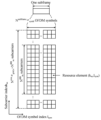
- FIG. 2 is a schematic diagram illustrating an example of a resource grid in a subframe according to an aspect of the present embodiment.
- 1 is a schematic block diagram showing a configuration of a terminal device 1 according to an aspect of the present embodiment.
- 1 is a schematic block diagram showing a configuration of a base station device 3 according to one aspect of the present embodiment.
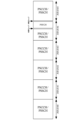
- FIG. 2 is a diagram illustrating an example of interlace mapping according to an aspect of this embodiment.
- FIG. 11 is a diagram illustrating an example of a case where a time domain for PSFCH is preset in a part of a COT according to an aspect of the present embodiment.
- FIG. 11 is a diagram illustrating a process of determining a priority for PSFCH transmission according to one aspect of the present embodiment.
- a and/or B may be a term including “A”, “B”, or "A and B”.
- a parameter or information indicating one or more values may mean that the parameter or information at least includes a parameter or information indicating the one or more values.
- the upper layer parameter may be a single upper layer parameter.
- the upper layer parameter may be an information element (IE) including multiple parameters.
- FIG. 1 is a conceptual diagram of a wireless communication system according to one aspect of this embodiment.
- the wireless communication system includes terminal devices 1A to 1C and a base station device 3 (gNB).
- terminal devices 1A to 1D are also referred to as terminal device 1 (UE).
- UE terminal device 1
- the base station device 3 may be configured to include one or both of an MCG (Master Cell Group) and an SCG (Secondary Cell Group).
- the MCG is a group of serving cells including at least a PCell (Primary Cell).
- the SCG is a group of serving cells including at least a PSCell (Primary Secondary Cell).
- the PCell is a cell on which an initial connection establishment procedure or a connection re-establishment procedure is performed by the terminal device 1.
- the PSCell is a serving cell on which a random access procedure is performed by the terminal device 1.
- the MCG may be configured to include one or more SCells (Secondary Cells).
- the SCG may be configured to include one or more SCells.
- the serving cell identity is a short identifier for identifying a serving cell.
- the serving cell identity may be given by an upper layer parameter.
- Serving cell group is a general term for MCG, SCG, and PUCCH cell group.
- a serving cell group may include one or more serving cells (or component carriers).
- One or more serving cells (or component carriers) included in a serving cell group may be operated by carrier aggregation.
- the base station device 3 communicates with the terminal device 1 using different frequency bands (carrier frequencies, frequency spectrums). This operation (multi-carrier operation) may be called carrier aggregation or dual connectivity. Different cells (serving cells) use different frequency bands. In the base station device 3 and the terminal device 1, the multiple cells used in carrier aggregation may be such that one cell uses the downlink frequency band and the uplink frequency band, and the other cells use only the downlink frequency band, or the other cells may also use the downlink frequency band and the uplink frequency band.
- the terminal device 1 makes an initial connection with the base station device 3, and after the connection with the base station device 3 is established, multiple cell connections are added. The terminal device 1 is added with a frequency band used for communication. The terminal device 1 is added with a cell (serving cell) used for communication. The terminal device 1 is added with a connection to the base station device 3.
- Terminal device 1A and terminal device 1B communicate directly using side link technology.
- Terminal device 1A and terminal device 1B are located within the coverage of base station device 3 (in-coverage).
- Terminal device 1A and terminal device 1C communicate directly using side link technology.
- Terminal device 1C and terminal device 1D communicate directly using side link technology.
- Terminal device 1C and terminal device 1D are located outside the coverage of base station device 3 (out-of-coverage). There are three cases: direct communication between in-coverage terminal devices 1, direct communication between in-coverage terminal device 1 and out-of-coverage terminal device 1, and direct communication between out-of-coverage terminal devices 1.
- the terminal device 1 and the base station device 3 may use one or more communication methods.
- CP-OFDM Cyclic Prefix-Orthogonal Frequency Division Multiplex
- DFT-s-OFDM Discrete Fourier Transform-spread-Orthogonal Frequency Division Multiplex
- DFT-s-OFDM is a communication method in which transform precoding is applied prior to signal generation in CP-OFDM.
- transformed precoding is also referred to as DFT precoding.
- CP-OFDM may be used for the side link between terminal device 1 and terminal device 1.
- DFT-s-OFDM may be used for the side link between terminal device 1 and terminal device 1.
- the base station device 3 may be configured with one transceiver device (or a transmission point, a transmitting device, a receiving point, a receiving device, a transceiver point).
- the base station device 3 may be configured to include multiple transceivers.
- each of the multiple transceivers may be located in a different geographical location.
- the subcarrier spacing setting ⁇ may represent any of 0, 1, 2, 3, or 4.
- the radio frame may be configured to include 10 subframes.
- the OFDM symbol is used as the unit of time domain for the communication method used in the wireless communication system.
- the OFDM symbol may be used as the unit of time domain for CP-OFDM.
- the OFDM symbol may also be used as the unit of time domain for DFT-s-OFDM.
- a slot may be composed of multiple OFDM symbols.
- one slot may be composed of Nslotsymb consecutive OFDM symbols.
- Nslotsymb 14.
- Nslotsymb 12.
- the slots may be indexed in the time domain.
- the slot index n ⁇ s may be given in ascending order as integer values ranging from 0 to Nsubframe, ⁇ slot-1 in the subframe.
- the slot index n ⁇ s,f may be given in ascending order as integer values ranging from 0 to Nframe, ⁇ slot-1 in the radio frame.
- FIG. 2 is a diagram showing an example of the configuration of a resource grid according to one aspect of this embodiment.
- the horizontal axis is the OFDM symbol index lsym
- the vertical axis is the subcarrier index ksc.
- the resource grid of FIG. 2 includes Nsize, ⁇ grid, x ⁇ NRBsc subcarriers, and Nsubframe, ⁇ symb OFDM symbols.
- Nsize, ⁇ grid, x indicate the bandwidth of the SCS-specific carrier.
- the values of Nsize, ⁇ grid, x are expressed in units of resource blocks.
- a resource identified by the subcarrier index ksc and the OFDM symbol index lsym is also called a resource element (RE: ResourceElement).
- a resource block (RB) contains NRBsc consecutive subcarriers.
- a BWP may be configured as a subset of a resource grid.
- a BWP set for a downlink is also referred to as a downlink BWP.
- a BWP set for an uplink is also referred to as an uplink BWP.
- the BWP set for a sidelink is also called a sidelink BWP.
- Carrier aggregation may be performing communication using multiple aggregated serving cells. Also, carrier aggregation may be performing communication using multiple aggregated component carriers. Also, carrier aggregation may be performing communication using multiple aggregated downlink component carriers. Also, carrier aggregation may be performing communication using multiple aggregated uplink component carriers.
- FIG. 3 is a schematic block diagram showing the configuration of a terminal device 1 according to one aspect of this embodiment.
- the terminal device 1 includes a radio transmission/reception unit 10 and an upper layer processing unit 14.
- the radio transmission/reception unit 10 includes at least an antenna unit 11, an RF (Radio Frequency) unit 12, and part or all of a baseband unit 13.
- the upper layer processing unit 14 includes at least a medium access control layer processing unit 15, and part or all of a radio resource control layer processing unit 16.
- the radio transmission/reception unit 10 is also referred to as a transmitting unit, a receiving unit, or a physical layer processing unit.
- the wireless transceiver unit 10 performs physical layer processing.
- the radio transceiver 10 may generate a baseband signal of an uplink physical channel.
- a transport block delivered from a higher layer on the UL-SCH may be placed on the uplink physical channel.
- the radio transceiver 10 may generate a baseband signal of an uplink physical signal.
- the wireless transceiver 10 may attempt to detect information transmitted by a downlink physical channel.
- a transport block of the information transmitted by the downlink physical channel may be delivered to a higher layer on DL-SCH.
- the wireless transceiver 10 may attempt to detect information transmitted by a downlink physical signal.
- the wireless transceiver unit 10 may generate a baseband signal of a sidelink physical channel.
- the wireless transceiver unit 10 may generate a baseband signal of a sidelink physical signal.
- the wireless transceiver unit 10 may attempt to detect information transmitted by the sidelink physical channel.
- the wireless transceiver unit 10 may attempt to detect information transmitted by the sidelink physical signal.
- the receiving unit of the terminal device 1 receives the PDCCH.
- the receiving processing unit of the terminal device 1 performs processing to receive the PDCCH in the downlink frequency band (cell, component carrier, carrier).
- the receiving processing unit of the terminal device 1 performs processing such as demodulation and decoding on the PDCCH.
- the receiving processing unit of the terminal device 1 performs processing to receive the PDCCH and detect downlink control information.
- the receiving unit of the terminal device 1 receives the PDSCH.
- the receiving processing unit of the terminal device 1 performs processing to receive the PDSCH in the downlink frequency band (cell, component carrier, carrier).
- the receiving processing unit of the terminal device 1 performs processing such as demodulation and decoding on the PDSCH.
- the receiving unit of the terminal device 1 receives the PSCCH.
- the receiving processing unit of the terminal device 1 performs processing such as demodulation and decoding on the PSCCH.
- the receiving processing unit of the terminal device 1 performs processing to receive the PSCCH and to detect side link control information.
- the receiving unit of the terminal device 1 determines the frequency resources (interlaces and resource blocks described later) that constitute the PSCCH.
- the receiving unit of the terminal device 1 determines the OFDM symbol in which the PSCCH may be placed.
- the receiving unit of the terminal device 1 blind decodes the PSCCH.
- the receiving unit of the terminal device 1 blind decodes the PSCCH in one slot in one resource pool.
- the receiving unit of the terminal device 1 may blind decode the PSCCH with two or more symbols (OFDM symbols) in one resource pool.
- the receiving unit of the terminal device 1 receives the PSSCH.
- the receiving processing unit of the terminal device 1 performs processing such as demodulation and decoding on the PSSCH.
- the receiving unit of the terminal device 1 receives the PSFCH.
- the receiving processing unit of terminal device 1 receives HARQ-ACK on the PSFCH.
- the transmitting unit (also referred to as the transmission processing unit) of the terminal device 1 transmits a HARQ-ACK.
- the transmitting processing unit of the terminal device 1 transmits a HARQ-ACK for the PDSCH.
- the transmitting processing unit of the terminal device 1 transmits a HARQ-ACK in the uplink frequency band (cell, component carrier, carrier).
- the transmission processing unit of the terminal device 1 transmits a HARQ-ACK for the PSSCH.
- the transmission processing unit of the terminal device 1 transmits a HARQ-ACK in the sidelink frequency band.
- the transmission processing unit of the terminal device 1 transmits a HARQ-ACK on the PSFCH.
- the transmission processing unit of the terminal device 1 may transmit a HARQ-ACK on the PSSCH.
- the transmission processing unit of the terminal device 1 may not transmit a HARQ-ACK for the PSSCH.
- the transmission processing unit of the terminal device 1 transmits a common interlaced signal in a time domain in which a PSFCH occasion (which may also be referred to as a PSFCH transmission occasion) is set.
- the common interlaced signal is a signal with an interlaced signal configuration.
- An interlaced signal is a signal arranged in resources distributed throughout the entire frequency band.
- the common interlaced signal is a common signal that can be transmitted by multiple terminal devices 1.
- the transmission processing unit of the terminal device 1 transmits a PSFCH in which a signal generated from HARQ-ACK information is arranged and a common interlaced signal in the same time domain.
- the signal generated from HARQ-ACK information and the common interlaced signal may be collectively defined as a PSFCH signal.
- the common interlaced signal is used for the purpose of satisfying the requirements of OCB.
- the resources in which the signal generated from the HARQ-ACK information is allocated are called Dedicated PRB(s) for PSFCH (Dedicated RB(s) for PSFCH).
- One dedicated PRB or multiple dedicated PRBs are used for one PSFCH.
- the number of dedicated PRBs used in one PSFCH is configured by the base station device 3 or configured in advance in the specifications.
- the number of PRBs constituting the dedicated PRB used in one PSFCH may be configured for each resource pool.
- the number of PRBs constituting the dedicated PRB used in one PSFCH may be configured for each sidelink BWP.
- Multiple resource blocks in one or more interlaces are indexed (numbered) as individual PRBs.
- An individual PRB is a unit of resources. Within one or more interlaces, indexing as individual PRBs is performed starting with the resource block with the smallest resource block index (lowest frequency) in the interlace with the smallest interlace index. After indexing as individual PRBs for all resource blocks in the interlace with the smallest interlace index, indexing as individual PRBs is performed starting with the resource block with the smallest resource block index (lowest frequency) in the interlace with the next largest interlace index. The above indexing of individual PRBs is performed for multiple resource blocks in one or more interlaces in which the PSFCH may be placed.
- the numbering for individual PRBs may be defined as follows: Numbering starts from the smallest index resource block in the smallest index interlace in the multiple interlaces in ascending order, then numbering continues for the next index resource block in the same interlace, numbering continues for the highest index resource block in the same interlace, numbering continues from the smallest index resource block in the next index interlace in ascending order in the same way, up to the highest index resource block in the highest index interlace.
- the numbering of resource blocks as individual PRBs is performed for multiple resource blocks of multiple interlaces excluding a common interlace (specific interlace).
- the numbering of resource blocks as individual PRBs is performed for resource blocks of multiple interlaces in a slot in which a PSFCH may be placed.
- the numbering of resource blocks as individual PRBs may be performed for resource blocks of multiple interlaces in a symbol in which a PSFCH may be placed.
- Information indicating a slot in which a PSFCH may be placed (such as a slot number or a slot period) is notified from the base station device 3 to the terminal device 1.
- the slot in which a PSFCH may be placed is set from the base station device 3 to the terminal device 1.
- Information indicating a symbol in which a PSFCH may be placed may be notified from the base station device 3 to the terminal device 1.
- the symbol in which a PSFCH may be placed may be set from the base station device 3 to the terminal device 1.
- the symbol in which a PSFCH may be placed may be set in advance from the base station device 3.
- the number of symbols (number of symbols) of PSFCH placed in one slot may be notified from the base station device 3 to the terminal device 1 and set.
- indexes and numbers may be interpreted as having the same meaning.
- Interlace #0 consists of PRB#0, PRB#10, PRB#20, PRB#30, PRB#40, PRB#50, PRB#60, PRB#70, PRB#80, and PRB#90.
- Interlace #1 consists of PRB#1, PRB#11, PRB#21, PRB#31, PRB#41, PRB#51, PRB#61, PRB#71, PRB#81, and PRB#91.
- Interlace #2 consists of PRB#2, PRB#12, PRB#22, PRB#32, PRB#42, PRB#52, PRB#62, PRB#72, PRB#82, and PRB#92.
- Interlace #3 consists of PRB#3, PRB#13, PRB#23, PRB#33, PRB#43, PRB#53, PRB#63, PRB#73, PRB#83, and PRB#93.
- Interlace #4 consists of PRB#4, PRB#14, PRB#24, PRB#34, PRB#44, PRB#54, PRB#64, PRB#74, PRB#84, and PRB#94.
- Interlace #5 consists of PRB#5, PRB#15, PRB#25, PRB#35, PRB#45, PRB#55, PRB#65, PRB#75, PRB#85, and PRB#95.
- Interlace #6 consists of PRB#6, PRB#16, PRB#26, PRB#36, PRB#46, PRB#56, PRB#66, PRB#76, PRB#86, and PRB#96.
- Interlace #7 consists of PRB#7, PRB#17, PRB#27, PRB#37, PRB#47, PRB#57, PRB#67, PRB#77, PRB#87, and PRB#97.
- Interlace #8 consists of PRB#8, PRB#18, PRB#28, PRB#38, PRB#48, PRB#58, PRB#68, PRB#78, PRB#88, and PRB#98.
- Interlace #9 consists of PRB#9, PRB#19, PRB#29, PRB#39, PRB#49, PRB#59, PRB#69, PRB#79, PRB#89, and PRB#99.
- interlace #0 is used as a common interlace.
- Different interlaces may be used as common interlaces.
- numbering as individual PRBs is performed starting from the smallest numbered PRB #1 of interlace #1 with the smallest number.
- PRB #1 is numbered as individual PRB #0
- PRB #11 is numbered as individual PRB #1
- PRB #21 is numbered as individual PRB #2
- PRB #31 is numbered as individual PRB #3
- PRB #41 is numbered as individual PRB #4
- PRB #51 is numbered as individual PRB #5
- PRB #61 is numbered as individual PRB #6
- PRB #71 is numbered as individual PRB #7
- PRB #81 is numbered as individual PRB #8, and PRB #91 is numbered as individual PRB #9.
- PRB#2 is numbered as individual PRB#10, PRB#12 as individual PRB#11, PRB#22 as individual PRB#12, PRB#32 as individual PRB#13, PRB#42 as individual PRB#14, PRB#52 as individual PRB#15, PRB#62 as individual PRB#16, PRB#72 as individual PRB#17, PRB#82 as individual PRB#18, and PRB#92 as individual PRB#19.
- PRB#3 is numbered as individual PRB#20, PRB#13 as individual PRB#21, PRB#23 as individual PRB#22, PRB#33 as individual PRB#23, PRB#43 as individual PRB#24, PRB#53 as individual PRB#25, PRB#63 as individual PRB#26, PRB#73 as individual PRB#27, PRB#83 as individual PRB#28, and PRB#93 as individual PRB#29.
- PRB#4 is numbered as individual PRB#30, PRB#14 as individual PRB#31, PRB#24 as individual PRB#32, PRB#34 as individual PRB#33, PRB#44 as individual PRB#34, PRB#54 as individual PRB#35, PRB#64 as individual PRB#36, PRB#74 as individual PRB#37, PRB#84 as individual PRB#38, and PRB#94 as individual PRB#39.
- PRB#5 is numbered as individual PRB#40, PRB#15 as individual PRB#41, PRB#25 as individual PRB#42, PRB#35 as individual PRB#43, PRB#45 as individual PRB#44, PRB#55 as individual PRB#45, PRB#65 as individual PRB#46, PRB#75 as individual PRB#47, PRB#85 as individual PRB#48, and PRB#95 as individual PRB#49.
- PRB#5 is numbered as individual PRB#40, PRB#15 as individual PRB#41, PRB#25 as individual PRB#42, PRB#35 as individual PRB#43, PRB#45 as individual PRB#44, PRB#55 as individual PRB#45, PRB#65 as individual PRB#46, PRB#75 as individual PRB#47, PRB#85 as individual PRB#48, and PRB#95 as individual PRB#49.
- PRB#6 is numbered as individual PRB#50, PRB#16 as individual PRB#51, PRB#26 as individual PRB#52, PRB#36 as individual PRB#53, PRB#46 as individual PRB#54, PRB#56 as individual PRB#55, PRB#66 as individual PRB#56, PRB#76 as individual PRB#57, PRB#86 as individual PRB#58, and PRB#96 as individual PRB#59.
- PRB#7 is numbered as individual PRB#60, PRB#17 as individual PRB#61, PRB#27 as individual PRB#62, PRB#37 as individual PRB#63, PRB#47 as individual PRB#64, PRB#57 as individual PRB#65, PRB#67 as individual PRB#66, PRB#77 as individual PRB#67, PRB#87 as individual PRB#68, and PRB#97 as individual PRB#69.
- PRB#8 is numbered as individual PRB#70, PRB#18 as individual PRB#71, PRB#28 as individual PRB#72, PRB#38 as individual PRB#73, PRB#48 as individual PRB#74, PRB#58 as individual PRB#75, PRB#68 as individual PRB#76, PRB#78 as individual PRB#77, PRB#88 as individual PRB#78, and PRB#98 as individual PRB#79.
- PRB#9 is numbered as individual PRB#80
- PRB#19 is numbered as individual PRB#81
- PRB#29 is numbered as individual PRB#82
- PRB#39 is numbered as individual PRB#83
- PRB#49 is numbered as individual PRB#84
- PRB#59 is numbered as individual PRB#85
- PRB#69 is numbered as individual PRB#86
- PRB#79 is numbered as individual PRB#87
- PRB#89 is numbered as individual PRB#88
- PRB#99 is numbered as individual PRB#89.
- the name of the number does not have to be an individual PRB#, but may be a different number name.
- the number may be named RB# for PSFCH.
- the base station device 3 transmits to the terminal device 1 information indicating the multiple resource blocks used for the PSFCH occasion for the multiple resource blocks numbered as above.
- the terminal device 1 receives from the base station device 3 information indicating the multiple resource blocks used for the PSFCH occasion for the multiple resource blocks numbered as above.
- the information indicating the multiple resource blocks used for the PSFCH occasion includes information indicating multiple individual PRBs.
- the information indicating the multiple resource blocks used in a PSFCH occasion may be information indicating the starting position (number of the starting individual PRB) of an individual PRB used in a PSFCH occasion and the number of individual PRBs.
- the terminal device 1 determines the configuration of the resource blocks used in a PSFCH occasion based on the information indicating the multiple resource blocks used in a PSFCH occasion.
- the terminal device 1 determines that a consecutive number of individual PRBs from the individual PRB at the starting position are used in a PSFCH occasion.
- the starting position of the individual PRB and the number of individual PRBs may be indicated in separate information fields.
- the combination of the starting position of the individual PRB and the number of individual PRBs may be indicated in correspondence with a specific value, a specific number, or a specific character string, etc., of the information indicating the multiple resource blocks used in a PSFCH occasion.
- the information indicating the multiple resource blocks used for a PSFCH occasion may consist of a bitmap for each individual PRB.
- the bitmap for each individual PRB is associated with the individual PRB with the smallest number, starting from the leftmost bit (LSB) of the bitmap.
- a bit value of 0 in the bitmap indicates that the individual PRB corresponding to that bit is not configured for the PSFCH occasion (not used for transmitting and receiving the PSFCH), and a bit value of 1 in the bitmap indicates that the individual PRB corresponding to that bit is configured for the PSFCH occasion (used for transmitting and receiving the PSFCH).
- the terminal device 1 determines the configuration of the resource blocks used for the PSFCH occasion based on the information indicating the multiple resource blocks used for the PSFCH occasion.
- the terminal device 1 determines that multiple individual PRBs with a bitmap bit value of 1 are used for the PSFCH occasion.
- the terminal device 1 determines one or more individual PRBs to be used for the PSFCH to be transmitted, arranges a signal generated from the information of the HARQ-ACK, and transmits it.
- the terminal device 1 determines one or more individual PRBs to be used for the PSFCH to be received, and demodulates the information of the HARQ-ACK from the signal received in the individual PRB.
- the terminal device 1 may determine one or more individual PRBs to be used for the PSFCH based at least on the index of the subchannel used for the transmitted one or more PSCCHs and/or PSSCHs.
- the terminal device 1 may determine one or more individual PRBs to be used for the PSFCH based at least on the index of the subchannel used for the received one or more PSCCHs and/or PSSCHs. For example, the terminal device 1 may determine one or more individual PRBs to be used for the PSFCH based at least on the index of the slot used for the transmitted one or more PSCCHs and/or PSSCHs. For example, the terminal device 1 may determine one or more individual PRBs to be used for the PSFCH based at least on the indexes of the slots used for one or more received PSCCHs and/or PSSCHs.
- the terminal device 1 uses only the individual PRBs within that 1 MHz bandwidth and does not use the PRBs included in the common interlace.
- the frequencies of the multiple individual PRBs used in one PSFCH can be separated, making it possible to avoid setting different transmission powers in different resource blocks in one PSFCH in order to satisfy the constraint of the maximum transmission power density within 1 MHz, and supporting efficient transmission.
- the transmission processing unit of the terminal device 1 transmits the PSCCH.
- the transmission processing unit of the terminal device 1 performs processing such as encoding and modulation on the PSCCH.
- the transmission processing unit of the terminal device 1 performs processing to transmit side link control information using the PSCCH.
- the transmission unit of the terminal device 1 determines the frequency resources (interlaces, resource blocks) that constitute the PSCCH.
- the transmission processing unit of the terminal device 1 determines the OFDM symbol in which the PSCCH can be placed.
- the transmission processing unit of the terminal device 1 transmits the PSSCH.
- the transmission processing unit of the terminal device 1 performs processing such as encoding and modulation on the PSSCH.
- the upper layer processing unit 14 outputs uplink data (transport blocks) generated by user operations, etc., to the wireless transceiver unit 10.
- the upper layer processing unit 14 processes the MAC layer, Packet Data Convergence Protocol (PDCP) layer, Radio Link Control (RLC) layer, and RRC layer.
- PDCP Packet Data Convergence Protocol
- RLC Radio Link Control
- RRC Radio Link Control
- the upper layer processing unit 14 outputs the side link data (transport block) to the radio transceiver unit 10.
- the media access control layer processing unit (MAC layer processing unit) 15 provided in the upper layer processing unit 14 performs MAC layer processing.
- the radio resource control layer processing unit 16 included in the upper layer processing unit 14 performs RRC layer processing.
- the radio resource control layer processing unit 16 manages various setting information/parameters (RRC parameters) of its own device.
- the radio resource control layer processing unit 16 sets various setting information/parameters (RRC parameters) based on upper layer signals received from the base station device 3. That is, the radio resource control layer processing unit 16 sets various setting information/parameters (RRC parameters) based on information indicating the various setting information/parameters (RRC parameters) received from the base station device 3.
- the setting information may include information related to processing or setting of physical channels and physical signals (i.e., the physical layer), the MAC layer, the PDCP layer, the RLC layer, and the RRC layer.
- the parameters may be upper layer parameters.
- the radio resource control layer processing unit 16 may acquire RRC parameters contained in an RRC message on a certain logical channel, and set the acquired RRC parameters in a memory area of the terminal device 1.
- the RRC parameters set in the memory area of the terminal device 1 may be provided to a lower layer.
- the radio resource control layer processing unit 16 sets a control resource set based on the RRC signaling received from the base station device 3.
- the radio resource control layer processing unit 16 sets (configures) a search area within the control resource set.
- the radio resource control layer processing unit 16 sets (configures) PDCCH candidates to be monitored within the control resource set.
- the radio resource control layer processing unit 16 sets (configures) the number of PDCCH candidates to be monitored within the control resource set.
- the radio resource control processing unit 16 sets (configures) the aggregation level of the PDCCH candidates to be monitored within the control resource set.
- the radio resource control layer processing unit 16 sets the DCI format to be monitored within the control resource set.
- the radio resource control layer processing unit 16 may set the DCI format to be monitored within the search area.
- the radio resource control layer processing unit 16 sets the DCI format to be monitored within the control resource set based on the RRC signaling indicated from the base station device 3.
- the radio resource control layer processing unit 16 may set the DCI format to be monitored within the search area based on the RRC signaling indicated from the base station device 3.
- the radio resource control layer processing unit 16 sets one or more DCI formats to be monitored in the reception processing unit.
- the radio resource control layer processing unit 16 performs settings related to multiple search areas. Each setting related to the multiple search areas is indexed.
- the radio resource control layer processing unit 16 performs settings related to CSI feedback (transmission of channel state information) based on the RRC signaling received from the base station device 3.
- the radio resource control layer processing unit 16 sets the CSI feedback transmission period, the CSI feedback transmission start timing (offset), the CSI feedback information type, and the like.
- the radio resource control layer processing unit 16 performs settings related to multiple CSI feedbacks.
- the settings related to multiple CSI feedbacks are each indexed.
- the radio resource control layer processing unit 16 performs settings related to the SPS based on the RRC signaling received from the base station device 3.
- the radio resource control layer processing unit 16 sets the period of the SPS resources (PDSCH resources), the start timing (offset) of the SPS resources (PDSCH resources), the number of HARQ processes set for the SPS, the offset used to derive the HARQ process ID used for the SPS, the RNTI value for scheduling the SPS, and the like.
- the radio resource control layer processing unit 16 performs settings related to multiple SPS. The settings related to multiple SPS are each indexed.
- the radio resource control layer processing unit 16 configures carrier aggregation based on the RRC signaling received from the base station device 3.
- the radio resource control layer processing unit 16 configures a serving cell (secondary cell, primary secondary cell) as the carrier aggregation configuration.
- the serving cell may be configured with a downlink component carrier.
- the serving cell may be configured with a downlink component carrier and an uplink component carrier.
- the radio resource control layer processing unit 16 controls the radio transmission/reception unit 10 to perform reception processing with the downlink component carrier configured in the carrier aggregation configuration.
- the radio resource control layer processing unit 16 controls the radio transmission/reception unit 10 to perform transmission processing with the uplink component carrier configured in the carrier aggregation configuration.
- the radio resource control layer processing unit 16 performs settings related to the side link based on the RRC signaling received from the base station device 3.
- the radio resource control layer processing unit 16 sets parameters related to the side link notified from the base station device 3. The parameters related to the side link will be described later.
- the radio resource control layer processing unit 16 sets an OFDM symbol in which the PSCCH can be placed.
- the radio resource control layer processing unit 16 sets a band in which the PSCCH can be placed.
- the radio resource control layer processing unit 16 sets the number of resource blocks or interlaces that constitute one PSCCH.
- the radio resource control layer processing unit 16 performs settings related to the transmission and reception of the PSCCH for the radio transmission and reception unit 10.
- the radio resource control layer processing unit 16 sets a slot (PSFCH occasion) in which the PSFCH can be transmitted.
- a slot in which the PSFCH can be transmitted is set every four slots.
- the radio resource control layer processing unit 16 sets multiple PRBs used for transmitting and receiving the PSFCH. For example, the radio resource control layer processing unit 16 sets multiple individual PRBs used for transmitting and receiving the PSFCH. For example, the radio resource control layer processing unit 16 sets multiple individual PRBs for a PSFCH occasion. For example, the radio resource control layer processing unit 16 sets the number of individual PRBs used for transmitting and receiving one PSFCH. For example, the radio resource control layer processing unit 16 sets the number of PSFCH occasions corresponding to one PSCCH/PSSCH. For example, the radio resource control layer processing unit 16 sets the number of candidate PSFCH occasions corresponding to one PSCCH/PSSCH transmission.
- the radio resource control layer processing unit 16 sets multiple individual PRBs for each of multiple candidate PSFCH occasions corresponding to one PSCCH/PSSCH transmission. For example, assume that four candidate PSFCH occasions (PSFCH occasion #0, PSFCH occasion #1, PSFCH occasion #2, PSFCH occasion #3) corresponding to one PSCCH/PSSCH transmission are set. A first set of multiple individual PRBs is set for PSFCH occasion #0, a second set of multiple individual PRBs is set for PSFCH occasion #1, a third set of multiple individual PRBs is set for PSFCH occasion #2, and a fourth set of multiple individual PRBs is set for PSFCH occasion #3.
- PSFCH occasion #1 For example, assume that two candidate PSFCH occasions (PSFCH occasion #0, PSFCH occasion #1) corresponding to one PSCCH/PSSCH transmission are set. A first set of multiple individual PRBs is set for PSFCH occasion #0, and a second set of multiple individual PRBs is set for PSFCH occasion #1.
- the medium access control layer processing unit (MAC layer processing unit) 15 activates/deactivates the secondary cell based on the MAC CE (MAC Control Element) received from the base station device 3.
- the medium access control layer processing unit (MAC layer processing unit) 15 outputs information indicating activation/deactivation for multiple serving cells configured by the radio resource control layer processing unit 16 to the radio transceiver unit 10 based on the MAC CE (SCell Activation/Deactivation MAC CEs) including information on activation/deactivation of the secondary cell.
- the medium access control layer processing unit (MAC layer processing unit) 15 deactivates the secondary cell based on a timer.
- the medium access control layer processing unit (MAC layer processing unit) 15 determines that scheduling has not been performed for a certain period of time by the base station device 3 for the serving cell by measuring with a timer, and deactivates the serving cell and controls the radio transceiver unit 10.
- the medium access control layer processing unit (MAC layer processing unit) 15 processes sidelink HARQ operations, sidelink scheduling requests, sidelink buffer status reports, and CSI reports.
- the radio resource control layer processing unit 16 may include functional information generated based on the functions of the terminal device 1 in an RRC message and transmit the information to the base station device 3.
- the wireless transceiver 10 performs modulation, encoding, and transmission processing.
- the wireless transceiver 10 generates a physical signal by encoding data (transport block), modulating it, and generating a baseband signal (converting it into a time-continuous signal), and transmits it to the base station device 3 or the terminal device 1.
- the wireless transceiver unit 10 performs demodulation, decoding, and reception processing.
- the wireless transceiver unit 10 outputs the transport block of the information detected based on the demodulation and decoding processing of the received physical signal to the upper layer processing unit 14 on the DL-SCH.
- the wireless transceiver unit 10 stops various reception processes and various transmission processes in the deactivated serving cell. For example, the wireless transceiver unit 10 stops monitoring the PDCCH in the deactivated serving cell. For example, the wireless transceiver unit 10 stops receiving the PDSCH in the deactivated serving cell. For example, the wireless transceiver unit 10 stops transmitting the SRS in the deactivated serving cell. For example, the wireless transceiver unit 10 stops transmitting the PUSCH in the deactivated serving cell.
- the RF unit 12 converts the signal received via the antenna unit 11 into a baseband signal (down-converts) and removes unnecessary frequency components.
- the RF unit 12 outputs the baseband signal to the baseband unit 13.
- the baseband unit 13 converts the analog signal input from the RF unit 12 into a digital signal.
- the baseband unit 13 removes the portion corresponding to the CP (Cyclic Prefix) from the converted digital signal.
- the baseband unit 13 performs a fast Fourier transform (FFT) on the signal from which the CP has been removed, and extracts the signal in the frequency domain.
- FFT fast Fourier transform
- the baseband unit 13 performs an inverse fast Fourier transform (IFFT) on the physical signal to generate an OFDM symbol.
- the baseband unit 13 adds a CP to the generated OFDM symbol to generate a baseband digital signal.
- the baseband unit 13 converts the baseband digital signal into an analog signal.
- the baseband unit 13 outputs the converted analog signal to the RF unit 12.
- IFFT inverse fast Fourier transform
- the RF unit 12 uses a low-pass filter to remove unnecessary frequency components from the analog signal input from the baseband unit 13, and upconverts the analog signal to a carrier frequency to generate an RF signal.
- the RF unit 12 transmits the RF signal via the antenna unit 11.
- the RF unit 12 also amplifies the power.
- the RF unit 12 may also have a function of controlling the transmission power.
- the RF unit 12 is also referred to as a transmission power control unit.
- the wireless transceiver 10 performs carrier sensing (LBT) before transmitting a signal in order to avoid collision of signals with other devices.
- LBT carrier sensing
- Type 1 LBT with a random backoff process using a variable-sized contention window
- Type 2A LBT with no random backoff process
- Type 2B LBT with no random backoff process
- ⁇ Type 2C LBT not performed
- the wireless transceiver 10 transmits a signal after detecting in listening that no other devices are transmitting (idle state), and does not transmit a signal when detecting in listening that other devices are transmitting (busy state).
- the wireless transceiver 10 acquires a transmission opportunity and transmits when the LBT result is idle, and does not transmit when the LBT result is busy.
- the time of the transmission opportunity is called the Channel Occupancy Time (COT).
- COT Channel Occupancy Time
- the terminal device 1 monitors the channel before transmitting data, evaluates the idle channel, and transmits data only when it is confirmed that the channel is in an idle state.
- the wireless transmission/reception unit 10 When performing a random backoff process, the wireless transmission/reception unit 10 randomly generates a backoff counter value within the range of the contention window size after the previous transmission. In random backoff, the terminal device 1 evaluates whether the channel is idle by detecting channel energy at each time interval using the random backoff counter. The wireless transmission/reception unit 10 waits until it is confirmed that the channel is idle for a certain period of time, and performs carrier sense (sensing) for each sensing slot time. If the result of the carrier sense shows that the channel is idle, the wireless transmission/reception unit 10 decreases the backoff counter value.
- the wireless transmission/reception unit 10 maintains the backoff counter value, waits until it is confirmed that the channel is idle for a certain period of time, and then performs carrier sense. After repeating the above operations, the wireless transmission/reception unit 10 obtains access to the channel after the backoff counter value becomes zero, and can start transmitting signals on that channel.
- the radio transceiver unit 10 updates the contention window size based on the status of the HARQ-ACK.
- the radio transceiver unit 10 sets the contention window size to the minimum value.
- the radio transceiver unit 10 sets the contention window size to the next largest value.
- the radio transceiver unit 10 continues to use the maximum value even when the status of the HARQ-ACK is NACK.
- the radio transceiver unit 10 may set (reset) the contention window size to the minimum value. The predetermined number of times may be set from the base station device 3 to the terminal device 1.
- the initial value of the random backoff counter may be an integer between 0 and the contention window size. Before the random backoff counter is initialized, the contention window size is adjusted to control the average time required for terminal device 1 to access the channel.
- the terminal device 1 performs a listen-before-talk (LBT) on the channel before transmitting on the channel.
- the terminal device 1 may adjust the time interval (amount of time) for which the LBT is performed.
- the terminal device 1 may select a random number between zero and the contention window size. If the channel is free for at least the time interval associated with the selected random number, the terminal device 1 gets a transmission opportunity and can transmit.
- LBT listen-before-talk
- FIG. 4 is a schematic block diagram showing the configuration of a base station device 3 according to one aspect of this embodiment.
- the base station device 3 includes a radio transmission/reception unit 30 and a higher layer processing unit 34.
- the radio transmission/reception unit 30 includes an antenna unit 31, an RF (Radio Frequency) unit 32, and a baseband unit 33.
- the higher layer processing unit 34 includes a medium access control layer processing unit 35 and a radio resource control layer processing unit 36.
- the radio transmission/reception unit 30 is also referred to as a transmitting unit, a receiving unit, or a physical layer processing unit.
- the upper layer processing unit 34 processes the MAC (Medium Access Control) layer, the Packet Data Convergence Protocol (PDCP) layer, the Radio Link Control (RLC) layer, and the Radio Resource Control (RRC) layer.
- MAC Medium Access Control
- PDCP Packet Data Convergence Protocol
- RLC Radio Link Control
- RRC Radio Resource Control
- the MAC layer is also referred to as the MAC sublayer.
- the PDCP layer is also referred to as the PDCP sublayer.
- the RLC layer is also referred to as the RLC sublayer.
- the RRC layer is also referred to as the RRC sublayer.
- the medium access control layer processing unit 35 provided in the upper layer processing unit 34 performs MAC layer processing.
- the MAC layer processing may include mapping between logical channels and transport channels, multiplexing one or more MAC SDUs (Service Data Units) into transport blocks, decomposing a transport block delivered from the physical layer on the UL-SCH into one or more MAC SDUs, applying HARQ (Hybrid Automatic Repeat reQuest) to the transport block, and some or all of the processing of scheduling requests.
- MAC SDUs Service Data Units
- HARQ Hybrid Automatic Repeat reQuest
- the radio resource control layer processing unit 36 included in the upper layer processing unit 34 performs RRC layer processing.
- the RRC layer processing may include some or all of the management of broadcast signals, management of RRC connection/RRC idle states, and RRC reconfiguration.
- the radio resource control layer processing unit 36 generates downlink data (transport blocks), system information, RRC messages, MAC CE, etc. that are placed in the PDSCH, or obtains them from the upper node, and outputs them to the radio transceiver unit 30.
- the radio resource control layer processing unit 36 also manages various setting information/parameters (RRC parameters) for each terminal device 1.
- the radio resource control layer processing unit 36 may set various setting information/parameters for each terminal device 1 via a higher layer signal. That is, the radio resource control layer processing unit 36 transmits/reports information indicating various setting information/parameters.
- the setting information may include information related to processing or setting of a physical channel or physical signal (i.e., the physical layer), the MAC layer, the PDCP layer, the RLC layer, and the RRC layer.
- the parameters may be higher layer parameters.
- the radio resource control layer processing unit 36 may include the RRC parameters in an RRC message on a certain logical channel and transmit it to the terminal device 1.
- the RRC message may be mapped to any one of the BCCH (Broadcast Control CHannel), CCCH (Common Control CHannel), and DCCH (Dedicated Control CHannel).
- the radio resource control layer processing unit 36 may determine the RRC parameters to be transmitted to the terminal device 1 based on the RRC parameters included in the RRC message transmitted from the terminal device 1.
- the RRC message transmitted from the terminal device 1 may be related to a functional information report of the terminal device 1.
- the radio resource control layer processing unit 36 sets a control resource set for the terminal device 1. Multiple PDCCH candidates are configured (set) within the set control resource set.
- the radio resource control layer processing unit 36 sets a search space for the terminal device 1.
- the radio resource control layer processing unit 36 sets a DCI format to be monitored in the search space for the terminal device 1.
- the radio resource control layer processing unit 36 sets the DCI format to be applied to the terminal device 1 within the control resource set.
- the radio resource control layer processing unit 36 generates RRC signaling indicating the DCI format to be applied to the terminal device 1.
- the radio resource control layer processing unit 36 sets one or more DCI formats to be applied in the transmission processing unit.
- the radio resource control layer processing unit 36 performs settings related to multiple search areas. Each setting related to the multiple search areas is indexed.
- the radio resource control layer processing unit 36 sets resources for transmitting HARQ-ACK to the terminal device 1.
- the radio resource control layer processing unit 36 sets resources for transmitting HARQ-ACK for PDSCH in the downlink frequency band (cell, component carrier, carrier).
- the radio resource control layer processing unit 36 sets resources for transmitting HARQ-ACK for PDSCH in the uplink frequency band (cell, component carrier, carrier).
- the radio resource control layer processing unit 36 performs settings related to CSI feedback (transmission of channel state information) for the terminal device 1.
- the radio resource control layer processing unit 36 sets the CSI feedback transmission period, the CSI feedback transmission start timing (offset), the CSI feedback information type, and the like.
- the radio resource control layer processing unit 36 performs settings related to multiple CSI feedbacks. Each of the settings related to multiple CSI feedbacks is indexed.
- the radio resource control layer processing unit 36 performs settings related to SPS for the terminal device 1.
- the radio resource control layer processing unit 36 sets the period of the SPS resources (PDSCH resources), the start timing (offset) of the SPS resources (PDSCH resources), the number of HARQ processes set for the SPS, the offset used to derive the HARQ process ID used for the SPS, the RNTI value for scheduling the SPS, and the like.
- the radio resource control layer processing unit 36 performs settings related to multiple SPS. The settings related to multiple SPS are each indexed.
- the radio resource control layer processing unit 36 configures carrier aggregation for the terminal device 1.
- the radio resource control layer processing unit 36 configures a serving cell (secondary cell, primary secondary cell) as the carrier aggregation configuration.
- the serving cell may be configured with a downlink component carrier.
- the serving cell may be configured with a downlink component carrier and an uplink component carrier.
- the radio resource control layer processing unit 36 controls the radio transmission/reception unit 30 to perform transmission processing for the terminal device 1 using the downlink component carrier configured in the carrier aggregation configuration.
- the radio resource control layer processing unit 36 controls the radio transmission/reception unit 30 to perform reception processing for the terminal device 1 using the uplink component carrier configured in the carrier aggregation configuration.
- the radio resource control layer processing unit 36 performs settings related to the side link for the terminal device 1.
- the radio resource control layer processing unit 36 sets parameters related to the side link for the terminal device 1 and notifies the terminal device 1 via the radio transceiver unit 30. For example, the following information is used as the parameters related to the side link. - Configuring Sidelink BWP - Configuring Sidelink Radio Bearer - Configuring Sidelink Measurements
- the information indicating the sidelink BWP configuration includes information indicating the starting position of the symbol in the slot used for the sidelink, the symbol length, the PSBCH configuration, the sidelink resource pool configuration, etc.
- the information indicating the PSBCH configuration includes information indicating parameters used for PSBCH transmission power control.
- the information indicating the sidelink resource pool configuration includes information indicating the sidelink receiving resource pool configuration, the sidelink transmitting resource pool configuration, etc.
- the sidelink transmission resource pool configuration includes the transmission resource pool configuration for the method (mode 1) in which the base station device 3 indicates scheduling information to the terminal device 1, and the transmission resource pool configuration for the method (mode 2) in which the terminal device 1 autonomously selects resources.
- the information indicating the sidelink resource pool configuration includes information indicating the PSCCH configuration, information indicating the PSSCH configuration, information indicating the PSFCH configuration, information indicating the sidelink subchannel size, information indicating the start position of the sidelink subchannel, information indicating the MCS table used in the sidelink, information indicating the sidelink PTRS configuration, information indicating the sidelink TDD UL-DL configuration, information indicating the number of PRBs in the sidelink resource pool, information indicating the time resources in the sidelink resource pool, information indicating parameters of the sidelink transmit power control, information indicating the maximum number of reserved PSCCH/PSSCH resources that can be indicated in one SCI, information indicating the set of reservable resource intervals, information indicating whether the PSCCH or PSSCH DM RS is used for L1 RSRP measurement in the sensing operation, information indicating the start position of the sensing window, information indicating the end position of the sensing window, information indicating the sidelink synchronization configuration, etc.
- the information indicating the configuration of the sidelink resource pool may include information indicating the slot configuration. It may include information indicating whether a slot configuration with one symbol (OFDM symbol) in which the PSCCH can be placed within the slot or a slot configuration with two symbols in which the PSCCH can be placed within the slot is applied. In the slot configuration with one symbol in which the PSCCH can be placed within the slot, it is configured in which of the first symbol, second symbol, third symbol, fourth symbol, fifth symbol, sixth symbol, or seventh symbol the PSCCH can be placed.
- the first symbol in which the PSCCH can be placed is any one of the first, second, third, fourth, fifth, sixth, or seventh symbols
- the second symbol in which the PSCCH can be placed is any one of the fourth, fifth, sixth, seventh, or eighth symbols.
- the information indicating the slot configuration may indicate a symbol in which a signal for AGC can be placed.
- a signal for AGC may be placed before the PSCCH.
- PSSCH is placed in the OFDM symbol following the OFDM symbol in which PSCCH is placed. For example, if PSCCH is placed in the first symbol of a slot, PSSCH is placed in the second or subsequent symbols in the slot. For example, if PSCCH is placed in the eighth symbol of a slot, PSSCH is placed in the ninth or subsequent symbols in the slot.
- the information indicating the configuration of the PSCCH includes information indicating the number of symbols in the PSCCH, information indicating the number of RBs that make up the PSCCH, information indicating the initial value (ID) of the scrambling of the DM RS of the PSCCH, and information indicating the number of bits reserved in the first stage SCI.
- the information indicating the configuration of the PSSCH includes information indicating candidates for ⁇ offsets used to determine the number of coded modulation symbols in the 2nd stage SCI, information indicating the time domain pattern of the DM RS of the PSSCH, and information indicating a scaling factor for limiting the number of resource elements assigned to the 2nd stage SCI of the PSSCH.
- the information indicating the configuration of the PSFCH includes information indicating the set of PRBs used for transmitting and receiving the PSFCH, information indicating the number of cyclic shift pairs used for PSFCH transmission that can be multiplexed onto one PRB, information indicating the number of PSFCH resources available for multiplexing HARQ-ACK information, information indicating a scrambling ID for sequence hopping of the PSFCH, information indicating the interval of the PSFCH resources, and information indicating the minimum time gap between the PSSCH and the PSFCH.
- a bitmap is used as the information indicating the set of PRBs used for transmitting and receiving the PSFCH, and each bit indicates whether the PRB corresponding to the bit position is included in the set of PRBs used for transmitting and receiving the PSFCH.
- the information indicating the interval of the PSFCH resources is information indicating the interval of the slots (PSFCH occasions) in which the PSFCH resources are arranged. For example, information indicating an interval of one slot, an interval of two slots, or an interval of four slots is used.
- the information indicating the configuration of the PSFCH includes information indicating a set of individual PRBs used for transmitting and receiving the PSFCH (PSFCH occasion). For example, when interlacing is used in an unlicensed band, information indicating an individual PRB used for transmitting and receiving the PSFCH (PSFCH occasion) is included.
- the information indicating the set of individual PRBs used for the PSFCH occasion may be information indicating the starting position (number of the starting individual PRB) of the individual PRBs used for the PSFCH occasion and the number of individual PRBs.
- the information indicating the set of individual PRBs used for the PSFCH occasion may be a bitmap consisting of a bit for each individual PRB.
- the information indicating the set of individual PRBs used for transmitting and receiving the PSFCH (PSFCH occasion) may be configured for each sidelink BWP or for each resource pool (transmission resource pool, reception resource pool).
- the information indicating the set of individual PRBs used in the PSFCH occasion may include information indicating a symbol number (information indicating a symbol).
- the terminal device 1 determines that an individual PRB to be used in the PSFCH occasion is configured for the symbol with the indicated number.
- the information indicating the configuration of the PSFCH includes information indicating the number of individual PRBs used for one PSFCH.
- One individual PRB or multiple individual PRBs are used for one PSFCH.
- Information indicating the number of individual PRBs used for one PSFCH may be configured for each resource pool (transmission resource pool, reception resource pool).
- the information indicating the PSFCH configuration includes information indicating the number of PSFCH occasions corresponding to one PSCCH/PSSCH.
- the information indicating the PSFCH configuration may include information indicating the number of candidate PSFCH occasions corresponding to one PSCCH/PSSCH transmission.
- the information indicating the PSFCH configuration may include information indicating a plurality of individual PRBs for each of a plurality of candidate PSFCH occasions corresponding to one PSCCH/PSSCH transmission.
- the information indicating the PSFCH configuration may include information indicating a plurality of individual PRBs and symbols for each of a plurality of candidate PSFCH occasions corresponding to one PSCCH/PSSCH transmission.
- the information indicating the parameters of the sidelink transmission power control includes information indicating the parameters used for the transmission power control based on the sidelink path loss and information indicating the parameters used for the transmission power control based on the downlink path loss.
- the information indicating the sidelink synchronization configuration includes information indicating whether the sidelink synchronization configuration is used for transmitting and receiving the sidelink synchronization signal when the terminal device 1 is synchronized to the GNSS, or whether the sidelink synchronization configuration is used for transmitting and receiving the sidelink synchronization signal when the terminal device 1 is synchronized to the base station device 3, information indicating the type of hysteresis when evaluating the terminal device 1 for synchronization reference, information indicating the number of sidelink SSB transmissions in one sidelink SSB section, information indicating the section and starting position of the sidelink SSB, information indicating the ID of the sidelink synchronization signal, information indicating the threshold used to determine the transmission of the sidelink synchronization signal, etc.
- the information indicating the configuration of the sidelink radio bearer includes information indicating whether the terminal device 1 is the synchronization source, information indicating parameters used to detect a sidelink radio link failure, information indicating the frequency used by the sidelink, information indicating the configuration for the method (mode 1) in which the base station device 3 indicates scheduling information to the terminal device 1, information indicating the configuration for the method (mode 2) in which the terminal device 1 autonomously selects resources, information indicating whether CSI reporting is used, information indicating the configuration of the sidelink scheduling request, information indicating the priority of transmission and reception of the sidelink SSB, information indicating the RLC mode, information indicating the configuration of the sidelink logical channel, information indicating the configuration of the sidelink RLC, etc.
- the information indicating the frequency at which the sidelink is used further includes information indicating the subcarrier spacing, information indicating the frequency position of the sidelink SSB, information indicating the synchronization priority, etc.
- the information indicating the configuration for the method (mode 1) in which the base station device 3 instructs the terminal device 1 about scheduling information includes information indicating the RNTI used by the base station device 3 to scramble the CRC of a DCI format (e.g., DCI format 3_0) including scheduling information for the terminal device 1, information indicating the configuration of the sidelink MAC, and information indicating the configuration of the sidelink Configured Grant.
- the information indicating the configuration of the sidelink MAC includes information indicating the configuration of the sidelink BSR and information indicating a threshold used to determine the priority of sidelink transmission and uplink transmission.
- the information indicating the configuration of the Sidelink Configured Grant includes information indicating an ID for identifying the Sidelink Configured Grant, information indicating the frequency resource of the Sidelink Configured Grant, information indicating the time resource of the Sidelink Configured Grant, information indicating the HARQ process ID of the Sidelink Configured Grant, information indicating the resources used for the Sidelink HARQ-ACK transmission, information indicating the duration of the Sidelink Configured Grant, information indicating the resource pool to which the Sidelink Configured Grant is applied, information indicating the starting subchannel of the Sidelink Configured Grant, etc.
- the information indicating the configuration for the method (mode 2) in which the terminal device 1 autonomously (automatically) selects resources includes information indicating PSSCH transmission parameters such as MCS, subchannel number, number of retransmissions, and transmission power parameters, information indicating the probability of being used in resource selection, and information indicating the threshold value for RSRP used in resource selection.
- Information indicating the number of slots (multiple slots) used in one unit of transmission is included in the parameters related to the side link.
- Information indicating the number of consecutive slots is included in the information indicating the parameters related to the side link.
- Information indicating a time length such as ms (milliseconds) may be included instead of the number of slots.
- Information indicating the number of slots used in one unit of transmission in mode 2 is included.
- the terminal device 1 performs resource selection in units of the indicated number of slots.
- the terminal device 1 reserves resources in units of the indicated number of slots.
- Information indicating the number of slots used in one unit of transmission is used (set, configured) for each resource pool.
- a resource of multiple logically consecutive slots used in one unit of transmission is called a multiple slot resource (multiple resource unit).
- the length of the consecutive slots corresponds to, for example, the maximum COT.
- information indicating the number of slots corresponding to a consecutive slot length of 2 ms, 3 ms, 4 ms, 6 ms, 8 ms, or 10 ms is set for the resource pool.
- the number of slots used in one unit of transmission is indicated as 2 slots, 3 slots, 4 slots, 6 slots, 8 slots, or 10 slots.
- the terminal device 1 may determine (interpret) the number of slots used in one unit of transmission based on the subcarrier spacing used from the information indicating the number of slots used in one unit of transmission.
- the terminal device 1 selects resources and reserves resources in units of 2 slots. For example, the terminal device 1 selects resources for certain 2 slots and reserves two sets of resources for different 2 slots. For example, the terminal device 1 selects resources for certain 2 slots and reserves one set of resources for different 2 slots. For example, when the information indicating the number of slots used in one unit of transmission indicates 3 slots, the terminal device 1 selects resources and reserves resources in units of 3 slots. For example, the terminal device 1 selects resources for certain 3 slots and reserves two sets of resources for different 3 slots. For example, the terminal device 1 selects resources for certain 3 slots and reserves one set of resources for different 3 slots.
- the terminal device 1 selects resources and reserves resources in units of 4 slots. For example, the terminal device 1 selects resources for certain 4 slots and reserves two sets of resources for different 4 slots. For example, the terminal device 1 selects a resource of 4 slots and reserves one set of resources of different 4 slots. For example, when information indicating the number of slots used in one unit of transmission indicates 6 slots, the terminal device 1 performs resource selection and resource reservation in units of 6 slots. For example, the terminal device 1 selects a resource of 6 slots and reserves two sets of resources of different 6 slots. For example, the terminal device 1 selects a resource of 6 slots and reserves one set of resources of different 6 slots.
- the terminal device 1 when information indicating the number of slots used in one unit of transmission indicates 8 slots, the terminal device 1 performs resource selection and resource reservation in units of 8 slots. For example, the terminal device 1 selects a resource of 8 slots and reserves two sets of resources of different 8 slots. For example, the terminal device 1 selects a resource of 8 slots and reserves one set of resources of different 8 slots. For example, when information indicating the number of slots used in one unit of transmission indicates 10 slots, the terminal device 1 performs resource selection and resource reservation in units of 10 slots. For example, terminal device 1 selects a 10-slot resource and reserves two different sets of 10-slot resources. For example, terminal device 1 selects a 10-slot resource and reserves one different set of 10-slot resources.
- a time interval (resource reservation interval) between the first selected set of resources and the next reserved set of resources is set for each resource pool.
- the base station device 3 transmits RRC signaling including a parameter indicating the time interval to the terminal device 1.
- the terminal device 1 receives RRC signaling including a parameter indicating the time interval from the base station device 3.
- the time interval is also used as the time interval between the reserved sets of resources.
- the terminal device 1 may select a channel access priority class according to the priority of the data to be transmitted, determine the maximum COT to be used in the selected channel access priority class, select a resource pool in which the number of slots to be used in one unit of transmission set for the resource pool corresponds to the maximum COT, and select and reserve resources in units of multiple slots. Multiple resource pools are configured for the terminal device 1, and for each of the configured resource pools, a different number of consecutive slots are set as slots to be used in one unit of transmission in mode 2.
- the channel access priority class for the resource pool is included in the parameters.
- the number of slots used in one unit of transmission for each channel access priority class may be predefined, and the number of slots used in one unit of transmission set for each resource pool may be implicitly notified from the base station device 3 to the terminal device 1.
- the terminal device 1 recognizes the number of slots used in one unit of transmission in mode 2 in the resource pool from the channel access priority class set for that resource pool.
- Multiple slot resources may also be used in mode 1.
- a guard time (also called a gap) is provided in the last time interval of the slot. Switching between transmission and reception occurs during the guard time.
- guard times are not provided in some slots.
- guard times of short duration (16 ⁇ s or less) during which LBT is not required may be provided in some slots. For example, when a resource of two consecutive slots is used as a multiple slot resource, a guard time is not provided in the last time interval of the first slot. For example, when a resource of three consecutive slots is used as a multiple slot resource, a guard time is not provided in the last time interval of the first slot and the second slot.
- a guard time is not provided in the last time interval of the first slot, the second slot, and the third slot.
- no guard time is provided in the last time interval of each of the first, second, third, fourth, and fifth slots.
- no guard time is provided in the last time interval of each of the first, second, third, fourth, fifth, sixth, and seventh slots.
- no guard time is provided in the last time interval of each of the first, second, third, fourth, fifth, sixth, seventh, eighth, and ninth slots.
- the terminal device 1 transmits one channel or multiple channels in multiple consecutive slots. For example, the terminal device 1 transmits one PSSCH spanning multiple slots. Note that a separate transport block is transmitted in each slot. For example, the terminal device 1 transmits a separate PSSCH in each slot in multiple slots. For example, the terminal device 1 transmits a separate PSCCH in each slot in multiple slots. Note that in this case, the PSCCH in each slot corresponds to the PSSCH in each slot. Note that when one PSSCH is transmitted across multiple slots, the corresponding PSCCH may be transmitted only in the first slot of the multiple consecutive slots.
- the PSSCH includes information indicating the number of slots used in one unit of transmission. Alternatively, the PSCCH includes information indicating the number of remaining slots (the number of remaining slots belonging to a multiple resource unit) in the multiple slots from which resources are selected.
- the terminal device 1 recognizes resources (resources of multiple consecutive slots) secured in other terminal devices 1 from the information (1st SCI information) contained in the received PSCCH, excludes those resources, and selects and reserves resources to be used by the terminal device 1 from resources that were not recognized as secured in other terminal devices 1.
- the terminal device 1 may also recognize resources (resources of multiple consecutive slots) secured or reserved in other terminal devices 1 from the information of the 2nd SCI contained in the received PSSCH.
- terminal device 1 selecting and reserving resources in units of multiple consecutive slots corresponding to the maximum COT, the number of LBTs can be reduced and efficient mode 2 operation can be achieved.
- resources are selected and reserved in slot units and there is a time gap between slots (a gap of 16 ⁇ s or more)
- terminal device 1 needs to perform an LBT before transmitting each slot. If the LBT fails, terminal device 1 cannot transmit, and an increase in the number of LBTs leads to an increase in the number of LBT failures, leading to an increase in the number of times terminal device 1 cannot transmit.
- the number of LBTs can be reduced and efficient operation can be achieved.
- Information indicating the number of slots used in one unit of transmission may not be notified from the base station device 3 to the terminal device 1 as a parameter related to the side link, but may be preconfigured for resource pools with different numbers of slots used in one unit of transmission.
- a resource pool in which the number of slots used in one unit of transmission is preconfigured may be used between out-of-coverage terminal devices 1.
- a resource pool in which the number of slots used in one unit of transmission in mode 2 is 2 may be preconfigured.
- a resource pool in which the number of slots used in one unit of transmission in mode 2 is 3 may be preconfigured.
- a resource pool in which the number of slots used in one unit of transmission in mode 2 is 4 may be preconfigured.
- a resource pool in which the number of slots used in one unit of transmission in mode 2 is 6 may be preconfigured.
- a resource pool in which the number of slots used in one unit of transmission in mode 2 is 8 may be preconfigured.
- a resource pool in which the number of slots used in one unit of transmission in mode 2 is 10 may be preconfigured.
- Terminal device 1 selects a resource pool according to the priority of the data to be transmitted, and selects and reserves resources in units of multiple slots.
- the information indicating the configuration of the sidelink logical channel includes information indicating the sidelink logical channel priority, information indicating the configuration of the scheduling request applicable to the sidelink logical channel, information indicating the bit rate, information indicating the sidelink bucket size interval, information indicating whether to apply HARQ feedback to the sidelink logical channel, information indicating the subcarrier spacing applied to the resource to which the sidelink logical channel is mapped, information indicating the maximum physical channel interval of the resource to which the sidelink logical channel is mapped, information indicating the ID of the sidelink logical channel group, etc.
- the information indicating the configuration of the sidelink measurement includes information indicating the frequency at which the sidelink measurement is performed, information indicating the filter coefficient applied to the sidelink measurement, information indicating the interval at which the sidelink measurement results are reported, information indicating the threshold used to decide whether to report the sidelink measurement results, information indicating the interval used to decide whether to report the sidelink measurement results, etc.
- Sidelink RRC signaling includes information indicating the delay time limit for sidelink CSI reporting.
- the information indicating the delay time limit for sidelink CSI reporting indicates the limit of the delay time from triggering of sidelink CSI to reporting in slot units.
- the sidelink RRC signaling includes information indicating the configuration of the sidelink CSI-RS.
- the information indicating the configuration of the sidelink CSI-RS includes information indicating the frequency location of the sidelink CSI-RS and information indicating the first location of the sidelink CSI-RS within a slot.
- the information indicating the frequency location of the sidelink CSI-RS indicates the number of antenna ports (one or two) used for sidelink CSI-RS transmission, and indicates the subcarrier on which the CSI-RS is located for each antenna port.
- the terminal device 1 receives the above RRC signaling (RRC parameters).
- the radio resource control layer processing unit 16 of the terminal device 1 manages the information contained in the RRC signaling, sets various parameters, and controls the processing of each unit.
- the terminal device 1 notifies the base station device 3 of information related to the sidelink by RRC signaling.
- the information includes information indicating the frequencies at which the terminal device 1 is interested in receiving sidelink communications, information indicating the frequencies at which the terminal device 1 is interested in transmitting sidelink communications, information indicating parameters for requesting sidelink transmission resources, information about sidelink capabilities, information indicating the cast type (broadcast, groupcast, unicast) for which sidelink resources are requested, information indicating the destination identity, information about sidelink QoS, information indicating the RLC mode, and information indicating a list of synchronization references used by the terminal device 1.
- Information regarding sidelink capabilities includes information indicating the number of PSFCHs that can be transmitted simultaneously and information indicating the number of PSFCHs that can be received simultaneously.
- the information indicating the number of PSFCHs that can be transmitted simultaneously indicates any one of 4, 8, or 16.
- the information indicating the number of PSFCHs that can be received simultaneously indicates any one of 5, 15, 25, 32, 35, 45, 50, or 64.
- the media access control layer processing unit (MAC layer processing unit) 35 generates MAC CEs (SCell Activation/Deactivation MAC CEs) that instruct the activation/deactivation of secondary cells.
- the media access control layer processing unit (MAC layer processing unit) 35 generates MAC CEs that instruct the activation/deactivation of secondary cells for multiple serving cells configured by the radio resource control layer processing unit 36.
- the media access control layer processing unit (MAC layer processing unit) 35 deactivates secondary cells based on a timer.
- the media access control layer processing unit (MAC layer processing unit) 35 determines that scheduling has not been performed for a certain period of time for a serving cell by measuring with a timer, deactivates the serving cell, and controls the radio transceiver unit 30.
- the functions of the wireless transceiver unit 30 are similar to those of the wireless transceiver unit 10, and therefore a description thereof will be omitted where appropriate.
- the wireless transceiver unit 30 performs physical layer processing.
- the physical layer processing may include some or all of the following: generation of a baseband signal for a physical channel, generation of a baseband signal for a physical signal, detection of information transmitted by the physical channel, and detection of information transmitted by the physical signal.
- the physical layer processing may include a mapping process of a transport channel to a physical channel.
- the baseband signal is also referred to as a time-continuous signal.
- the wireless transceiver 30 may perform one or both of demodulation and decoding processes.
- the wireless transceiver 30 may deliver a transport block of the information detected based on the demodulation and decoding processes of the received physical signal to a higher layer on the UL-SCH.
- the wireless transceiver 30 may generate a baseband signal of a downlink physical channel.
- the transport block delivered from a higher layer on the DL-SCH may be placed in the downlink physical channel.
- the wireless transceiver 30 may generate a baseband signal of a downlink physical signal.
- the wireless transceiver 30 may perform some or all of the modulation process, the encoding process, and the transmission process.
- the wireless transceiver 30 may generate a physical signal based on some or all of the encoding process, the modulation process, and the baseband signal generation process for the transport block.
- the wireless transceiver 30 may place the physical signal in a certain BWP.
- the wireless transceiver 30 may transmit the generated physical signal.
- the wireless transceiver 30 may attempt to detect information transmitted by an uplink physical channel.
- the transport block of the information transmitted by the uplink physical channel may be delivered to a higher layer on the UL-SCH.
- the wireless transceiver 30 may attempt to detect information transmitted by an uplink physical signal.
- the wireless transmission/reception unit 30 grasps the SS (Search space) configured in the terminal device 1.
- the wireless transmission/reception unit 30 grasps the search space in the control resource set configured in the terminal device 1.
- the wireless transmission/reception unit 30 grasps the PDCCH candidates monitored in the terminal device 1 to grasp the search space.
- the wireless transmission/reception unit 30 grasps which control channel element each PDCCH candidate monitored in the terminal device 1 is composed of (grabs the number of the control channel element in which the PDCCH candidate is composed).
- the wireless transmission/reception unit 30 includes an SS grasping unit, which grasps the SS configured in the terminal device 1.
- the SS grasping unit grasps one or more PDCCH candidates in the control resource set configured as the search space of the terminal device.
- the SS grasping unit grasps the PDCCH candidates (the number of PDCCH candidates, the number of the PDCCH candidate) configured in the search space of the control resource set of the terminal device 1.
- the SS grasping unit grasps the configuration of the search area within the control resource set (the number of PDCCH candidates, the OFDM symbols of the PDCCH candidates, and the aggregation level of the PDCCH candidates).
- the transmitting unit (transmission processing unit) of the wireless transceiver unit 30 transmits a PDCCH to the terminal device 1 using the PDCCH candidates within the search area of the control resource set.
- the transmission unit (also referred to as the transmission processing unit) of the base station device 3 transmits the PDCCH.
- the transmission processing unit of the base station device 3 transmits the PDCCH using PDCCH candidates monitored by the terminal device 1.
- the transmission processing unit of the base station device 3 transmits the PDCCH using resources corresponding to PDCCH candidates in a search area set for the terminal device 1.
- the transmission processing unit of the base station device 3 transmits the PDCCH using PDCCH candidates in a search area where the PDCCH is monitored by the terminal device 1, among multiple search areas set for the terminal device 1.
- the receiving unit (also referred to as the receiving processing unit) of base station device 3 receives the HARQ-ACK.
- the receiving processing unit of base station device 3 receives the HARQ-ACK for the PDSCH.
- the receiving processing unit of base station device 3 receives the HARQ-ACK in the uplink frequency band (cell, component carrier, carrier).
- the receiving processing unit of base station device 3 receives the HARQ-ACK for the PDSCH in the downlink frequency band (cell, component carrier, carrier) managed by base station device 3.
- the receiving section of the base station device 3 receives the sidelink HARQ-ACK from the terminal device 1.
- the terminal device 1 transmits the sidelink HARQ-ACK information acquired from the PSFCH received from the communication destination terminal device 1 via the sidelink to the base station device 3 using the PUCCH.
- the wireless transceiver unit 30 stops various reception processes and various transmission processes in the deactivated serving cell. For example, the wireless transceiver unit 30 stops transmitting the PDCCH in the deactivated serving cell. For example, the wireless transceiver unit 30 stops transmitting the PDSCH in the deactivated serving cell. For example, the wireless transceiver unit 30 stops receiving the SRS in the deactivated serving cell. For example, the wireless transceiver unit 30 stops receiving the PUSCH in the deactivated serving cell.
- the RF unit 32 may convert the signal received via the antenna unit 31 into a baseband signal and remove unnecessary frequency components.
- the RF unit 32 outputs the baseband signal to the baseband unit 33.
- the baseband unit 33 may digitize the baseband signal input from the RF unit 32.
- the baseband unit 33 may remove a portion corresponding to a cyclic prefix (CP) from the digitized baseband signal.
- the baseband unit 33 may perform a fast Fourier transform (FFT) on the baseband signal from which the CP has been removed, and extract a signal in the frequency domain.
- FFT fast Fourier transform
- the baseband unit 33 may generate a baseband signal by performing an inverse fast Fourier transform (IFFT) on the physical signal.
- the baseband unit 33 may add a CP to the generated baseband signal.
- the baseband unit 33 may convert the baseband signal to which the CP has been added into an analog signal.
- the baseband unit 33 may output the analogized baseband signal to the RF unit 32.
- IFFT inverse fast Fourier transform
- the RF unit 32 may remove unnecessary frequency components from the baseband signal input from the baseband unit 33.
- the RF unit 32 may up-convert the baseband signal to a carrier frequency to generate an RF signal.
- the RF unit 32 may transmit the RF signal via the antenna unit 31.
- the RF unit 32 may also have a function of controlling the transmission power.
- Each of the units numbered 10 to 16 in the terminal device 1 may be configured as a circuit.
- Each of the units numbered 30 to 36 in the base station device 3 may be configured as a circuit.
- Physical signal is a general term for the downlink physical channel, downlink physical signal, uplink physical channel, and uplink physical channel.
- Physical channel is a general term for the downlink physical channel and uplink physical channel.
- Physical signal is a general term for the downlink physical signal and uplink physical signal.
- the uplink physical channel may correspond to a set of resource elements carrying information generated in a higher layer.
- the uplink physical channel is a physical channel used in an uplink component carrier.
- the uplink physical channel may be transmitted by the radio transceiver unit 10.
- the uplink physical channel may be received by the radio transceiver unit 30.
- at least some or all of the following uplink physical channels are used.
- ⁇ PUCCH Physical Uplink Control CHannel
- PUSCH Physical Uplink Shared CHannel
- PRACH Physical Random Access CHannel
- the PUCCH may be used to transmit (transmit) uplink control information (UCI).
- UCI uplink control information
- the uplink control information may be placed in the PUCCH.
- the radio transceiver unit 10 may transmit the PUCCH in which the uplink control information is placed.
- the radio transceiver unit 30 may receive the PUCCH in which the uplink control information is placed.
- the uplink control information (uplink control information bit, uplink control information sequence, uplink control information type) includes some or all of the channel state information (CSI: Channel State Information), scheduling request (SR: Scheduling Request), and HARQ-ACK (Hybrid Automatic Repeat request ACKnowledgement) information. Note that the uplink control information may also include information not described above.
- CSI Channel State Information
- SR Scheduling Request
- HARQ-ACK Hybrid Automatic Repeat request ACKnowledgement
- the channel state information is also called channel state information bits or channel state information sequences.
- the scheduling request is also called scheduling request bits or scheduling request sequences.
- the HARQ-ACK information is also called HARQ-ACK information bits or HARQ-ACK information sequences.
- the HARQ-ACK information may consist of HARQ-ACK bits corresponding to one transport block (TB).
- the HARQ-ACK bits may indicate an acknowledgement (ACK) or a negative-acknowledgement (NACK) corresponding to the transport block.
- the ACK may indicate that the decoding of the transport block has been successfully completed.
- the NACK may indicate that the decoding of the transport block has not been successfully completed.
- the HARQ-ACK information may include one or more HARQ-ACK bits.
- HARQ-ACK for a transport block is also referred to as HARQ-ACK for a PDSCH.
- HARQ-ACK for a PDSCH may refer to a HARQ-ACK for a transport block included in the PDSCH.
- the scheduling request may be used to request UL-SCH resources for the initial transmission.
- the scheduling request bit may be used to indicate either a positive SR or a negative SR.
- a positive SR is transmitted (communicated)
- a positive SR may indicate that UL-SCH resources for the initial transmission are requested by the terminal device 1.
- a negative SR is transmitted (communicated)”.
- a negative SR may indicate that UL-SCH resources for the initial transmission are not requested by the terminal device 1.
- the channel state information may include some or all of a Channel Quality Indicator (CQI), a Precoder Matrix Indicator (PMI), and a Rank Indicator (RI).
- CQI is an indicator related to the quality of the propagation path (e.g., propagation strength) or the quality of the physical channel
- PMI is an indicator related to the precoder
- RI is an indicator related to the transmission rank (or the number of transmission layers).
- the channel state information is an indicator regarding the reception state of a physical signal (e.g., CSI-RS) used for channel measurement.
- the value of the channel state information may be determined by the terminal device 1 based on the reception state assumed by the physical signal used for channel measurement.
- the channel measurement may include interference measurement.
- the PUCCH may be accompanied by a PUCCH format.
- the PUCCH format may be the format of the physical layer processing of the PUCCH.
- the PUCCH format may also be the format of the information transmitted using the PUCCH.
- the PUSCH may be transmitted to transmit uplink control information and/or a transport block.
- the PUSCH may be used to transmit uplink control information and/or a transport block.
- the PUSCH may be used to transmit at least some or all of the transport block, HARQ-ACK, channel state information, and scheduling request.
- the PUSCH is used at least to transmit the random access message 3.
- the PUSCH may be used to transmit information not described above.
- the terminal device 1 may transmit a PUSCH in which the uplink control information and/or a transport block is arranged.
- the base station device 3 may receive a PUSCH in which the uplink control information and/or a transport block is arranged.
- the PRACH may be transmitted to convey the index of the random access preamble (random access message 1).
- the terminal device 1 may transmit the PRACH.
- the base station device 3 may receive the PRACH.
- the terminal device 1 may transmit the random access preamble on the PRACH.
- the base station device 3 may receive the random access preamble on the PRACH.
- the uplink physical signal may correspond to a set of resource elements.
- the uplink physical signal may not be used to transmit information generated in a higher layer.
- the uplink physical signal may be used to transmit information generated in a physical layer.
- the uplink physical signal may be a physical signal used in an uplink component carrier.
- the radio transceiver unit 10 may transmit the uplink physical signal.
- the radio transceiver unit 30 may receive the uplink physical signal.
- some or all of the following uplink physical signals may be used.
- ⁇ UL DMRS UpLink Demodulation Reference Signal
- SRS Sounding Reference Signal
- UL PTRS UpLink Phase Tracking Reference Signal
- UL DMRS is a general term for DMRS for PUSCH and DMRS for PUCCH.
- the set of antenna ports for the DMRS for the PUSCH may be given based on the set of antenna ports for the PUSCH.
- the set of antenna ports for the DMRS for the PUSCH may be the same as the set of antenna ports for the PUSCH.
- the propagation path of the PUSCH may be estimated from the DMRS for that PUSCH.
- the set of antenna ports for DMRS for PUCCH may be the same as the set of antenna ports for PUCCH.
- the propagation path of the PUCCH may be estimated from the DMRS for that PUCCH.
- the downlink physical channel may correspond to a set of resource elements that convey information generated in a higher layer.
- the downlink physical channel may be a physical channel used in a downlink component carrier.
- the radio transceiver unit 30 may transmit the downlink physical channel.
- the radio transceiver unit 10 may receive the downlink physical channel.
- some or all of the following downlink physical channels may be used.
- PBCH Physical Broadcast Channel
- PDCCH Physical Downlink Control Channel
- PDSCH Physical Downlink Shared Channel
- the PBCH is transmitted to convey the Master Information Block (MIB) and/or physical layer control information.
- MIB Master Information Block
- the physical layer control information is information generated in the physical layer.
- the MIB is an RRC message delivered from higher layers on the BCCH (Broadcast Control CHannel).
- the PDCCH is used at least for transmitting (transmitting) downlink control information (DCI).
- DCI downlink control information
- the downlink control information may be placed in the PDCCH.
- the terminal device 1 may receive the PDCCH in which the downlink control information is placed.
- the base station device 3 may transmit the PDCCH in which the downlink control information is placed.
- the downlink control information may be transmitted with a DCI format.
- the DCI format may be interpreted as a format of the downlink control information.
- the DCI format may also be interpreted as a set of downlink control information set to a certain downlink control information format.
- the base station device 3 may notify the terminal device 1 of the downlink control information using a PDCCH with a DCI format.
- the terminal device 1 may monitor the PDCCH to acquire the downlink control information.
- the DCI format and the downlink control information may be described as equivalent.
- the base station device 3 may include the downlink control information in the DCI format and transmit it to the terminal device 1.
- the terminal device 1 may control the radio transceiver unit 10 using the downlink control information included in the detected DCI format.
- the downlink control information may include at least one of a downlink grant (DL grant) or an uplink grant (UL grant).
- the DCI format used for scheduling the PDSCH is also referred to as the downlink DCI format.
- the DCI format used for scheduling the PUSCH is also referred to as the uplink DCI format.
- the downlink grant is also referred to as a downlink assignment (DL assignment) or a downlink allocation (DL allocation).
- DCI format 0_0, DCI format 0_1, DCI format 1_0, and DCI format 1_1 are DCI formats.
- the uplink DCI format is a general term for DCI format 0_0 and DCI format 0_1.
- the downlink DCI format is a general term for DCI format 1_0 and DCI format 1_1.
- the uplink DCI format is used for scheduling a PUSCH arranged in a certain cell.
- the uplink DCI format includes at least a part or all of 1A to 1E.
- the DCI format specification field may indicate whether the DCI format including the DCI format specification field is an uplink DCI format or a downlink DCI format. In other words, the DCI format specification field may be included in both the uplink DCI format and the downlink DCI format. Here, the DCI format specification field included in the uplink DCI format may indicate 0.
- the frequency domain resource allocation field included in the uplink DCI format may be used to indicate the allocation of frequency resources for the PUSCH scheduled by the uplink DCI format.
- the time domain resource allocation field included in the uplink DCI format may be used to indicate the allocation of time resources for the PUSCH scheduled by the uplink DCI format.
- the frequency hopping flag field may be used to indicate whether frequency hopping is applied to the PUSCH scheduled by the uplink DCI format.
- the MCS field included in the uplink DCI format may be used to indicate one or both of a modulation scheme for a PUSCH scheduled by the uplink DCI format and a target coding rate scheduled by the uplink DCI format.
- the target coding rate may be a target coding rate for a transport block placed in the PUSCH.
- the size of the transport block (TBS: Transport Block Size) placed in the PUSCH may be determined based on the target coding rate and part or all of the modulation scheme for the PUSCH.
- the CSI request field may be used to indicate the reporting of CSI.
- the downlink DCI format is used for scheduling the PDSCH allocated to a certain cell.
- the downlink DCI format includes some or all of 3A to 3F.
- the DCI format specific field included in the downlink DCI format may indicate 1.
- the frequency domain resource allocation field included in the downlink DCI format may be used to indicate the allocation of frequency resources for the PDSCH scheduled by the DCI format.
- the time domain resource allocation field included in the downlink DCI format may be used to indicate the allocation of time resources for the PDSCH scheduled by the DCI format.
- the MCS field included in the downlink DCI format may be used to indicate one or both of a modulation scheme for a PDSCH scheduled by the DCI format and a target coding rate for a PDSCH scheduled by the DCI format.
- the target coding rate may be a target coding rate for a transport block placed in the PDSCH.
- the size of the transport block (TBS: Transport Block Size) placed in the PDSCH may be determined based on one or both of the target coding rate and the modulation scheme for the PDSCH.
- the PDSCH_HARQ feedback timing indication field may be used to indicate an offset from the slot containing the last OFDM symbol of the PDSCH to the slot containing the first OFDM symbol of the PUCCH.
- the timing indication field from the PDSCH to the HARQ feedback may be a field indicating timing K1. If the index of the slot containing the last OFDM symbol of the PDSCH is slot n, the index of the slot containing a PUCCH or a PUSCH containing at least a HARQ-ACK corresponding to a transport block contained in the PDSCH may be n+K1.
- the index of the slot containing the last OFDM symbol of the PDSCH is slot n
- the index of the slot containing the first OFDM symbol of the PUCCH or the first OFDM symbol of the PUSCH containing at least a HARQ-ACK corresponding to a transport block contained in the PDSCH may be n+K1.
- the PDSCH_HARQ feedback timing indication field may be referred to as the PDSCH-to-HARQ feedback timing indicator field or the HARQ indication field.
- the PUCCH resource indication field may be used to indicate the PUCCH resource.
- the downlink grant is used at least for scheduling one PDSCH in one serving cell.
- the downlink grant is used at least for scheduling a PDSCH in the same slot in which the downlink grant is transmitted.
- the downlink grant may be used for scheduling a PDSCH in a slot different from the slot in which the downlink grant is transmitted.
- the uplink grant is used at least for scheduling one PUSCH in one serving cell.
- DCI formats may also include fields other than those mentioned above.
- the PDSCH may be transmitted to transmit a transport block.
- the PDSCH may be used to transmit a transport block.
- the transport block may be placed in the PDSCH.
- the base station device 3 may transmit the PDSCH in which the transport block is placed.
- the terminal device 1 may receive the PDSCH in which the transport block is placed.
- the downlink physical signal may correspond to a set of resource elements.
- the downlink physical signal may not be used to transmit information generated in a higher layer.
- the downlink physical signal may be used to transmit information generated in a physical layer.
- the downlink physical signal may be a physical signal used in a downlink component carrier.
- the radio transceiver unit 10 may receive the downlink physical signal.
- the radio transceiver unit 30 may transmit the downlink physical signal.
- at least some or all of the following downlink physical signals may be used.
- SS Synchronet Control Signal
- CSI-RS Channel State Information-Reference Signal
- DL PTRS DownLink Phase Tracking Reference Signal
- the synchronization signal is used by the terminal device 1 to synchronize the frequency domain and/or time domain of the downlink.
- the synchronization signal is a general term for the PSS (Primary Synchronization Signal) and the SSS (Secondary Synchronization Signal).
- An SS block (SS/PBCH block) is composed of at least the PSS, SSS, and some or all of the PBCH.
- the antenna ports for PSS, SSS, PBCH, and DMRS for PBCH may be the same.
- the PBCH on which the PBCH symbol is transmitted at a certain antenna port is a DMRS for the PBCH that is placed in the slot to which the PBCH is mapped, and may be estimated by the DMRS for the PBCH included in the SS/PBCH block to which the PBCH belongs.
- DL DMRS is a general term for DMRS for PBCH, DMRS for PDSCH, and DMRS for PDCCH.
- the set of antenna ports for a DMRS for a PDSCH may be given based on the set of antenna ports for the PDSCH.
- the set of antenna ports for a DMRS for a PDSCH may be the same as the set of antenna ports for the PDSCH.
- the propagation path of a PDSCH may be estimated from the DMRS for the PDSCH. If a set of resource elements through which a PDSCH symbol is transmitted and a set of resource elements through which a DMRS symbol for the PDSCH is transmitted are included in the same precoding resource group (PRG), the PDSCH through which the PDSCH symbol is transmitted at an antenna port may be estimated by the DMRS for the PDSCH.
- PRG precoding resource group
- the antenna port for DMRS for PDCCH (DMRS related to PDCCH, DMRS included in PDCCH, DMRS corresponding to PDCCH) may be the same as the antenna port for PDCCH.
- the propagation path of a PDCCH may be estimated from the DMRS for that PDCCH. If the same precoder is applied (assumed to be applied, assumed to be applied) to a set of resource elements on which a PDCCH symbol is transmitted and a set of resource elements on which a DMRS symbol for that PDCCH is transmitted, the PDCCH on which a PDCCH symbol is transmitted at an antenna port may be estimated by the DMRS for that PDCCH.
- BCH Broadcast CHannel
- UL-SCH Uplink-Shared CHannel
- DL-SCH Downlink-Shared CHannel
- the BCH of the transport layer may be mapped to the PBCH of the physical layer. That is, the transport block delivered from a higher layer on the BCH of the transport layer may be placed on the PBCH of the physical layer. Also, the UL-SCH of the transport layer may be mapped to the PUSCH of the physical layer.
- the transport layer may apply Hybrid Automatic Repeat reQuest (HARQ) to the transport block.
- HARQ Hybrid Automatic Repeat reQuest
- BCCH Broadcast Control CHannel
- CCCH Common Control CHannel
- DCCH Dedicated Control CHannel
- BCCH may be used to deliver RRC messages including MIBs or RRC messages including system information.
- CCCH may be used to transmit RRC messages including RRC parameters common to multiple terminal devices 1.
- CCCH may be used, for example, for terminal devices 1 that are not RRC-connected.
- DCCH may be used to transmit RRC messages dedicated to a certain terminal device 1.
- DCCH may be used, for example, for terminal devices 1 that are RRC-connected.
- the BCCH may be mapped to the BCH or DL-SCH.
- an RRC message containing MIB information may be delivered to the BCH.
- An RRC message containing system information other than MIB may be delivered to the DL-SCH.
- the CCCH may be mapped to the DL-SCH or UL-SCH.
- an RRC message mapped to the CCCH may be delivered to the DL-SCH or UL-SCH.
- the DCCH may be mapped to the DL-SCH or UL-SCH.
- an RRC message mapped to the DCCH may be delivered to the DL-SCH or UL-SCH.
- UL-SCH may be mapped to PUSCH.
- DL-SCH may be mapped to PDSCH.
- BCH may be mapped to PBCH.
- the media access control layer processing unit 15 may implement a random access procedure.
- downlink control information including a downlink grant or an uplink grant is transmitted and received on the PDCCH, including the C-RNTI (Cell-Radio Network Temporary Identifier).
- C-RNTI Cell-Radio Network Temporary Identifier
- a physical channel may be mapped to a serving cell.
- a physical channel may be mapped to a BWP that is configured on a carrier included in the serving cell.
- the terminal device 1 may be configured with one or more control resource sets (CORESET: Control Resource SET).
- the terminal device 1 monitors the PDCCH in one or more control resource sets.
- monitoring the PDCCH in one or more control resource sets may include monitoring one or more PDCCHs corresponding to each of the one or more control resource sets.
- the PDCCH may include one or more PDCCH candidates and/or a set of PDCCH candidates.
- monitoring the PDCCH may include monitoring and detecting the PDCCH and/or a DCI format transmitted via the PDCCH.
- control resource sets may be configured in the terminal device 1, and each control resource set may be assigned an index (control resource set index).
- One or more control channel elements (CCEs) may be configured within the control resource set, and each CCE may be assigned an index (CCE index).
- the set of PDCCH candidates monitored by terminal device 1 is defined in terms of a search space. In other words, the set of PDCCH candidates monitored by terminal device 1 is given by the search space.
- the search space may be configured to include one or more PDCCH candidates of one or more aggregation levels.
- the aggregation level of a PDCCH candidate may indicate the number of CCEs that make up the PDCCH.
- a PDDCH candidate may be mapped to one or more CCEs.
- the search area set may be configured to include at least one or more search areas. Each search area may be assigned an index (search area index).
- Each of the search area sets may be associated with at least one control resource set. Each of the search area sets may be included in one control resource set. For each of the search area sets, an index of the control resource set associated with the search area set may be given.
- the terminal device 1 can detect the PDCCH and/or DCI for the terminal device 1 by blindly detecting PDCCH candidates included in a search space within a control resource set.
- the number of resource blocks refers to the number of resource blocks in the frequency domain.
- the terminal device 1 transmits uplink control information (UCI) to the base station device 3.
- the terminal device 1 may multiplex the UCI onto a PUCCH and transmit it.
- the terminal device 1 may multiplex the UCI onto a PUSCH and transmit it.
- the UCI may include at least one of downlink channel state information (Channel State Information: CSI), a scheduling request (Scheduling Request: SR) indicating a request for PUSCH resources, and a Hybrid Automatic Repeat request ACKnowledgement (HARQ-ACK) for downlink data (Transport block, Medium Access Control Protocol Data Unit: MAC PDU, Downlink-Shared Channel: DL-SCH, Physical Downlink Shared Channel: PDSCH).
- CSI Downlink channel state information
- SR scheduling request
- HARQ-ACK Hybrid Automatic Repeat request ACKnowledgement
- HARQ-ACK may also be referred to as ACK/NACK, HARQ feedback, HARQ-ACK feedback, HARQ response, HARQ-ACK response, HARQ information, HARQ-ACK information, HARQ control information, and HARQ-ACK control information.
- the HARQ-ACK may include at least a HARQ-ACK bit corresponding to at least one transport block.
- the HARQ-ACK bit may indicate an ACK (ACKnowledgement) or a NACK (Negative-ACKnowledgement) corresponding to one or more transport blocks.
- the HARQ-ACK may include at least a HARQ-ACK codebook including one or more HARQ-ACK bits.
- the HARQ-ACK bit corresponding to one or more transport blocks may correspond to a PDSCH including the one or more transport blocks.
- HARQ control for one transport block may be referred to as an HARQ process.
- One HARQ process identifier may be given for each HARQ process.
- the DCI format includes a field indicating the HARQ process identifier (HARQ process number).
- An NDI (New Data Indicator) is indicated in the DCI format for each HARQ process.
- an NDI field is included in a DCI format (DL assignment) that includes scheduling information for PDSCH.
- the NDI field is 1 bit.
- the terminal device 1 stores (stores) an NDI value for each HARQ process.
- the base station device 3 stores (stores) an NDI value for each HARQ process for each terminal device 1.
- the terminal device 1 updates the stored NDI value using the NDI field of the detected DCI format.
- the base station device 3 sets the updated NDI value or the non-updated NDI value in the NDI field of the DCI format and transmits it to the terminal device 1.
- the terminal device 1 updates the stored NDI value using the NDI field of the detected DCI format for the HARQ process corresponding to the value of the HARQ process identifier field of the detected DCI format.
- the terminal device 1 determines whether the received transport block is a new transmission or a retransmission based on the value of the NDI field of the DCI format (DL assignment).
- the terminal device 1 compares the value of the NDI field of the detected DCI format with the value of the NDI previously received for the transport block of a certain HARQ process, and if the value is toggled, determines that the received transport block is a new transmission.
- the base station device 3 transmits a transport block of a new transmission in a certain HARQ process, it toggles the value of the NDI stored for the HARQ process and transmits the toggled NDI to the terminal device 1.
- the base station device 3 When the base station device 3 transmits a transport block of a retransmission in a certain HARQ process, it does not toggle the value of the NDI stored for the HARQ process, and transmits the untoggled NDI to the terminal device 1.
- the terminal device 1 compares the value of the NDI field of the detected DCI format with the value of the NDI previously received for the transport block of a certain HARQ process, and if the value is not toggled (they are the same), determines that the received transport block is a retransmission. Note that toggling here means switching between different values.
- Physical signal is also a general term for sidelink physical channel and sidelink physical signal.
- Physical channel is also a general term for sidelink physical channel.
- Physical signal is also a general term for sidelink physical signal.
- a sidelink physical channel may correspond to a set of resource elements carrying information generated in a higher layer.
- a sidelink physical channel is a physical channel used in a sidelink.
- the sidelink physical channel may be transmitted by the radio transceiver unit 10.
- the sidelink physical channel may be received by the radio transceiver unit 10.
- at least some or all of the following sidelink physical channels are used.
- ⁇ PSBCH Physical Sidelink Broadcast CHannel
- PSCCH Physical Sidelink Control CHannel
- PSSCH Physical Sidelink Shared CHannel
- PSFCH Physical Sidelink Feedback CHannel
- the PSBCH is transmitted to convey the DFN (Direct Frame Number), the TDD UL-DL configuration, the slot index (the slot index of the slot in which the PSBCH is placed), and the in-coverage indicator (an identifier indicating whether the transmitting terminal device 1 is located within the coverage of the base station device 3).
- DFN Direct Frame Number
- TDD UL-DL configuration the TDD UL-DL configuration
- slot index the slot index of the slot in which the PSBCH is placed
- the in-coverage indicator an identifier indicating whether the transmitting terminal device 1 is located within the coverage of the base station device 3.
- the PSCCH is used at least for transmitting (transmitting) sidelink control information (SCI).
- SCI sidelink control information
- the sidelink control information may be placed in the PSCCH.
- the terminal device 1 may receive the PSCCH in which the sidelink control information is placed.
- the terminal device 1 may transmit the PSCCH in which the sidelink control information is placed.
- the sidelink control information is transmitted and received in the form of a sidelink control information format (SCI format).
- SCI format The SCI transmitted and received in the PSCCH is called 1st stage SCI ( 1st SCI format).
- the SCI transmitted and received in the PSSCH is called 2nd stage SCI ( 2nd SCI format).
- the 1st stage SCI format may include SCI format 1-A. SCI format 1-A is used for scheduling the PSSCH and the 2nd stage SCI.
- SCI format 1-A includes a field indicating a priority, a field indicating a frequency resource allocation, a field indicating a time resource allocation, a field indicating a resource reservation period, a field indicating a DM RS pattern, a field indicating a 2nd stage SCI format (SCI format 2-A, SCI format 2-B), a field indicating a beta offset (a parameter used to determine the amount of resources for the 2nd stage SCI), a field indicating the number of DM RS ports, a field indicating an MCS, a field indicating an MCS table, and a field including a PSFCH overhead indication.
- SCI format 2-A includes HARQ process number, NDI, RV (Redundancy version), Source ID, Destination ID, HARQ feedback enable/disable indicator, cast type indicator (unicast, broadcast, groupcast), and CSI request information.
- SCI format 2-B includes HARQ process number, NDI, RV, Source ID, Destination ID, HARQ feedback enable/disable indicator, Zone ID, and communication range request information.
- the PSSCH may be transmitted to transmit sidelink data (sidelink transport block, sidelink PDU) and the 2nd stage SCI.
- the PSSCH may be used to transmit the sidelink data and the 2nd stage SCI.
- the terminal device 1 may transmit the sidelink data and the PSSCH in which the 2nd stage SCI is arranged.
- the terminal device 1 may receive the sidelink data and the PSSCH in which the 2nd stage SCI is arranged.
- PSFCH is used to transmit HARQ-ACK information corresponding to PSSCH reception.
- Terminal device 1 transmits PSFCH in which HARQ-ACK information is placed.
- Terminal device 1 receives PSFCH in which HARQ-ACK information is placed.
- the terminal device 1 is instructed in the SCI format to transmit a PSFCH including HARQ-ACK information in response to the PSSCH reception.
- the terminal device 1 transmits the PSFCH in the first slot including a PSFCH resource after a set gap from the last slot of the PSSCH reception.
- the PSFCH resource (individual PRB) is associated with the PSSCH subchannel and the PSSCH slot. For example, the PSSCH in the subchannel with the smallest number and the PSSCH in the slot with the smallest number may be associated with the PSFCH resource with the smallest number, and then the PSSCH in the subchannel with the smallest number and the second slot with the smallest number may be associated with the PSFCH resource with the second smallest number.
- the PSSCH and the PSFCH resources may be associated in the slot direction.
- the PSSCH and the PSFCH resources may be associated in the subchannel direction.
- the PSSCH subchannel and the PSSCH slot may be associated in units of a set of multiple individual PRBs configured for a PSFCH occasion.
- the PSFCH for transmitting and receiving HARQ-ACK information may further be configured from a cyclic shift pair.
- the terminal device 1 may determine the PSFCH resource to be used from among multiple PSFCH resources configured from the same individual PRB (resource block) and different cyclic shift pairs, based on the physical layer source ID provided by the 2nd SCI format that schedules PSSCH reception.
- the terminal device 1 may determine the cyclic shift value from the cyclic shift pair.
- the terminal device 1 attempts to transmit the PSFCH in the PSFCH occasion of the slot in which the first PSFCH occasion is configured, after the configured gap from the last slot of PSSCH reception. If an LBT failure occurs, the terminal device 1 does not transmit the PSFCH in that PSFCH occasion, and attempts to transmit the PSFCH in the PSFCH occasion of the next slot in which a PSFCH occasion is configured. If an LBT failure continues during the PSFCH occasion, transmission of the PSFCH including the HARQ-ACK of the received PSSCH is attempted up to the number of PSFCH occasions configured for one PSCCH/PSSCH. When transmitting a PSFCH for one PSCCH/PSSCH, the terminal device 1 determines an individual PRB to be used for transmitting the PSFCH from a set of different individual PRBs in the PSFCH occasion of a different slot.
- the set of individual PRBs configured for each PSFCH occasion is associated with PSSCH resources.
- the terminal device 1 attempts to transmit the PSFCH in the PSFCH occasion of the slot in which the first PSFCH occasion is configured after the configured gap from the last slot of PSSCH reception.
- the terminal device 1 may experience simultaneous transmission of multiple PSFCHs, and may be unable to transmit some PSFCHs.
- the terminal device 1 attempts to transmit the PSFCH that could not be transmitted in the PSFCH occasion of the next slot in which a PSFCH occasion is configured.
- the terminal device 1 attempts to transmit the PSFCH including the HARQ-ACK of the received PSSCH up to the number of PSFCH occasions configured for one PSCCH/PSSCH.
- the terminal device 1 determines an individual PRB to be used for transmitting the PSFCH from a set of different individual PRBs in the PSFCH occasion of a different slot.
- the PSFCH is composed of common resources (common interlaces) that are resources common to multiple terminal devices 1 and/or dedicated resources (dedicated PRBs) that are resources individual to the terminal device 1. For example, multiple terminal devices 1 configured with the same sidelink BWP or the same resource pool use the same common resources. Signals generated from HARQ-ACK information are placed in the dedicated resources. Signals not generated from HARQ-ACK information are placed in the common resources. In a licensed band, only dedicated resources may be used for the PSFCH. In an unlicensed band, only dedicated resources or dedicated resources and common resources may be used for the PSFCH.
- One individual resource is, for example, composed of one physical resource block (resource block).
- One common resource is composed of multiple physical resource blocks (interlaces) distributed in a channel band (LBT band).
- One individual resource or multiple individual resources are used for one PSFCH.
- the individual resource is implicitly or explicitly indicated to the terminal device 1.
- the resource (individual PRB number, cyclic shift pair) of the individual resource is determined based on at least the index of the subchannel in which the PSCCH and PSSCH are configured.
- the resource (individual PRB number, cyclic shift pair) of the individual resource is determined based on at least the index of the subchannel in which the PSSCH is configured.
- the resource (individual PRB number, cyclic shift pair) of the individual resource is determined based on at least the index of the slot in which the PSSCH is arranged.
- the resource (individual PRB number, cyclic shift pair) of the individual resource is determined based on at least the index of the slot in which the PSSCH is arranged.
- the resource (individual PRB number, cyclic shift pair) of the individual resource is indicated in the 1st stage SCI.
- the 2nd stage SCI indicates the resources of the dedicated resources (the number of the dedicated PRB, the cyclic shift pair).
- the common resources are pre-configured.
- the common resources are, for example, the sidelink BWP or a specific interlace in the resource pool (for example, the interlace with the smallest interlace index).
- the sidelink physical signal may correspond to a set of resource elements.
- the sidelink physical signal may not be used to convey information generated in a higher layer.
- the sidelink physical signal may be used to convey information generated in a physical layer.
- the radio transceiver 10 may transmit the sidelink physical signal.
- the radio transceiver 10 may receive the sidelink physical signal.
- at least some or all of the following sidelink physical signals may be used.
- the sidelink synchronization signal is used by the terminal device 1 to synchronize the frequency domain and/or time domain of the sidelink.
- the sidelink synchronization signal is a general term for the S-PSS (Sidelink Primary Synchronization Signal) and the S-SSS (Sidelink Secondary Synchronization Signal).
- Sidelink DM RS is a general term for DM RS for PSBCH, DM RS for PSCCH, and DM RS for PSSCH.
- the time domain pattern of the DM RS for PSSCH is selected by the transmitting terminal device 1.
- the time domain patterns of the selection candidates are configured for each resource pool.
- Sidelink CSI-RS is a reference signal used for measuring the sidelink channel. It is configured with time resource allocation (symbol position to be allocated), frequency resource allocation, number of antenna ports, and number of layers for CSI-RS.
- the terminal device 1 reports channel state information measured based on the sidelink CSI-RS using MAC CE.
- Sidelink PT-RS may be supported only in the high frequency band (FR2).
- the time and frequency density of sidelink PT-RS is configured per resource pool.
- An AGC (Access Gain Control) signal may be used.
- the AGC signal may be placed in the first OFDM symbol of the slot.
- the AGC signal may be placed in an OFDM symbol that is not the first of the slot.
- the OFDM symbol in which the AGC signal is placed may be configured for the terminal device 1 by the base station device 3.
- the OFDM symbol in which the AGC signal is placed may be configured in advance.
- the terminal device 1 may report the sidelink HARA-ACK information received from the destination terminal device 1 to the base station device 3 using the uplink PUCCH.
- a semi-static HARQ-ACK codebook or a dynamic HARQ-ACK codebook may be used.
- the base station device 3 may notify the terminal device 1 of sidelink scheduling information using a DCI format.
- DCI format 3_0 is used for scheduling the PSCCH and PSSCH.
- DCI format 3_0 is configured to include some or all of the following information: Resource pool index Time gap HARQ process number NDI Subchannel allocation information SCI format 1_A field Timing indicator for feeding back HARQ-ACK of PSSCH corresponding to PSFCH reception PUCCH resource indicator Configuration index Sidelink allocation index counter
- the resource pool index indicates the resource pool used for the scheduled PSCCH and PSSCH.
- the time gap indicates the time from reception of DCI format 3_0 to sidelink transmission.
- the subchannel allocation information indicates the subchannel used for the scheduled PSCCH and PSSCH.
- the SCI format 1_A field includes information on frequency resource allocation and time resource allocation of SCI format 1_A transmitted by the terminal device 1 on the PSCCH.
- the timing indicator for feeding back HARQ-ACK of PSSCH corresponding to PSFCH reception indicates the timing at which the terminal device 1 feeds back HARQ-ACK information obtained by receiving PSFCH from the counterpart terminal device 1 using PUCCH.
- the PUCCH resource indicator indicates the PUCCH resource used to feed back HARQ-ACK information obtained by receiving PSFCH.
- the configuration index indicates the configuration of the sidelink Configured grant.
- the sidelink allocation index counter indicates the number of sidelink allocations allocated by the base station device 3 to the terminal device 1 within a certain period.
- the terminal device 1 Before transmitting a signal (channel access), the terminal device 1 senses the channel (carrier sense) to check whether other devices (e.g., base station device, terminal device, WiFi terminal device, WiFi access point, etc.) are transmitting. After transmitting the previous signal, the terminal device 1 randomly generates a back-off counter value within the range of the contention window size (CWS). The terminal device 1 waits until it confirms that the channel (LBT subband, RB set, for example, a band with a bandwidth of 20 MHz) is idle, and performs carrier sense for each sensing slot time. If the channel is idle, the terminal device 1 sequentially decreases the counter value determined randomly within the contention window size (CWS), and after the counter value becomes 0, it obtains access to the channel and transmits a signal.
- CWS contention window size
- the terminal device 1 After completing signal transmission, the terminal device 1 that communicates using HARQ-ACK feedback updates the contention window size based on the HARQ-ACK feedback received from the terminal device 1 to which the signal is to be transmitted. If the status of the HARQ-ACK is ACK, the terminal device 1 sets the contention window size to the minimum value. If the status of the HARQ-ACK is NACK, the terminal device 1 sets the contention window size to the next largest value. If the contention window size reaches the maximum configurable value, the terminal device 1 continues to use the maximum value even if the status of the HARQ-ACK is NACK. If the terminal device 1 uses the maximum configurable contention window size multiple times in succession, it may reset the contention window size to the minimum configurable value.
- the terminal device 1 acquires a transmission opportunity (TxOP, Channel Occupancy) when the LBT result is idle and transmits, and does not transmit when the LBT result is busy (LBT-busy).
- TxOP Transmission Opportunity
- COT Channel Occupancy Time
- COT is the total time length between all transmissions within a transmission opportunity and gaps within a specified time, and may be less than or equal to the Maximum COT (MCOT).
- MCOT Maximum COT
- the MCOT may be determined based on a channel access priority class.
- the channel access priority class may be associated with a contention window size.
- Channel access priority classes are defined and used. For example, four channel access priority classes (channel access priority class 1, channel access priority class 2, channel access priority class 3, channel access priority class 4) are defined and used.
- channel access priority class 1 the minimum contention window size is 3 slots, the maximum contention window size is 7 slots, and there are two permitted contention window sizes: ⁇ 3 slots, 7 slots ⁇ .
- channel access priority class 2 the minimum contention window size is 7 slots, the maximum contention window size is 15 slots, and there are two permitted contention window sizes: ⁇ 7 slots, 15 slots ⁇ .
- the minimum contention window size is 15 slots, the maximum contention window size is 1023 slots, and there are seven permitted contention window sizes: ⁇ 15 slots, 31 slots, 63 slots, 127 slots, 255 slots, 511 slots, 1023 slots ⁇ .
- the minimum contention window size is 15 slots
- the maximum contention window size is 1023 slots
- the contention window size may represent the number of counts per slot.
- the terminal device 1 determines that the channel is busy by carrier sensing during the sensing slot time, it senses whether the channel is idle in the defer section.
- the defer section consists of 16 us and multiple sensing slots. The number of sensing slots that make up the defer section depends on the channel access priority class. In channel access priority class 1, about two sensing slots are configured in the defer section. In channel access priority class 2, about two sensing slots are configured in the defer section. In channel access priority class 3, about three sensing slots are configured in the defer section. In channel access priority class 4, about seven sensing slots are configured in the defer section. If the terminal device 1 determines that the channel is busy in the defer section, it again determines whether the channel is idle in a new defer section. If the terminal device 1 determines that the channel is idle in the defer section, it decreases the counter value set based on the contention window size, and continues to perform carrier sensing every sensing slot time to determine whether the channel is idle.
- a maximum COT of 2ms is used for channel access priority class 1, a maximum COT of 2ms is used.
- a maximum COT of 3ms is used.
- a maximum COT of 4ms is used for channel access priority class 3.
- a maximum COT of 6ms is used for channel access priority class 3.
- a maximum COT of 8ms is used for channel access priority class 3.
- a maximum COT of 10ms is used.
- a maximum COT of 6ms is used for channel access priority class 4 a maximum COT of 8ms is used for example, for channel access priority class 4, a maximum COT of 10ms is used.
- the terminal device 1 selects a resource from a pool of resources.
- the terminal device 1 excludes resources recognized by SCIs transmitted by other terminal devices 1 from the selection candidates. Resources indicated by SCIs transmitted by other terminal devices 1 are reserved and used by the other terminal devices 1. If the RSRP of the detected PSSCH or the RSRP of the detected PSCCH is greater than a set value, the terminal device 1 excludes the resource corresponding to the PSSCH or PSCCH from the selection candidates.
- the resource may be reserved and used by other terminal devices 1.
- the terminal device 1 finally selects one resource from the narrowed-down pool of resource candidates.
- the number of reserved resources is set by RRC signaling or pre-configured.
- the second or third one-unit resource other than the first one-unit resource is the reserved resource.
- the interval (in ms) between the first one-unit resource and the second one-unit resource, and the interval between the second one-unit resource and the third one-unit resource are set by RRC signaling or pre-configured.
- the interval between the reserved resources may be selected randomly.
- the occupied channel bandwidth which contains 99% of the signal power
- ETSI European Telecommunications Standards Institute
- the available bandwidth e.g., system bandwidth, LBT sub-band bandwidth, sub-band bandwidth.
- PSD maximum transmission power density
- unlicensed carriers transmit using a set of multiple frequency domain resources (also called interlaces, RB sets, etc.) at a predetermined interval (interlaced transmission).
- One interlace may be defined as a set of multiple frequency domain resources allocated at a predetermined frequency interval (e.g., 10 RB intervals).
- FIG. 5 is a diagram showing an example of interlace mapping according to one aspect of this embodiment.
- Interlace #i is composed of 10 RBs with index values of ⁇ i, i+10, i+20, ..., i+90 ⁇ .
- One interlace is composed of multiple RBs with a frequency interval of 10 RBs.
- 10 interlaces #0-#9 are provided.
- a subchannel may consist of one or more interlaces. Subchannel indexes and interlace indexes may correspond in ascending order.
- the interlace with index #0 (resource blocks with #0, #10, #20, #30, #40, #50, #60, #70, #80, and #90) is used as the common resource (common interlace) for the PSFCH.
- a resource block (PRB) belonging to an interlace other than the interlace used for the common resource is used for the individual resource (individual PRB).
- resource blocks of interlaces with indexes #1 to #9 are used.
- Resource blocks used for the individual resource of the PSFCH are set for each resource pool.
- a bitmap indicating the interlace used for the individual resource of the PSFCH is notified to the terminal device 1.
- the terminal device 1 transmits the signal generated from the HARQ-ACK information using one or more resource blocks of individual resources (individual PRBs) that are either implicitly or explicitly specified. For example, the terminal device 1 uses two individual PRBs with small indices in the same interlace as individual resources, maps the signal generated from the HARQ-ACK information to the individual resources, and transmits the signal. When transmitting a signal using individual resources, the terminal device 1 also transmits the signal using common resources.
- FIG. 6 is a diagram showing an example of a case where a time domain for PSFCH is preset in a part of the COT according to one aspect of this embodiment.
- the terminal device 1 transmits a signal within the resources of six consecutive slots.
- the terminal device 1 which has determined that the channel is idle, starts the COT from slot #0.
- the terminal device 1 transmits PSCCH/PSSCH in slot #0.
- the terminal device 1 transmits PSCCH/PSSCH in slot #1.
- the terminal device 1 transmits PSCCH/PSSCH in slot #2.
- the terminal device 1 transmits PSCCH/PSSCH in slot #3.
- slot #4 a time domain for PSFCH is preset.
- terminal device 1 transmits PSCCH/PSSCH in the symbol portion where the time domain for PSFCH is not set, and receives PSFCH (transmitted from another terminal device 1) in the symbol where the time domain for PSFCH is set.
- a time gap for switching between transmission and reception is set between the symbol where the time domain for PSFCH is preset and the other symbols.
- Terminal device 1 transmits PSCCH/PSSCH in slot #5.
- the PSCCH is transmitted in slot #1, slot #2, slot #3, etc.
- the PSCCH is transmitted only in slot #0, which is the first slot of the consecutive slots, and that the PSCCH is not transmitted in slot #1, slot #2, or slot #3.
- the time domain for the PSFCH is set in the latter half of the slot has been described, the time domain for the PSFCH may also be set in the first half of the slot.
- Figure 7 is a diagram showing an example of a case where multiple PSFCH occasions are configured for one PSCCH/PSSCH, relating to one aspect of this embodiment.
- a case is shown where four PSFCH occasions (PSFCH occasion #0, PSFCH occasion #1, PSFCH occasion #2, PSFCH occasion #3) are configured for one PSCCH/PSSCH.
- a case where a PSFCH occasion is configured for every four slots is shown.
- PSFCH occasions are configured in slot #3, slot #7, slot #11, slot #15, and slot #19.
- PSFCH occasions are configured in slot #3, slot #7, slot #11, slot #15, and slot #19, and it is not shown that a PSFCH occasion is configured in the time domain in the center of the slot.
- the minimum time gap between the PSSCH and the PSFCH is explained as 2 slots.
- descriptions of PSCCH, PSSCH, PSBCH, S-SSB, RS, etc. will be omitted.
- the first corresponding PSFCH occasion is PSFCH occasion #0 in slot #3, which is the slot in which the PSFCH occasion after a gap of two slots is configured
- the second corresponding PSFCH occasion is PSFCH occasion #1 in slot #7, which is the slot in which the next PSFCH occasion is configured
- the third corresponding PSFCH occasion is PSFCH occasion #2 in slot #11, which is the slot in which the next PSFCH occasion is configured
- the fourth corresponding PSFCH occasion is PSFCH occasion #3 in slot #15, which is the slot in which the next PSFCH occasion is configured.
- the first corresponding PSFCH occasion is PSFCH occasion #0 in slot #7, which is the slot in which the PSFCH occasion after a gap of two slots is configured
- the second corresponding PSFCH occasion is PSFCH occasion #1 in slot #11, which is the slot in which the next PSFCH occasion is configured
- the third corresponding PSFCH occasion is PSFCH occasion #2 in slot #15, which is the slot in which the next PSFCH occasion is configured
- the fourth corresponding PSFCH occasion is PSFCH occasion #3 in slot #19, which is the slot in which the next PSFCH occasion is configured.
- the first corresponding PSFCH occasion is PSFCH occasion #0 in slot #7, which is the slot in which the PSFCH occasion after a gap of two slots is configured
- the second corresponding PSFCH occasion is PSFCH occasion #1 in slot #11, which is the slot in which the next PSFCH occasion is configured
- the third corresponding PSFCH occasion is PSFCH occasion #2 in slot #15, which is the slot in which the next PSFCH occasion is configured
- the fourth corresponding PSFCH occasion is PSFCH occasion #3 in slot #19, which is the slot in which the next PSFCH occasion is configured.
- the first corresponding PSFCH occasion is PSFCH occasion #0 in slot #7, which is the slot in which the PSFCH occasion after a gap of two slots is configured
- the second corresponding PSFCH occasion is PSFCH occasion #1 in slot #11, which is the slot in which the next PSFCH occasion is configured
- the third corresponding PSFCH occasion is PSFCH occasion #2 in slot #15, which is the slot in which the next PSFCH occasion is configured
- the fourth corresponding PSFCH occasion is PSFCH occasion #3 in slot #19, which is the slot in which the next PSFCH occasion is configured.
- the terminal device 1 transmits a PSFCH including a HARQ-ACK in the PSFCH occasion where the LBT was successful.
- the terminal device 1 receives a PSFCH including a HARQ-ACK in each PSFCH occasion.
- the terminal device 1 may attempt to receive a PSFCH only in the PSFCH occasion to which the transmitted PSCCH/PSSCH corresponds. If the terminal device 1 transmits a PSFCH for a certain PSCCH/PSSCH in a certain PSFCH occasion, it is not necessary to transmit the PSFCH in subsequent PSFCH occasions corresponding to the same PSCCH/PSSCH.
- Information indicating a set of individual PRBs for each of multiple PSFCH occasions corresponding to one PSCCH/PSSCH may be exchanged between the base station device 3 and the terminal device 1.
- information indicating a set of individual PRBs for PSFCH occasion #0, information indicating a set of individual PRBs for PSFCH occasion #1, information indicating a set of individual PRBs for PSFCH occasion #2, and information indicating a set of individual PRBs for PSFCH occasion #3 may be exchanged between the base station device 3 and the terminal device 1.
- the information indicating the set of individual PRBs for PSFCH occasion #0 may independently include information indicating the symbols for which the individual PRBs are configured
- information indicating the set of individual PRBs for PSFCH occasion #1 may independently include information indicating the symbols for which the individual PRBs are configured
- information indicating the set of individual PRBs for PSFCH occasion #2 may independently include information indicating the symbols for which the individual PRBs are configured
- information indicating the set of individual PRBs for PSFCH occasion #3 may independently include information indicating the symbols for which the individual PRBs are configured.
- the terminal device 1 may determine that, in the set of individual PRBs indicated by the information, a certain number of individual PRBs starting from the smallest numbered individual PRB are a set of individual PRBs for PSFCH occasion #0, determine that a certain number of individual PRBs starting from the next successive numbered individual PRB are a set of individual PRBs for PSFCH occasion #1, determine that a certain number of individual PRBs starting from the next successive numbered individual PRB are a set of individual PRBs for PSFCH occasion #2, and determine that a certain number of individual PRBs starting from the next successive numbered individual PRB are a set of individual PRBs for PSFCH occasion #3.
- terminal device 1 may receive information indicating a set of 40 individual PRBs from base station device 3, and terminal device 1 may determine that a certain set of 10 individual PRBs is set for PSFCH occasion #0, a different set of 10 individual PRBs is set for PSFCH occasion #1, a different set of 10 individual PRBs is set for PSFCH occasion #2, and a different set of 10 individual PRBs is set for PSFCH occasion #3.
- the terminal device 1 starts numbering in ascending order from the resource block with the smallest index in the interlace with the smallest index among multiple interlaces, then sequentially numbers the resource block with the next index in the same interlace, and after numbering the resource block with the highest index in the same interlace, numbering is similarly performed in ascending order from the resource block with the smallest index in the interlace with the next index, up to the resource block with the highest index in the interlace with the highest index, based on information about the resources (individual PRBs) that have been numbered.
- terminal device 1 When terminal device 1 assigns numbers, it includes interpreting, determining, and understanding the numbering.
- the terminal device 1 determines the configuration of the resource blocks used in a PSFCH occasion, it includes understanding which physical resources each individual PRB number used in a PSFCH occasion is made up of.
- the terminal device 1 transmits one or more PSFCHs having a higher priority (smaller priority field value) among the multiple PSFCHs in one PSFCH occasion.
- the priority of the PSFCH is determined based on SCI format 1-A.
- SCI format 1-A includes a field indicating the priority.
- the priority of the PSFCH is also determined based on the number of times the PSFCH was not transmitted in the PSFCH occasion. The number of times the PSFCH was not transmitted due to LBT failure is not included, and the priority of the PSFCH may be determined based on the number of times the PSFCH was not transmitted because the LBT was successful but there was another PSFCH with a higher priority.
- the priority is adjusted and determined based on the number of times the PSFCH was not transmitted, relative to the priority indicated in SCI format 1-A.
- the terminal device 1 increases the priority by the number of times the PSFCH was not transmitted, relative to the priority indicated in SCI format 1-A.
- the priority will be increased by one from the priority of "4" based on SCI format 1-A and the priority will be determined to be "3". For example, if "4" is indicated as the priority field value in SCI format 1-A and the number of times that PSFCH was not transmitted in a PSFCH occasion is two, the priority will be increased by two from the priority of "4" based on SCI format 1-A and the priority will be determined to be "2".
- the priority may be adjusted higher each time the PSFCH is not transmitted multiple times. For example, the priority may be adjusted higher by one each time the PSFCH is not transmitted twice. If the PSFCH is not transmitted once, the priority is not adjusted with respect to the priority based on SCI format 1-A. If the PSFCH is not transmitted two times, the priority is adjusted higher by one with respect to the priority based on SCI format 1-A. If the PSFCH is not transmitted three times, the priority is adjusted higher by one with respect to the priority based on SCI format 1-A. If the PSFCH is not transmitted four times, the priority is adjusted higher by two with respect to the priority based on SCI format 1-A.
- PSFCH occasion #0 a priority field value of "4" is indicated for a certain PSFCH (referred to as PSFCH #A) in SCI format 1-A.
- the terminal device 1 increases the priority by one based on the number of times the PSFCH was not transmitted.
- the terminal device 1 determines that the priority of PSFCH #A is "4" in PSFCH occasion #0 and determines to transmit PSFCH #A.
- the terminal device 1 determines that the other PSFCH has a higher priority and determines not to transmit PSFCH #A.
- the terminal device 1 determines that the priority of PSFCH #A is "3" in PSFCH occasion #1 (raising the priority by the number of times PSFCH was not transmitted compared to the priority based on SCI format 1-A) and decides to transmit PSFCH #A.
- the terminal device 1 determines that the other PSFCH has a higher priority and decides not to transmit PSFCH #A.
- the terminal device 1 determines that the priority of PSFCH #A is "2" in PSFCH occasion #2 (raising the priority by the number of times PSFCH was not transmitted compared to the priority based on SCI format 1-A) and decides to transmit PSFCH #A.
- the terminal device 1 determines that the other PSFCH has a higher priority and decides not to transmit PSFCH #A.
- the terminal device 1 determines that the priority of PSFCH #A is "1" in PSFCH occasion #3 (raising the priority by the number of times PSFCH was not transmitted compared to the priority based on SCI format 1-A), and determines to transmit PSFCH #A.
- the terminal device 1 determines that PSFCH #A has a higher priority than the other PSFCHs, and determines to transmit PSFCH #A.
- FIG 8 is a diagram showing a process of determining the priority for PSFCH transmission according to one aspect of this embodiment.
- the terminal device 1 determines (sets) the priority for a certain PSFCH based on SCI format 1-A (step S201).
- the terminal device 1 determines the priority for a certain PSFCH that has a value indicated in a field indicating the priority included in SCI format 1-A.
- the terminal device 1 determines whether the PSFCH can be transmitted in the PSFCH occasion (step S202).
- the terminal device 1 determines whether the PSFCH can be transmitted based on the priority for the PSFCH.
- the terminal device 1 determines that a PSFCH with a high priority (small priority value) among multiple PSFCHs can be transmitted, and determines that a PSFCH with a low priority (large priority value) among multiple PSFCHs cannot be transmitted. If the terminal device 1 determines that the PSFCH can be transmitted in the PSFCH occasion (step S202: YES), it transmits the PSFCH (step S203). If the terminal device 1 determines that the PSFCH cannot be transmitted in the PSFCH occasion (step S202: NO), it determines whether there is another PSFCH occasion that corresponds to the PSFCH (step S204).
- step S204 determines that there is another PSFCH occasion that corresponds to the PSFCH (step S204: YES). If the terminal device 1 determines that there is another PSFCH occasion that corresponds to the PSFCH (step S204: YES), it increases (sets) the priority for the PSFCH by one (determines that it is one higher) (step S205). After setting the priority by one, the terminal device 1 again determines whether the PSFCH can be transmitted in that PSFCH occasion in the next PSFCH occasion (step S202). If the terminal device 1 determines that there is no other PSFCH occasion that corresponds to the PSFCH (step S204: NO), it terminates the processing. After transmitting the PSFCH, terminal device 1 ends the process.
- the terminal device 1 determines the priority corresponding to the PSFCH based on the SCI format (e.g., SCI format 1-A) (e.g., the terminal device 1 determines that the priority value is "4"), and determines whether or not to transmit the PSFCH based on the determined priority in a first PSFCH occasion (e.g., PSFCH occasion #0 shown in Figure 7). If it determines that the PSFCH cannot be transmitted in the first PSFCH occasion, it adjusts the determined priority higher (e.g., the terminal device 1 increases the priority value by one) and determines whether or not to transmit the PSFCH based on the adjusted priority (e.g., a priority of "3", which is increased by one from "4") in a second PSFCH occasion (e.g., PSFCH occasion #1 shown in Figure 7).
- the SCI format e.g., SCI format 1-A
- the terminal device 1 determines that the priority value is "4"
- the terminal device 1 determines whether or not to transmit the PSFCH
- the first PSFCH occasion (e.g., PSFCH occasion #0 in FIG. 7) and the second PSFCH occasion (e.g., PSFCH occasion #1 in FIG. 7) are PSFCH occasions configured for transmitting HQRA-ACK of the same PSSCH. Whether or not to transmit the PSFCH is determined when multiple PSFCH transmissions occur simultaneously upon successful LBT.
- the PSFCH that was not transmitted can be given priority for transmission when multiple PSFCHs occur simultaneously, making it easier to complete the transmission of the PSFCH within multiple PSFCH occasions corresponding to one PSSCH, and supporting efficient transmission and reception of the PSFCH.
- the programs operating in the base station device 3 and terminal device 1 relating to one aspect of the present invention may be programs (programs that cause a computer to function) that control a CPU (Central Processing Unit) or the like so as to realize the functions of the above-described embodiment relating to one aspect of the present invention.
- Information handled by these devices is temporarily stored in RAM (Random Access Memory) during processing, and is then stored in various ROMs such as Flash ROM (Read Only Memory) or HDD (Hard Disk Drive), and is read, modified, and written by the CPU as necessary.
- a part of the terminal device 1 and the base station device 3 in the above-mentioned embodiment may be realized by a computer.
- a program for realizing this control function may be recorded on a computer-readable recording medium, and the program recorded on the recording medium may be read into a computer system and executed to realize the control function.
- the "computer system” referred to here is a computer system built into the terminal device 1 or base station device 3, and includes hardware such as the OS and peripheral devices.
- the "computer-readable recording medium” refers to portable media such as flexible disks, optical magnetic disks, ROMs, and CD-ROMs, and storage devices such as hard disks built into the computer system.
- “computer-readable recording medium” may include something that dynamically holds a program for a short period of time, such as a communication line when transmitting a program via a network such as the Internet or a communication line such as a telephone line, or something that holds a program for a fixed period of time, such as volatile memory within a computer system that serves as a server or client in such a case.
- the above program may also be one that realizes part of the functions described above, or one that can realize the functions described above in combination with a program already recorded in the computer system.
- the terminal device 1 may be composed of at least one processor and at least one memory including computer program instructions (computer program).
- the memory and computer program instructions (computer program) may be configured to cause the terminal device 1 to perform the operations and processes described in the above embodiments using the processor.
- the base station device 3 may be composed of at least one processor and at least one memory including computer program instructions (computer program).
- the memory and computer program instructions (computer program) may be configured to cause the base station device 3 to perform the operations and processes described in the above embodiments using the processor.
- the base station device 3 in the above-described embodiment can also be realized as a collection (device group) consisting of multiple devices. Each of the devices constituting the device group may have some or all of the functions or functional blocks of the base station device 3 related to the above-described embodiment. It is sufficient for the device group to have all of the functions or functional blocks of the base station device 3.
- the terminal device 1 related to the above-described embodiment can also communicate with the base station device as a collection.
- the base station device 3 in the above-mentioned embodiments may be EUTRAN (Evolved Universal Terrestrial Radio Access Network) and/or NG-RAN (NextGen RAN, NR RAN).Furthermore, the base station device 3 in the above-mentioned embodiments may have some or all of the functions of an upper node for eNodeB and/or gNB.
- EUTRAN Evolved Universal Terrestrial Radio Access Network
- NG-RAN NextGen RAN, NR RAN
- gNB NextGen RAN
- some or all of the terminal device 1 and base station device 3 may be realized as an LSI, which is typically an integrated circuit, or may be realized as a chip set. Each functional block of the terminal device 1 and base station device 3 may be individually formed into a chip, or some or all may be integrated into a chip.
- the integrated circuit method is not limited to LSI, and may be realized by a dedicated circuit or a general-purpose processor. Furthermore, if an integrated circuit technology that can replace LSI appears due to advances in semiconductor technology, it is also possible to use an integrated circuit based on that technology.
- a terminal device is described as an example of a communication device, but the present invention is not limited to this, and can also be applied to terminal devices or communication devices such as stationary or non-movable electronic devices installed indoors or outdoors, such as AV equipment, kitchen equipment, cleaning/washing equipment, air conditioning equipment, office equipment, vending machines, and other household appliances.
- One aspect of the present invention can be used, for example, in a communication system, a communication device (e.g., a mobile phone device, a base station device, a wireless LAN device, or a sensor device), an integrated circuit (e.g., a communication chip), or a program, etc.
- a communication device e.g., a mobile phone device, a base station device, a wireless LAN device, or a sensor device
- an integrated circuit e.g., a communication chip
- program e.g., a program, etc.
- Terminal device 3 (3A, 3B, 3C) Base station device 10, 30 Radio transmission/reception unit 11, 31 Antenna unit 12, 32 RF unit 13, 33 Baseband unit 14, 34 Upper layer processing unit 15, 35 Media access control layer processing unit 16, 36 Radio resource control layer processing unit
Landscapes
- Engineering & Computer Science (AREA)
- Computer Networks & Wireless Communication (AREA)
- Signal Processing (AREA)
- Mobile Radio Communication Systems (AREA)
Priority Applications (1)
| Application Number | Priority Date | Filing Date | Title |
|---|---|---|---|
| JP2025537507A JPWO2025028612A1 (https=) | 2023-08-02 | 2024-08-01 |
Applications Claiming Priority (2)
| Application Number | Priority Date | Filing Date | Title |
|---|---|---|---|
| JP2023-125968 | 2023-08-02 | ||
| JP2023125968 | 2023-08-02 |
Publications (1)
| Publication Number | Publication Date |
|---|---|
| WO2025028612A1 true WO2025028612A1 (ja) | 2025-02-06 |
Family
ID=94395313
Family Applications (1)
| Application Number | Title | Priority Date | Filing Date |
|---|---|---|---|
| PCT/JP2024/027549 Pending WO2025028612A1 (ja) | 2023-08-02 | 2024-08-01 | 端末装置および通信方法 |
Country Status (2)
| Country | Link |
|---|---|
| JP (1) | JPWO2025028612A1 (https=) |
| WO (1) | WO2025028612A1 (https=) |
Citations (2)
| Publication number | Priority date | Publication date | Assignee | Title |
|---|---|---|---|---|
| JP2015531220A (ja) * | 2012-08-23 | 2015-10-29 | インターデイジタル パテント ホールディングス インコ | 異なるサービングサイトへの物理レイヤリソースの提供 |
| WO2023095592A1 (ja) * | 2021-11-26 | 2023-06-01 | ソニーグループ株式会社 | 通信装置及び通信方法 |
-
2024
- 2024-08-01 WO PCT/JP2024/027549 patent/WO2025028612A1/ja active Pending
- 2024-08-01 JP JP2025537507A patent/JPWO2025028612A1/ja active Pending
Patent Citations (2)
| Publication number | Priority date | Publication date | Assignee | Title |
|---|---|---|---|---|
| JP2015531220A (ja) * | 2012-08-23 | 2015-10-29 | インターデイジタル パテント ホールディングス インコ | 異なるサービングサイトへの物理レイヤリソースの提供 |
| WO2023095592A1 (ja) * | 2021-11-26 | 2023-06-01 | ソニーグループ株式会社 | 通信装置及び通信方法 |
Non-Patent Citations (1)
| Title |
|---|
| NOKIA, NOKIA SHANGHAI BELL: "On Channel Access Mechanism and Evaluation Methodology for SL-U", 3GPP DRAFT; R1-2205839, 3RD GENERATION PARTNERSHIP PROJECT (3GPP), MOBILE COMPETENCE CENTRE ; 650, ROUTE DES LUCIOLES ; F-06921 SOPHIA-ANTIPOLIS CEDEX ; FRANCE, vol. RAN WG1, no. Toulouse, France; 20220822 - 20220826, 13 August 2022 (2022-08-13), Mobile Competence Centre ; 650, route des Lucioles ; F-06921 Sophia-Antipolis Cedex ; France, XP052273769 * |
Also Published As
| Publication number | Publication date |
|---|---|
| JPWO2025028612A1 (https=) | 2025-02-06 |
Similar Documents
| Publication | Publication Date | Title |
|---|---|---|
| WO2024019175A1 (en) | User equipments and methods | |
| WO2025028612A1 (ja) | 端末装置および通信方法 | |
| JP2024054434A (ja) | 端末装置、基地局装置、および、通信方法 | |
| WO2025084322A1 (ja) | 端末装置および通信方法 | |
| WO2024262390A1 (ja) | 端末装置および通信方法 | |
| WO2024232362A1 (ja) | 端末装置および通信方法 | |
| EP4598238A1 (en) | Terminal device and communication method | |
| WO2024075778A1 (ja) | 端末装置および通信方法 | |
| WO2024106496A1 (ja) | 端末装置および通信方法 | |
| WO2024257793A1 (ja) | 端末装置および通信方法 | |
| WO2025028526A1 (ja) | 端末装置および通信方法 | |
| WO2025028522A1 (ja) | 端末装置および通信方法 | |
| WO2024166777A1 (ja) | 端末装置および通信方法 | |
| WO2024225298A1 (ja) | 端末装置および通信方法 | |
| US20260075624A1 (en) | User equipment and methods | |
| JP7696842B2 (ja) | 端末装置、基地局装置、および、通信方法 | |
| WO2024062950A1 (ja) | 端末装置および通信方法 | |
| WO2024096060A1 (ja) | 端末装置および通信方法 | |
| US20250324449A1 (en) | User equipment and methods | |
| WO2024024893A1 (ja) | 端末装置および通信方法 | |
| WO2025057816A1 (ja) | 端末装置および通信方法 | |
| WO2025094902A1 (ja) | 端末装置および通信方法 | |
| JP2025122273A (ja) | 端末装置および通信方法 | |
| JP2025122274A (ja) | 端末装置および通信方法 | |
| JP2025122275A (ja) | 端末装置および通信方法 |
Legal Events
| Date | Code | Title | Description |
|---|---|---|---|
| 121 | Ep: the epo has been informed by wipo that ep was designated in this application |
Ref document number: 24849257 Country of ref document: EP Kind code of ref document: A1 |
|
| ENP | Entry into the national phase |
Ref document number: 2025537507 Country of ref document: JP Kind code of ref document: A |
|
| NENP | Non-entry into the national phase |
Ref country code: DE |