WO2025028196A1 - 蒸気タービン及び蒸気タービンの組み立て方法 - Google Patents
蒸気タービン及び蒸気タービンの組み立て方法 Download PDFInfo
- Publication number
- WO2025028196A1 WO2025028196A1 PCT/JP2024/024926 JP2024024926W WO2025028196A1 WO 2025028196 A1 WO2025028196 A1 WO 2025028196A1 JP 2024024926 W JP2024024926 W JP 2024024926W WO 2025028196 A1 WO2025028196 A1 WO 2025028196A1
- Authority
- WO
- WIPO (PCT)
- Prior art keywords
- annular portion
- inner casing
- blade ring
- lower half
- rotor
- Prior art date
- Legal status (The legal status is an assumption and is not a legal conclusion. Google has not performed a legal analysis and makes no representation as to the accuracy of the status listed.)
- Pending
Links
Images




Classifications
-
- F—MECHANICAL ENGINEERING; LIGHTING; HEATING; WEAPONS; BLASTING
- F02—COMBUSTION ENGINES; HOT-GAS OR COMBUSTION-PRODUCT ENGINE PLANTS
- F02C—GAS-TURBINE PLANTS; AIR INTAKES FOR JET-PROPULSION PLANTS; CONTROLLING FUEL SUPPLY IN AIR-BREATHING JET-PROPULSION PLANTS
- F02C7/00—Features, components parts, details or accessories, not provided for in, or of interest apart form groups F02C1/00 - F02C6/00; Air intakes for jet-propulsion plants
- F02C7/28—Arrangement of seals
-
- F—MECHANICAL ENGINEERING; LIGHTING; HEATING; WEAPONS; BLASTING
- F01—MACHINES OR ENGINES IN GENERAL; ENGINE PLANTS IN GENERAL; STEAM ENGINES
- F01D—NON-POSITIVE DISPLACEMENT MACHINES OR ENGINES, e.g. STEAM TURBINES
- F01D11/00—Preventing or minimising internal leakage of working-fluid, e.g. between stages
- F01D11/001—Preventing or minimising internal leakage of working-fluid, e.g. between stages for sealing space between stator blade and rotor
-
- F—MECHANICAL ENGINEERING; LIGHTING; HEATING; WEAPONS; BLASTING
- F01—MACHINES OR ENGINES IN GENERAL; ENGINE PLANTS IN GENERAL; STEAM ENGINES
- F01D—NON-POSITIVE DISPLACEMENT MACHINES OR ENGINES, e.g. STEAM TURBINES
- F01D11/00—Preventing or minimising internal leakage of working-fluid, e.g. between stages
- F01D11/003—Preventing or minimising internal leakage of working-fluid, e.g. between stages by packing rings; Mechanical seals
-
- F—MECHANICAL ENGINEERING; LIGHTING; HEATING; WEAPONS; BLASTING
- F01—MACHINES OR ENGINES IN GENERAL; ENGINE PLANTS IN GENERAL; STEAM ENGINES
- F01D—NON-POSITIVE DISPLACEMENT MACHINES OR ENGINES, e.g. STEAM TURBINES
- F01D11/00—Preventing or minimising internal leakage of working-fluid, e.g. between stages
- F01D11/005—Sealing means between non relatively rotating elements
-
- F—MECHANICAL ENGINEERING; LIGHTING; HEATING; WEAPONS; BLASTING
- F01—MACHINES OR ENGINES IN GENERAL; ENGINE PLANTS IN GENERAL; STEAM ENGINES
- F01D—NON-POSITIVE DISPLACEMENT MACHINES OR ENGINES, e.g. STEAM TURBINES
- F01D11/00—Preventing or minimising internal leakage of working-fluid, e.g. between stages
- F01D11/02—Preventing or minimising internal leakage of working-fluid, e.g. between stages by non-contact sealings, e.g. of labyrinth type
-
- F—MECHANICAL ENGINEERING; LIGHTING; HEATING; WEAPONS; BLASTING
- F01—MACHINES OR ENGINES IN GENERAL; ENGINE PLANTS IN GENERAL; STEAM ENGINES
- F01D—NON-POSITIVE DISPLACEMENT MACHINES OR ENGINES, e.g. STEAM TURBINES
- F01D11/00—Preventing or minimising internal leakage of working-fluid, e.g. between stages
- F01D11/08—Preventing or minimising internal leakage of working-fluid, e.g. between stages for sealing space between rotor blade tips and stator
-
- F—MECHANICAL ENGINEERING; LIGHTING; HEATING; WEAPONS; BLASTING
- F01—MACHINES OR ENGINES IN GENERAL; ENGINE PLANTS IN GENERAL; STEAM ENGINES
- F01D—NON-POSITIVE DISPLACEMENT MACHINES OR ENGINES, e.g. STEAM TURBINES
- F01D25/00—Component parts, details, or accessories, not provided for in, or of interest apart from, other groups
-
- F—MECHANICAL ENGINEERING; LIGHTING; HEATING; WEAPONS; BLASTING
- F01—MACHINES OR ENGINES IN GENERAL; ENGINE PLANTS IN GENERAL; STEAM ENGINES
- F01D—NON-POSITIVE DISPLACEMENT MACHINES OR ENGINES, e.g. STEAM TURBINES
- F01D25/00—Component parts, details, or accessories, not provided for in, or of interest apart from, other groups
- F01D25/24—Casings; Casing parts, e.g. diaphragms, casing fastenings
-
- F—MECHANICAL ENGINEERING; LIGHTING; HEATING; WEAPONS; BLASTING
- F01—MACHINES OR ENGINES IN GENERAL; ENGINE PLANTS IN GENERAL; STEAM ENGINES
- F01D—NON-POSITIVE DISPLACEMENT MACHINES OR ENGINES, e.g. STEAM TURBINES
- F01D25/00—Component parts, details, or accessories, not provided for in, or of interest apart from, other groups
- F01D25/24—Casings; Casing parts, e.g. diaphragms, casing fastenings
- F01D25/243—Flange connections; Bolting arrangements
-
- F—MECHANICAL ENGINEERING; LIGHTING; HEATING; WEAPONS; BLASTING
- F01—MACHINES OR ENGINES IN GENERAL; ENGINE PLANTS IN GENERAL; STEAM ENGINES
- F01D—NON-POSITIVE DISPLACEMENT MACHINES OR ENGINES, e.g. STEAM TURBINES
- F01D25/00—Component parts, details, or accessories, not provided for in, or of interest apart from, other groups
- F01D25/24—Casings; Casing parts, e.g. diaphragms, casing fastenings
- F01D25/246—Fastening of diaphragms or stator-rings
-
- F—MECHANICAL ENGINEERING; LIGHTING; HEATING; WEAPONS; BLASTING
- F01—MACHINES OR ENGINES IN GENERAL; ENGINE PLANTS IN GENERAL; STEAM ENGINES
- F01D—NON-POSITIVE DISPLACEMENT MACHINES OR ENGINES, e.g. STEAM TURBINES
- F01D25/00—Component parts, details, or accessories, not provided for in, or of interest apart from, other groups
- F01D25/24—Casings; Casing parts, e.g. diaphragms, casing fastenings
- F01D25/26—Double casings; Measures against temperature strain in casings
-
- F—MECHANICAL ENGINEERING; LIGHTING; HEATING; WEAPONS; BLASTING
- F01—MACHINES OR ENGINES IN GENERAL; ENGINE PLANTS IN GENERAL; STEAM ENGINES
- F01D—NON-POSITIVE DISPLACEMENT MACHINES OR ENGINES, e.g. STEAM TURBINES
- F01D25/00—Component parts, details, or accessories, not provided for in, or of interest apart from, other groups
- F01D25/28—Supporting or mounting arrangements, e.g. for turbine casing
- F01D25/285—Temporary support structures, e.g. for testing, assembling, installing, repairing; Assembly methods using such structures
-
- F—MECHANICAL ENGINEERING; LIGHTING; HEATING; WEAPONS; BLASTING
- F01—MACHINES OR ENGINES IN GENERAL; ENGINE PLANTS IN GENERAL; STEAM ENGINES
- F01D—NON-POSITIVE DISPLACEMENT MACHINES OR ENGINES, e.g. STEAM TURBINES
- F01D5/00—Blades; Blade-carrying members; Heating, heat-insulating, cooling or antivibration means on the blades or the members
- F01D5/12—Blades
- F01D5/22—Blade-to-blade connections, e.g. for damping vibrations
- F01D5/225—Blade-to-blade connections, e.g. for damping vibrations by shrouding
-
- F—MECHANICAL ENGINEERING; LIGHTING; HEATING; WEAPONS; BLASTING
- F01—MACHINES OR ENGINES IN GENERAL; ENGINE PLANTS IN GENERAL; STEAM ENGINES
- F01D—NON-POSITIVE DISPLACEMENT MACHINES OR ENGINES, e.g. STEAM TURBINES
- F01D5/00—Blades; Blade-carrying members; Heating, heat-insulating, cooling or antivibration means on the blades or the members
- F01D5/30—Fixing blades to rotors; Blade roots ; Blade spacers
- F01D5/3023—Fixing blades to rotors; Blade roots ; Blade spacers of radial insertion type, e.g. in individual recesses
- F01D5/303—Fixing blades to rotors; Blade roots ; Blade spacers of radial insertion type, e.g. in individual recesses in a circumferential slot
- F01D5/3038—Fixing blades to rotors; Blade roots ; Blade spacers of radial insertion type, e.g. in individual recesses in a circumferential slot the slot having inwardly directed abutment faces on both sides
-
- F—MECHANICAL ENGINEERING; LIGHTING; HEATING; WEAPONS; BLASTING
- F01—MACHINES OR ENGINES IN GENERAL; ENGINE PLANTS IN GENERAL; STEAM ENGINES
- F01D—NON-POSITIVE DISPLACEMENT MACHINES OR ENGINES, e.g. STEAM TURBINES
- F01D9/00—Stators
- F01D9/02—Nozzles; Nozzle boxes; Stator blades; Guide conduits, e.g. individual nozzles
- F01D9/04—Nozzles; Nozzle boxes; Stator blades; Guide conduits, e.g. individual nozzles forming ring or sector
-
- F—MECHANICAL ENGINEERING; LIGHTING; HEATING; WEAPONS; BLASTING
- F01—MACHINES OR ENGINES IN GENERAL; ENGINE PLANTS IN GENERAL; STEAM ENGINES
- F01D—NON-POSITIVE DISPLACEMENT MACHINES OR ENGINES, e.g. STEAM TURBINES
- F01D9/00—Stators
- F01D9/02—Nozzles; Nozzle boxes; Stator blades; Guide conduits, e.g. individual nozzles
- F01D9/04—Nozzles; Nozzle boxes; Stator blades; Guide conduits, e.g. individual nozzles forming ring or sector
- F01D9/041—Nozzles; Nozzle boxes; Stator blades; Guide conduits, e.g. individual nozzles forming ring or sector using blades
-
- F—MECHANICAL ENGINEERING; LIGHTING; HEATING; WEAPONS; BLASTING
- F01—MACHINES OR ENGINES IN GENERAL; ENGINE PLANTS IN GENERAL; STEAM ENGINES
- F01D—NON-POSITIVE DISPLACEMENT MACHINES OR ENGINES, e.g. STEAM TURBINES
- F01D9/00—Stators
- F01D9/02—Nozzles; Nozzle boxes; Stator blades; Guide conduits, e.g. individual nozzles
- F01D9/04—Nozzles; Nozzle boxes; Stator blades; Guide conduits, e.g. individual nozzles forming ring or sector
- F01D9/042—Nozzles; Nozzle boxes; Stator blades; Guide conduits, e.g. individual nozzles forming ring or sector fixing blades to stators
-
- F—MECHANICAL ENGINEERING; LIGHTING; HEATING; WEAPONS; BLASTING
- F01—MACHINES OR ENGINES IN GENERAL; ENGINE PLANTS IN GENERAL; STEAM ENGINES
- F01D—NON-POSITIVE DISPLACEMENT MACHINES OR ENGINES, e.g. STEAM TURBINES
- F01D9/00—Stators
- F01D9/02—Nozzles; Nozzle boxes; Stator blades; Guide conduits, e.g. individual nozzles
- F01D9/04—Nozzles; Nozzle boxes; Stator blades; Guide conduits, e.g. individual nozzles forming ring or sector
- F01D9/042—Nozzles; Nozzle boxes; Stator blades; Guide conduits, e.g. individual nozzles forming ring or sector fixing blades to stators
- F01D9/044—Nozzles; Nozzle boxes; Stator blades; Guide conduits, e.g. individual nozzles forming ring or sector fixing blades to stators permanently, e.g. by welding, brazing, casting or the like
-
- F—MECHANICAL ENGINEERING; LIGHTING; HEATING; WEAPONS; BLASTING
- F01—MACHINES OR ENGINES IN GENERAL; ENGINE PLANTS IN GENERAL; STEAM ENGINES
- F01D—NON-POSITIVE DISPLACEMENT MACHINES OR ENGINES, e.g. STEAM TURBINES
- F01D9/00—Stators
- F01D9/02—Nozzles; Nozzle boxes; Stator blades; Guide conduits, e.g. individual nozzles
- F01D9/04—Nozzles; Nozzle boxes; Stator blades; Guide conduits, e.g. individual nozzles forming ring or sector
- F01D9/047—Nozzle boxes
-
- F—MECHANICAL ENGINEERING; LIGHTING; HEATING; WEAPONS; BLASTING
- F05—INDEXING SCHEMES RELATING TO ENGINES OR PUMPS IN VARIOUS SUBCLASSES OF CLASSES F01-F04
- F05D—INDEXING SCHEME FOR ASPECTS RELATING TO NON-POSITIVE-DISPLACEMENT MACHINES OR ENGINES, GAS-TURBINES OR JET-PROPULSION PLANTS
- F05D2220/00—Application
- F05D2220/30—Application in turbines
- F05D2220/31—Application in turbines in steam turbines
-
- F—MECHANICAL ENGINEERING; LIGHTING; HEATING; WEAPONS; BLASTING
- F05—INDEXING SCHEMES RELATING TO ENGINES OR PUMPS IN VARIOUS SUBCLASSES OF CLASSES F01-F04
- F05D—INDEXING SCHEME FOR ASPECTS RELATING TO NON-POSITIVE-DISPLACEMENT MACHINES OR ENGINES, GAS-TURBINES OR JET-PROPULSION PLANTS
- F05D2230/00—Manufacture
- F05D2230/60—Assembly methods
Definitions
- the present disclosure relates to steam turbines and methods of assembling steam turbines.
- This application claims priority based on Japanese Patent Application No. 2023-126005, filed with the Japan Patent Office on August 2, 2023, the contents of which are incorporated herein by reference.
- the steam turbine has a number of stator vanes spaced apart in the circumferential direction.
- Each of the stator vanes has an airfoil portion, an outer shroud provided radially outward of the rotor from the airfoil portion, and an inner shroud provided radially inward of the rotor from the airfoil portion (see, for example, Patent Document 1).
- the radially inner side of the inner shroud has a freely supported structure.
- a ring engagement groove is provided on the radially inner side of the inner shroud of the vane, and an engagement protrusion of a seal ring extending in the circumferential direction is fitted into this ring engagement groove.
- there is a gap between the ring engagement groove and the engagement protrusion it is not possible to ensure strength by connecting the inner shrouds together using the seal ring.
- At least one embodiment of the present disclosure aims to improve the strength of stator blades in steam turbines.
- a steam turbine includes: Inner carriage and a first annular portion coupled to the inner casing or integrally formed with the inner casing, the first annular portion defining at least a portion of a steam inlet passage and carrying a first seal device disposed on an outer circumferential surface of the rotor; a plurality of first stage vanes spaced apart in a circumferential direction of the rotor, the first stage vanes having an airfoil portion and an inner shroud positioned radially inward of the airfoil portion; a blade ring coupled to or formed integrally with the inner casing, the blade ring carrying at least the first stage vanes; a second annular portion attached to the inner shroud of the plurality of first stage vanes; a second seal device provided between the first annular portion and the second annular portion; and Equipped with.
- a method of assembling a steam turbine comprising: 1.
- a method of assembling a steam turbine comprising the steps of:
- the steam turbine includes: Inner carriage and a first annular portion formed integrally with the inner casing, defining at least a portion of a steam inlet passage, and supporting a first seal device disposed on an outer circumferential surface of the rotor; a plurality of first stage vanes spaced apart in a circumferential direction of the rotor, the first stage vanes having an airfoil portion and an inner shroud positioned radially inward of the airfoil portion; a blade ring that is separable from the inner casing and that holds at least the first stage vanes; a second annular portion attached to the inner shroud of the plurality of first stage vanes; a second seal device provided between the first annular portion and the second annular portion; and Equipped with a first step of attaching a second lower half of the blade ring, the blade ring having at
- a method of assembling a steam turbine comprising: 1.
- a method of assembling a steam turbine comprising the steps of:
- the steam turbine includes: Inner carriage and a first annular portion formed integrally with the inner casing, defining at least a portion of a steam inlet passage, and supporting a first seal device disposed on an outer circumferential surface of the rotor; a plurality of first stage vanes spaced apart in a circumferential direction of the rotor, the first stage vanes having an airfoil portion and an inner shroud positioned radially inward of the airfoil portion; a blade ring formed integrally with the inner casing and holding at least the first stage vanes; a second annular portion attached to the inner shroud of the plurality of first stage vanes; a second seal device provided between the first annular portion and the second annular portion; and Equipped with a first step of attaching the rotor to the blade ring, to which at least the plurality of first stage
- a method of assembling a steam turbine comprising: 1.
- a method of assembling a steam turbine comprising the steps of:
- the steam turbine includes: Inner carriage and a first annular portion separable from the inner casing, defining at least a portion of a steam inlet passage, and carrying a first seal device disposed on an outer circumferential surface of the rotor; a plurality of first stage vanes spaced apart in a circumferential direction of the rotor, the first stage vanes having an airfoil portion and an inner shroud positioned radially inward of the airfoil portion; a blade ring that is separable from the inner casing and the first annular portion and that holds at least the first stage vanes; a second annular portion attached to the inner shroud of the plurality of first stage vanes; a second seal device provided between the first annular portion and the second annular portion; and Equipped with a first step of attaching a second lower half of the blade ring
- At least one embodiment of the present disclosure can improve the strength of stator vanes in a steam turbine.
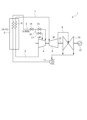
- FIG. 1 is a system schematic diagram of a steam turbine facility including a steam turbine according to some embodiments.
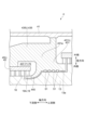
- FIG. 1 is a cross-sectional view showing a schematic structure of a steam turbine according to some embodiments of the present disclosure, in which a high-pressure turbine has an annulus.
- FIG. 3 is a cross-sectional view showing an outline of part A in FIG. 2 .
- 2 is a cross-sectional view showing an outline of the structure of a part of a high-pressure turbine in which a first annular portion, a blade ring, and an inner casing are each separate members.
- FIG. 4 is a cross-sectional view showing a schematic structure of a portion of another example high-pressure turbine.
- FIG. 4 is a cross-sectional view showing the outline of the structure of a portion of a high-pressure turbine of yet another example.
- 3 is a cross-sectional view showing a schematic structure of a portion of the high-pressure turbine shown in FIG. 2.
- FIG. 2 is a schematic enlarged view of a first stage vane and its vicinity according to some embodiments.
- FIG. 4 is a schematic enlarged view of the vicinity of a first stage vane according to some embodiments, illustrating another example of the second annular portion.
- FIG. 11 is a schematic enlarged view of the vicinity of a first stage vane according to some embodiments, illustrating yet another example of the second annular portion.
- 3 is a flowchart showing an assembly procedure for the high-pressure turbine shown in FIG.
- FIG. 4 is a flowchart showing a procedure for assembling a high-pressure turbine having an integrally formed annulus and a front stage blade ring.
- 5 is a flowchart showing an assembly procedure for the high-pressure turbine shown in FIG. 4 in which the first annular portion, the blade ring, and the inner casing are each separate members.
- expressions indicating that things are in an equal state such as “identical,””equal,” and “homogeneous,” not only indicate a state of strict equality, but also indicate a state in which there is a tolerance or a difference to the extent that the same function is obtained.
- expressions describing shapes such as a rectangular shape or a cylindrical shape do not only refer to rectangular shapes, cylindrical shapes, etc. in the strict geometric sense, but also refer to shapes that include uneven portions, chamfered portions, etc., to the extent that the same effect is obtained.
- the expressions “comprise,””include,””have,””includes,” or “have” of one element are not exclusive expressions excluding the presence of other elements.
- FIG. 1 is a schematic diagram of a steam turbine facility equipped with a steam turbine according to some embodiments.
- the steam turbine facility 1 has, as its main equipment, a boiler 2, a high-pressure turbine 4, an intermediate-pressure turbine 8, a low-pressure turbine 10, a condenser 11, and a generator 12.
- the high-pressure turbine 4, the intermediate-pressure turbine 8, and the low-pressure turbine 10 are connected by a rotor 13, and the rotor 13 is connected to the generator 12.
- the main steam generated in the boiler 2 flows down the main steam pipe 3 and is led to the inlet of the high-pressure turbine 4.
- the exhaust steam discharged by driving the high-pressure turbine 4 flows down the low-temperature reheat pipe 5 from the high-pressure turbine 4 and is led to the reheater 6 of the boiler 2 and reheated.
- the steam heated in the reheater 6 flows down the high-temperature reheat pipe 7 and is led to the intermediate-pressure turbine 8, which is driven, and then flows down the main steam pipe 9 and is led to the low-pressure turbine 10.
- the exhaust steam discharged by driving the low-pressure turbine 10 is led to the condenser 11, where it is cooled and condensed, and then reintroduced to the boiler 2 as feed water.
- the high-pressure turbine 4, the intermediate-pressure turbine 8, and the low-pressure turbine 10 are connected by the rotor 13, and the rotational power is transmitted to the generator 12 via the rotor 13, which converts the rotational power into electricity.
- the main steam pipe 3 through which the main steam flows from the boiler 2 to the high-pressure turbine 4 is provided with a main steam stop valve 14 and a main steam control valve 15 from the upstream to downstream in the steam flow direction.
- a bypass pipe 16 is provided branching off from the main steam pipe 3 between the main steam stop valve 14 and the main steam control valve 15.
- the bypass pipe 16 branching off from the main steam pipe 3 is connected to an intermediate stage of the high-pressure turbine 4, so that a portion of the main steam flowing through the main steam pipe 3 bypasses a portion of the upstream stage of the high-pressure turbine 4 and is introduced from the intermediate stage to the high-pressure turbine 4.
- An overload valve 17 is provided in the bypass pipe 16 to control the amount of bypass steam flowing through the bypass pipe 16.
- FIG. 2 is a cross-sectional view showing an outline of the structure of a steam turbine 20 according to some embodiments of the present disclosure, in which a high-pressure turbine 4 (described later) has an annular body 43 .
- the steam turbine 20 according to some embodiments is a center-high integrated steam turbine in which a high-pressure turbine 4 and an intermediate-pressure turbine 8 are integrally configured. Note that, of the high-pressure turbine 4 and the intermediate-pressure turbine 8 that are integrally configured, Fig. 2 mainly illustrates the structure of the high-pressure turbine 4.
- the high-pressure turbine 4 shown in FIG. 2 includes an outer casing 41 , an annular body 43 , and a front stage blade ring 45 .
- the outer casing 41 is divided horizontally into an upper half 41U and a lower half 41L.
- the outer casing 41 when there is no need to distinguish between the upper half 41U and the lower half 41L, they may simply be referred to as the outer casing 41.
- a plurality of turbine stages are provided in the axial direction on the inner peripheral side of the outer casing 41, and a main steam flow passage 21 through which main steam flows is formed.
- Each turbine stage is composed of a plurality of moving blades 18 fixed in the circumferential direction of the rotor 13, and stator vanes 19 fixed to an annular body 43 or a front stage blade ring 45, which will be described in detail later, so as to face the upstream side of the moving blades 18.
- the upstream side of the flow of main steam flowing through the main steam flow passage 21 will also be referred to as the axial upstream side
- the downstream side of the flow of main steam flowing through the main steam flow passage 21 will also be referred to as the axial downstream side.
- the circumferential direction of the rotor 13 will also be simply referred to as the circumferential direction
- the radial direction of the rotor 13 will also be simply referred to as the radial direction.
- the intermediate pressure turbine 8 shown in FIG. 2 has multiple turbine stages arranged in the axial direction on the inner circumferential side of the outer casing 41, and a main steam flow passage 81 through which main steam flows is formed.
- the turbine stages are composed of multiple rotor blades 83 fixed in the circumferential direction of the rotor 13, and stator blades 85 fixed to a blade ring 87 so as to face the upstream side of the rotor blades 83.
- the steam turbine 20 is provided with a plurality of nozzles.
- the plurality of nozzles include, for example, a first inlet nozzle 91 for supplying main steam Sin from the main steam pipe 3 to the high-pressure turbine 4, an outlet nozzle 94 for discharging exhaust steam Sout discharged by driving the high-pressure turbine 4 to the low-temperature reheat pipe 5, and a third inlet nozzle 95 for supplying reheated steam Sr from the high-temperature reheat pipe 7 to the intermediate-pressure turbine 8.
- annular body 43 In the high-pressure turbine 4 shown in Figure 2, the annular body 43 is a single member provided radially inward of the outer casing 41, and is formed with a first annular portion 431, a rear stage vane holding area 433, and an inner casing area 435.
- the first annular portion 431 In the high-pressure turbine 4 shown in Fig. 2, the first annular portion 431 is provided between the high-pressure turbine 4 and the intermediate-pressure turbine 8, which are provided integrally.
- the first annular portion 431 includes an area in which a seal device 51 that seals the gap between the outer circumferential surface 13a of the rotor 13 and the annular body 43 is disposed.
- the seal device 51 is, for example, a labyrinth seal having seal fins.
- the first annular portion 431 in the high-pressure turbine 4 shown in FIG. 2 is a region corresponding to a member called a dummy ring in a conventional steam turbine.
- the first annular portion 431 in the high-pressure turbine 4 shown in Figure 2 has an extension portion 440 that extends axially downstream from the area in which the sealing device 51 is arranged, along the outer circumferential surface 13a of the rotor, radially inward from a first cavity 71 described later, and toward the axially downstream side.
- the rear stage stator blade holding region 433 is a region that holds the stator blades 19 in the rear stage.
- the rear stage stator vane holding region 433 in the high pressure turbine 4 shown in Fig. 2 is a region corresponding to a member called a blade ring in a conventional steam turbine.
- the rear stage stator vane holding region 433 in the high pressure turbine 4 shown in Fig. 2 is a region corresponding to a blade ring that holds the stator vanes 19 of a stage downstream of a forward stage blade ring 45 described later in a conventional steam turbine, that is, a region corresponding to a blade ring that corresponds to a rear stage blade ring relative to the forward stage blade ring 45.
- the inner casing region 435 is a region that connects the first annular portion 431 and the rear stage stator vane holding region 433 .
- the inner casing region 435 in the high-pressure turbine 4 shown in FIG. 2 is a region corresponding to a member called an inner casing in a conventional steam turbine. That is, in the high pressure turbine 4 shown in FIG. 2, the annular body 43 corresponds to a dummy ring, a rear stage blade ring, and an inner casing in a conventional steam turbine, which are formed into a single member.
- a recess 437 is provided in the inner circumferential portion 43i of the annular body 43 between the first annular portion 431 and the rear stage vane holding region 433.
- the front stage vane ring 45 which will be described in detail below, is disposed in the recess 437.
- the recess 437 forms a first cavity 71 which will be described later.
- the first cavity 71 is connected to a first inlet nozzle 91 .
- the annular body 43 is divided in a horizontal plane into an upper annular body half 43U and a lower annular body half 43L.
- the annular body 43 when there is no need to distinguish between the upper half portion 43U of the annular body and the lower half portion 43L of the annular body, they may be simply referred to as the annular body 43.
- FIG. 3 is a cross-sectional view showing an outline of part A in FIG. 2, the front stage blade ring 45 is a member separate from the annular body 43, and is attached to the annular body 43 to hold the stator blades 19 of the front stage.
- the front stage blade ring 45 extends in the axial direction.
- the forward stage blade ring 45 holds multiple stages of stator vanes 19, including the first stage stator vane 19A, which is the stator vane 19 of the most upstream stage.
- the forward stage blade ring 45 is divided in the horizontal plane into the forward stage blade ring upper half 45U and the forward stage blade ring lower half 45L.
- the forward stage blade ring 45 when there is no need to distinguish between the forward stage blade ring upper half 45U and the forward stage blade ring lower half 45L, they may be simply referred to as the forward stage blade ring 45.
- the first cavity 71 is a cavity to which main steam Sin is supplied from the main steam pipe 3 .
- the first cavity 71 is defined by the inner circumferential portion 43i of the annular body 43, the first annular portion 431, and the front stage blade ring 45.
- the first cavity 71 is defined by the inner circumferential portion 43i of the annular body 43, the first annular portion 431, the front stage blade ring 45, and the second annular portion 200.
- the first cavity 71 is defined by the back surface 451b of the front stage blade ring 45, a region on the radially outer side and axially upstream side of the first cavity 71 on the inner circumferential surface 437i of the recess 437 of the annular body 43, and a radially outer surface 442 (described later) of the extension portion 440.
- a flow passage forming region 205 (described later) of the second annular portion 200 (described later) defines a part of the first cavity 71.
- the main steam Sin supplied to the first cavity 71 flows from the first cavity 71 toward the first stage stator vane 19A, which is the stator vane 19 of the most upstream stage, and flows into the main steam flow passage 21. That is, the first cavity 71 is a steam inlet passage 75 of the high-pressure turbine 4 .
- FIG. 4A is a cross-sectional view showing an outline of the structure of a portion of a high-pressure turbine 4A in which the first annular portion 431A, the blade ring 433A, and the inner casing 435A are each separate components.
- the first annular portion 431A is a component known as a dummy ring in conventional steam turbines.
- the first annular portion 431A corresponds to the first annular portion 431 in the high-pressure turbine 4 shown in FIG. 2 described above, and has an extension portion 440 similar to the first annular portion 431.
- the first annular portion 431A is divided in a horizontal plane into a first annular portion upper half 431AU and a first annular portion lower half (not shown) that is paired with the first annular portion upper half 431AU.
- first annular portion 431A when there is no need to distinguish between the first annular portion upper half 431AU and the first annular portion lower half, they may be simply referred to as the first annular portion 431A.
- the blade ring 433A is divided in a horizontal plane into an upper half 433AU and a lower half (not shown). In the following description, when there is no need to distinguish between the upper half 433AU and the lower half, they may be simply referred to as the blade ring 433A.
- the inner casing 435A is horizontally divided into an upper half 435AU and a lower half (not shown). In the following description, when there is no need to distinguish between the upper half 435AU and the lower half, they may be simply referred to as the inner casing 435A.
- the steam turbine 20 may include a high-pressure turbine 4A having the structure shown in FIG. 4A. That is, the first annular portion 431A, the blade ring 433A, and the inner casing 435A of the high-pressure turbine 4A may each be separate components.
- the size of the first annular portion 431A becomes relatively large. As a result, the turbine size, including the inner casing 435A and the outer casing 41A, becomes larger.
- the first annular portion 431, the rear stage vane holding area 433, and the inner casing area 435 are formed in the annular body 43, which is a single member. Therefore, since there is no fitting portion 431Aa of the first annular portion 431A in the steam turbine 4A having the structure shown in FIG. 4A as in the conventional steam turbine, the annular body 43 can be made smaller than the inner casing 435A in the steam turbine 4A having the structure shown in FIG. 4A, compared to the steam turbine 4A having the structure shown in FIG. 4A. This allows the high-pressure turbine 4 and the steam turbine 20 shown in FIG. 2 to be made smaller. In other words, the high-pressure turbine 4 shown in FIG. 2 can supply higher pressure steam while maintaining the same physical size as the outer casing of the conventional steam turbine.
- the front stage blade ring 45 may be formed integrally with the annular body 43. That is, in the high-pressure turbine 4 shown in FIG 2, the annular body 43 may have a configuration similar to that in which the blade ring 433A and the inner casing 435A are formed integrally.
- Fig. 4B is a cross-sectional view showing an outline of the structure of a part of a high-pressure turbine 4B including an inner casing 435B that corresponds to the blade ring 433A and the inner casing 435A in Fig. 4A that are integrally formed.
- the high-pressure turbine 4B shown in Fig. 4B includes a first annular portion 431B that is a separate member from the inner casing 435B.
- an inner casing 435B has a stator vane holding area 433B.
- the stator vane holding area 433B is an area corresponding to a member called a blade ring in a conventional steam turbine, and is an area that holds multiple stages of stator vanes 19.
- the inner casing 435B is divided into an inner casing upper half 435BU and an inner casing lower half (not shown) by a horizontal plane. In the following description, when there is no need to distinguish between the inner casing upper half 435BU and the inner casing lower half, they may be simply referred to as the inner casing 435B.
- the first annular portion 431B has a configuration similar to that of the first annular portion 431A in the high-pressure turbine 4A shown in Fig. 4A. That is, in the high-pressure turbine 4B shown in Fig. 4B, the first annular portion 431B has a fitting portion 431Ba that fits with the inner casing 435B.
- the first annular portion 431B is a member called a dummy ring in a conventional steam turbine.
- the first annular portion 431B corresponds to the first annular portion 431 in the high-pressure turbine 4 shown in Fig. 2 described above, and has an extension portion 440 similar to the first annular portion 431.
- the first annular portion 431B is divided into a first annular portion upper half 431BU and a first annular portion lower half (not shown) on a horizontal plane.
- first annular portion 431B when there is no need to distinguish between the first annular portion upper half 431BU and the first annular portion lower half, they may be simply referred to as the first annular portion 431B.
- Figure 4C is a cross-sectional view showing an outline of the structure of a portion of a high-pressure turbine 4C having an inner casing 435C that corresponds to the annular body 43 and the front stage blade ring 45 in the high-pressure turbine 4 shown in Figure 2 being formed integrally.
- the inner casing 435C of the high-pressure turbine 4C shown in Figure 4C corresponds to the inner casing 435B and the first annular portion 431B in the high-pressure turbine 4B shown in Figure 4B being formed integrally.
- the inner casing 435C has a first annular portion 431C similar to the first annular portion 431 in the high-pressure turbine 4 shown in Figure 2, and a stator vane holding area 433C similar to the stator vane holding area 433B in the high-pressure turbine 4B shown in Figure 4B.
- the inner casing 435C is divided into an inner casing upper half 435CU and an inner casing lower half (not shown) by a horizontal plane.
- the inner casing 435C when there is no need to distinguish between the inner casing upper half 435CU and the inner casing lower half, they may be simply referred to as the inner casing 435C.
- FIG. 4D is a cross-sectional view showing an outline of the structure of a portion of the high-pressure turbine 4 shown in FIG. 2.
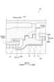
- FIG. 5A is a schematic enlarged view of the vicinity of a first stage stator vane 19A according to some embodiments.
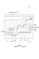
- FIG. 5B is a schematic enlarged view of the vicinity of the first stage stator vane 19A according to some embodiments, illustrating another example of the second annular portion 200 described later.
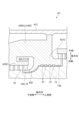
- FIG. 5C is a schematic enlarged view of the vicinity of the first stage stator vane 19A according to some embodiments, illustrating yet another example of the second annular portion 200 described below.
- the first stage stator vane 19A has an airfoil portion 191 , an outer shroud 192 positioned radially outward from the airfoil portion 191 , and an inner shroud 193 positioned radially inward from the airfoil portion 191 .
- the blade ring grooves 455 into which the outer shrouds 192 are inserted will be described.
- the forward stage blade ring 45, the blade ring 433A, the stator vane retaining area 433B, and the stator vane retaining area 433C have blade ring grooves 455 into which each of the outer shrouds 192 of the multiple first stage stator vanes 19A is inserted, and a groove portion 456 into which a portion of the caulking material 460 described later enters.
- the blade ring groove 455 is recessed radially outward from the radially inner surface facing the main steam flow passage 21 in the forward stage blade ring 45, the blade ring 433A, the stator blade holding area 433B, and the stator blade holding area 433C, and extends circumferentially.
- the groove portion 456 is recessed from an axially upstream side surface 455u of the blade ring groove 455 toward the axially upstream side, and extends in the circumferential direction.
- a region radially inward of the groove portion 456 is axially separated from each of the axially upstream side surfaces 192u of the outer shroud 192 inserted into the blade ring groove 455. Therefore, the groove portion 456, the side surface 455u, and each of the axially upstream side surfaces 192u of the outer shroud 192 inserted into the blade ring groove 455 form a storage space 457 having an L-shaped cross section perpendicular to the circumferential direction.
- a caulking member 460 is inserted into the storage space 457 as described later.
- the storage space 457 is open radially inward.
- the caulking member 460 is a member for restricting the movement of the multiple first stage stator vanes 19A relative to the forward stage blade ring 45, the blade ring 433A, the stator vane holding area 433B, and the stator vane holding area 433C.
- the caulking member 460 is a ring-shaped member extending in the circumferential direction, and is made of a metal that is softer than the first stage stator vanes 19A, such as stainless steel.
- the cross-sectional shape of the caulking member 460 perpendicular to the circumferential direction is L-shaped so that it fits into the L-shaped storage space 457.
- the caulking members 460 are inserted into the storage space 457 from the circumferential ends of the forward stage blade ring upper half 45U, the forward stage blade ring lower half 45L, the blade ring upper half 433AU, the blade ring lower half (not shown) of the blade ring 433A, the upper and lower halves of the stator vane holding area 433B, and the upper and lower halves of the stator vane holding area 433C.
- the caulking members 460 are then plastically deformed within the storage space 457 by striking the radially inner end of the caulking members 460 with a tool such as a hammer from the radially inner opening in the storage space 457.
- the multiple outer shrouds 192 are crimped to the forward stage blade ring 45, the blade ring 433A, the stator vane holding area 433B, and the stator vane holding area 433C by the caulking members 460.
- the outer shrouds 192 of the multiple first stage stator vanes 19A are constrained so as not to move radially and axially relative to the forward stage blade ring 45, the blade ring 433A, the stator vane holding area 433B, and the stator vane holding area 433C.
- Each of the inner shrouds 193 of the multiple first stage stator vanes 19A has an attachment portion 194 for attaching a second annular portion 200, which will be described later, to the inner shroud 193.
- the attachment portion 194 is, for example, an engagement groove 195 that is recessed radially outward from the radially inner surface of the inner shroud 193 and extends in the circumferential direction.
- the engagement groove 195 is formed, for example, such that the axial dimension of the engagement groove 195 is larger on the radial outer side than on the radial inner side. This makes it possible to restrict radially inward and axial movement of the second annular portion 200 relative to the inner shroud 193 in a state in which an engagement protrusion 201 of the second annular portion 200 described later is inserted into the engagement groove 195.
- the second annular portion 200 is a member that protrudes from a region radially inward from the inner shroud 193 of the first stage stator vane 19A toward the axially upstream side, extends in the circumferential direction, and has an engagement protrusion 201 and a radially second opposing portion 203.
- the second annular portion 200 has a flow passage forming region 205 that defines a part of the first cavity 71, and an axially second opposing portion 207.
- the second annular portion 200 according to some embodiments is divided into at least two parts: a lower half of the second annular portion 200 attached to the front stage blade ring lower half 45L, the lower half of the blade ring 433A, or the first stage stator vane 19A held in the lower half of the stator vane holding area 433B or the stator vane holding area 433C, and an upper half of the second annular portion 200 attached to the front stage blade ring upper half 45U, the blade ring upper half 433AU, or the first stage stator vane 19A held in the upper half of the stator vane holding area 433B or the stator vane holding area 433C.
- the lower half of the second annular portion 200 and the upper half of the second annular portion 200 are further divided into a plurality of (e.g., two)
- the engaging protrusion 201 is a protrusion that protrudes radially outward from an axially downstream region of the second annular portion 200 and extends in the circumferential direction.
- the engaging protrusion 201 is a protrusion that can engage with the engaging groove 195 of the inner shroud 193, and is formed such that, for example, the axial dimension of the engaging protrusion 201 is larger on the radially outer side than on the radially inner side. That is, the cross-sectional shape perpendicular to the circumferential direction of the engaging protrusion 201 is similar to the cross-sectional shape perpendicular to the circumferential direction of the engaging groove 195 of the inner shroud 193.
- the engaging protrusion 201 extends in the circumferential direction so as to be inserted into the engaging grooves 195 of at least two or more inner shrouds 193 aligned in the circumferential direction, and restricts the circumferentially adjacent inner shrouds 193 from moving relatively in the axial and radial directions. Therefore, the strength of the first stage stator vane 19A is improved compared to a case in which the second annular portion 200 is not attached to the inner shroud 193.
- the radial second opposed portion 203 is a portion that radially faces the radial first opposed portion 441 of the extension portion 440 of the first annular portion 431, 431A, 431B, or 431C. That is, the extension portion 440 of the first annular portion 431, 431A, 431B, or 431C has the radial first opposed portion 441 that radially faces the radial second opposed portion 203 at the axial downstream end of the extension portion 440.
- the first radial facing portion 441 and the second radial facing portion 203 of the extending portion 440 face each other with a gap therebetween in the radial direction.
- a seal device 52 for sealing a gap between the first radial facing portion 441 and the second radial facing portion 203 is provided between the first radial facing portion 441 and the second radial facing portion 203.
- the seal device 52 is, for example, a labyrinth seal having seal fins.
- the radially second opposing portion 203 is located radially inward of the radially first opposing portion 441 of the extending portion 440 .
- the second radially opposed portion 203 is located radially outward of the first radially opposed portion 441 of the extending portion 440 .
- the flow passage forming region 205 has a surface 205s that defines a portion of the first cavity 71, i.e., a portion of the steam inlet flow passage 75.
- the surface 205s is located between an axially downstream edge 442d of a radially outer surface 442 of the extension portion 440 of the first annular portion 431, 431A, 431B, 431C and an axially upstream edge 193su of a radially outer surface 193s of the inner shroud 193.
- the radially outer surface 442 of the extension portion 440 defines a portion of the first cavity 71, i.e., a portion of the steam inlet flow passage 75.
- the second radially opposed portion 203 is a part of the flow passage forming region 205 .
- the second annular portion 200 shown in Figures 5A and 5C has a second axial opposing portion 207 extending in the circumferential direction and radially inward from an axially upstream edge 205su of a surface 205s of a flow passage forming region 205.
- the first annular portions 431, 431A, 431B, and 431C shown in Figures 5A, 5B, and 5C have a first axial opposing portion 443 extending in the circumferential direction and radially inward from an axially downstream edge 442d of a radially outer surface 442 of an extension portion 440.
- the first axial facing portion 443 shown in FIG. 5B faces and is spaced apart from the axially upstream surface 193u of the inner shroud 193. Therefore, even if the first axial facing portion 443 moves axially downstream during operation of the high-pressure turbines 4, 4A, 4B, 4C and the axially upstream surface 193u of the inner shroud 193 moves axially upstream, the first axial facing portion 443 and the axially upstream surface 193u of the inner shroud 193 do not come into contact with each other.
- the axial position of the axially downstream end 443d of the first axially opposing portion 443 may be located axially upstream of the axial position of the axially upstream end 451u of the forward stage blade ring 45, the blade ring 433A, the stator vane holding area 433B, and the stator vane holding area 433C.
- the steam turbine 20 has the following features.
- Some embodiments of the high-pressure turbine 4, 4A, 4B, 4C include an inner casing region 435 corresponding to the inner casing 435A, 435B, 435C or the inner casing 435A, 435B, 435C.
- Some embodiments of the high-pressure turbine 4, 4A, 4B, 4C include a first annular portion 431, 431A, 431B, 431C coupled to the inner casing 435A, 435B, 435C or integrally formed with the inner casing region 435, defining at least a portion of the steam inlet passage 75 and carrying a sealing device 51 arranged on the outer circumferential surface 13a of the rotor 13.
- Some embodiments of the high-pressure turbine 4, 4A, 4B, 4C include a plurality of first stage vanes 19A spaced apart in the circumferential direction. Some embodiments of the high-pressure turbine 4, 4A, 4B, 4C include a blade ring 433A, a forward stage blade ring 45, or a vane holding area 433B, 433C that is coupled to the inner casing 435A or the inner casing area 435 or is integrally formed with the inner casing 435B, 435C and holds at least a plurality of first stage vanes 19A.
- Some embodiments of the high-pressure turbine 4, 4A, 4B, 4C include a second annular portion 200 that is attached to the inner shroud 193 of the first stage vanes 19A of the plurality of first stage vanes 19A. Some embodiments of the high-pressure turbine 4, 4A, 4B, 4C include a sealing device 52 provided between the first annular portion 431, 431A, 431B, 431C and the second annular portion 200.
- the strength of the first stage stator vane 19A can be improved by the second annular portion 200.
- a seal device 52 is provided between the first annular portion 431, 431A, 431B, 431C and the second annular portion 200, so that steam leakage from between the first annular portion 431, 431A, 431B, 431C and the second annular portion 200 can be reduced.
- the second annular portion 200 may have a flow passage forming region 205 that defines a portion of the steam inlet flow passage 75 axially downstream of the region defined by the first annular portions 431, 431A, 431B, 431C.
- the first annular portion 431, 431A, 431B, 431C may have a radial first opposing portion 441 that faces the second annular portion 200 in the radial direction radially inward of the blade ring 433A, the forward stage blade ring 45, or the stator vane holding region 433B, 433C.
- the second annular portion 200 may have a radial second opposing portion 203 that faces the radial first opposing portion 441 in the radial direction.
- the seal device 52 may seal a gap between the radial first opposing portion 441 and the radial second opposing portion 203.
- the first radial opposing portion 441 and the second radial opposing portion 203 overlap in the axial direction, and the sealing device 52 is disposed in this overlapping region to seal the gap between the first radial opposing portion 441 and the second radial opposing portion 203.
- This makes it possible to reduce leakage of steam from the gap between the first annular portions 431, 431A, 431B, 431C and the second annular portion 200.
- the first radially opposing portion 441 and the second radially opposing portion 203 may be located axially upstream of the inner shroud 193.
- the first radial opposing portion 441 and the second radial opposing portion 203 do not need to overlap radially with the inner shroud 193, so the diameter of the rotor 13 can be made larger than when the first radial opposing portion 441 and the second radial opposing portion 203 overlap radially with the inner shroud 193, and the strength of the rotor 13 can be ensured.
- the second annular portion 200 may have an opposing surface 209 that radially faces the outer circumferential surface 13a of the rotor 13.
- the first radial opposing portion 441 and the second radial opposing portion 203 may be located radially outward of the opposing surface 209. This allows the diameter of the rotor 13 to be larger than when the first radial opposing portion 441 and the second radial opposing portion 203 are positioned radially inward from the opposing surface 209, thereby ensuring the strength of the rotor 13.
- the radially second opposing portion 203 may be located radially inward of the radially first opposing portion 441, as shown in Figures 5A and 5B. This makes it possible to easily assemble the high-pressure turbine 4, as described below, even if the inner casing region 435 and the first annular portion 431 are formed integrally, and even if the inner casing region 435C and the first annular portion 431C are formed integrally.
- the radially second opposing portion 203 may be located radially outward of the radially first opposing portion 441, as shown in FIG. 5C. This makes it possible to easily assemble the steam turbine 4A as described below when the inner casing 435A, the first annular portion 431A, and the blade ring 433A are configured to be separable.
- the first annular portion 431, 431A, 431B, 431C may have a first axially opposed portion 443 axially opposed to the second annular portion 200.
- the second annular portion 200 may have a second axially opposed portion 207 axially opposed to the first axially opposed portion 443 and spaced apart from it in the axial direction.
- the second annular portion 200 may have an engagement protrusion 201 that protrudes radially outward and extends circumferentially.
- the inner shroud 193 may have an engagement groove 195 that is engageable with the engagement protrusion 201.
- the second annular portion 200 may be restricted from moving in the radial and axial directions relative to the inner shroud 193. This restricts relative movement between the inner shroud 193 and the second annular portion 200 in the radial and axial directions, thereby improving the strength of the first stage stator vane 19A.
- the first annular portion 431, 431C may be integrally formed with the inner casing region 435 or the inner casing 435C, as shown in Figures 2, 4C and 4D.
- the first annular portions 431, 431C can be made smaller than when the first annular portions 431A, 431B and the inner casings 435A, 435B are separate as shown in Figures 4A and 4B, and the high-pressure turbines 4, 4C can be made smaller.
- the forward stage blade ring 45 and the blade ring 433A may be separate members from the inner casing region 435 and the inner casing 435A, and may be coupled to the inner casing region 435 and the inner casing 435A, which are separate members. That is, as shown in Figures 2, 4A and 4D, in the high-pressure turbines 4, 4A, the front stage blade ring 45 and the inner casing region 435 may be separate entities, and the blade ring 433A and the inner casing 435A may be separate entities.
- the forward stage blade ring 45 may be integrally formed with the inner casing region 435 . That is, in the high-pressure turbine 4 shown in FIG. 2, the front stage blade ring 45 and the inner casing region 435 may be integrally formed like the inner casings 435B, 435C in the high-pressure turbines 4B, 4C shown in FIGS. 4B and 4C.
- the first annular portion 431A may be a separate member from the inner casing 435A and may be coupled to the inner casing 435A.
- the blade ring 433A may be a separate member from the inner casing 435A and may be coupled to the inner casing 435A. That is, as shown in FIG. 4A, in a high-pressure turbine 4A, a first annular portion 431A, an inner casing 435A, and a blade ring 433A may be separate bodies.
- FIG. 6 is a flowchart showing an assembly procedure for the high-pressure turbine 4 including the annular body 43 and the front stage blade ring 45 which is a member different from the annular body 43 shown in FIGS. 2 and 4D.
- FIG. 7 is a flowchart showing the procedure for assembling the high-pressure turbine 4C shown in FIG. 4C in which the annular body 43 and the front stage blade ring 45 are integrally formed.
- FIG. 8 is a flowchart showing an assembly procedure for the high-pressure turbine 4A in which the first annular portion 431A, the blade ring 433A, and the inner casing 435A shown in FIG. 4A are each separate members.
- the method of assembling the high-pressure turbine 4 shown in Figures 2 and 4D which has an annular body 43 and a front stage blade ring 45 that is a different member from the annular body 43, includes a first step S11, a second step S12, a third step S13, and a fourth step S14, as shown in Figure 6.
- the radial second opposing portion 203 is located radially inward of the radial first opposing portion 441.
- the axial position of the axially downstream end portion 443d of the axially first opposing portion 443 is located axially upstream of the front stage blade ring 45 and the axially upstream end portion 451u of the inner region 451 of the blade ring 433A.
- the first step S11 is a step of attaching a plurality of stator vanes 19, including a plurality of first stage stator vanes 19A, to an annular body lower half 43L molded integrally with the lower half of the first annular portion 431, and attaching a forward stage blade ring lower half 45L in which the lower half of the second annular portion 200 is attached to the inner shroud 193 of the first stage stator vanes 19A.
- the annular body lower half 43L is attached to the outer casing lower half 41L in advance prior to the implementation of the first step S11.
- the sealing device 52 is attached to the radial first opposing portion 441 of the extension portion 440 of the first annular portion 431 in the annular body lower half 43L in advance prior to the implementation of the first step S11.
- the axial position of the axially downstream end 443d of the first axial opposing portion 443 is located axially upstream of the axial position of the axially upstream end 451u of the inner region 451 of the forward stage blade ring 45. Therefore, when the forward stage blade ring lower half 45L is lowered vertically downward relative to the annular body lower half 43L in the first step S11, there is no interference between the end 443d of the first axial opposing portion 443 of the annular body lower half 43L and the end 451u of the inner region 451 of the forward stage blade ring lower half 45L.
- the second radial opposing portion 203 of the lower half of the second annular portion 200 attached to the front stage blade ring lower half 45L is positioned radially inward with respect to the first radial opposing portion 441, sandwiching the sealing device 52 therebetween.
- the second step S12 is a step of attaching the rotor 13, having a plurality of blades 18 attached thereto, to the annular body lower half 43L and the front stage blade ring lower half 45L after the first step S11 is performed.
- the third step S13 is a step of attaching a plurality of stator vanes 19, including a plurality of first stage stator vanes 19A, to the lower half 45L of the forward stage blade ring, and attaching the upper half 45U of the forward stage blade ring, in which the upper half of the second annular portion 200 is attached to the inner shroud 193 of the first stage stator vanes 19A.
- the fourth step S14 is a step of attaching the upper half portion 43U of the annular body, which is molded integrally with the upper half portion of the first annular portion 431, to the lower half portion 43L of the annular body, after the third step S13 is performed. It is assumed that, prior to carrying out the fourth step S14, the sealing device 52 is attached in advance to the first radially opposing portion 441 of the extending portion 440 of the first annular portion 431 in the annular body upper half portion 43U.
- the axial position of the axially downstream end 443d of the first axial opposing portion 443 is located axially upstream of the axial position of the axially upstream end 451u of the inner region 451 of the front stage blade ring 45. Therefore, when the upper half 43U of the annular body is lowered vertically downward relative to the lower half 43L of the annular body in the fourth step S14, there is no interference between the end 443d of the first axial opposing portion 443 of the upper half 43U of the annular body and the end 451u of the inner region 451 of the upper half 45U of the front stage blade ring.
- the second radial opposing portion 203 of the upper half of the second annular portion 200 attached to the front stage blade ring upper half 45U is positioned radially inward with the sealing device 52 sandwiched between the first radial opposing portion 441 as shown in FIG. 5A or FIG. 5B.
- the assembly procedure shown in FIG. 6 makes it easy to assemble the high-pressure turbine 4 shown in FIG. 2, which includes the annular body 43 and the front stage blade ring 45, which is a different member from the annular body 43.
- a method of assembling a high-pressure turbine 4C in which the front stage blade ring 45 and the annular body 43 are integrally formed as shown in FIG. 4C includes a first step S21 and a second step S22.
- the radial second opposing portion 203 is positioned radially inward relative to the radial first opposing portion 441, as shown in FIG. 5A or 5B.
- the first step S21 is a step of mounting the rotor 13, to which a plurality of rotor blades 18 are attached, to the annular body lower half 43L. 4C, the lower half of the inner casing 435C is integrally molded with the stator vane holding area 433C and the first annular portion 431C.
- the stator vane holding area 433C holds a plurality of stator vanes 19 including a plurality of first stage stator vanes 19A, and the lower half of the second annular portion 200 is attached to the inner shroud 193 of the first stage stator vanes 19A. It is assumed that, prior to carrying out the first step S21, the lower half of the inner casing 435C is attached to the lower half of the outer casing 41C in advance.
- the outer shroud 192 is inserted from the circumferential direction into the blade annular groove 455 of the stator vane holding region 433C, and the caulking member 460 is inserted from the circumferential direction into the storage space 457.
- the caulking member 460 is plastically deformed in the storage space 457 by striking the radially inner end of the caulking member 460 with a tool such as a hammer from a gap between the axially upstream surface 193u of the inner shroud 193 and the end 443d of the first axial opposing portion 443 of the extension portion 440 of the first annular portion 431.
- a tool such as a hammer from a gap between the axially upstream surface 193u of the inner shroud 193 and the end 443d of the first axial opposing portion 443 of the extension portion 440 of the first annular portion 431.
- the second step S22 is a step of attaching the inner casing upper half 435CU to the lower half of the inner casing 435C after the first step S21 is performed.
- the inner casing upper half 435CU is integrally molded with the stator vane holding area 433C and the first annular portion 431C.
- the stator vane holding area 433C holds a plurality of stator vanes 19 including a plurality of first stage stator vanes 19A, and the upper half of the second annular portion 200 is attached to the inner shroud 193 of the first stage stator vanes 19A.
- the outer shroud 192 is inserted from the circumferential direction into the blade annular groove 455 of the stator vane holding region 433C, and the caulking member 460 is inserted from the circumferential direction into the storage space 457.
- the caulking member 460 is plastically deformed in the storage space 457 by striking the radially inner end of the caulking member 460 with a tool such as a hammer from a gap between the axially upstream surface 193u of the inner shroud 193 and the end 443d of the first axial opposing portion 443 of the extension portion 440 of the first annular portion 431.
- a tool such as a hammer from a gap between the axially upstream surface 193u of the inner shroud 193 and the end 443d of the first axial opposing portion 443 of the extension portion 440 of the first annular portion 431.
- the upper half of the outer casing 41C is attached to the lower half of the outer casing 41C.
- a method of assembling the high-pressure turbine 4A shown in FIG. 4A in which the first annular portion 431A, the blade ring 433A, and the inner casing 435A are each separate members includes a first step S31, a second step S32, a third step S33, a fourth step S34, a fifth step S35, and a sixth step S36, as shown in FIG.
- the radially second opposing portion 203 is located radially outward of the radially first opposing portion 441, as shown in FIG. 5C.
- the first step S31 is a step of attaching the lower half of the blade ring 433A to the lower half of the inner casing 435A. Prior to carrying out the first step S31, the lower half of the inner casing 435A is attached in advance to the lower half of the outer casing 41. Prior to carrying out the first step S31, a plurality of stator vanes 19 including a plurality of first stage stator vanes 19A are attached to the lower half of the blade ring 433A, and the lower half of the second annular portion 200 is attached to the inner shroud 193 of the first stage stator vanes 19A.
- the second step S32 is a step of attaching the lower half of the first annular portion 431A to the lower half of the inner casing 435A and the lower half of the blade ring 433A after the first step S31 is performed. It is assumed that, prior to carrying out the second step S32, the sealing device 52 is attached in advance to the first radially opposed portion 441 of the extending portion 440 in the lower half of the first annular portion 431A.
- the second radial opposing portion 203 of the lower half of the second annular portion 200 is positioned radially outward from the first radial opposing portion 441, sandwiching the sealing device 52 therebetween.
- the third step S33 is a step of attaching a rotor 13 having a plurality of blades 18 attached to the lower half of the inner casing 435A, the lower half of the blade ring 433A, and the lower half of the first annular portion 431A after the second step S32 is performed.
- the fourth step S34 is a step of attaching the first annular portion upper half 431AU to the lower half of the first annular portion 431A after the third step S33 is performed. It is assumed that, prior to carrying out the fourth step S34, the sealing device 52 is attached in advance to the first radially opposing portion 441 of the extending portion 440 of the first annular portion upper half 431AU.
- the fifth step S35 is a step of attaching the blade ring upper half 433AU to the lower half of the blade ring 433A after the fourth step S34 is performed. It is to be noted that prior to the fifth step S35, a plurality of vanes 19 including a plurality of first stage vanes 19A are attached to the upper half 433AU of the blade ring, and the upper half of the second annular portion 200 is attached to the inner shroud 193 of the first stage vanes 19A.
- the second radial opposing portion 203 of the upper half of the second annular portion 200 attached to the upper half of the blade ring 433AU is positioned radially outward from the first radial opposing portion 441, sandwiching the sealing device 52, as shown in FIG. 5C.
- the sixth step S36 is a step of attaching the inner casing upper half 435AU to the lower half of the inner casing 435A after the fifth step S35 is performed.
- a rear stage stator vane holding area 433 is provided in the upper half 435AU of the inner casing, it is assumed that a plurality of stator vanes 19 are attached to the rear stage stator vane holding area 433 prior to carrying out the sixth step S36.
- a rear stage stator vane holding area 433 is not provided in the upper half 435AU of the inner casing, multiple stator vanes 19 are attached to the upper half of the blade ring corresponding to the rear stage stator vane holding area 433, and then, prior to carrying out the sixth step S36, the upper half of the blade ring corresponding to the rear stage stator vane holding area 433 is attached to the lower half of the blade ring corresponding to the rear stage stator vane holding area 433.
- the assembly procedure shown in Figure 8 makes it easy to assemble the high-pressure turbine 4A shown in Figure 4A, in which the first annular portion 431A, the blade ring 433A, and the inner casing 435A are each separate components.
- the present disclosure is not limited to the above-described embodiments, and includes modifications to the above-described embodiments and appropriate combinations of these modifications.
- the configurations of the high-pressure turbines 4, 4A, 4B, and 4C in the above-described embodiments can also be applied to the intermediate-pressure turbine 8 and the low-pressure turbine 10.
- the steam turbine (high-pressure turbine 4, 4A, 4B, 4C) according to at least one embodiment of the present disclosure includes an inner casing (an inner casing 435A, 435B, 435C or an inner casing region 435 corresponding to the inner casing 435A, 435B, 435C).
- the steam turbine (high-pressure turbine 4, 4A, 4B, 4C) according to at least one embodiment of the present disclosure includes a first annular portion 431, 431A, 431B, 431C that is coupled to the inner casing (an inner casing 435A, 435B) or is integrally formed with the inner casing (an inner casing 435C or an inner casing region 435), defines at least a portion of the steam inlet passage 75, and holds a first seal device (seal device 51) disposed on an outer circumferential surface 13a of the rotor 13.
- a steam turbine (high-pressure turbine 4, 4A, 4B, 4C) according to at least one embodiment of the present disclosure includes a plurality of first stage stator vanes 19A arranged at intervals in the circumferential direction of the rotor 13, and having an airfoil portion 191 and an inner shroud 193 located radially inward of the airfoil portion 191.
- the steam turbine (high-pressure turbine 4, 4A, 4B, 4C) includes a blade ring (blade ring 433A, forward stage blade ring 45, or vane holding region 433B, 433C) coupled to an inner casing (inner casing 435A or inner casing region 435) or formed integrally with the inner casing (inner casing 435B, 435C) and holding at least a plurality of first stage stator vanes 19A.
- the steam turbine (high-pressure turbine 4, 4A) according to at least one embodiment of the present disclosure includes a second annular portion 200 attached to the inner shroud 193 of a plurality of first stage stator vanes 19A.
- the steam turbine (high-pressure turbine 4, 4A, 4B, 4C) according to at least one embodiment of the present disclosure includes a second sealing device (sealing device 52) provided between the first annular portion 431, 431A, 431B, 431C and the second annular portion 200.
- the above configuration (1) allows the second annular portion 200 to improve the strength of the first stage stator vane 19A.
- the above configuration (1) allows the second sealing device (sealing device 52) to be provided between the first annular portions 431, 431A, 431B, 431C and the second annular portion 200, thereby reducing steam leakage between the first annular portions 431, 431A, 431B, 431C and the second annular portion 200.
- the second annular portion 200 may have a flow passage forming region 205 that defines a portion of the steam inlet flow passage 75 downstream in the axial direction of the rotor 13 from the region defined by the first annular portions 431, 431A, 431B, and 431C.
- the flow passage forming region 205 can prevent the distance from becoming too large. This can reduce the effect on the steam flow caused by the distance becoming larger than necessary.
- the first annular portion 431, 431A, 431B, 431C may have a radial first opposing portion 441 that faces the second annular portion 200 in the radial direction of the rotor 13 on the radial inner side of the rotor 13 than the blade ring (blade ring 433A, front stage blade ring 45, or stationary vane retaining area 433B, 433C).
- the second annular portion 200 may have a radial second opposing portion 203 that faces the radial first opposing portion 441 in the radial direction.
- the second seal device (seal device 52) may seal the gap between the radial first opposing portion 441 and the radial second opposing portion 203.
- the first radial opposing portion 441 and the second radial opposing portion 203 overlap in the axial direction, and the second sealing device (sealing device 52) is disposed in this overlapping region to seal the gap between the first radial opposing portion 441 and the second radial opposing portion 203.
- This makes it possible to reduce steam leakage from the gap between the first annular portions 431, 431A, 431B, 431C and the second annular portion 200.
- the first radially opposed portion 441 and the second radially opposed portion 203 may be located axially upstream of the inner shroud 193.
- the first radial opposing portion 441 and the second radial opposing portion 203 do not need to overlap radially with the inner shroud 193, so the diameter of the rotor 13 can be made larger than when the first radial opposing portion 441 and the second radial opposing portion 203 overlap radially with the inner shroud 193, and the strength of the rotor 13 can be ensured.
- the second annular portion 200 may have an opposing surface 209 that faces the outer peripheral surface 13a of the rotor 13 in the radial direction.
- the first radial opposing portion 441 and the second radial opposing portion 203 may be located radially outward of the rotor than the opposing surface 209.
- the above configuration (5) allows the diameter of the rotor 13 to be larger than when the first radial opposing portion 441 and the second radial opposing portion 203 are positioned radially inward from the opposing surface 209, ensuring the strength of the rotor 13.
- the second radial opposing portion 203 may be located radially inward of the rotor 13 relative to the first radial opposing portion 441.
- the above configuration (6) allows the steam turbine (high-pressure turbine 4, 4C) to be easily assembled even if the inner casing (inner casing area 435, inner casing 435C) and the first annular portion (first annular portion 431, 431C) are integrally formed.
- the second radial opposing portion 203 may be located radially outward of the rotor 13 than the first radial opposing portion 441.
- the second radial opposing portion 203 may be located radially outward of the rotor 13 than the first radial opposing portion 441. Also, according to the above configuration (7), the steam turbine 4A can be easily assembled when the inner casing 435A, the first annular portion 431A, and the blade ring 433A are configured to be separable.
- the first annular portion 431, 431A, 431B, 431C may have a first axial facing portion 443 that faces the second annular portion 200 in the axial direction of the rotor 13.
- the second annular portion 200 may have a second axial facing portion 207 that faces the first axial facing portion 443 at a distance in the axial direction.
- the gap between the first axial opposing portion 443 and the second axial opposing portion 207 can absorb thermal expansion of the first annular portion 431, 431A, 431B, 431C and the second annular portion 200.
- the second annular portion 200 may have a protrusion (engagement protrusion 201) that protrudes radially outward from the rotor 13 and extends circumferentially.
- the inner shroud 193 may have a recess (engagement groove 195) that can engage with the protrusion (engagement protrusion 201).
- the second annular portion 200 may restrict radial and axial movement of the rotor 13 relative to the inner shroud 193.
- the above configuration (9) restricts the relative radial and axial movement between the inner shroud 193 and the second annular portion 200, thereby improving the strength of the first stage stator vane 19A.
- the first annular portion 431, 431C may be formed integrally with the inner casing (inner casing region 435, inner casing 435C).
- the first annular portions 431, 431C can be made smaller than when the first annular portions 431A, 431B and the inner casings 435A, 435B are separate, and the steam turbine (high-pressure turbines 4, 4C) can be made smaller.
- higher pressure steam can be supplied while maintaining the same size as the outer casing 41A when the first annular portions 431A, 431B and the inner casings 435A, 435B are separate.
- the blade ring (the front stage blade ring 45 and the blade ring 433A) may be separate members from the inner casing (the inner casing region 435 and the inner casing 435A) and may be connected to the inner casing (the inner casing region 435 and the inner casing 435A).
- the blade ring forward stage blade ring 45 and blade ring 433A
- the inner casing inner casing region 435 and inner casing 435A
- the blade ring in the configuration of (10) above, may be formed integrally with the inner casing (inner casing region 435).
- the blade ring (forward stage blade ring 45) and the inner casing (inner casing region 435) may be formed integrally.
- the first annular portion 431A may be a separate member from the inner casing 435A and may be connected to the inner casing 435A.
- the blade ring 433A may be a separate member from the inner casing 435A and may be connected to the inner casing 435A.
- the first annular portion 431A, the blade ring 433A, and the inner casing 435A may be separate bodies.
- the steam turbine (high-pressure turbine 4) includes an inner casing (inner casing region 435).
- the steam turbine (high-pressure turbine 4) includes a first annular portion 431 that is integrally formed with the inner casing (inner casing region 435), defines at least a portion of the steam inlet passage 75, and holds a first sealing device (sealing device 51) that is arranged on the outer circumferential surface 13a of the rotor 13.
- the steam turbine (high-pressure turbine 4) includes a plurality of first-stage stator vanes 19A that are spaced apart from each other in the circumferential direction of the rotor 13 and have an airfoil portion 191 and an inner shroud 193 that is located radially inward of the airfoil portion 191.
- the steam turbine (high-pressure turbine 4) includes a blade ring (forward stage blade ring 45) that is separable from the inner casing (inner casing region 435) and holds at least a plurality of first-stage stator vanes 19A.
- the steam turbine (high-pressure turbine 4) includes a second annular portion 200 attached to an inner shroud 193 of a plurality of first-stage stator vanes 19A.
- the steam turbine (high-pressure turbine 4) includes a second sealing device (sealing device 52) provided between the first annular portion 431 and the second annular portion 200.
- a method for assembling a steam turbine (high-pressure turbine 4) includes a first step S11 of attaching a second lower half (forward stage blade ring lower half 45L) of a blade ring (forward stage blade ring 45) in which at least a plurality of first-stage stator vanes 19A are attached to a first lower half (annular body lower half 43L) of an inner casing (inner casing region 435) molded integrally with the first annular portion 431 and in which the second annular portion 200 is attached to the inner shroud 193.
- the method of assembling a steam turbine (high-pressure turbine 4) includes, after the first step S11, a second step S12 of attaching a rotor 13 to the first lower half (annular body lower half 43L) and the second lower half (forward stage blade ring lower half 45L).
- the method of assembling a steam turbine (high-pressure turbine 4) includes, after the second step S12, a third step S13 of attaching a second upper half (forward stage blade ring upper half 45U) of a blade ring (forward stage blade ring 45) having at least a plurality of first stage vanes 19A attached to the second lower half (forward stage blade ring lower half 45L) and having a second annular portion 200 attached to the inner shroud 193.
- the method of assembling a steam turbine (high-pressure turbine 4) includes a fourth step S14 of attaching the first upper half (upper half 43U of the annular body) of the inner casing (inner casing region 435) molded integrally with the first annular portion 431 to the first lower half (lower half 43L of the annular body) after the third step S13 is performed.
- the steam turbine (high pressure turbine 4) can be easily assembled.
- the steam turbine (high-pressure turbine 4C) comprises an inner casing (inner casing 435C).
- the steam turbine (high-pressure turbine 4C) comprises a first annular portion 431C formed integrally with the inner casing (inner casing 435C), defining at least a portion of the steam inlet passage 75, and holding a first sealing device (sealing device 51) arranged on the outer circumferential surface 13a of the rotor 13.
- the steam turbine (high-pressure turbine 4C) comprises a plurality of first-stage stator vanes 19A arranged at intervals in the circumferential direction of the rotor 13, and having an airfoil portion 191 and an inner shroud 193 located radially inward of the airfoil portion 191.
- the steam turbine (high-pressure turbine 4C) comprises a blade ring (stator vane holding area 433C) formed integrally with the inner casing (inner casing 435C) and holding at least a plurality of first-stage stator vanes 19A.
- the steam turbine (high pressure turbine 4C) includes a second annular portion 200 attached to an inner shroud 193 of a plurality of first stage stator vanes 19A.
- the steam turbine (high pressure turbine 4C) includes a second sealing device (sealing device 52) provided between the first annular portion 431C and the second annular portion 200.
- a method for assembling a steam turbine (high pressure turbine 4C) according to at least one embodiment of the present disclosure includes a first step S21 of attaching a rotor 13 to a blade ring (vane holding region 433C) to which at least a plurality of first stage stator vanes 19A are attached and to which the second annular portion 200 is attached to the inner shroud 193, and to a lower half (annular body lower half 43L) of an inner casing (inner casing 435C) molded integrally with the first annular portion 431C.
- the method of assembling a steam turbine (high pressure turbine 4C) includes a second step S22 in which at least a plurality of first stage vanes 19A are attached to the lower half (annular body lower half 43L) after the first step S21 is performed, and a blade ring (vane holding area 433C) in which the second annular portion 200 is attached to the inner shroud 193, and the upper half (inner casing upper half 435CU) of the inner casing (inner casing 435C) molded integrally with the first annular portion 431C are attached.
- the steam turbine (high pressure turbine 4C) can be easily assembled.
- the steam turbine (high-pressure turbine 4A) comprises an inner casing 435A.
- the steam turbine (high-pressure turbine 4A) is separable from the inner casing 435A, and is provided with a first annular portion 431A that defines at least a portion of the steam inlet passage 75 and holds a first seal device (seal device 51) that is arranged on the outer circumferential surface 13a of the rotor 13.
- the steam turbine (high-pressure turbine 4A) is provided with a plurality of first-stage stator vanes 19A that are arranged at intervals in the circumferential direction of the rotor 13 and have an airfoil portion 191 and an inner shroud 193 that is located radially inward of the airfoil portion 191.
- the steam turbine (high-pressure turbine 4A) is separable from the inner casing 435A and the first annular portion 431A, and is provided with a blade ring 433A that holds at least a plurality of first-stage stator vanes 19A.
- the steam turbine (high-pressure turbine 4A) includes a second annular portion 200 attached to an inner shroud 193 of a plurality of first-stage stator vanes 19A.
- the steam turbine (high-pressure turbine 4A) includes a second sealing device (sealing device 52) provided between the first annular portion 431A and the second annular portion 200.
- a method for assembling a steam turbine (high-pressure turbine 4A) according to at least one embodiment of the present disclosure includes a first step S31 of attaching a second lower half (lower half of the blade ring 433A) of a blade ring 433A in which at least a plurality of first-stage stator vanes 19A are attached to a first lower half (lower half of the inner casing 435A) of an inner casing 435A and in which the second annular portion 200 is attached to the inner shroud 193.
- a method of assembling a steam turbine (high-pressure turbine 4A) includes a second step S32 of attaching a third lower half (lower half of the first annular portion 431A) of the first annular portion 431A to the first lower half (lower half of the inner casing 435A) and the second lower half (lower half of the blade ring 433A) after performing the first step S31.
- a method of assembling a steam turbine (high-pressure turbine 4A) includes a third step S33 of attaching the rotor 13 to the first lower half (lower half of the inner casing 435A), the second lower half (lower half of the blade ring 433A), and the third lower half (lower half of the first annular portion 431A) after performing the second step S32.
- the method of assembling a steam turbine (high-pressure turbine 4A) includes a fourth step S34 of attaching a third upper half (first annular portion upper half 431AU) of the first annular portion 431A to the third lower half (lower half of the first annular portion 431A) after performing the third step S33.
- the method of assembling a steam turbine (high-pressure turbine 4A) includes a fifth step S35 of attaching a second upper half (blade ring upper half 433AU) of the blade ring 433A having at least a plurality of first stage vanes 19A attached to a second lower half (lower half of the blade ring 433A) and having the second annular portion 200 attached to the inner shroud 193 after performing the fourth step S34.
- the method of assembling a steam turbine (high-pressure turbine 4A) includes a sixth step S36 of attaching the first upper half (inner casing upper half 435AU) of the inner casing 435A to the first lower half (lower half of the inner casing 435A) after the fifth step S35 is performed.
- the above method (16) allows the steam turbine (high-pressure turbine 4A) to be easily assembled.
Landscapes
- Engineering & Computer Science (AREA)
- Mechanical Engineering (AREA)
- General Engineering & Computer Science (AREA)
- Chemical & Material Sciences (AREA)
- Combustion & Propulsion (AREA)
- Turbine Rotor Nozzle Sealing (AREA)
Priority Applications (4)
| Application Number | Priority Date | Filing Date | Title |
|---|---|---|---|
| DE112024002394.0T DE112024002394T5 (de) | 2023-08-02 | 2024-07-10 | Dampfturbine und Verfahren zum Montieren einer Dampfturbine |
| JP2025537802A JPWO2025028196A1 (https=) | 2023-08-02 | 2024-07-10 | |
| KR1020257041316A KR20260004547A (ko) | 2023-08-02 | 2024-07-10 | 증기 터빈 및 증기 터빈의 조립 방법 |
| CN202480039254.6A CN121358932A (zh) | 2023-08-02 | 2024-07-10 | 蒸汽涡轮及蒸汽涡轮的组装方法 |
Applications Claiming Priority (2)
| Application Number | Priority Date | Filing Date | Title |
|---|---|---|---|
| JP2023126005 | 2023-08-02 | ||
| JP2023-126005 | 2023-08-02 |
Publications (1)
| Publication Number | Publication Date |
|---|---|
| WO2025028196A1 true WO2025028196A1 (ja) | 2025-02-06 |
Family
ID=94395165
Family Applications (1)
| Application Number | Title | Priority Date | Filing Date |
|---|---|---|---|
| PCT/JP2024/024926 Pending WO2025028196A1 (ja) | 2023-08-02 | 2024-07-10 | 蒸気タービン及び蒸気タービンの組み立て方法 |
Country Status (5)
| Country | Link |
|---|---|
| JP (1) | JPWO2025028196A1 (https=) |
| KR (1) | KR20260004547A (https=) |
| CN (1) | CN121358932A (https=) |
| DE (1) | DE112024002394T5 (https=) |
| WO (1) | WO2025028196A1 (https=) |
Citations (5)
| Publication number | Priority date | Publication date | Assignee | Title |
|---|---|---|---|---|
| JPH03249303A (ja) * | 1990-02-28 | 1991-11-07 | Fuji Electric Co Ltd | 複流形蒸気タービン |
| JP2012112380A (ja) * | 2010-11-19 | 2012-06-14 | General Electric Co <Ge> | 蒸気タービン用の自己整列フロースプリッター |
| JP2017172453A (ja) * | 2016-03-23 | 2017-09-28 | 株式会社東芝 | 蒸気タービン |
| WO2022270387A1 (ja) * | 2021-06-24 | 2022-12-29 | 三菱パワー株式会社 | 初段静翼セグメント、静止ユニット、初段静翼セグメントユニット、及び蒸気タービン |
| WO2023112669A1 (ja) * | 2021-12-15 | 2023-06-22 | 三菱重工業株式会社 | 蒸気タービン |
Family Cites Families (2)
| Publication number | Priority date | Publication date | Assignee | Title |
|---|---|---|---|---|
| JP7011952B2 (ja) | 2018-03-01 | 2022-01-27 | 三菱パワー株式会社 | 静翼セグメント、及びこれを備えている蒸気タービン |
| JP7726096B2 (ja) | 2022-02-28 | 2025-08-20 | 王子ホールディングス株式会社 | 吸収性物品 |
-
2024
- 2024-07-10 JP JP2025537802A patent/JPWO2025028196A1/ja active Pending
- 2024-07-10 KR KR1020257041316A patent/KR20260004547A/ko active Pending
- 2024-07-10 WO PCT/JP2024/024926 patent/WO2025028196A1/ja active Pending
- 2024-07-10 DE DE112024002394.0T patent/DE112024002394T5/de active Pending
- 2024-07-10 CN CN202480039254.6A patent/CN121358932A/zh active Pending
Patent Citations (5)
| Publication number | Priority date | Publication date | Assignee | Title |
|---|---|---|---|---|
| JPH03249303A (ja) * | 1990-02-28 | 1991-11-07 | Fuji Electric Co Ltd | 複流形蒸気タービン |
| JP2012112380A (ja) * | 2010-11-19 | 2012-06-14 | General Electric Co <Ge> | 蒸気タービン用の自己整列フロースプリッター |
| JP2017172453A (ja) * | 2016-03-23 | 2017-09-28 | 株式会社東芝 | 蒸気タービン |
| WO2022270387A1 (ja) * | 2021-06-24 | 2022-12-29 | 三菱パワー株式会社 | 初段静翼セグメント、静止ユニット、初段静翼セグメントユニット、及び蒸気タービン |
| WO2023112669A1 (ja) * | 2021-12-15 | 2023-06-22 | 三菱重工業株式会社 | 蒸気タービン |
Also Published As
| Publication number | Publication date |
|---|---|
| KR20260004547A (ko) | 2026-01-08 |
| JPWO2025028196A1 (https=) | 2025-02-06 |
| DE112024002394T5 (de) | 2026-03-19 |
| CN121358932A (zh) | 2026-01-16 |
Similar Documents
| Publication | Publication Date | Title |
|---|---|---|
| EP2835503B1 (en) | Integrated strut and vane arrangements | |
| CA2601934C (en) | Gas turbine combustor exit duct and hp vane interface | |
| US20090191053A1 (en) | Diaphragm and blades for turbomachinery | |
| JP6574208B2 (ja) | シュラウドハンガアセンブリ | |
| JP5610802B2 (ja) | タービン中間段シールリングに関する方法および装置 | |
| US9988934B2 (en) | Gas turbine engines including channel-cooled hooks for retaining a part relative to an engine casing structure | |
| EP2660427B1 (en) | Turbine system comprising a transition duct with a convolution seal | |
| CA2660179A1 (en) | A system and method for supporting stator components | |
| CN204532440U (zh) | 喷嘴组件、及旋转机器 | |
| US10927678B2 (en) | Turbine vane having improved flexibility | |
| KR102323262B1 (ko) | 증기 터빈 및 증기 터빈 조립 방법 | |
| EP3047130B1 (en) | A gas turbine seal assembly comprising splined honeycomb seals | |
| US8596970B2 (en) | Assembly for a turbomachine | |
| WO2025028196A1 (ja) | 蒸気タービン及び蒸気タービンの組み立て方法 | |
| KR102256876B1 (ko) | 축방향 지향 밀봉 시스템 | |
| EP4007843A1 (en) | Seal assembly | |
| EP3421727B1 (en) | Gas turbine comprising a turbine vane carrier | |
| CN207420726U (zh) | 减少螺栓接头应力的隔板组件 | |
| CA2898394A1 (en) | Inner casing with impulse and reaction stages for a steam turbine engine | |
| CN107227978B (zh) | 过渡导管组件 | |
| CN120968779A (zh) | 一种具有主流燃气排出功能的涡轮机匣结构 | |
| CN113090333A (zh) | 改善的贴片环及其使用方法 |
Legal Events
| Date | Code | Title | Description |
|---|---|---|---|
| 121 | Ep: the epo has been informed by wipo that ep was designated in this application |
Ref document number: 24848855 Country of ref document: EP Kind code of ref document: A1 |
|
| ENP | Entry into the national phase |
Ref document number: 1020257041316 Country of ref document: KR Free format text: ST27 STATUS EVENT CODE: A-0-1-A10-A15-NAP-PA0105 (AS PROVIDED BY THE NATIONAL OFFICE) |
|
| WWE | Wipo information: entry into national phase |
Ref document number: 1020257041316 Country of ref document: KR |
|
| WWE | Wipo information: entry into national phase |
Ref document number: 202517126083 Country of ref document: IN |
|
| ENP | Entry into the national phase |
Ref document number: 2025537802 Country of ref document: JP Kind code of ref document: A |
|
| WWE | Wipo information: entry into national phase |
Ref document number: 2025537802 Country of ref document: JP |
|
| WWP | Wipo information: published in national office |
Ref document number: 1020257041316 Country of ref document: KR |
|
| WWP | Wipo information: published in national office |
Ref document number: 202517126083 Country of ref document: IN |
|
| WWE | Wipo information: entry into national phase |
Ref document number: 112024002394 Country of ref document: DE |
|
| WWP | Wipo information: published in national office |
Ref document number: 112024002394 Country of ref document: DE |