WO2025027803A1 - 入力装置およびシステム - Google Patents
入力装置およびシステム Download PDFInfo
- Publication number
- WO2025027803A1 WO2025027803A1 PCT/JP2023/028165 JP2023028165W WO2025027803A1 WO 2025027803 A1 WO2025027803 A1 WO 2025027803A1 JP 2023028165 W JP2023028165 W JP 2023028165W WO 2025027803 A1 WO2025027803 A1 WO 2025027803A1
- Authority
- WO
- WIPO (PCT)
- Prior art keywords
- input device
- button
- top surface
- shaft
- mouse
- Prior art date
- Legal status (The legal status is an assumption and is not a legal conclusion. Google has not performed a legal analysis and makes no representation as to the accuracy of the status listed.)
- Pending
Links
Images


Classifications
-
- A—HUMAN NECESSITIES
- A63—SPORTS; GAMES; AMUSEMENTS
- A63F—CARD, BOARD, OR ROULETTE GAMES; INDOOR GAMES USING SMALL MOVING PLAYING BODIES; VIDEO GAMES; GAMES NOT OTHERWISE PROVIDED FOR
- A63F13/00—Video games, i.e. games using an electronically generated display having two or more dimensions
- A63F13/20—Input arrangements for video game devices
- A63F13/21—Input arrangements for video game devices characterised by their sensors, purposes or types
- A63F13/213—Input arrangements for video game devices characterised by their sensors, purposes or types comprising photodetecting means, e.g. cameras, photodiodes or infrared cells
-
- A—HUMAN NECESSITIES
- A63—SPORTS; GAMES; AMUSEMENTS
- A63F—CARD, BOARD, OR ROULETTE GAMES; INDOOR GAMES USING SMALL MOVING PLAYING BODIES; VIDEO GAMES; GAMES NOT OTHERWISE PROVIDED FOR
- A63F13/00—Video games, i.e. games using an electronically generated display having two or more dimensions
- A63F13/20—Input arrangements for video game devices
- A63F13/24—Constructional details thereof, e.g. game controllers with detachable joystick handles
-
- A—HUMAN NECESSITIES
- A63—SPORTS; GAMES; AMUSEMENTS
- A63F—CARD, BOARD, OR ROULETTE GAMES; INDOOR GAMES USING SMALL MOVING PLAYING BODIES; VIDEO GAMES; GAMES NOT OTHERWISE PROVIDED FOR
- A63F13/00—Video games, i.e. games using an electronically generated display having two or more dimensions
- A63F13/90—Constructional details or arrangements of video game devices not provided for in groups A63F13/20 or A63F13/25, e.g. housing, wiring, connections or cabinets
- A63F13/92—Video game devices specially adapted to be hand-held while playing
-
- G—PHYSICS
- G06—COMPUTING OR CALCULATING; COUNTING
- G06F—ELECTRIC DIGITAL DATA PROCESSING
- G06F3/00—Input arrangements for transferring data to be processed into a form capable of being handled by the computer; Output arrangements for transferring data from processing unit to output unit, e.g. interface arrangements
- G06F3/01—Input arrangements or combined input and output arrangements for interaction between user and computer
- G06F3/03—Arrangements for converting the position or the displacement of a member into a coded form
- G06F3/0304—Detection arrangements using opto-electronic means
- G06F3/0317—Detection arrangements using opto-electronic means in co-operation with a patterned surface, e.g. absolute position or relative movement detection for an optical mouse or pen positioned with respect to a coded surface
-
- G—PHYSICS
- G06—COMPUTING OR CALCULATING; COUNTING
- G06F—ELECTRIC DIGITAL DATA PROCESSING
- G06F3/00—Input arrangements for transferring data to be processed into a form capable of being handled by the computer; Output arrangements for transferring data from processing unit to output unit, e.g. interface arrangements
- G06F3/01—Input arrangements or combined input and output arrangements for interaction between user and computer
- G06F3/03—Arrangements for converting the position or the displacement of a member into a coded form
- G06F3/033—Pointing devices displaced or positioned by the user, e.g. mice, trackballs, pens or joysticks; Accessories therefor
- G06F3/0354—Pointing devices displaced or positioned by the user, e.g. mice, trackballs, pens or joysticks; Accessories therefor with detection of two-dimensional [2D] relative movements between the device, or an operating part thereof, and a plane or surface, e.g. 2D mice, trackballs, pens or pucks
- G06F3/03543—Mice or pucks
Definitions
- This disclosure relates to input devices and systems.
- Patent Document 1 discloses a wireless mouse. This wireless mouse is intended to be used only as a mouse.
- the objective of this disclosure is to provide a new input device that can be used as a mouse and for purposes other than a mouse.
- the input device comprises a front surface, a top surface, a first side surface, a second side surface, a directional input unit, a first top surface button, and a mouse operation sensor.
- the first side surface is on one side in the left-right direction.
- the second side surface is on the other side in the left-right direction.
- the directional input unit is provided on the front surface.
- the first top surface button is provided on the top surface and can be pressed around a first rotation axis that extends in a direction that includes a left-right component.
- the mouse operation sensor detects reflected light from the detection surface that changes when one of the first and second sides is placed on the detection surface and moves over the detection surface.
- the first rotation axis may extend in a direction inclined downward from a direction perpendicular to the detected surface when one side is placed on the detected surface.
- the angle between the detection surface and the first rotation axis may be greater than 45°.
- the angle between the detection surface and the first rotation axis may be 45°.
- the first rotation axis may be along a plane parallel to the front surface.
- the input device may further include a front button provided on the front surface and depressible in a linear direction.
- the first rotation axis may be along a plane perpendicular to the linear direction.
- the input device described above may further include a second top button provided on the top surface in front of the first top button.
- the input device may further include a second top button that is provided on the top surface in front of the first top button and can be pressed in a linear direction.
- the input device described above may further include a second top button that is provided on the top surface in front of the first top button and is rotatable about a second rotation axis that extends in a direction that includes a front-to-rear component.
- the input device may further include a second top button that is provided on the top surface in front of the first top button, can be pressed in a linear direction, and can rotate around a second rotation axis that extends in a direction that includes a front-to-rear component.
- the second rotation axis may extend in a direction parallel to the detection surface when one side is placed on the detection surface.
- the first rotation axis may extend in a direction parallel to the plane direction in which the second top button can move.
- the upper end of the first top button may be located lower than the upper end of the second top button in the up-down direction. There may be a step between the first top button and the second top button.
- the input device may further include a switch that is activated when the second top button is pressed.
- the support surface of the switch may be configured so that when one side of the switch is placed on the detection surface, it is inclined downward from the direction perpendicular to the detection surface.
- the input device may further include a first biasing member and a second biasing member that bias the second top button upward.
- the switch may be disposed between the first biasing member and the second biasing member in the left-right direction.
- the angle between the detection surface and the support surface may be greater than 45°.
- the angle between the detection surface and the support surface may be 60° or more.
- the second top button may have either a first shaft hole and a first shaft arranged in the first shaft hole, and either a second shaft hole and a second shaft arranged in the second shaft hole.
- the input device may have either the other of the first shaft hole and the first shaft, and either the other of the second shaft hole and the second shaft.
- the second shaft hole may be provided on the opposite side of one side in the left-right direction from the first shaft hole, and may be longer in the left-right direction than the first shaft hole.
- the first axis may be movable in the vertical direction within the first axis hole
- the second axis may be movable in the vertical direction within the second axis hole
- the length from one side surface to the rear end of the rear surface opposite the front surface may be longer in the front-rear direction than the length from one side surface to the front end of the front surface.
- the rear end of the first top surface button may be located rearward of the rear end of one of the side surfaces in the front-to-rear direction.
- the vertical length of one side and the horizontal length of the front face may be longer than the front-to-rear length of one side.
- the input device described above may further include a hole on one side that guides reflected light to a mouse operation sensor, and a set of four buttons on the front. In the vertical direction, the hole may be located between the stick, which is the directional input unit, and the set of four buttons.
- At least a portion of one side surface may form an attachment portion for attachment to another device.
- the hole may be provided in the attachment portion.
- the input device described above may be fixed directly or indirectly to another input device.
- the other input device may be equipped with a sensor for operating a mouse.
- the bottom end of the first top button may be located between the top and bottom ends of the set of four buttons in the up-down direction.
- the set of four buttons may include a first button and a second button spaced apart from each other in the up-down direction, and a third button and a fourth button spaced apart from each other in the left-right direction and positioned between the first button and the second button in the up-down direction.
- the bottom end of the first top button may be located between the top and bottom ends of the third button and the fourth button.
- the lower end of the first top button may be located between the upper and lower ends of the stick in the up-down direction.
- the input device may further include an ejection lever that is attachable to the main body device, is provided on the rear surface opposite the front surface, and is movable from one side surface to the other side surface of the first side surface and the second side surface.
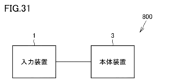
- the system disclosed herein includes the input device described above and a main unit that communicates with the input device.
- This disclosure provides a novel input device that can be used as a mouse and for purposes other than a mouse.
- FIG. 1 is a schematic perspective view showing a configuration of an input device according to a first embodiment.
- 1 is a six-sided schematic diagram illustrating a configuration of an input device according to a first embodiment.
- FIG. FIG. 2B is an enlarged view of region IIB in FIG. 2A.
- 3 is a schematic cross-sectional view showing only a protrusion along line III-III in FIG. 1.
- 1 is a schematic front view showing a configuration of an input device according to a first embodiment.
- FIG. FIG. 5 is an enlarged schematic view of region V in FIG. 4 .
- 11A and 11B are schematic diagrams showing six sides of a configuration of a second input device.
- 1 is a schematic front view illustrating a configuration of an example of an information processing device.
- FIG. 2 is a schematic front view showing an example of a configuration of a main body device.
- 2 is a schematic perspective view showing the configuration of the right side of the main unit.
- FIG. 2 is a schematic cross-sectional view showing a state in which a first input device is attached to a main body device.
- FIG. 13 is a schematic diagram showing a state before an ejection operation lever is operated.
- FIG. 13 is a schematic diagram showing a state when an ejection operation lever is operated.
- 13 is a schematic perspective view showing the configuration of a first top surface button (right).
- FIG. FIG. 2 is a schematic perspective view showing a part of an internal structure of the first input device.
- FIG. 15 is a schematic perspective view showing a state in which a first top surface button (right) is attached to the configuration shown in FIG. 14 .
- FIG. 2 is a first schematic cross-sectional view showing a part of an internal structure of the first input device.
- 11 is a schematic cross-sectional view showing the positional relationship between the first top surface button (right) and the first switch before a user operates the first top surface button (right).
- FIG. 13 is a schematic cross-sectional view showing the positional relationship between the first top surface button (right) and the first switch after a user operates the first top surface button (right).
- FIG. 11A and 11B are schematic right side and rear views showing the pressing direction of the first top button (right).
- 13 is a schematic perspective view showing the configuration of a second top surface button (right).
- FIG. 4 is a second schematic cross-sectional view showing a part of the internal structure of the first input device
- FIG. 11 is a third schematic cross-sectional view showing a part of the internal structure of the first input device
- FIG. 13 is a schematic cross-sectional view showing a state in which the second top surface button (right) has rotated around the first axis.
- FIG. 13 is a schematic cross-sectional view showing the configuration around the second top button (right) with the first top button (right) removed.
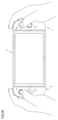
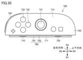
- FIG. FIG. 2 is a schematic perspective view showing a state in which the input device is held vertically.
- FIG. 2 is a front schematic view showing a state in which the input device is used as a mouse.
- FIG. 2 is a schematic side view showing a state in which the input device is used as a mouse.
- FIG. 2 is a schematic diagram showing a first state in which the device is used with both hands.
- FIG. 13 is a schematic diagram showing a second state in which the device is used with both hands.
- FIG. 2 is a schematic perspective view showing a state in which the input device is held horizontally.
- 2 is a schematic front view showing a state in which the first input device and the second input device are attached to the main body device;
- FIG. FIG. 1 is a block diagram showing a configuration of a system according to the present disclosure.
- FIG. 13 is a schematic front view showing the configurations of a first input device and a second input device according to a second embodiment.
- FIG. 11 is a schematic left side view showing the configuration of a first input device according to a second embodiment.
- FIG. 11 is a schematic front view showing a state in which the first input device according to the second embodiment is operated as a mouse.
- FIG. 13 is a schematic front view showing the configuration of an input device according to a third embodiment.
- FIG. 13 is a schematic left side view showing the configuration of an input device according to a third embodiment.
- FIG. 2 is a schematic right side view showing the configuration of the main body device. 2 is a schematic side view showing a state in which the first input device is attached to the main body device.
- FIG. 11 is a schematic left side view showing the configuration of a first input device according to a second embodiment.
- FIG. 11 is a schematic front view showing a state in which the first input device according to the second embodiment is operated as a mouse.
- FIG. 13 is a schematic front view showing the configuration of an input device according to a third embodiment.
- FIG. 13 is a schematic left side view
- FIG. 1 is a schematic perspective view showing the configuration of an input device according to the first embodiment.
- the input device 1 according to this embodiment is, for example, a game controller.
- a user can hold the input device 1 vertically (see FIG. 24, for example).
- a user can hold the input device 1 in a lifted-up state and operate various input sections of the input device 1.
- a user can use the input device 1 as a mouse (see FIG. 25, for example).
- a user can hold the input device 1 while it is placed on a desk or the like and operate various input sections of the input device 1.
- the input device 1 is a six-sided schematic diagram showing the configuration of the input device 1 according to the first embodiment.
- the input device 1 according to this embodiment has a first top button (right) 140, a second top button (right) 130, a first side button (right) 110, a second side button (right) 120, a synchronization button 50, a joystick 31 which is an example of a directional input section, a set of four buttons 32, a + button 33(1), and a home button 33(2).
- the input device 1 may have at least one or more of these input sections.
- the input device 1 may have other input sections such as a touchpad or a pressure sensor instead of or in addition to these input sections.
- the input device 1 has a front surface 15, a rear surface 16, a first side surface 11, a top surface 12, a second side surface 13, and a bottom surface 14.
- the front surface 15 is the surface that faces a user who uses the input device 1 in the integrated grip state, horizontal holding state, and vertical holding state described below.
- the front surface 15 is also referred to as the front side.
- the rear surface 16 is on the opposite side to the front surface 15.
- the rear surface 16 is also referred to as the rear side.
- the front surface 15 and the rear surface 16 are connected to the first side surface 11, the top surface 12, the second side surface 13, and the bottom surface 14, respectively.
- the direction toward the first side surface 11 is also referred to as the first direction R1.
- the first direction R1 is also referred to as the left side or leftward direction.
- the opposite direction to the first direction R1 is also referred to as the third direction R3.
- the third direction R3 is also referred to as the right side or rightward direction.
- the first direction R1 and the third direction R3 are collectively referred to as the left-right direction.
- the direction toward the upper surface 12 is also referred to as the second direction R2.
- the second direction R2 is also referred to as the upper side, upward, or upper side.
- the opposite direction to the second direction R2 is also referred to as the fourth direction R4.
- the fourth direction R4 is also referred to as the lower side, downward, or lower side.
- the second direction R2 and the fourth direction R4 are collectively referred to as the up-down direction.
- the direction toward the front surface 15 is also referred to as the fifth direction R5.
- the fifth direction R5 is also referred to as the front, front side, or front side.
- the opposite direction to the fifth direction is also referred to as the sixth direction R6.
- the sixth direction R6 is also referred to as the rear, rear side, or back side.
- the fifth direction R5 and the sixth direction R6 are collectively referred to as the front-to-rear direction.
- the first side 11 is on one side in the left-right direction.
- the first side 11 is, for example, on the left side of the front face 15.
- the first side 11 is a side that extends in the longitudinal direction of the front face 15.
- the longitudinal direction of the front face 15 is the up-down direction of the front face 15.
- the first side 11 extends in the up-down direction.
- the first side 11 may be, for example, on the right side of the front face 15.
- the second side 13 is on the other side in the left-right direction.
- the second side 13 is located opposite the first side 11.
- the second side 13 is, for example, on the right side of the front surface 15.
- the second side 13 is on the third direction R3 side of the first side surface 11.
- the second side 13 extends in the up-down direction. In another embodiment, the second side 13 may be, for example, on the left side of the front surface 15.
- the top surface 12 is connected to the upper end of the first side surface 11 and extends in a direction away from the first side surface 11.
- the top surface 12 is positioned on the upper side when held together and vertically.
- the end of the top surface 12 that is farthest from the first side surface 11 is connected to the upper end of the second side surface 13.
- the lower surface 14 is connected to the lower end of the first side surface 11 and is a side surface that extends in a direction away from the first side surface 11.
- the lower surface 14 is positioned on the lower side when held together and in a vertically held state.
- the end of the lower surface 14 that is farthest from the first side surface 11 is connected to the lower end of the second side surface 13.
- the upper surface 12 is on the second direction R2 side of the lower surface 14.
- the direction input unit 31 is provided on the front surface 15.
- the direction input unit 31 is, for example, a joystick.
- the four buttons 32 are a set of four buttons.
- the four buttons 32, the + button 33(1), and the home button 33(2) are front buttons that can be pressed in a straight line.
- the four buttons 32 include a first button 32(1), a second button 32(2), a third button 32(3), and a fourth button 32(4).
- the first button 32(1) and the second button 32(2) are spaced apart from each other in the up-down direction.
- the third button 32(3) and the fourth button 32(4) are spaced apart from each other in the left-right direction and are located between the first button 32(1) and the second button 32(2) in the up-down direction.
- the first button 32(1) is located above the second button 32(2).
- the fourth button 32(4) is located to the left of the third button 32(3).
- the joystick 31 is located between the third button 32(3) and the fourth button 32(4). In the up-down direction, the joystick 31 is located almost on an extension of the straight line connecting the first button 32(1) and the second button 32(2).
- the joystick 31 can be tilted in any direction 360 degrees, including the first direction R1 to the fourth direction R4.
- the joystick 31 can be tilted in only some directions.
- the joystick 31 can be pushed in. Instead of tilting, the joystick 31 can be slid in each direction.
- the main unit 3 can perform processing in accordance with a signal indicating the direction of operation in a program executed in response to a user's operation on the joystick 31.
- the first top button (right) 140 is provided on the top surface 12.
- the first top button (right) 140 may be disposed in a hole formed in the top surface 12, or may be disposed on the top surface 12.
- the first top button (right) 140 extends in a direction away from the first side surface 11. At least a portion of the first top button (right) 140 may be provided on the top surface 12, and other portions may be provided on a surface other than the top surface 12.
- the first top button (right) 140 has an operation surface that is curved so as to be convex outward when viewed in the direction from the front surface 15 to the rear surface 16. In addition, the rear portion of the operation surface of the first top button (right) 140 is warped up when viewed in the direction from the second side surface 13 to the first side surface 11.
- the lower end of the first top button (right) 140 may be provided between the upper and lower ends of the set of four buttons. In the vertical direction, the lower end of the first top button (right) 140 may be provided between the upper and lower ends of the third button 32(3) and the fourth button 32(4). In the vertical direction, the lower end of the first top button (right) 140 may be provided below the first button 32(1) or above the second button 32(2).
- the second top button (right) 130 is provided on the top surface 12.
- the second top button (right) 130 may be disposed in a hole formed in the top surface 12, or may be disposed on the top surface 12.
- the second top button (right) 130 is provided in front of the first top button (right) 140.
- the second top button (right) 130 is located closer to the fifth direction R5 than the first top button (right) 140.
- the second top button (right) 130 extends in a direction away from the first side surface 11. At least a portion of the second top button (right) 130 may be provided on the top surface 12, and other portions may be provided on a surface other than the top surface 12.
- the second top button (right) 130 has an operation surface that is curved so as to be convex outward when viewed in the direction from the front surface 15 to the rear surface 16.
- the lower end of the second top button (right) 130 may be provided between the upper and lower ends of the set of four buttons. In the vertical direction, the lower end of the second top button (right) 130 may be provided between the upper and lower ends of the third button 32(3) and the fourth button 32(4). In the vertical direction, the lower end of the second top button (right) 130 may be provided below the first button 32(1) or above the second button 32(2).
- the upper end of the first top surface button (right) 140 is located lower than the upper end of the second top surface button (right) 130 in the up-down direction.
- a step 5 is formed between the first top surface button (right) 140 and the second top surface button (right) 130.
- the operation surface of the second top surface button (right) 130 may be provided so as to be continuously connected to the operation surface of the first top surface button (right) 140 without a step.
- Another component may be sandwiched between the first top surface button (right) 140 and the second top surface button (right) 130.
- the input device 1 has a convex portion 100.
- the convex portion 100 has a top surface 106 and an outer peripheral surface 107 extending to the right from the top surface 106.
- the top surface 106 has a first top surface area 101, a second top surface area 102, a third top surface area 103, a fourth top surface area 104, and a fifth top surface area 105.
- the first top surface area 101 is located between the third top surface area 103 and the fourth top surface area 104.
- the second top surface area 102 is located between the fourth top surface area 104 and the fifth top surface area 105.
- the fourth top surface area 104 is located between the first top surface area 101 and the second top surface area 102.
- the first top surface area 101 is located closer to the third direction R3 than the third top surface area 103 and the fourth top surface area 104.
- the second top surface region 102 is located closer to the third direction R3 than the fifth top surface region 105 and the fourth top surface region 104.
- the outer peripheral surface 107 is connected to the top surface 106 so as to surround the outer edge of the top surface 106.
- the convex portion 100 extends in the up-down direction.
- the length of the top surface 106 in the up-down direction is longer than the length of the top surface 106 in the front-rear direction.
- the vertical length of the first side 11 is longer than the front-to-rear length of the first side 11.
- the vertical length of the first side 11 is longer than the front-to-rear length of the second side 13.
- the vertical length of the second side 13 is longer than the front-to-rear length of the second side 13.
- the vertical length of the second side 13 is longer than the front-to-rear length of the first side 11.
- the vertical length of the front surface 15 is longer than its left-right length.
- the vertical length of the front surface 15 is longer than its front-to-back length of the first side surface 11.
- the vertical length of the front surface 15 is longer than its front-to-back length of the second side surface 13.
- the vertical length of the rear surface 16 is longer than its left-to-right length.
- the vertical length of the rear surface 16 is longer than its front-to-back length of the first side surface 11.
- the vertical length of the rear surface 16 is longer than its front-to-back length of the second side surface 13.
- the rear end of the first top surface button (right) 140 may be located rearward of the rear end of the first side surface 11. In the front-to-rear direction, the front end of the first top surface button (right) 140 may be located forward of the rear end of the first side surface 11.
- the rear end of the second top surface button (right) 130 may be located forward of the rear end of the first side surface 11. In the front-to-rear direction, the front end of the second top surface button (right) 130 may be located rearward of the front end of the first side surface 11.
- the length from the first side surface 11 to the rear end of the rear surface 16 may be longer than the length from the first side surface 11 to the front end of the front surface 15.
- the front surface 15 is flat, and the length from the first side surface 11 to the front end of the front surface 15 is zero.
- the rear end of the rear surface 16 is the rear end of the portion of the rear surface 16 that bulges rearward together with the first top surface button (right) 140. Note that the front surface 15 may have a portion that bulges forward.
- the protrusion 100 is sandwiched between the front housing 61 and the rear housing 62 that constitute the main housing 10.
- the first side surface 11 is provided with a housing opening 17 formed by the end face of the front housing 61 and the end face of the rear housing 62.
- the protrusion 100 protrudes from inside the main housing 10 through the housing opening 17. In other words, the protrusion 100 protrudes leftward from the portion of the main housing 10 that constitutes the first side surface 11.
- the outer peripheral surface 107 of the convex portion 100 has a first engagement hole 193 and a second engagement hole 194 on each of the longitudinal end faces.
- the first engagement hole 193 is provided on the first end face of the convex portion 100.
- the second engagement hole 194 is provided on the second end face of the convex portion 100.
- the shape of the first engagement hole 193 is different from the shape of the second engagement hole 194. In the front-rear direction, the length of the first engagement hole 193 may be different from the length of the second engagement hole 194. In the left-right direction, the length of the first engagement hole 193 may be different from the length of the second engagement hole 194.
- a peripheral device (not shown) is removably attached to the input device 1.
- it may be a strap attachment consisting of a strap that is wrapped around the wrist when using the input device 1 and a housing to which the strap is connected.
- the peripheral device can be securely attached to the input device 1 by providing an engagement element corresponding to the first engagement hole 193 on the inner surface of the peripheral device and/or providing an engagement element corresponding to the second engagement hole 194 on the inner surface of the other end.
- the first side button (right) 110 and the second side button (right) 120 are provided on the protruding portion 100.
- the first side button (right) 110 and the second side button (right) 120 are buttons that the user presses down, and are components that move to the right when pressed down.
- the first side button (right) 110 and the second side button (right) 120 can also move further to the left from a state in which they are not pressed down by the user.
- each of the first side button (right) 110 and the second side button (right) 120 is a single component, and the entirety of the component is made of a material that is not a magnet but can be attracted to a magnet.
- buttons is not particularly limited, but may be made of a soft magnetic material, for example.
- the material of these buttons may be, for example, iron, or may be, for example, cold-rolled steel plate (SPCC). Note that these buttons may include multiple materials and may include a soft magnetic material.
- the material of these buttons may contain a magnet, or may contain a magnet and a soft magnetic material.
- the synchronization button 50 is provided on the convex portion 100.
- the synchronization button 50 is pressed by the user.
- the synchronization button 50 is provided between the first side button (right) 110 and the second side button (right) 120 in the vertical direction. More specifically, the synchronization button 50 is provided between the first terminal 160 and the second side button (right) 120 in the vertical direction.
- the synchronization button 50 may be used to instruct a setting process related to wireless communication between the input device 1 and the main device 3.
- the input device 1 has a first terminal 160.
- the first terminal 160 includes a plurality of terminals extending along the left-right direction.
- a second opening 196 is provided in the top surface 106.
- the second opening 196 opens into the top surface 106.
- the first terminal 160 is accessible from outside the top surface 106 through the second opening 196.
- the second opening 196 is provided on the top surface 106 between the first side button (right) 110 and the second side button (right) 120.
- the first terminal 160 is provided between the first side button (right) 110 and the second side button (right) 120 in the up-down direction.
- the light-emitting section 150 is provided on the outer peripheral surface 107 of the convex portion 100. More specifically, the light-emitting section 150 is provided on the front side of the outer peripheral surface 107. From another perspective, the area of the outer peripheral surface 107 where the light-emitting section 150 is provided faces the front side.
- the user looks at the front surface 15 of the input device 1, the user can see the light from the light-emitting section 150. More specifically, the user can see the light that is emitted to the outside from a light source provided inside the input device 1 through the light-emitting section 150.
- the light-emitting unit 150 can notify the user of specific information.
- the light-emitting unit 150 may show the user information identifying each game controller.
- the light-emitting unit 150 may show other information to the user.
- the number of light-emitting units 150 is not particularly limited, but is, for example, four.
- the four light-emitting units 150 are arranged in a line in the vertical direction. For example, of the four light-emitting units 150, a portion or number of light-emitting units 150 corresponding to the identification number assigned to the game controller may be lit up.
- the light-emitting section 150 is provided between the first side button (right) 110 and the second side button (right) 120 in the up-down direction.
- the light-emitting section 150 is provided at a position overlapping with the first terminal 160 in the up-down direction. From another perspective, the light-emitting section 150 is located below the second opening 196 when viewed from the front side.
- a first opening 170 is provided on the top surface 106 of the convex portion 100.
- the first opening 170 is a hole that guides reflected light to a mouse operation sensor 174 (see FIG. 3) described below.
- the first opening 170 and the mouse operation sensor 174 are provided between the first side button (right) 110 and the second side button (right) 120 in the vertical direction. More specifically, the first opening 170 is provided between the first terminal 160 and the first side button (right) 110 in the vertical direction.
- the first opening 170 is provided between the bottom end of the stick 31 and the top end of the four buttons 32 in the vertical direction.
- the input device 1 can be used as a mouse by placing the top surface 106 of the convex portion 100 facing a detectable surface such as a desk.
- the area of the front surface 15 is larger than the area of the first side surface 11.
- the projected area of the input device 1 when viewed in a direction parallel to the detectable surface and in a direction from the front surface 15 to the rear surface 16 is larger than the projected area of the input device 1 when viewed in a direction perpendicular to the detectable surface.
- a first mouse sole 191 and a second mouse sole 192 are placed on the top surface 106 of the convex portion 100.
- the first mouse sole 191 and the second mouse sole 192 increase the height of the top surface of the convex portion 100.
- the top surface of the first mouse sole 191 and the top surface of the second mouse sole 192 form part of the first side surface 11.
- the first mouse sole 191 and the second mouse sole 192 may be omitted.
- the first mouse sole 191 and the second mouse sole 192 themselves come into contact with the detected surface, thereby preventing the portion of the top surface 106 of the convex portion 100 without the mouse soles from directly contacting the detected surface.
- the top surfaces of the first mouse sole 191 and the second mouse sole 192 are located on the leftmost side of the input device 1.
- the shapes of the first mouse sole 191 and the second mouse sole 192 are not particularly limited and may be any shape, such as a circle, an ellipse, or a rectangle.
- the first mouse sole 191 and the second mouse sole 192 may have a through hole.
- the shapes of the first mouse sole 191 and the second mouse sole 192 may be the same or different.
- the first mouse sole 191 is located closer to the top surface 12 than the first side button (right) 110.
- the first side button (right) 110 is located between the first terminal 160 and the first mouse sole 191. More specifically, in the vertical direction, the first side button (right) 110 is located between the first opening 170 and the first mouse sole 191.
- the second mouse sole 192 is located closer to the underside 14 than the second side button (right) 120.
- the second side button (right) 120 is located between the first terminal 160 and the second mouse sole 192. More specifically, in the vertical direction, the second side button (right) 120 is located between the sync button 50 and the second mouse sole 192.
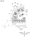
- FIG. 3 is a schematic cross-sectional view showing only the convex portion along line III-III in FIG. 1.
- the first input device 1 has a mouse operation sensor 174.
- the mouse operation sensor 174 is disposed inside the convex portion 100.
- the mouse operation sensor 174 is, for example, an optical sensor.
- the mouse operation sensor 174 has, for example, a light source 171 and a light receiving sensor 172.
- the input device 1 may also have a lens for collecting the light emitted from the light source 171 and/or the light guided to the light receiving sensor 172.
- the light source 171 emits light.
- the light may be, for example, red light, blue light, or laser light. There is no particular limitation on the wavelength of the light.
- the light from the light source 171 is irradiated onto the detection surface F from the first opening 170.
- the light receiving sensor 172 detects the reflected light from the detection surface F of the light emitted from the light source 171, which enters from the first opening 170 and changes in accordance with the relative movement of the input device 1 with respect to the detection surface F.
- the second input device 2 which will be described later, has a similar configuration.
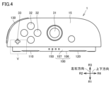
- FIG. 4 is a schematic front view showing the configuration of the input device 1 according to the first embodiment.
- FIG. 4 shows the orientation of the input device 1 when it is used as a mouse.
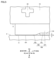
- FIG. 5 is an enlarged schematic view of region V in FIG. 4.
- the first mouse sole 191 contacts the detection surface F.
- the second mouse sole 192 also contacts the detection surface F.
- the first side button (right) 110 is spaced apart from the detection surface F.
- the top surface of the first side button (right) 110 is located on the third direction R3 side of the top surface of the first mouse sole 191.
- the detection surface F is not particularly limited, but is, for example, the surface of a desk.
- the input device 1 is movable on the detection surface F.
- the first mouse sole 191 is provided in the third top surface area 103.
- the first side button (right) 110 is provided in the first top surface area 101.
- the thickness of the part of the first mouse sole 191 protruding from the third top surface area 103 is, for example, 0.2 mm.
- the third top surface area 103 is spaced apart from the detectable surface F.
- the distance between the detectable surface F and the third top surface area 103 is, for example, 0.2 mm.
- the distance G between the detectable surface F and the operation surface of the first side button (right) 110 is, for example, 0.3 mm.
- the distance from the detectable surface F to the operation surface of the first side button (right) 110 may be longer than the distance from the detectable surface F to the third top surface area 103.
- the fourth top surface area 104 in which the second opening 196 is provided is also spaced apart from the detectable surface F.
- the input device 1 can also be used as a mouse by including a mouse operation sensor 174.
- a first opening 170 is provided on the top surface 106, which is part of the first side surface 11. Therefore, when the input device 1 is placed on the detection surface F so that the top surface 106 of the convex portion 100 faces the detection surface F, the first opening 170 is positioned close to the detection surface F. Therefore, the first opening 170 can effectively capture reflected light from the detection surface F.
- the information processing unit of the main unit 3 may calculate movement parameters (e.g., movement direction and movement distance) related to the movement of the input device 1 relative to the detection surface F.
- the main unit 3 may also execute a predetermined game process based on the movement parameters determined in the program being executed.
- the movement parameters may be calculated within the input device 1 (by the mouse operation sensor 174 or the information processing unit provided in the input device 1), and the calculated parameters may be transmitted to the main unit 3.
- the input device 1 moves relative to the detection surface F while being separated from the detection surface F, the movement of the input device 1 relative to the detection surface F may not be accurately measured.
- the input device 1 may be configured such that when the top surface 106 of the convex portion 100 is separated from the detection surface F by 1 cm or more, 5 mm or more, or 1 mm or more, the reflected light from the detection surface F for measuring the movement relative to the detection surface F cannot be properly detected.
- the mouse operation sensor 174 may be designed so that the distance from the detection surface F of the input device 1 at which the direction and distance of movement of the input device 1 relative to the detection surface F can be accurately detected is within 1 cm, or within 5 mm, or within 1 mm.
- FIG. 6 is a six-sided schematic diagram showing the configuration of the second input device.
- the second input device 2 is, for example, a game controller, and includes a joystick 41, which is an example of a directional input section, and a set of four buttons 42 arranged in a cross shape.
- the input device 1 includes a + button 33(1) and a home button 33(2)
- the second input device 2 includes a - button 43(1) and a capture button 43(2).
- the second input device 2 has a first top button (left) 240, a second top button (left) 230, a first side button (left) 210, and a second side button (left) 220.
- the first top button (left) 240 and the second top button (left) 230 are provided on the main body housing 20. In the up-down direction, the lower end of the first top button (left) 240 is provided between the upper and lower ends of the stick 41.
- the first side button (left) 210 and the second side button (left) 220 are provided on the convex portion 200.
- the second input device 2 has a light emitting unit 250, a second terminal 260 connected to the main body second terminal 341 of the main body device 3, a first opening 270 for guiding light to the mouse operation sensor 274, a first mouse sole 253, a second mouse sole 254, and an operation unit 282 constituting a removal mechanism for removing the convex portion 200 from the main body device 3.
- the structure and function of each component are substantially the same as those of the input device 1. However, some functions may be different.
- the capture button 43(2) may be used to save an image output to the display 305.
- the positional relationship between the joystick 31 and the four buttons 32 in the first input device 1 is the same as the positional relationship between the joystick 41 and the four buttons 42 in the second input device 2 (see FIG. 29). That is, in the horizontally held state, the joystick 31 is located to the left of the four buttons 32 in the first input device 1. Similarly, in the horizontally held state, the joystick 41 is located to the left of the four buttons 42 in the second input device 2. Meanwhile, in the horizontally held state, the second top button (right) 130 and the first top button (right) 140 are on the right side in the first input device 1, while the second top button (left) 230 and the first top button (left) 240 are on the left side in the second input device 2.
- the joystick 31 in the first input device 1 is located below the four buttons 32, while the joystick 41 in the second input device 2 is located above the set of four buttons 42 (Fig. 30).
- the second top button (right) 130 and first top button (right) 140 of the first input device 1 and the second top button (left) 230 and first top button (left) 240 of the second input device 2 are both on the upper side.
- the input device can be said to be an input device set including a first input device 1 and a second input device 2.
- the first input device 1 is a right-handed input device that has a directional input section 31 on the front surface 15 and a first opening 170 on the first side surface 11 located on the left side of the front surface 15.
- the second input device 2 is a left-handed input device that has a directional input section 41 on the front surface 215 and a first opening 270 on the first side surface located to the right of the front surface 215.
- Figure 7 is a schematic front view showing an example of the configuration of the information processing device 1000.
- the information processing device 1000 has a first input device 1, a second input device 2, and a main unit 3.
- the first input device 1 or the second input device 2 will be collectively referred to simply as a game controller.
- the main unit 3 has a roughly rectangular parallelepiped shape, with the upper and lower sides being longer than the right and left sides.
- the main unit 3 is capable of executing game processing.
- the game processing is executed based on an input to the game controller.
- the first input device 1 and the second input device 2 are detachable from the main unit 3.
- the input device 1 is attached to the right side of the main unit 3, and the second input device 2 is attached to the left side of the main unit 3.
- the first input device 1 is fixed to the second input device 2 via the main unit 3. In other words, the first input device 1 is indirectly fixed to the second input device 2.
- the first input device 1 may be indirectly fixed to the second input device 2 via a device different from the main body device 3. In another embodiment, the first input device 1 may be directly fixed to the second input device 2.
- the first input device 1 is fixed directly or indirectly to the second input device 2.
- the first input device 1 and the second input device 2 fixed to each other may be used as an integrated game controller.
- various information including operation information of the input unit is transmitted to the main unit first terminal 331 of the main unit 3 through the first terminal 160 described later, and the information is processed according to a program by the CPU (Central Processing Unit) of the main unit 3.
- CPU Central Processing Unit
- various information including operation information of the input unit is transmitted to the CPU of the main unit 3 via a wireless chip provided in the game controller and a wireless chip provided in the main unit 3.
- information may be transmitted via the wireless chip.
- the information processing device 1000 does not need to have at least one of the first terminal 160 and the main unit first terminal 331.
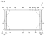
- FIG. 8 is a schematic front view showing the configuration of an example of the main unit 3.
- the main unit 3 has a main housing 306, a first plug connector 330, a second plug connector 340, a first magnetic element 410, a second magnetic element 420, a third magnetic element 430, and a fourth magnetic element 440.
- the main body device 3 has a recess 310 on the main body right side surface 313.
- the recess 310 is composed of a first recess bottom surface 311 and a first recess side surface 312.
- the recess 310 extends in the longitudinal direction of the main body right side surface 313.
- the recess 310 extends along the vertical direction of the main body right side surface 313.
- the main body left side surface 314 of the main body device 3 has a recess 320.
- the recess 320 is composed of a second recess bottom surface 321 and a second recess side surface 322.
- the recess 320 extends in the longitudinal direction of the main body left side surface 314.
- the recess 320 extends along the vertical direction of the main body left side surface 314 of the main body device 3.
- the first input device 1 is attached to the main body device 3 so that the convex portion 100 fits into the recess 310.
- the first input device 1 is attached to the main body device 3 so that the first side surface 11 of the first input device 1 faces the main body right side surface 313 of the main body device 3 and the longitudinal direction of the first side surface 11 of the first input device 1 is aligned with the longitudinal direction of the main body right side surface 313 of the main body device 3.
- the second input device 2 is attached to the main body device 3 so that the convex portion 200 fits into the recess 320.
- the second input device 2 is attached to the main body left side surface 314 of the main body device 3.
- a display 305 is provided on the main body front 315 of the main body device 3.
- the display surface of the display 305 is exposed through an opening provided on the main body front 315.
- the display 305 may be placed on the surface of the main body front 315.
- the display 305 may be any display device, such as a liquid crystal display device or an OLED.
- a touch panel may be provided on the display surface of the display 305. Any touch detection method may be adopted for the touch panel.
- the display 305 displays, for example, an image acquired or generated by the main body device 3.
- the image may be a still image or a video.
- the main unit 3 has an audio input/output terminal 301.
- the audio input/output terminal 301 is provided on the upper side 316 of the main unit 3.
- the audio input/output terminal 301 is, for example, an earphone jack. Earphones and a microphone can be attached to the audio input/output terminal 301.
- the main unit 3 may also have a volume button next to the audio input/output terminal 301.
- the volume button is a button for issuing instructions to adjust the volume output by the main unit 3.
- the main unit 3 has a lower terminal 303.
- the lower terminal 303 is provided on a lower surface 317 of the main unit 3.
- the lower terminal 303 may be provided in the center in the left-right direction on the lower surface 317 of the main unit.
- the lower terminal 303 is, for example, a terminal for communicating with an external device.
- the lower terminal 303 constitutes, for example, a USB (Universal Serial Bus) connector.
- the main unit 3 may receive power from the outside via the lower terminal 303.
- the main unit 3 may output images to the outside via the lower terminal 303.
- the main unit 3 has an upper terminal 302, a power button 307, and a storage medium slot 304.
- the upper terminal 302, the power button 307, and the storage medium slot 304 are provided on the upper side 316 of the main unit.
- the main unit 3 may execute game processing by executing a game application stored on a storage medium inserted into the storage medium slot 304.
- the left side 314 of the main body is opposite to the right side 313 of the main body with respect to the front of the main body device 3.
- the left side 314 of the main body is configured similarly to the right side 313 of the main body.
- the recess 310 is provided with a first plug connector 330, a first magnetic element 410, and a second magnetic element 420.
- the first magnetic element 410 and the second magnetic element 420 include magnets.
- the first plug connector 330 is disposed between the first magnetic element 410 and the second magnetic element 420.
- the recess 320 is provided with a second plug connector 340, a third magnetic element 430, and a fourth magnetic element 440.
- the third magnetic element 430 and the fourth magnetic element 440 include magnets.
- the second plug connector 340 is disposed between the third magnetic element 430 and the fourth magnetic element 440.
- the protrusion 100 is shaped to fit into each of the recesses 310 and 320.
- the protrusion 200 is shaped to fit into each of the recesses 310 and 320.
- the recess 310 may be substantially symmetrical with respect to the longitudinal direction of the recess 310.
- the recess 320 may be substantially symmetrical with respect to the longitudinal direction of the recess 320.
- the protrusion 100 may be substantially symmetrical with respect to the longitudinal direction of the protrusion 100.
- the protrusion 200 may be substantially symmetrical with respect to the longitudinal direction of the protrusion 200.
- the longitudinal direction of recess 310 may be parallel to the longitudinal direction of recess 320. Each of the longitudinal directions of recess 310 and recess 320 may be parallel to the up-down direction.
- the width direction of recess 310 may be parallel to the width direction of recess 320. Each of the width directions of recess 310 and recess 320 may be parallel to the front-rear direction.
- FIG. 9 is a schematic perspective view showing the configuration of the right side of the main unit 3. Note that the main unit 3 also has a similar configuration on the left side.
- the first plug connector 330 has a tongue body 332 and a main body first terminal 331.
- the main body first terminal 331 is provided along the surface of the tongue body 332.
- a recess 310 is provided on the main body right side surface 313 of the main body device 3.
- the recess 310 is a recessed portion on the main body right side surface 313.
- the recess 310 extends in the longitudinal direction of the main body right side surface 313.
- the front side edge and the rear side edge of the first recess bottom surface 311 of the recess 310 are each substantially straight and extend substantially parallel.
- the upper and lower regions of the first recess bottom surface 311 each narrow in width toward the end.
- the upper and lower regions of the first recess bottom surface 311 narrow in width in a curved shape.
- the first magnetic element 410 and the second magnetic element 420 are arranged so as not to be exposed from the first recess bottom surface 311.
- the first magnetic element 410 and the second magnetic element 420 may be covered by a cover, one surface of which forms the first recess bottom surface 311.
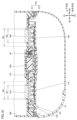
- FIG. 10 is a schematic cross-sectional view showing the first input device 1 attached to the main unit 3.
- the schematic cross-sectional view shown in FIG. 10 is parallel to both the up-down direction and the left-right direction.
- the convex portion 100 of the first input device 1 fits into the recess 310 of the main unit 3.
- the first side button (right) 110 is attracted to the first magnetic element 410 by magnetic force. At this time, the first side (right) 110 moves leftward so as to approach the first magnetic element 410.
- the position of the top surface of the first side button (right) 110 in the left-right direction may be the same as the maximum height position of the top surface 106 of the convex portion 100, or may be on the first direction R1 side of the maximum height position.
- the length of the top surface of the first side button (right) 110 third length W3 may be longer than the length of the first magnetic element 410 (first length W1).
- the second side button (right) 120 is attracted to the second magnetic element 420 by magnetic force. At this time, the second side (right) 120 moves leftward so as to approach the second magnetic element 420.
- the position of the top surface of the second side button (right) 120 in the left-right direction may be the same as the maximum height position of the top surface 106 of the convex portion 100, or may be on the first direction R1 side of the maximum height position.
- the length of the top surface of the second side button (right) 120 (fourth length W4) may be longer than the length of the second magnetic element 420 (second length W2).
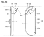
- FIG. 11 is a schematic diagram showing the state before the ejection lever is operated.
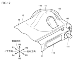
- FIG. 12 is a schematic diagram showing the state when the ejection lever is operated.
- the first input device 1 has a pusher 181, an eject operation lever 182, and a biasing portion 183. These constitute a removal mechanism.
- the pusher 181 protrudes from the top surface 106 of the protruding portion 100.
- the protruding pusher 181 presses the first recess bottom surface 311 of the recess 310.
- the top surface 106 of the protruding portion 100 moves in a direction away from the first recess bottom surface 311.
- the first input device 1 rotates around the end opposite to the end where the pusher 181 is provided as a fulcrum. As described above, the first input device 1 can be easily removed from the main unit 3.
- the pusher 181 may protrude above the operating part 182 in the longitudinal direction of the protrusion 100.
- the center of the pusher 181 may be located above the center of the ejection operating lever 182 in the longitudinal direction of the protrusion 100.
- the amount of protrusion of the pusher 181 may be such that the operation surface of the first side button (right) 110 is separated from the bottom surface 311 of the first recess by the protrusion of the pusher 181. From another perspective, the amount of protrusion of the pusher 181 may be such that the operation surface of the first side button (right) 110 is separated from the bottom surface 311 of the first recess even when the first side button (right) 110 is attracted to the first magnetic element 410 and moves upward to the maximum extent. This allows the first input device 1 to be easily removed from the main unit 3.
- the amount of protrusion of the pusher 181 may be such that at least a part of the operation surface of the second side button (right) 120 does not separate from the bottom surface 311 of the first recess. This prevents the first input device 1 from being suddenly removed from the main unit 3.
- the amount of protrusion of the pusher 181 may be such that the upper end of the top surface 106 of the convex portion 100 (the end on the second direction R2 side in FIG. 11 ) is exposed from the opening of the recess 310 when the pusher 181 protrudes.
- the amount of protrusion of the pusher 181 may be such that the upper end of the top surface 106 is not exposed from the opening of the recess 310 even when the pusher 181 protrudes.
- the amount of protrusion of the pusher 181 may be such that the light emitting portion 150 provided on the outer peripheral surface 107 is not exposed from the opening of the recess 310 even when the pusher 181 protrudes.
- the amount of protrusion of the pusher 181 may be such that the upper end of the first side surface 11 (the end on the second direction R2 side in FIG. 11 ) and the upper end of the main body right side surface 313 are separated by a distance of, for example, 0.5 mm to 1 cm when the pusher 181 protrudes.
- the distance may be, for example, 1 mm to 5 mm.
- the separation distance may be, for example, 2 mm.
- the eject operation lever 182 is provided on the rear surface 16.
- the eject operation lever 182 is pushed from the first side surface 11 toward the second side surface 13. More specifically, the eject operation lever 182 rotates in a direction from the first side surface 11 toward the second side surface 13 and from the rear surface 16 toward the front surface 15.
- the rear surface 16 has a protrusion 18.
- the protrusion 18 is located on the third direction R3 side relative to the eject operation lever 182.
- the protrusion 18 protrudes in the sixth direction R6 from the rear surface 16.
- the eject operation lever 182 does not have to be entirely buried. When the eject operation lever 182 is operated to its limit, a part of the eject operation lever 182 may protrude from the protruding portion 18. The maximum height of the eject operation lever 182 from the rear surface 16 when not operated is lower than the maximum height of the eject operation lever 18 from the rear surface 16 of the protruding portion 18. The rear end of the eject operation lever 182 when not operated may be located forward of the rear end of the protruding portion 18 from the rear surface 16. When the first input device 1 is placed on the detected surface F such that the first side surface 11 faces the detected surface F, the end of the protruding portion 18 is grounded, while the eject operation lever 182 is prevented from contacting the detected surface F.
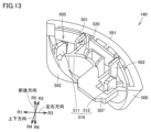
- Figure 13 is a schematic perspective view showing the configuration of the first top button (right) 140.
- the first top button (right) 140 has a first body portion 500, a bearing 520, a misalignment prevention rib 510, and a pressing portion 507.
- the first top button (right) 140 has a first plate-shaped portion 501 and a second plate-shaped portion 502.
- the first plate-shaped portion 501 and the second plate-shaped portion 502 each protrude in a direction that includes a component of the fifth direction R5.
- the first plate-shaped portion 501 is disposed opposite the second plate-shaped portion 502.
- the misalignment prevention rib 510 has a first rib portion 511 and a second rib portion 512. Each of the first rib portion 511 and the second rib portion 512 protrudes from the first main body portion 500 in a direction that includes a component of the fifth direction R5.
- the first main body portion 500 has a first outer surface 591 and a first inner surface 592.
- the first outer surface 591 includes a surface that is operated by a user.
- the first outer surface 591 is located outside the main body housing 10 when the first top button (right) 140 is attached to the main body housing 10.
- the first inner surface 592 is on the opposite side of the first outer surface 591.
- the first inner surface 592 is located inside the main body housing 10 when the first top button (right) 140 is attached to the main body housing 10.
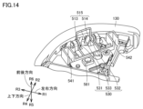
- the first input device 1 has a first rotation shaft 515, a third biasing portion 530, a first switch 581, a first rib accommodating portion 541, and a second rib accommodating portion 542.
- the first rotation shaft 515 is formed, for example, by a part of the main body housing 10.
- the first rotation shaft 515 has a third shaft 513 and a fourth shaft 514.
- the fourth shaft 514 is spaced apart from the third shaft 513.
- the fourth shaft 514 and the third shaft 513 are positioned on the same straight line.
- the direction in which the first rotation shaft 515 extends is also referred to as the first rotation axis direction.
- the first switch 581 is, for example, a tactile switch. In another embodiment, the first switch 581 may be a rubber switch. The first switch 581 may be located near the third shaft 513 in the first rotation axis direction. From another perspective, the first switch 581 may be located closer to the third shaft 513 than the midpoint between the third shaft 513 and the fourth shaft 514.
- the third biasing portion 530 biases the first top button (right) 140.
- the third biasing portion 530 is, for example, a double torsion spring.
- the third biasing portion 530 has a first coil spring portion 531, a central connection portion 533, and a second coil spring portion 532.
- the central connection portion 533 connects the first coil spring portion 531 and the second coil spring portion 532.
- the central connection portion 533 is located between the first coil spring portion 531 and the second coil spring portion 532.
- the first coil spring portion 531 is attached to the third shaft 513.
- the second coil spring portion 532 is attached to the fourth shaft 514.
- Each of the first rib accommodating portion 541 and the second rib accommodating portion 542 is formed, for example, by a part of the main housing 10.
- Each of the first rib accommodating portion 541 and the second rib accommodating portion 542 extends in the front-rear direction. When viewed in the front-rear direction, each of the first rib accommodating portion 541 and the second rib accommodating portion 542 is substantially C-shaped. From another perspective, each of the first rib accommodating portion 541 and the second rib accommodating portion 542 has a portion of its circumferential surface that is open.
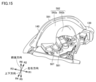
- FIG. 15 is a schematic perspective view showing the state in which the first top button (right) 140 is attached to the configuration shown in FIG. 14.
- the first inner surface 592 has a first side region 592a and a second side region 592b.
- the second side region 592b is continuous with the first side region 592a.
- the second side region 592b is recessed further than the first side region 592a.
- the second side region 592b is recessed toward the first outer surface 591.
- a part of the eject operation lever 182 may be positioned in the recess formed by the second side region 592b (see FIG. 12).
- the first top button (right) 140 has a pressing portion 507.
- the pressing portion 507 is connected to the first side region 592a.
- the pressing portion 507 protrudes from the first side region 592a.
- the pressing portion 507 is disposed on the first switch 581.
- FIG. 16 is a first schematic cross-sectional view showing a part of the internal structure of the first input device.
- the cross section shown in FIG. 16 is a cross section seen from the rear when the first input device 1 is placed on the detection surface F, and is parallel to the up-down direction and the left-right direction.
- the first rib portion 511 is accommodated in the first rib accommodating portion 541.
- the second rib portion 512 is accommodated in the second rib accommodating portion 542.
- Each of the first rib portion 511 and the second rib portion 512 extends in a direction approximately perpendicular to the direction in which the first rotation shaft 515 extends.
- the third shaft 513 is located between the first rib portion 511 and the fourth shaft 514.
- the fourth shaft 514 is located between the second rib portion 512 and the third shaft 513.
- the first rotation shaft 515 extends in a direction that includes a left-right component. Specifically, the first rotation shaft 515 extends in a direction that includes a left-right component and an up-down component.
- the direction in which the first rotation shaft 515 extends may be parallel to the left-right direction, or may be inclined relative to the left-right direction.
- the direction in which the first rotation shaft 515 extends is, for example, inclined relative to both the left-right direction and the up-down direction.
- the bearing 520 has a first bearing portion 521 and a second bearing portion 522.
- the first bearing portion 521 is a notch provided in the first plate-shaped portion 501.
- the second bearing portion 522 is a notch provided in the second plate-shaped portion 502.
- the second bearing portion 522 is disposed opposite the first bearing portion 521.
- the third shaft 513 is disposed in the first bearing portion 521.
- the first bearing portion 521 rotatably supports the third shaft 513.
- the fourth shaft 514 is disposed in the second bearing portion 522.
- the second bearing portion 522 rotatably supports the fourth shaft 514.
- the first rotation axis 515 may be configured to be inclined downward of the first input device 1 with respect to a direction perpendicular to the detection surface F when the first side surface 11 is placed on the detection surface F.
- the angle between the detection surface F and the first rotation axis 515 when the first side surface 11 is placed on the detection surface F is defined as a first angle ⁇ 1.
- the first angle ⁇ 1 corresponds to the angle between the detection surface F and a first straight line L1 along the first rotation axis 515.
- the first angle ⁇ 1 is, for example, 45°. In one embodiment, the first angle ⁇ 1 may be smaller than 45°. In another embodiment, the first angle ⁇ 1 may be larger than 45°.
- the first angle ⁇ 1 is an acute angle greater than 0 and less than 90°. In another embodiment, the first angle ⁇ 1 may be 90°.
- the first rotation shaft 515 may extend along a plane parallel to the front surface 15. In this embodiment, the first rotation shaft 515 extends along a plane perpendicular to the front-rear direction. From another perspective, the first rotation shaft 515 extends in a direction parallel to the plane in which the second top button (right) 130 can move. In another aspect, the first rotation shaft 515 may extend along a plane inclined with respect to a plane perpendicular to the front-rear direction. In other words, the first rotation shaft 515 may extend along a plane inclined with respect to planes parallel to each of the up-down direction and the left-right direction.
- FIG. 17A is a schematic cross-sectional view showing the positional relationship between the first top surface button (right) 140 and the first switch 581 before the user operates the first top surface button (right) 140.
- the cross section shown in FIG. 17A is perpendicular to the direction in which the first rotation axis 515 extends.
- the pressing portion 507 of the first top surface button (right) 140 does not press down the first switch 581.
- the pressing portion 507 may be separated from the first switch 581.
- FIG. 17B is a schematic cross-sectional view showing the positional relationship between the first top surface button (right) 140 and the first switch 581 after the user operates the first top surface button (right) 140.
- the cross section shown in FIG. 17B is perpendicular to the direction in which the first rotation axis 515 extends.
- the pressing portion 507 of the first top surface button (right) 140 presses the first switch 581.
- the pressing portion 507 comes into contact with the first switch 581.
- an input is made to the first switch 581.
- a load equal to or greater than a certain threshold is applied to the first switch 581, the first switch 581 is turned on.
- the first top button (right) 140 is pressed by the user.
- the pressing direction (first arrow direction S1) of the first top button (right) 140 includes a component from the top surface 12 toward the bottom surface 14.
- the pressing direction (first arrow direction S1) of the first top button (right) 140 includes a forward component, a downward component, and a leftward component.
- the first top button (right) 140 can be pressed around the first rotation axis 515. When pressed by the user, the first top button (right) 140 rotates around the first rotation axis 515.
- the movable angle of the first top button (right) 140 is not particularly limited, but may be, for example, 20° or less, 15° or less, or 10° or less.
- the first top surface button (right) 140 is biased by the third biasing portion 530. When the user releases the first top surface button (right) 140, the first top surface button (right) 140 returns to its original position.
- the pressing portion 507 of the first top surface button (right) 140 may be separated from the first switch 581. This ends the input to the first switch 581, and the first switch 581 becomes OFF.
- the input device 1 has a first top surface button (right) 140. Therefore, in a first usage state in which the front surface 15 faces forward and the top surface 12 faces upward, the input device 1 can be used like a game controller.
- the first top surface button (right) 140 can also be pressed around a first rotation axis 515 that extends in a direction that includes left-right components. Therefore, in the first usage state, the first top surface button (right) 140 can be easily pressed downward with the index finger or middle finger when used as a shoulder button.
- the input device 1 has a mouse operation sensor 174. Therefore, in the second use state in which the input device 1 is placed on the detection surface F with the first side surface 11 facing downward, the input device 1 can be used as a mouse. That is, the user can use the input device 1 as a mouse by moving the input device 1 on the detection surface F with the first side surface 11 facing the detection surface F.
- the first upper surface button (right) 140 can be used like a click button.
- the first rotation axis 515 extends in a direction away from the detection surface F. Therefore, as in the first use state, the first upper surface button (right) 140 can be pressed downward with the index finger or middle finger, making it easy to operate the input device 1.
- the input device 1 it is possible to use it like a game controller and as a mouse. Furthermore, because the first top button (right) 140 rotates around the first rotation axis 515, it has good operability as a shoulder button when used as a game controller, and does not impair operability as a click button when used as a mouse. Note that the input device 1 may stand on its own on the detection surface F with the first side surface 11 facing downwards, without the user having to support it.
- first rotation axis 515 may be configured so that when the first side surface 11 is placed on the detection surface F, the direction is inclined toward the lower side of the input device 1 with respect to a direction perpendicular to the detection surface F. This makes it easier to perform a click operation since the first top surface button (right) 140 can be pressed down in a direction toward the detection surface F when operating the mouse.
- the acute angle formed by the detection surface F and the first rotation axis 515 may be greater than 45°. This makes it easier to press the first top surface button (right) 140 when holding the input device 1 in a lifted-up state.
- the hand is placed so that the fingers hook over the top surface in order to press the first top surface button (right) 140, so even if the acute angle is greater than 45°, the first top surface button (right) 140 can be easily pressed by bending the fingers.
- the angle between the detection surface F and the first rotation axis 515 may be 45°. This makes it easier to press the first top surface button (right) 140 when holding the input device 1 in a lifted-up state or when operating a mouse.
- the first rotation axis 515 may be aligned along a plane perpendicular to the detection surface F. This makes it easier to press the first top button (right) 140 when using the input device 1 as a mouse.
- Figure 19 is a schematic perspective view showing the configuration of the second top button (right) 130.
- the second top button (right) 130 has a second main body portion 553, a first flange portion 551, a second flange portion 552, and a second outer surface 131.
- the second main body portion 553 is provided with a first shaft hole 138 and a second shaft hole 137.
- the second shaft hole 137 is spaced apart from the first shaft hole 138.
- the first shaft hole 138 and the second shaft hole 137 are provided on a side surface different from the second outer surface 131.
- the first shaft hole 138 is, for example, a through hole.
- the first shaft hole 138 may be a bottomed hole.
- the second shaft hole 137 is, for example, a through hole.
- the second shaft hole 137 may be a bottomed hole.
- the second outer surface 131 is the surface that is operated by the user.
- the second outer surface 131 is curved so as to be convex outward.
- the second outer surface 131 is constituted by a second main body portion 553.
- the first flange portion 551 is provided on one side of the second main body portion 553.
- the second flange portion 552 is provided on the other side of the second main body portion 553.
- the second main body portion 553 is between the first flange portion 551 and the second flange portion 552.
- FIG. 20 is a second schematic cross-sectional view showing a part of the internal structure of the first input device 1.
- the cross section shown in FIG. 20 is parallel to the up-down and left-right directions.
- the input device 1 has a first biasing member 141, a second biasing member 142, and a second switch 143.
- the second top button (right) 130 has a second inner surface 132, a third protrusion 133, a fourth protrusion 134, and a fifth protrusion 135.
- the second outer surface 131 is, for example, arc-shaped.
- the second inner surface 132 is on the opposite side to the second outer surface 131.
- the first input device 1 has an internal component 148.
- the second inner surface 132 faces the internal component 148.
- the third protrusion 133 is provided on the second inner surface 132.
- the third protrusion 133 protrudes from the second inner surface 132 in the fourth direction R4.
- the fourth protrusion 134 is provided on the second inner surface 132.
- the fourth protrusion 134 protrudes from the second inner surface 132 in the fourth direction R4. In the left-right direction, the fourth protrusion 134 is located closer to the first direction R1 than the third protrusion 133.
- the fifth protrusion 135 is provided on the second inner surface 132.
- the fifth protrusion 135 protrudes from the second inner surface 132 in the fourth direction R4.
- the fifth protrusion 135 is located closer to the first direction R1 than the third protrusion 133 and closer to the third direction R3 than the fourth protrusion 134.
- the fifth protrusion 135 is located between the third protrusion 133 and the fourth protrusion 134.
- the length of the fifth protrusion 135 may be longer than the length of the third protrusion 133.
- the length of the fifth protrusion 135 may be longer than the length of the fourth protrusion 134.
- the fifth protrusion 135 may be located between the third protrusion 133 and the fourth protrusion 134.
- the first biasing member 141 biases the second top button (right) 130 upward.
- the first biasing member 141 is, for example, a coil spring.
- the first biasing member 141 is supported by the internal part 148.
- the first biasing member 141 extends, for example, along the up-down direction.
- the end of the first biasing member 141 on the second direction R2 side is attached, for example, to the fourth protrusion 134.
- the end of the first biasing member 141 on the fourth direction R4 side is attached, for example, to the first part 145 of the internal part 148.
- the second biasing member 142 biases the second top button (right) 130 upward.
- the second biasing member 142 is, for example, a coil spring.
- the second biasing member 142 is supported by the internal part 148.
- the second biasing member 142 extends, for example, along the up-down direction.
- the end of the second biasing member 142 on the second direction R2 side is attached, for example, to the third protrusion 133.
- the end of the second biasing member 142 on the fourth direction R4 side is attached, for example, to the second part 146 of the internal part 148.
- the second biasing member 142 is located closer to the third direction R3 than the first biasing member 141.
- the fifth protrusion 135 is located between the second biasing member 142 and the first biasing member 141.
- the second biasing member 142 is located closer to the fourth direction R4 than the first biasing member 141.
- the fifth protrusion 135 may be located between the second biasing member 142 and the first biasing member 141.
- the second top button (right) 130 can be pressed in a linear direction. Specifically, the second top button (right) 130 can be pressed in the second arrow direction S2.
- the second arrow direction S2 is, for example, the fourth direction R4.
- the first biasing member 141 and the second biasing member 142 bias the second top button (right) 130 upward. Therefore, when the user stops pressing the second top button (right) 130, the second top button (right) 130 moves in the second direction R2.
- the second top button (right) 130 can be moved along the vertical direction.
- the second top button (right) 130 may be pressed along a straight line along the vertical direction, or may be pressed along a straight line inclined with respect to the vertical direction.
- the second switch 143 is activated when the second top button (right) 130 is pressed.
- the second switch 143 is, for example, a tactile switch.
- the second switch 143 may be, for example, a rubber switch. The second switch 143 is pressed by the second top button (right) 130.
- the second switch 143 is supported by the third portion 147 of the internal component 148.
- the second switch 143 is arranged so as to be in contact with the fifth protrusion 135, for example.
- the second top button (right) 130 presses the second switch 143.
- the fifth protrusion 135 of the second top button (right) 130 presses the second switch 143. This causes an input to be made to the second switch 143.
- a load equal to or greater than a certain threshold is applied to the second switch 143, the second switch 143 turns on.
- the first biasing member 141 and the second biasing member 142 each push up the second button 32(2). This causes the second top button (right) 130 to return to its original position.
- the fifth protrusion 135 of the second top button (right) 130 may move away from the second switch 143. This ends the input to the second switch 143, and the second switch 143 turns off.
- the second switch 143 is located, for example, between the first biasing member 141 and the second biasing member 142. In the left-right direction, the second switch 143 is located between the third protrusion 133 and the fourth protrusion 134. In the up-down direction, the second switch 143 is located between the fifth protrusion 135 and the third part 147 of the internal component 148.
- the third portion 147 has a support surface 149 of the second switch 143.
- the support surface 149 is a surface on which the third portion 147 supports the second switch 143.
- the support surface 149 of the second switch 143 is configured to be inclined toward the lower side of the input device 1 with respect to a direction perpendicular to the detected surface F when the first side surface 11 is placed on the detected surface F.
- the angle between the detected surface F and the support surface 149 when the first side surface 11 is placed on the detected surface F is the second angle ⁇ 2.
- the second angle ⁇ 2 corresponds to the angle between the second straight line L2 along the support surface 149 and the detected surface F.
- the second angle ⁇ 2 may be, for example, greater than 45°.
- the second angle ⁇ 2 may be, for example, greater than 60° or greater than 65°.
- the second angle ⁇ 2 may be less than 90°.
- the second angle ⁇ 2 is not particularly limited, but may be, for example, 85° or less, or 80° or less.
- the first flange portion 551 faces the inner wall of the front housing 61.
- the first flange portion 551 is prevented from coming off by the inner wall of the front housing 61.
- the second flange portion 552 is located closer to the fourth direction R4 than the first flange portion 551.
- the second flange portion 552 faces the inner wall of the front housing 61.
- the second flange portion 552 is prevented from coming off by the inner wall of the front housing 61.
- FIG. 21 is a third schematic cross-sectional view showing a part of the internal structure of the first input device.
- the schematic cross-sectional view shown in FIG. 21 is parallel to both the up-down direction and the left-right direction, and is a schematic cross-sectional view on the front side of the schematic cross-sectional view shown in FIG. 21.
- the first input device 1 has a first axis 81 and a second axis 82.
- the first axis 81 (second rotation axis 81) extends along a direction including a component in the front-rear direction, for example.
- the direction in which the first axis 81 extends may be parallel to the front-rear direction, or may be inclined with respect to the front-rear direction. From another perspective, the first axis 81 extends in a direction parallel to the detection surface F when the first side surface 11 or the second side surface 13 is placed on the detection surface F.
- the second axis 82 extends along a direction including a component in the front-rear direction, for example.
- the direction in which the first axis 81 extends may be parallel to the direction in which the second axis 82 extends.
- each of the first axis 81 and the second axis 82 is provided between the first side surface 11 and the second side surface 13.
- the first axis 81 is provided between the first side surface 11 and the second axis 82.
- the second shaft 82 is provided between the first shaft 81 and the second side surface 13.
- Each of the first shaft 81 and the second shaft 82 is formed, for example, by the front housing 61.
- the first shaft 81 and the second shaft 82 have the same diameter, but may have different diameters.
- the diameter of the first shaft 81 may be larger than the diameter of the second shaft 82.
- the first shaft 81 is disposed in the first shaft hole 138.
- the second shaft 82 is disposed in the second shaft hole 137.
- the first shaft 81 overlaps with the first biasing member 141.
- the second shaft 82 overlaps with the second biasing member 142.
- the width of the first shaft hole 138 in the left-right direction is defined as first shaft hole width D1.
- the width of the second shaft hole 137 in the left-right direction is defined as second shaft hole width D2.
- the second shaft hole width D2 is longer than the first shaft hole width D1.
- the width of the second shaft hole 137 is longer than the diameter of the second shaft 82.
- the second top button (right) 130 rotate around the first shaft 81.
- the movement of the second top button (right) 130 can be determined to some extent.
- the width of the first shaft hole 138 is longer than the diameter of the first shaft 81, and the width of the second shaft hole 137 is longer than the diameter of the second shaft 82, so the second top button (right) 130 can be pushed in a straight line.
- the second shaft hole 137 is provided on the opposite side of the first side surface 11 in the left-right direction from the first shaft hole 138. Specifically, in the left-right direction, the second shaft hole 137 is provided between the first shaft hole 138 and the second side surface 13. In the left-right direction, the first shaft hole 138 is provided between the first side surface 11 and the second shaft hole 137.
- FIG. 22 is a schematic cross-sectional view showing a state in which the second top surface button (right) 130 has rotated around the first axis 81.
- the second top surface button (right) 130 can rotate around the first axis 81.
- the second top surface button (right) 130 is pressed by a user.
- the second top surface button (right) 130 is pressed in the third arrow direction S3.
- the third arrow direction S3 includes a leftward component and a downward component.
- the movable angle of the second top surface button (right) 130 may be, for example, 20° or less, 15° or less, or 10° or less.
- the second top button (right) 130 can be pushed in a linear direction and can rotate around the first axis 81.
- the first axis 81 can move vertically within the first axis hole 138.
- the second axis 82 can move vertically within the second axis hole 137.
- the first axis 81 moves vertically within the first axis hole 138, and the second axis 82 moves vertically within the second axis hole 137.
- the second top button (right) 130 rotates, the first axis 81 stops within the first axis hole 138, and the second axis 82 moves horizontally within the second axis hole 137.
- the second top button (right) 130 can also move linearly and rotate at the same time.
- the second top button (right) 130 has been described as having a first shaft hole 138 and a second shaft hole 137, but the present disclosure is not limited to this aspect.
- the second top button (right) 130 may have a first shaft 81 and a second shaft 82.
- the front housing 61 has a first shaft hole 138 in which the first shaft 81 is disposed, and a second shaft hole 137 in which the second shaft 82 is disposed.
- the second top button (right) 130 may have a first shaft 81 and a second shaft hole 137.
- the front housing 61 has a first shaft hole 138 in which the first shaft 81 is disposed, and a second shaft 82 disposed in the second shaft hole 137.
- the second top button (right) 130 may have a first shaft hole 138 and a second shaft 82.
- the front housing 61 has a first shaft 81 disposed in the first shaft hole 138 and a second shaft hole 137 in which the second shaft 82 is disposed.
- the second top button (right) 130 may have either the first shaft hole 138 or the first shaft 81 arranged in the first shaft hole 138, and either the second shaft hole 137 or the second shaft 82 arranged in the second shaft hole 137.
- the input device 1 other than the second top button (right) 130 may have the other of the first shaft hole 138 or the first shaft 81, and the other of the second shaft hole 137 or the second shaft 82.
- the input device 1 other than the second top button (right) 130 may be the front housing 61, may be an internal component 148, or may be some other member.
- the first shaft 81 may be part of the front housing 61.
- the first shaft 81 extends along the front-rear direction. In the front-rear direction, the first shaft 81 is located between the first biasing member 141 and the front surface 15.
- the second top button (right) 130 is biased in the second direction R2. In the up-down direction, the lower end of the first shaft 81 comes into contact with the surface that constitutes the first shaft hole 138 of the second top button (right) 130, preventing the second top button (right) 130 from coming off.
- the internal component 148 is located between the front housing 61 and the rear housing 62.
- the second top button (right) 130 may be sandwiched between the front housing 61 and the rear housing 62.
- the first biasing member 141 is located between the front housing 61 and the rear housing 62.
- FIG. 24 is a schematic perspective view showing the input device 1 held vertically.
- the user holds the first input device 1 with his right hand and the second input device 2 with his left hand.
- the user can operate the first top button (right) 140 and the second top button (right) 130 with the index finger of his right hand.
- the user may operate the first top button (right) 140 and the second top button (right) 130 with the middle finger of his right hand.
- the user can operate the input section on the front with the thumb of his right hand.
- the user can operate the joystick 31, the + button 33(1), and the set of four buttons 32 with the thumb.
- the first top button (left) 240, the second top button (left) 230, the joystick 41, the - button 43(1), and the set of four buttons 42 are operated by the user's left hand in the same manner as by the right hand.
- the first top surface button (right) 140 of the input device 1 can be easily pressed by rotating it backward.
- the second top surface button (right) 130 can be pressed in a linear direction downward or in a rotation direction around a rotation axis extending in the front-rear direction. Therefore, the second top surface button (right) 130 is easy to operate in the front-rear direction while saving space.
- the first top surface button (right) 140 is located behind the second top surface button (right) 130, it is physically difficult to rotate the second top surface button (right) 130 backward.
- rotating the second top surface button (right) 130 forward may be difficult to operate.
- the second top surface button (right) 130 can be rotated around a second rotation axis extending in the front-rear direction. This allows the second top surface button (right) 130 to be pressed by rotating it while saving space.
- the length from the first side surface 11 to the rear end of the rear surface 16 on the opposite side of the front surface 15 may be longer in the front-rear direction than the length from the first side surface 11 to the front end of the front surface 15. Since the front surface 15 has a directional input section, the amount of protrusion (thickness) from the first side surface 11 can be reduced for ease of grip and operability when the input device 1 is held in a lifted-up state while holding the controller. On the other hand, the rear surface 16 protrudes toward the rear surface 16 so that the input device 1 can be easily gripped with fingers that have reached behind.
- the rear edge of the operation surface is positioned at the same level as or above the front edge of the operation surface of the first top surface button (right) 140 behind it. Because the second top surface button (right) 130 has a thin shape, there is a risk that the finger that falls off the button when pressed down may press the first top surface button (right) 140. However, even when pressed to the maximum, the operation surface of the second top surface button (right) 130 is positioned at the same level as or above the operation surface of the first top surface button (right) 140, preventing erroneous operation.
- FIG. 25 is a schematic front view showing the input device 1 being used as a mouse.
- FIG. 26 is a schematic side view showing the input device 1 being used as a mouse.
- the palm of the user's hand is placed so as to cover the second side surface 13 of the input device 1.
- the thumb of the user's right hand is placed on the front surface 15 side.
- the thumb of the user's right hand is placed on the joystick 31.
- the index finger of the user's right hand is placed on the second top surface button (right) 130.
- the middle finger of the user's right hand is placed on the first top surface button (right) 140.
- the user can operate the second top button (right) 130 with the index finger of his right hand.
- the user can operate the first top button (right) 140 with the middle finger of his right hand.
- the user may operate the first top button (right) 140 with the index finger of his right hand.
- the user can operate the input unit on the front with his right thumb.
- the user can operate the joystick 31, the + button 33(1), and the set of four buttons 32 with his thumb.
- the second input device 2 may also be used as a mouse with the left hand in a similar manner.
- the input device 1 has a first top button (right) 140 and a second top button (right) 130 provided in front of the first top button (right) 140. This makes it easy to operate both the first top button (right) 140 and the second top button (right) 130 when the input device 1 is held in a lifted-up state. Furthermore, when operating the input device 1 like a mouse with the first side surface 11 facing down, the first top button (right) 140 and the second top button (right) 130 can be operated, for example, like a right click button and a left click button, respectively.
- the processes executed by operating the first top button (right) 140 and the second top button (right) 130 may be determined by an application executed by the information processing device 1000, and may be different or the same. Furthermore, even if one of the buttons is operated, no process may be executed.
- the first opening 170 is located between the first side button (right) 110 and the second side button (right) 120 in the longitudinal direction of the top surface 106 of the convex portion 100. In other words, the first opening 170 is located relatively close to the center in the longitudinal direction of the input device 1. This makes it easy to operate the mouse in accordance with the user's intentions.
- the support surface 149 of the switch that is activated when the second top button (right) 130 is pressed may be inclined downward of the input device 1 with respect to a direction perpendicular to the detection surface F. This makes it easier to operate the second top button (right) 130 when the input device 1 is used as a mouse.
- the acute angle between the detection surface F and the support surface 149 may be greater than 45°, or may be 60° or greater. If the angle is too small, when the second top button (right) 130 is pressed from above with a finger while the input device 1 is held in a lifted-up state with the controller held, the second top button (right) 130 may slide sideways relative to the switch. By making the angle relatively large, it is possible to prevent the second top button (right) 130 from sliding sideways relative to the switch.
- the second top button (right) 130 is not necessarily pressed only from a direction perpendicular to the detection surface F, but can also be pressed downward (i.e., parallel to the detection surface F) with a finger on the second top button (right) 130 as when the input device 1 is held in a lifted-up state with the controller held, so that good operability can be maintained even when the angle is relatively large.
- the rear end of the first top button (right) 140 may be located further back than the rear end of the first side surface 11 in the front-to-rear direction. This makes it easier to hold the input device 1 when it is held in a lifted-up state with the controller in hand, and makes it easier to press the first button 32(1). It also makes it easier to click the first button 32(1) when using a mouse.
- the vertical length of the first side surface 11 and the horizontal length of the front surface 15 may be longer than the longitudinal length of the first side surface 11. This makes it easy to hold the input device 1 in a lifted-up state, as if holding the controller tightly, and makes it easy to operate the first top button (right) 140 and the second top button (right) 130 with the index finger or middle finger and to operate the input operation unit on the front surface 15 with the thumb.
- the length of the first side surface 11 is short in the longitudinal direction but long in the vertical direction. Therefore, the input device 1 is stable when moving back and forth during mouse operation.
- the wrist When moving the mouse in the horizontal direction relative to the detection surface, the wrist serves as a fulcrum, so that the device does not easily shake if the movement is small. In addition, even when the input device 1 is moved a large distance, the input device 1 is not easily toppled over because it can be held so that the front surface 15 and the rear surface 16 are sandwiched between the input device 1.
- a first opening 170 that guides reflected light to a mouse operation sensor 174 may be provided between the stick and the four buttons in the vertical direction.
- the first opening 170 is located relatively closer to the center of the hand when viewed from a direction perpendicular to the detection surface, making it easier for the user to operate the mouse in accordance with their intentions.
- the first opening 170 is provided in the protrusion 100.
- the protrusion 100 is a portion that is attached to the recess 310 of the main unit 3.
- the first top button (right) 140, the second top button (right) 130, and the direction input unit are provided in portions other than the protrusion 100. Therefore, when the protrusion 100 is attached to the recess 310, the user can use the first top button (right) 140, the second top button (right) 130, and the direction input unit.
- the first opening 170 is disposed inside the recess 310. Therefore, when the input device 1 is not used as a mouse, the first opening 170 can be covered by the main unit 3.
- FIG. 27 is a schematic diagram showing a first state in which the devices are used with both hands. As shown in FIG. 27, the first input device 1 is operated as a mouse with the right hand, and the second input device 2 is operated as a mouse with the left hand. If the first input device 1 and the second input device 2 each have a mouse operation sensor, each of the first input device 1 and the second input device 2 can be used as a mouse.
- FIG. 28 is a schematic diagram showing the second state in which the devices are used with both hands.
- the user may use one of the first input device 1 and the second input device 2 as a mouse, and the other of the first input device 1 and the second input device 2 as the input device 1 held vertically.
- the first input device 1 may be operated as a mouse with the right hand.
- the second input device 2 may be operated vertically with the left hand.
- the second input device 2 may be operated as a mouse with the left hand.
- the first input device 1 may be operated vertically with the right hand.
- FIG. 29 is a schematic perspective view showing the input device 1 held horizontally.
- the first user holds the first input device 1 with both hands
- the second user holds the second input device 2 with both hands.
- the first user can operate the first side button (right) 110 with the index finger of his right hand and the set of four buttons 32 with his right thumb.
- the first user can operate the second side button (right) 120 with the index finger of his left hand and the joystick 31 with his left thumb.
- the second user can operate the second side button (left) 220 with the index finger of his right hand and the set of four buttons 42 with his right thumb.
- the second user can operate the first side button (left) 210 with the index finger of his left hand and the joystick 41 with his left thumb.
- the second opening 196 is sandwiched on one side between the first side button (right) 110 and the first opening 170, and on the other side between the synchronization button 50 and the second side button (right) 120, making it difficult for the user's finger to touch the second opening 196.
- the first opening 170 is located on the opposite side of the second opening 196, making it difficult for the user's finger to touch the first opening 170.
- the input device 1 when the input device 1 is detached from the main body device 3, it is used as a vertically held input device 1 with the first side 11 facing sideways, as a horizontally held input device 1 with the first side 11 facing up or forward, and as a mouse with the first side 11 facing down.
- it is a single input device 1, it can be used in three different ways by changing the direction in which it is held in three different directions.
- the first user may hold the first input device 1 with both hands, and the second user may hold the second input device 2 with one hand.
- the second user may hold the second input device 2 with his right hand and use it as a mouse.
- the second user may operate the first top button (left) 240 with the index finger of his right hand and operate the second top button (left) 230 with the middle finger of his right hand, and the thumb of his right hand may simply rest on the rear surface 16.
- FIG. 30 is a schematic front view showing the first input device 1 and the second input device 2 attached to the main unit 3.
- the first input device 1 and the second input device 2 can be used even when attached to the main unit 3.
- the first input device 1 and the second input device 2 are attached to the main device 3, they are used so that the longitudinal direction of each of the first input device 1 and the second input device 2 is the up-down direction.
- the state shown in FIG. 30 is called the integrally held state.
- the first top surface button (right) 140 and the second top surface button (right) 130 are buttons located in the upper right corner of the input device 1 when held together.
- the first top surface button (left) 240 and the second top surface button (left) 230 are buttons located in the upper left corner of the input device 1 when held together.
- the first top surface button (right) 140, the second top surface button (right) 130, the first top surface button (left) 240 and the second top surface button (left) 230 may also be used in the held together state.
- the first input device 1 and the second input device 2 can be used even when detached from the main unit 3.
- the first input device 1 and the second input device 2 can be used both when attached to the main unit 3 and when detached from the main unit 3.
- the left side surface 4 of the main body housing 10 corresponds to the first side surface 11.
- the first input device 1 may be used as a mouse with the left side surface 4 placed on the detection surface F.
- Figure 31 is a block diagram showing the configuration of the system according to the present disclosure.
- the system 800 includes an input device 1 and a main unit 3.
- the main unit 3 has, for example, a CPU (not shown) and a wireless communication unit (not shown).
- the CPU is capable of executing information processing.
- the input device 1 transmits information relating to operations on the input unit, information relating to detected reflected light, and the like to the main unit 3 via the wireless communication unit.
- the main unit 3 executes various processes using the CPU based on the received information.
- the main unit 3 outputs various types of information based on the results of the processing. For example, it outputs image data or outputs a signal to cause the input device 1 to emit light.
- FIG. 32 is a schematic front view showing the configuration of the first input device and the second input device according to the second embodiment.
- the first input device 601 has a first main portion 610a and a first grip portion 610b.
- Four buttons 632a and a joystick 631a are provided on the front of the first main portion 610a.
- the joystick 631a is provided on the lower left side of the four buttons 632a.
- the first grip portion 610b is the portion that the user grips.
- the first grip portion 610b is connected to the lower right part of the first main portion 610a.
- the first grip portion 610b extends downward from the first main portion 610a.
- the first grip portion 610b may extend downward and to the right or rearward.
- the first main portion 610a has a shape that extends leftward above the first grip portion 610b.
- the second input device 602 has a second main portion 620a and a second grip portion 620b.
- Four buttons 632b and a joystick 631b are provided on the front of the second main portion 620a.
- the joystick 631b is provided on the upper left side of the four buttons 632a.
- the positions of the joystick 631b and the four buttons 632a may be interchanged.
- the second grip portion 620b is, for example, a portion that is gripped by the user.
- the second grip portion 620b is connected to the lower left part of the second main portion 620a.
- the second grip portion 620b extends downward from the second main portion 620a.
- the second grip portion 620b may extend downward and leftward or backward.
- the second main portion 620a has a shape that extends to the right above the second grip portion 620b.
- the external shape of the first input device 601 and the external shape of the second input device 602 are symmetrical.
- the first input device 601 and the second input device 602 are not fixed to each other.
- the first input device 601 and the second input device 602 each have an attachment part (not shown) and may be attached to each other directly or indirectly using the attachment part.
- the first input device 601 and the second input device 602 may be used as an integrated controller held by both hands of the user.
- the first input device 601 and the second input device 602 may each have peripheral devices attached to them.
- FIG. 33 is a schematic left side view showing the configuration of the first input device 601 according to the second embodiment.
- FIG. 34 is a schematic front view showing the state in which the first input device 601 according to the second embodiment is operated as a mouse.
- a first top button (right) 640 and a second top button (right) 630 (right) are provided on the top surface 612 of the first input device 601.
- the first top button (right) 640 rotates around a first rotation axis (not shown).
- the first rotation axis extends in a direction that includes a left-right component.
- the angle between the detection surface F and the first rotation axis is, for example, 70°.
- the second top button (right) 630 (right) moves linearly along the up-down direction.
- the first opening 670 is provided on the first side surface 611, which is the left side surface of the first input device 601.
- the first opening 670 is provided on the left side surface of the first main portion 610a.
- a mouse operation sensor 671 is provided inside the first opening 670.
- the first input device 601 is held by the user so that the first side surface 11 faces the detectable surface F.
- the first grip portion 610b is separated from the detectable surface F. Therefore, the user can move the first input device 601 on the detectable surface F by holding the first grip portion 610b with, for example, the middle finger, ring finger, and little finger of the right hand, with the first side surface 11 facing the detectable surface F.
- the thumb of the user's right hand can operate the four buttons 632a and/or the joystick 631a.
- the index finger of the user's right hand can operate the first top surface button (right) 640 and/or the second top surface button (right) 630.
- the first top surface button (right) 640 and/or the second top surface button (right) 630 may be operated by the middle finger of the user's right hand. The user can also lift the first input device 601 up from the detection surface F and hold it with the top surface facing up.
- the first input device 601 may be shaped so that it is placed on the detection surface F with the first side surface 11 facing the detection surface F even when the user releases his/her hand.
- the outer shape of the first input device 601 and the outer shape of the second input device 602 are symmetrical, but they do not have to be symmetrical.
- one input device set may have the first input device 601 according to the first embodiment and the second input device 602 according to the second embodiment.
- the second input device 602 according to the second embodiment may not have the mouse operation sensor 671.
- the input devices do not have to be a set.
- the shapes of the main part and the grip part are not limited to those described above.
- FIG. 35 is a schematic front view showing the configuration of the input device according to the third embodiment.
- the input device according to the third embodiment differs from the first embodiment in that it is attached to the main body device using a slider attachment part. Below, the differences will be mainly described.
- the input device 700 has a slider mounting portion 760.
- the slider mounting portion 760 has a support portion 702 and a plate-shaped portion 701.
- the slider mounting portion 760 forms a first side surface 711.
- the slider mounting portion 760 extends, for example, in the up-down direction.
- the support portion 702 is arranged to protrude from the main housing 705.
- the support portion 702 protrudes from the main housing 705 in the first direction R1.
- the plate-shaped portion 701 is located on top of the support portion 702.
- the plate-shaped portion 701 extends, for example, in the up-down direction.
- the plate-shaped portion 701 is located on the first direction R1 side of the support portion 702. From another perspective, the support portion 702 is located between the main housing 705 and the plate-shaped portion 701.
- FIG. 36 is a schematic left side view showing the configuration of an input device according to the third embodiment.
- the input device 700 according to the third embodiment may have a top surface 712, a first top surface button (right) 740, a second top surface button (right) 730, a first side surface button (right) 710, a second side surface button (right) 720, a light emitting section 750, a first opening 770, a mouse operation sensor 774, and a synchronization button 751.
- the first top surface button (right) 740 and the second top surface button (right) 730 are provided on the top surface 712.
- the first opening 770 is a hole that introduces the reflected light from the detection surface F.
- the reflected light from the detection surface F is detected by a mouse operation sensor 774 that is located at the back of the first opening 770.
- FIG. 37 is a right side schematic diagram showing the configuration of the main unit 3.
- the main unit 3 has a rail member 723.
- the rail member 723 extends in the up-down direction.
- the rail member 723 has two first rail portions 703a spaced apart from each other, two second rail portions 703b spaced apart from each other, and a stopper 704.
- the two first rail portions 703a face the two second rail portions 703b.
- a first cutout portion 702a is provided between the two first rail portions 703a.
- a second cutout portion 702b is provided between the two second rail portions 703b.
- FIG. 38 is a schematic side view showing the state in which the first input device 601 is attached to the main unit 3.
- the slider attachment portion 760 is approximately T-shaped, and the rail member 723 is provided to cover the slider attachment portion 760.
- the first rail portion 703a and the second rail portion 703b are disposed between the plate-shaped portion 701 and the main unit housing 705.
- the slider attachment portion 760 is inserted into the rail member 723 along the fourth direction R4 from the second direction R2.
- the stopper 704 stops the movement of the slider attachment portion 760 by abutting against it.
- the slider mounting portion 760 has an engagement portion (not shown). When the slider mounting portion 760 is inserted into the rail member 723, the engagement portion engages with the second notch portion 702b. This causes the slider mounting portion 760 of the first input device 601 to be mounted on the rail member 723 of the main unit 3. As described above, in the first input device 601, at least a portion of the first side surface 11 may form a mounting portion for mounting to another device (e.g., the main unit 3).
- first input device 1 and the second input device 2 each have a mouse operation sensor 174
- the present disclosure is not limited to this.
- one of the first input device 1 and the second input device 2 may have a mouse operation sensor 174
- the other of the first input device 1 and the second input device 2 may not have a mouse operation sensor 174.
- the first input device 1 and the second input device 2 may be structured so as not to be attached to the main body device 3, but to be used only in an independent state from the main body device 3. In this case, the first input device 1 and the second input device 2 may be fixed to each other directly or indirectly.
- the mechanism for mounting the input device to the main unit is not limited.
- the input device has a first opening for guiding reflected light from the detection surface to the mouse operation sensor 174 on a surface facing the main unit when mounted on the main unit.
- the input device also has the first opening in an area that is not exposed to the outside when mounted on the main unit.
- the input device may also have the first opening in an area that is exposed to the outside even when mounted on the main unit.
- the first top button (right) 140 may be able to move linearly in addition to rotating.
- the second top button (right) 130 may not be able to rotate and may only move linearly.
- the second top button (right) 130 may not move linearly and may only rotate.
- the mechanism for detecting that the first top button (right) 140 has been operated is not limited to the above structure.
- the first input device 1 does not need to have the first switch 581.
- the operation of the first top button (right) 140 may be detected, for example, by detecting the amount of rotation of the first rotation shaft 515.
- the mechanism for detecting that the second top button (right) 130 has been operated is not limited to the above structure.
- the second top button (right) 130 is biased by the first biasing member 141 and the second biasing member 142, but it may be biased by only one of them. Alternatively, it may have a different biasing structure.
- the rear end of the first top surface button (right) 140 may be located forward of the rear end of the first side surface 11. In the front-to-rear direction, the front end of the first top surface button (right) 140 may be located rearward of the rear end of the first side surface 11.
- the rear end of the second top surface button (right) 130 may be located rearward of the rear end of the first side surface 11. In the front-to-rear direction, the front end of the second top surface button (right) 130 may be located forward of the front end of the first side surface 11.
- the configuration of the first rotating shaft is not limited to the above structure.
- the first rotating shaft may have any structure as long as it functions as a rotating shaft.
- the main unit 3 may be capable of executing processes other than games.
- the main unit 3 may also be a case capable of housing an electronic device such as a tablet. In this case, the main unit 3 may or may not be electrically connected to the electronic device.
- the main unit 3 may or may not be electrically connected to an input device.
- the main unit 3 may not include electronic components.
- the input device may be deformable.
- the input device may be deformable so that its shape differs when it is used as a mouse and when it is used in a lifted-up state.
- the input device may be deformable so that the portion facing the detection surface F becomes larger when it is used as a mouse.
- the first top button (right) 140 may not rotate.
- the first top button may only be capable of linear movement.
- the structure may include, for example, a single plate-shaped button that covers both the first switch and the second switch, and the switch below it is turned on depending on where it is pressed.
- the input device may include at least a portion of each of the structures described above.
- the input device may be attachable to the main unit, and may have the first opening in an area that is not exposed to the outside when attached to the main unit.
Landscapes
- Engineering & Computer Science (AREA)
- Multimedia (AREA)
- Human Computer Interaction (AREA)
- General Engineering & Computer Science (AREA)
- Theoretical Computer Science (AREA)
- Physics & Mathematics (AREA)
- General Physics & Mathematics (AREA)
- Position Input By Displaying (AREA)
Priority Applications (7)
| Application Number | Priority Date | Filing Date | Title |
|---|---|---|---|
| JP2025511663A JP7671421B1 (ja) | 2023-08-01 | 2023-08-01 | 入力装置およびシステム |
| CN202510920675.6A CN120884881A (zh) | 2023-08-01 | 2023-08-01 | 输入装置和系统 |
| CN202380082333.0A CN120283215A (zh) | 2023-08-01 | 2023-08-01 | 输入装置和系统 |
| EP23947600.5A EP4600788A4 (en) | 2023-08-01 | 2023-08-01 | INPUT DEVICE AND SYSTEM |
| PCT/JP2023/028165 WO2025027803A1 (ja) | 2023-08-01 | 2023-08-01 | 入力装置およびシステム |
| JP2025067178A JP2025106554A (ja) | 2023-08-01 | 2025-04-16 | 入力装置およびシステム |
| US19/209,576 US20250269272A1 (en) | 2023-08-01 | 2025-05-15 | Input device and system |
Applications Claiming Priority (1)
| Application Number | Priority Date | Filing Date | Title |
|---|---|---|---|
| PCT/JP2023/028165 WO2025027803A1 (ja) | 2023-08-01 | 2023-08-01 | 入力装置およびシステム |
Related Child Applications (1)
| Application Number | Title | Priority Date | Filing Date |
|---|---|---|---|
| US19/209,576 Continuation US20250269272A1 (en) | 2023-08-01 | 2025-05-15 | Input device and system |
Publications (1)
| Publication Number | Publication Date |
|---|---|
| WO2025027803A1 true WO2025027803A1 (ja) | 2025-02-06 |
Family
ID=94394859
Family Applications (1)
| Application Number | Title | Priority Date | Filing Date |
|---|---|---|---|
| PCT/JP2023/028165 Pending WO2025027803A1 (ja) | 2023-08-01 | 2023-08-01 | 入力装置およびシステム |
Country Status (5)
| Country | Link |
|---|---|
| US (1) | US20250269272A1 (https=) |
| EP (1) | EP4600788A4 (https=) |
| JP (2) | JP7671421B1 (https=) |
| CN (2) | CN120283215A (https=) |
| WO (1) | WO2025027803A1 (https=) |
Citations (5)
| Publication number | Priority date | Publication date | Assignee | Title |
|---|---|---|---|---|
| JP2002157085A (ja) | 2000-11-17 | 2002-05-31 | Nagano Fujitsu Component Kk | ワイヤレスマウスユニット、ワイヤレスマウス及び受信装置 |
| US7407439B1 (en) * | 2004-12-29 | 2008-08-05 | Ochoa Justin J | Apparatus and system for reconfigurable two-hand game controllers |
| US20110298713A1 (en) * | 2010-06-07 | 2011-12-08 | Primax Electronics Ltd. | Mouse device with movable button |
| US20160077589A1 (en) * | 2014-09-16 | 2016-03-17 | E-Concept | Multidimension vibrating mouse |
| JP2017000757A (ja) * | 2015-06-12 | 2017-01-05 | 任天堂株式会社 | ゲームコントローラ |
Family Cites Families (2)
| Publication number | Priority date | Publication date | Assignee | Title |
|---|---|---|---|---|
| JP2006031720A (ja) * | 2005-06-27 | 2006-02-02 | Toshiyuki Kakeda | コンピュータ用マウス |
| US10444849B2 (en) * | 2014-09-01 | 2019-10-15 | Yinbo Li | Multi-surface controller |
-
2023
- 2023-08-01 CN CN202380082333.0A patent/CN120283215A/zh active Pending
- 2023-08-01 WO PCT/JP2023/028165 patent/WO2025027803A1/ja active Pending
- 2023-08-01 CN CN202510920675.6A patent/CN120884881A/zh active Pending
- 2023-08-01 EP EP23947600.5A patent/EP4600788A4/en active Pending
- 2023-08-01 JP JP2025511663A patent/JP7671421B1/ja active Active
-
2025
- 2025-04-16 JP JP2025067178A patent/JP2025106554A/ja active Pending
- 2025-05-15 US US19/209,576 patent/US20250269272A1/en active Pending
Patent Citations (5)
| Publication number | Priority date | Publication date | Assignee | Title |
|---|---|---|---|---|
| JP2002157085A (ja) | 2000-11-17 | 2002-05-31 | Nagano Fujitsu Component Kk | ワイヤレスマウスユニット、ワイヤレスマウス及び受信装置 |
| US7407439B1 (en) * | 2004-12-29 | 2008-08-05 | Ochoa Justin J | Apparatus and system for reconfigurable two-hand game controllers |
| US20110298713A1 (en) * | 2010-06-07 | 2011-12-08 | Primax Electronics Ltd. | Mouse device with movable button |
| US20160077589A1 (en) * | 2014-09-16 | 2016-03-17 | E-Concept | Multidimension vibrating mouse |
| JP2017000757A (ja) * | 2015-06-12 | 2017-01-05 | 任天堂株式会社 | ゲームコントローラ |
Non-Patent Citations (2)
| Title |
|---|
| KIM, Dong-Il, JP D1634208, registered industrial design, Japan Patent Office, 17 June 2019 whole document * |
| See also references of EP4600788A4 |
Also Published As
| Publication number | Publication date |
|---|---|
| CN120283215A (zh) | 2025-07-08 |
| CN120884881A (zh) | 2025-11-04 |
| JP7671421B1 (ja) | 2025-05-01 |
| US20250269272A1 (en) | 2025-08-28 |
| JPWO2025027803A1 (https=) | 2025-02-06 |
| JP2025106554A (ja) | 2025-07-15 |
| EP4600788A1 (en) | 2025-08-13 |
| EP4600788A4 (en) | 2026-02-11 |
Similar Documents
| Publication | Publication Date | Title |
|---|---|---|
| JP7813859B2 (ja) | ゲームコントローラ | |
| JP7659095B2 (ja) | ゲームコントローラセット、および、システム | |
| EP2258456B1 (en) | Operation device | |
| JP2024177488A (ja) | ゲームコントローラ用アタッチメント | |
| US10870050B2 (en) | Input device | |
| US11224800B2 (en) | Game controller | |
| EP3812017A1 (en) | Input device | |
| JP4940294B2 (ja) | 情報処理システム、操作デバイス及び情報処理方法 | |
| US11941182B2 (en) | Electronic apparatus | |
| JP7671421B1 (ja) | 入力装置およびシステム | |
| US12547246B2 (en) | Ring-type device | |
| US12368986B2 (en) | Electronic apparatus | |
| JP7690703B1 (ja) | ゲームコントローラ | |
| JP7723874B1 (ja) | 周辺機器およびシステム | |
| WO2025163860A1 (ja) | 周辺機器およびシステム | |
| US20260021384A1 (en) | Game controller | |
| JP7807611B1 (ja) | 装置 | |
| US12374510B2 (en) | Button device and electronic apparatus | |
| JP7741344B1 (ja) | アタッチメント | |
| WO2026028405A1 (ja) | 装置 | |
| WO2025074653A1 (ja) | 周辺機器 | |
| HK40126823A (zh) | 游戏控制器 | |
| HK40129114A (zh) | 游戏控制器 | |
| JP2026013727A (ja) | ゲームコントローラ |
Legal Events
| Date | Code | Title | Description |
|---|---|---|---|
| WWE | Wipo information: entry into national phase |
Ref document number: 2025511663 Country of ref document: JP |
|
| 121 | Ep: the epo has been informed by wipo that ep was designated in this application |
Ref document number: 23947600 Country of ref document: EP Kind code of ref document: A1 |
|
| WWE | Wipo information: entry into national phase |
Ref document number: 2023947600 Country of ref document: EP |
|
| ENP | Entry into the national phase |
Ref document number: 2023947600 Country of ref document: EP Effective date: 20250509 |
|
| WWE | Wipo information: entry into national phase |
Ref document number: 202380082333.0 Country of ref document: CN |
|
| WWP | Wipo information: published in national office |
Ref document number: 202380082333.0 Country of ref document: CN |
|
| WWP | Wipo information: published in national office |
Ref document number: 2023947600 Country of ref document: EP |
|
| NENP | Non-entry into the national phase |
Ref country code: DE |