WO2025027797A1 - 物体認識装置、制御装置、および物体認識方法 - Google Patents
物体認識装置、制御装置、および物体認識方法 Download PDFInfo
- Publication number
- WO2025027797A1 WO2025027797A1 PCT/JP2023/028151 JP2023028151W WO2025027797A1 WO 2025027797 A1 WO2025027797 A1 WO 2025027797A1 JP 2023028151 W JP2023028151 W JP 2023028151W WO 2025027797 A1 WO2025027797 A1 WO 2025027797A1
- Authority
- WO
- WIPO (PCT)
- Prior art keywords
- image
- unit
- recognition
- parameters
- grip
- Prior art date
- Legal status (The legal status is an assumption and is not a legal conclusion. Google has not performed a legal analysis and makes no representation as to the accuracy of the status listed.)
- Pending
Links
Images







Classifications
-
- G—PHYSICS
- G06—COMPUTING OR CALCULATING; COUNTING
- G06T—IMAGE DATA PROCESSING OR GENERATION, IN GENERAL
- G06T7/00—Image analysis
-
- G—PHYSICS
- G06—COMPUTING OR CALCULATING; COUNTING
- G06V—IMAGE OR VIDEO RECOGNITION OR UNDERSTANDING
- G06V10/00—Arrangements for image or video recognition or understanding
- G06V10/20—Image preprocessing
Definitions
- This disclosure relates to an object recognition device, a control device, and an object recognition method for recognizing objects.
- Industrial robots that pick objects one by one from a group of objects are known, with the aim of automating work in production sites and the like.
- a recognition process is executed to recognize the object to be picked, and the gripping position when the object is to be picked by the industrial robot is detected.
- Patent Document 1 discloses an information processing device that learns a recognizer that executes recognition processing for recognizing an object from an image of the object.
- the information processing device disclosed in Patent Document 1 obtains learning data having characteristics equivalent to the recognition target data by converting an image taken by a camera used when collecting learning data so that the image has characteristics equivalent to the recognition target data input to the recognizer.
- Such characteristics are image quality characteristics such as noise, blur, color tone, or white balance.
- According to the technology of Patent Document 1 even if the characteristics of the camera used when collecting learning data and the camera used when obtaining the recognition target data differ, it is possible to prevent a decrease in recognition accuracy. In other words, according to the technology of Patent Document 1, it is possible to prevent a decrease in recognition accuracy due to individual differences in cameras.
- the present disclosure has been made in consideration of the above, and aims to provide an object recognition device that can improve the accuracy of object recognition.
- the object recognition device disclosed herein includes an image acquisition unit that acquires an image of an object, an image conversion unit that converts the image into a converted image in which the edges of the object are replaced with edges whose features are emphasized, and a recognition unit that recognizes the object based on the converted image.
- the object recognition device disclosed herein has the effect of improving the accuracy of object recognition.
- FIG. 1 is a diagram showing a functional configuration of an object recognition device according to a first embodiment.
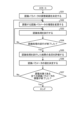
- 1 is a flowchart showing a procedure of a process executed by an object recognition device according to a first embodiment
- FIG. 13 is a diagram showing a functional configuration of an object recognition device according to a second embodiment
- 11 is a flowchart showing a procedure of a process executed by an object recognition device according to a second embodiment.
- FIG. 13 is a diagram for explaining an example of an image conversion method performed by an object recognition device according to a second embodiment.
- FIG. 13 is a diagram showing a functional configuration of an object recognition device according to a third embodiment.
- 11 is a flowchart showing a procedure of a process executed by an object recognition device according to a third embodiment.
- FIG. 13 is a diagram showing a configuration example of a simulation condition setting unit included in an object recognition device according to a third embodiment
- FIG. 13 is a diagram showing a configuration example of a data set generation unit included in an object recognition device according to a third embodiment.
- FIG. 13 is a diagram showing a functional configuration of a control device according to a fourth embodiment.
- FIG. 13 is a diagram showing a configuration example of a parameter adjustment unit included in a control device according to a fourth embodiment
- FIG. 13 is a diagram showing a configuration example of a grip parameter adjustment unit included in a control device according to a fourth embodiment
- 13 is a flowchart showing a procedure of a process executed by a grip parameter adjustment unit of a control device according to a fourth embodiment.
- FIG. 13 is a diagram showing a configuration example of a recognition parameter adjustment unit included in a control device according to a fourth embodiment; 13 is a flowchart showing a procedure of a process executed by a recognition parameter adjustment unit of the control device according to the fourth embodiment.
- FIG. 1 is a diagram showing a first example of a hardware configuration for realizing an object recognition device according to the first to fourth embodiments.
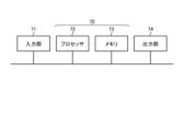
- FIG. 1 is a diagram showing a second example of a hardware configuration for realizing an object recognition device according to the first to fourth embodiments.
- Embodiment 1. 1 is a diagram showing a functional configuration of an object recognition device 10A according to a first embodiment.
- the object recognition device 10A recognizes an object from an image of the object.
- the object recognition device 10A includes an image acquisition unit 11, an image conversion unit 12, and a recognition unit 13.
- the object recognized by the object recognition device 10A may be an object to be grasped by an industrial robot.
- the industrial robot may grasp the object recognized by the object recognition device 10A from among a plurality of objects and pick the object.
- the industrial robot repeats this operation to pick the objects one by one.
- Each of the plurality of objects may have the same shape, or may have irregular shapes.
- each of the objects is referred to as a fixed-shaped object.
- each of the objects is referred to as an irregular-shaped object.
- An example of a fixed-shaped object is a part of an industrial product.
- An example of an irregular-shaped object is food that can be sorted into pieces.
- the object recognized by the object recognition device 10A is not limited to an object to be picked.
- the object recognition device 10A may recognize objects other than the object to be picked.
- the arrangement of the multiple objects is arbitrary.
- the multiple objects may be, for example, bulk stacked or aligned.
- Bulk stacking means that the objects are stacked in a random state with random positions and orientations.
- Aligning multiple objects means that each object is arranged in a predetermined position and with a predetermined orientation.
- the image acquisition unit 11 acquires an image of an object.
- the image conversion unit 12 converts the image of the object into a converted image in which the edges of the object are replaced with edges whose features are emphasized.
- the recognition unit 13 recognizes the object based on the converted image.
- the image conversion unit 12 converts an image of a photographed object into a converted image in which the edges of the object are replaced with edges that emphasize a feature common to the edges of the multiple objects. That is, in the converted image, the edges of the multiple objects are emphasized in which a common feature present in the edges of the multiple objects is emphasized. Note that the edges in the converted image may be edges in which the features of an edge of an object of a predetermined shape are emphasized. That is, the image conversion unit 12 may convert an image of a photographed object into a converted image in which the edges of the object are replaced with edges that emphasize a predetermined feature.
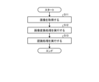
- FIG. 2 is a flowchart showing the process steps performed by the object recognition device 10A according to the first embodiment.
- step S11 the image acquisition unit 11 acquires an image of an object.
- the image acquisition unit 11 outputs the acquired image to the image conversion unit 12.
- step S12 the image conversion unit 12 executes an image conversion process, which is a process of converting the image input to the image conversion unit 12.
- the image conversion unit 12 converts the image into a converted image in which the edges of the objects are replaced with edges that emphasize features common to the edges of the multiple objects.
- the image conversion unit 12 outputs the converted image to the recognition unit 13.
- step S13 the recognition unit 13 executes a recognition process to recognize an object based on the converted image input to the recognition unit 13.
- the recognition unit 13 outputs the object recognition result to the outside of the object recognition device 10A.
- the object recognition device 10A ends the process according to the procedure shown in FIG. 2.
- the device that photographs the object is a two-dimensional (2D) camera or a three-dimensional (3D) sensor.
- the image acquisition unit 11 acquires, for example, an image captured by a general-purpose 2D camera or an image captured by a general-purpose 3D sensor.
- the image acquisition unit 11 acquires an image, for example, by inputting an image captured by a 2D camera or 3D sensor external to the image acquisition unit 11.
- the 2D camera or 3D sensor may be provided in the image acquisition unit 11. In this case, the image acquisition unit 11 acquires an image by the 2D camera or 3D sensor capturing the image.
- the image acquisition unit 11 acquires 2D data, which is data of a 2D image, by a 2D camera.
- the 2D image is, for example, a grayscale image or an RGB image, which is a color image.
- the image acquisition unit 11 acquires 3D data, which is data of a 3D image, by a 3D sensor.
- the 3D image is, for example, a three-dimensional point cloud or a distance image.
- the 2D camera may be simply referred to as a camera
- the 3D sensor may be simply referred to as a sensor.
- the image acquisition unit 11 may acquire an image captured by a single camera or a single sensor, or may acquire multiple images captured by multiple cameras or multiple sensors.
- the image acquisition unit 11 may acquire images captured by multiple cameras with the same measurement method or specifications, or multiple sensors with the same measurement method or specifications. Alternatively, the image acquisition unit 11 may acquire images captured by multiple cameras with different measurement methods or specifications, or multiple sensors with different measurement methods or specifications.
- An example of sensors with the same measurement method or specifications is when all the multiple sensors are sensors that perform measurements using a structured illumination method.
- An example of sensors with different measurement methods or specifications is when some of the multiple sensors are sensors that perform measurements using a structured illumination method, and the remaining multiple sensors are sensors that perform measurements using a ToF (Time of Flight) method.
- ToF Time of Flight
- the image input from the image acquisition unit 11 to the image conversion unit 12 is a single image or multiple images.
- the multiple images are, for example, images taken by multiple cameras with the same measurement method or specifications, or images taken by multiple sensors with the same measurement method or specifications.
- the multiple images may be images taken by multiple cameras with different measurement methods or specifications, or images taken by multiple sensors with different measurement methods or specifications.
- the image conversion unit 12 applies deformations to the edges of objects depicted in the image to emphasize their features. In this way, the image conversion unit 12 replaces the edges of the objects with edges whose features are emphasized.
- the image conversion unit 12 emphasizes the edge features by simplifying the edges of the objects depicted in the image more than the actual edges. It can also be said that the image conversion unit 12 simplifies the edges of the objects based on their features.
- the image conversion unit 12 replaces the edges of each object with edges whose features are emphasized, thereby reducing the individual differences in the edges of each object.
- the image conversion unit 12 converts the image into a converted image by replacing the edges of the objects with edges whose predetermined features are emphasized. For example, if random irregularities exist in each object, the irregularities contained in the edges are omitted, and the edges of each object are converted into smooth and simple edges.
- the image conversion unit 12 replaces the random shape of each object with a primitive shape, which is a simple shape such as a cylinder. In other words, the object depicted in the image is converted by the image conversion unit 12 into a figure that roughly represents the shape of the object.
- the image conversion unit 12 does not necessarily replace the edges of the multiple objects with edges of the same shape.
- the replaced edges for each of the multiple objects may include edges of different shapes.
- the edges may be of shapes with cylinders of different heights, or may be of shapes with cylinders of different radii.
- the image conversion unit 12 may also replace the edges of each object with edges of a shape other than a cylinder. If the objects are fixed shapes, the image conversion unit 12 may replace the edges of the objects with edges that are simplified from the actual edges.
- the image conversion unit 12 converts the image into a converted image by replacing the edges of the objects with edges that emphasize the features common to the edges of the objects.
- the image conversion unit 12 finds the features common to the edges of the objects by extracting information about the characteristic edges of the edges of the objects.
- the image conversion unit 12 converts the image into a converted image based on the features common to the edges of the objects.
- the image conversion unit 12 also replaces the random shape of each object with a primitive shape that is a simple shape such as a cylinder.
- the cylinder is a shape obtained by eliminating random elements in the edges of each object, and can be said to be a feature common to the edges of the objects.
- the replaced edges for each object may include edges of different shapes.
- the image conversion unit 12 may also replace the edges of each object with edges of a shape other than a cylinder.
- the image conversion unit 12 detects edges, for example, by performing image conversion processing on a distance image obtained by a sensor using a known method such as the Canny method.
- the image conversion unit 12 may determine in advance for each sensor a filter value that can make edges easier to detect, and detect edges based on the determined filter value.
- the image conversion unit 12 extracts characteristic edge information for each edge of multiple objects from the edges obtained in each image, and generates a converted image based on the extracted information. In this way, by extracting edge information from each image obtained by multiple sensors, the image conversion unit 12 can have edge information that could not be obtained from individual images be mutually complemented by the multiple images.
- the image conversion unit 12 may extract edge information from each of two types of images among a three-dimensional point cloud, a distance image, a grayscale image, and a color image. In this case, the image conversion unit 12 extracts characteristic edge information for each edge of a plurality of objects from the edges obtained in each of the two types of images, and generates a converted image based on the extracted information. In this case, too, the image conversion unit 12 can use the two types of images to mutually complement edge information that could not be obtained from individual images.
- a method utilizing machine learning may be applied to the image conversion by the image conversion unit 12.
- the image conversion unit 12 may convert an image of an object into a converted image based on the results of learning the image of the object and the converted image.
- a distance image obtained by a sensor and a distance image in which the edges of the object are emphasized may be input to a neural network, and learning may be performed to emphasize the edges of the distance image obtained by the sensor.
- algorithms such as GAN (Generative Adversarial Networks) or U-Net may be used.
- learning algorithms such as a support vector machine or random forest may be used to learn to estimate edges included in the distance image obtained by the sensor.
- the recognition unit 13 performs recognition processing on the converted image converted by the image conversion unit 12.
- the recognition unit 13 may calculate the position and orientation of the hand when the robot hand grasps an object, or the position and orientation of the object, through the recognition processing.
- the recognition unit 13 may calculate the position and orientation of the hand when grasping an object, or the position and orientation of the object, using a neural network.
- the recognition processing by the recognition unit 13 is not limited to the processing described in embodiment 1.
- the recognition processing by the recognition unit 13 may be processing other than the processing described in embodiment 1.
- the image conversion unit 12 converts the image into a converted image in which the edges of the object are replaced with edges whose features are emphasized.
- the recognition unit 13 recognizes the object based on the converted image.
- the object recognition device 10A generates a converted image in which the edges of the object are replaced with edges whose features are emphasized, thereby making it possible to individually separate and recognize an object from among a plurality of objects.
- the object recognition device 10A can obtain a converted image in which the individual differences in the edges of each object are reduced and which makes it easy to individually recognize the object, regardless of the type of sensor or the type of camera.
- the object recognition device 10A has the effect of improving the recognition accuracy of the object.
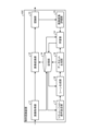
- FIG. 3 is a diagram showing a functional configuration of an object recognition device 10B according to the second embodiment.
- the same components as those in the first embodiment are given the same reference numerals, and the configuration different from the first embodiment will be mainly described.
- the object recognition device 10B recognizes an object from a captured image of the object.
- the object recognition device 10B has a configuration similar to that of the object recognition device 10A shown in FIG. 1. Furthermore, the object recognition device 10B has a learning unit 14, an image conversion evaluation unit 15, and a memory unit 16.
- the image conversion unit 12 performs machine learning to generate a converted image in which the edges of an object are replaced with edges whose features are emphasized.
- the image conversion unit 12 performs machine learning to generate a converted image in which the edges of an object are replaced with edges whose features common to the edges of multiple objects are emphasized.
- the image conversion unit 12 performs machine learning to generate a converted image in which the edges of an object are replaced with edges whose predetermined features are emphasized.
- the image conversion unit 12 learns image conversion parameters for converting a photographed image of an object into a converted image.
- the image conversion unit 12 stores the image conversion parameters, which are the learning results, in the memory unit 16.
- the image conversion unit 12 generates a converted image based on the image conversion parameters.
- the image conversion unit 12 stores the image conversion parameters in the memory unit 16.
- the image conversion evaluation unit 15 evaluates the performance of the image conversion using the image conversion parameters by the image conversion unit 12.
- the image conversion evaluation unit 15 determines through evaluation processing whether the image conversion executed by the image conversion unit 12 is an image conversion that allows objects to be individually separated and recognized.
- the learning unit 14 learns the image transformation parameters based on the results of the evaluation by the image transformation evaluation unit 15.
- the learning of the image transformation parameters by the learning unit 14 corresponds to the relearning of the image transformation parameters learned by the image transformation unit 12.
- the storage unit 16 stores image conversion parameters.
- the storage unit 16 also stores an image of an object, which is an image acquired by the image acquisition unit 11, and a target conversion image, which is an image to be converted by the image conversion unit 12.
- the target conversion image is an image in which the edges of the object are emphasized and noise is reduced.
- the target conversion image may be a CG (Computer Graphics) image in which the edges of the object are simplified based on features common to the edges of multiple objects.
- the target conversion image may be an image close to a CG image.
- the shape of the object may be approximated to a primitive shape, which is a simple shape such as a cylinder.
- the post-conversion image may be a CG image or an image close to a CG image.
- the target conversion image stored in the storage unit 16 is also used as learning data used for learning in the learning unit 14.
- Figure 4 is a flowchart showing the processing steps executed by the object recognition device 10B according to the second embodiment.
- step S21 the image acquisition unit 11 acquires an image of an object.
- the image acquisition unit 11 outputs the acquired image to the image conversion unit 12.
- the image acquisition unit 11 outputs the acquired image to the image conversion unit 12.
- the image acquisition unit 11 also stores the acquired image in the storage unit 16.
- step S22 the image conversion unit 12 executes an image conversion process, which is a process of converting the image input to the image conversion unit 12.
- the image conversion unit 12 learns image conversion parameters for obtaining a converted image from an image of an object.
- the image conversion unit 12 generates a converted image based on the image input to the image conversion unit 12 and the image conversion parameters that are the learning results.
- the image conversion unit 12 outputs the converted image to the recognition unit 13.
- step S23 the recognition unit 13 executes a recognition process to recognize an object based on the converted image input to the recognition unit 13.
- the recognition unit 13 outputs the object recognition result to the outside of the object recognition device 10B.
- the recognition unit 13 also outputs the object recognition result to the image conversion evaluation unit 15.
- step S24 the image conversion evaluation unit 15 performs an evaluation process of the image conversion performed in step S22 based on the result of object recognition by the recognition unit 13.
- the image conversion evaluation unit 15 determines by the evaluation process whether the image conversion performed in step S22 is an image conversion that allows objects to be individually separated and recognized. Specifically, the image conversion evaluation unit 15 evaluates the suitability of the image conversion parameters used in the image conversion process.
- step S22 If it is determined that the image transformation performed in step S22 is an image transformation that allows objects to be individually separated and recognized (step S25, Yes), the object recognition device 10B ends the processing according to the procedure shown in FIG. 4.
- step S22 determines that the image transformation performed in step S22 is not an image transformation that allows objects to be individually separated and recognized (step S25, No)
- the image transformation evaluation unit 15 outputs an evaluation result indicating that the image transformation is not an image transformation that allows objects to be individually separated and recognized to the learning unit 14.
- step S26 the learning unit 14 executes a learning process to learn image transformation parameters.
- the learning unit 14 reads the image transformation parameters from the storage unit 16, and learns the image transformation parameters based on the results of the evaluation by the image transformation evaluation unit 15.
- the learning unit 14 stores the image transformation parameters, which are the learning results, in the storage unit 16.
- the object recognition device 10B Upon completing step S26, the object recognition device 10B returns the procedure to step S21.
- the object recognition device 10B repeats the process according to the procedure from step S21 to step S25.
- the image conversion unit 12 converts a photographed image of an object into a converted image using a machine learning technique.
- a method using a GAN will be described as an example of an image conversion method that utilizes machine learning.
- FIG. 5 is a diagram for explaining an example of an image conversion method by the object recognition device 10B according to the second embodiment.
- FIG. 5 shows a conceptual diagram of an image conversion process using a GAN.
- the image acquired by the image acquisition unit 11 is assumed to be a distance image.
- the image conversion unit 12 acquires the distance image from the image acquisition unit 11.
- a clear image which is a distance image in which the edges of objects are emphasized and noise is reduced, is input to the image conversion unit 12.
- the clear image is stored, for example, in the memory unit 16.
- the image conversion unit 12 may acquire the clear image by reading it from the memory unit 16.
- the image conversion unit 12 inputs the distance image and the clear image to the generator G, causing the generator G to output a converted image. In this way, the image conversion unit 12 converts the acquired distance image into a converted image that has enhanced edges and reduced noise.
- the loss function of the generator G is expressed by the following formula (1).
- L G is the loss function of the generator G
- L is the labeling algorithm
- G is the generator G
- D is the classifier D
- x is the distance image acquired from the image acquisition unit 11
- x' is the clear image
- ⁇ is a weighting coefficient
- l is a logarithmic function
- ⁇ G is a parameter of the generator G
- ⁇ D is a parameter of the classifier D.
- the loss function shown in formula (1) uses a double error function of Least Square Generative Adversarial Networks (LSGAN).
- LSGAN Least Square Generative Adversarial Networks
- the labeling algorithm may be a known algorithm such as the Watershed algorithm.
- the clear image input to generator G may be a distance image captured by a sensor that is most likely to emphasize the edges of an object.
- the clear image input to generator G may be a pseudo image in which the edges of an object are emphasized and noise is reduced.
- a pseudo image is an image that is artificially created.
- the image conversion unit 12 obtains ⁇ G that minimizes L G , which is a loss function of the generator G. That is, the image conversion unit 12 obtains ⁇ G that satisfies the following formula (2).
- the image conversion unit 12 reads out the target transformed image from the storage unit 16.
- the image conversion unit 12 executes edge detection processing for each of the transformed image generated by the generator G and the target transformed image.
- the target transformed image is a CG image.
- an object is represented by a primitive shape.
- a known method such as a Laplacian filter or the Canny method may be used for the edge detection processing.
- the image conversion unit 12 inputs the converted image after edge detection and the CG image after edge detection to the classifier D.
- the image conversion unit 12 performs image conversion so that the smooth edges of the CG image are expressed in the converted image generated by the generator G.
- the loss function of the classifier D for performing image transformation so that the transformed image expresses smooth edges is expressed by the following formula (3):
- L D represents the loss function of the classifier D
- y represents a CG image.
- each of the multiple patches cut out from the distance image which is each of the converted image and the CG image
- a patch image an image in which an object is represented only by edges
- the image conversion unit 12 divides the classifier D into a local branch that performs classification for each patch image and a global branch that performs classification for the entire distance image, and classifies the converted image and the CG image. In this way, the image conversion unit 12 can prevent loss of information contained in the converted image, capture edge characteristics locally and globally, and perform learning to obtain a converted image that can express the smooth edges of the CG image.
- the image conversion unit 12 obtains ⁇ D that minimizes L D , which is a loss function of the classifier D. That is, the image conversion unit 12 obtains ⁇ D that satisfies the following formula (4).
- the network configuration, loss function, and parameters used in the machine learning are not limited to those described in the second embodiment, and may be changed as appropriate as necessary.
- the machine learning performed by the image conversion unit 12 is not limited to machine learning using a GAN, and may be machine learning using a neural network other than a GAN.
- the image conversion unit 12 learns, as image conversion parameters, ⁇ G, which is a parameter of the generator G, and ⁇ D, which is a parameter of the discriminator D, through the above-mentioned image conversion process using the GAN.
- the image conversion parameters learned by the image conversion unit 12 may be weight coefficients used in the loss function of the neural network, or weight coefficients set between units constituting the network.
- the image transformation evaluation unit 15 evaluates whether the image transformation performed by the image transformation unit 12 is an image transformation that allows objects to be individually separated and recognized. In other words, the image transformation evaluation unit 15 evaluates the validity of the image transformation from the perspective of object recognition.
- An image acquired by the image acquisition unit 11 and a labeling image in which correct labels are attached to objects included in the acquired image are prepared.
- a labeling process is executed on a converted image obtained by image conversion of the image acquired by the image acquisition unit 11 by the image conversion unit 12.
- the image conversion evaluation unit 15 finds the accuracy of individual separation by comparing the result of executing the labeling process on the converted image with the true value of the labeling image.
- the image conversion evaluation unit 15 evaluates the performance of the image conversion based on the accuracy of individual separation.
- the evaluation value when evaluating the performance of image conversion based on the accuracy of individual separation is expressed, for example, by the following formula (5).
- E is the evaluation value
- T is the true value of the labeling image
- R is the result of performing the labeling process on the converted image
- g(T) is the center of gravity of the correct answer region which is the region of the object in the labeling image
- g(R) is the center of gravity of the region of the object in the converted image.
- S(T) is the area of the correct answer region
- S(R) is the area of the region of the object in the converted image
- ⁇ is a weighting coefficient set for the center of gravity position
- ⁇ is a weighting coefficient set for the area of the region of the object
- N is the number of samples which is the number of objects included in the acquired image.
- the first term of the calculation formula following the summation symbol on the right side of formula (5) represents the evaluation value for the center of gravity position.
- the second term of the calculation formula following the summation symbol on the right side of formula (5) represents the evaluation value for the area of the region.
- the image conversion evaluation unit 15 evaluates the performance of the image conversion by comparing the calculated evaluation value with a preset threshold. In other words, the image conversion evaluation unit 15 evaluates the validity of the image conversion by comparing the evaluation value with the threshold. If the evaluation value calculated by formula (5) is less than the threshold, the image conversion evaluation unit 15 evaluates the performance of the image conversion as high. In other words, the image conversion evaluation unit 15 evaluates the image conversion performed by the image conversion unit 12 as an image conversion that allows objects to be individually separated and recognized.
- the image conversion evaluation unit 15 evaluates the performance of the image conversion as low. In other words, the image conversion evaluation unit 15 evaluates that the image conversion performed by the image conversion unit 12 is not an image conversion that allows objects to be individually separated and recognized. Note that the performance evaluation based on the evaluation value of the image conversion performance may be performed by a method other than the method of comparing the evaluation value with a threshold value.
- the method of evaluation by the image conversion evaluation unit 15 is not limited to the above method exemplified in the second embodiment, and may be any method.
- the learning unit 14 learns image transformation parameters. In this way, the learning unit 14 learns image transformation parameters based on the results of the evaluation by the image transformation evaluation unit 15.
- the learning unit 14 reads out from the storage unit 16 the image of the object, which is an image acquired by the image acquisition unit 11, and the target transformation image.
- the learning unit 14 learns image transformation parameters using the image of the object and the target transformation image.
- the learning unit 14 may learn image transformation parameters based on the image stored in the memory unit 16 and the target transformation image.
- the image conversion unit 12 converts the image acquired by the image acquisition unit 11 into a converted image based on the result of learning the image acquired by the image acquisition unit 11 and the converted image.
- the object recognition device 10B can obtain a converted image in which the individual differences of the edges of each object are reduced and the object can be easily recognized individually, regardless of the type of sensor or the type of camera.
- the object recognition device 10B can also obtain a converted image in which the object can be easily recognized individually, depending on the shape or size of the object to be recognized.
- the object recognition device 10B can obtain a converted image that enables easier individual recognition by learning image conversion parameters based on the result of evaluation by the image conversion evaluation unit 15.
- the object recognition device 10B has the effect of improving the recognition accuracy of the object.
- the recognition accuracy of the object can be improved, and the success rate of picking by the industrial robot can be improved.
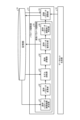
- FIG. 6 is a diagram showing a functional configuration of an object recognition device 10C according to the third embodiment.
- the same components as those in the first or second embodiment are denoted by the same reference numerals, and the configuration different from the first or second embodiment will be mainly described.
- the object recognition device 10C recognizes an object from an image of the object.
- the object recognition device 10C has a configuration similar to that of the object recognition device 10B shown in FIG. 3. Furthermore, the object recognition device 10C has a simulation condition setting unit 17, a scene generation unit 18, and a data set generation unit 19. Note that in the third embodiment, simulation refers to simulating a scene in which an object is photographed.
- the simulation condition setting unit 17 sets simulation conditions that are conditions for simulating photographing an object, and that include at least one of photographing device information, which is information about the device that photographs the image, and object information, which is information about the object.
- the photographing device information is information about the camera that photographs the image, or information about the sensor that photographs the image.
- the scene generation unit 18 simulates a scene in which an object is photographed, based on the simulation conditions set by the simulation condition setting unit 17.
- the dataset generation unit 19 generates a dataset to be used for learning, based on the scene generated by the scene generation unit 18.
- the dataset generated by the dataset generation unit 19 is learning data used for machine learning.
- the learning unit 14 learns image transformation parameters using the dataset generated by the dataset generation unit 19.
- a CAD (Computer-Aided Design) model of an object is stored in the memory unit 16.
- the CAD model stored in the memory unit 16 is at least one of a 3D CAD model and a 2D CAD model. If the object is amorphous, or if there is no 3D CAD model of the object, a model generated by a method such as mesh generation based on data obtained by measuring the object using a sensor or the like may be stored as the 3D CAD model. In the following description, the CAD model may be simply referred to as the model.
- FIG. 7 is a flowchart showing the process steps performed by the object recognition device 10C according to the third embodiment.
- step S31 the simulation condition setting unit 17 sets simulation conditions.
- the simulation condition setting unit 17 sets simulation conditions including at least one of imaging device information and object information.
- the simulation condition setting unit 17 reads out a model from the storage unit 16, and sets simulation conditions based on the model.
- the simulation condition setting unit 17 outputs information on the simulation conditions to the scene generation unit 18.
- step S34 the image acquisition unit 11 acquires an image of the object.
- the image acquisition unit 11 outputs the acquired image to the image conversion unit 12.
- the image acquisition unit 11 outputs the acquired image to the image conversion unit 12.
- the image acquisition unit 11 also stores the acquired image in the storage unit 16.
- step S35 the image conversion unit 12 executes an image conversion process, which is a process of converting the image input to the image conversion unit 12.
- the image conversion unit 12 learns image conversion parameters for obtaining a converted image from an image of an object.
- the image conversion unit 12 generates a converted image based on the image input to the image conversion unit 12 and the image conversion parameters that are the learning results.
- the image conversion unit 12 outputs the converted image to the recognition unit 13.
- step S36 the recognition unit 13 executes a recognition process to recognize an object based on the converted image input to the recognition unit 13.
- the recognition unit 13 outputs the object recognition result to the outside of the object recognition device 10C.
- the recognition unit 13 also outputs the object recognition result to the image conversion evaluation unit 15.
- step S37 the image conversion evaluation unit 15 performs an evaluation process of the image conversion executed in step S35 based on the result of object recognition by the recognition unit 13.
- the image conversion evaluation unit 15 determines by the evaluation process whether the image conversion executed in step S35 is an image conversion that allows objects to be individually separated and recognized. Specifically, the image conversion evaluation unit 15 evaluates the suitability of the image conversion parameters used in the image conversion process.
- step S35 If it is determined that the image transformation performed in step S35 is an image transformation that allows objects to be individually separated and recognized (step S38, Yes), the object recognition device 10C ends the processing according to the procedure shown in FIG. 7.
- step S38 determines that the image transformation performed in step S35 is not an image transformation that allows objects to be individually separated and recognized. If it is determined that the image transformation performed in step S35 is not an image transformation that allows objects to be individually separated and recognized (step S38, No), the image transformation evaluation unit 15 outputs an evaluation result indicating that the image transformation is not an image transformation that allows objects to be individually separated and recognized to the learning unit 14.
- step S39 the learning unit 14 executes a learning process to learn image transformation parameters.
- the learning unit 14 learns the image transformation parameters based on the data set input to the learning unit 14 and the results of the evaluation by the image transformation evaluation unit 15.
- the learning unit 14 stores the image transformation parameters, which are the learning results, in the storage unit 16.
- the object recognition device 10C Upon completing step S39, the object recognition device 10C returns the procedure to step S34.
- the object recognition device 10C repeats the process according to the procedure from step S34 to step S38.
- FIG. 8 is a diagram showing an example of the configuration of the simulation condition setting unit 17 of the object recognition device 10C according to the third embodiment.
- the simulation condition setting unit 17 includes a photographing device information setting unit 21, an object information setting unit 22, and an environmental information setting unit 23.
- the simulation condition setting unit 17 sets simulation conditions including photographing device information, object information, and environmental information.
- the imaging device information setting unit 21 sets imaging device information including at least one of information about the specifications of the device that captures the image and information about the installation of the device.
- Information about the device specifications includes parameters indicating the angle of view, working distance, installation angle, or resolution.
- Information about the installation of the device includes parameters indicating the position of the device in the simulation.
- the imaging device information setting unit 21 may read a model from the storage unit 16 and check that an object fits within the field of view of the device in the simulation.
- the object information setting unit 22 sets object information.
- the object information includes information about the color of the object or the size of the object.
- the object information setting unit 22 reads out a model from the storage unit 16 and sets the object information based on the model.
- the object information set by the object information setting unit 22 may also include information about the number of models used in the scene generated by the scene generation unit 18.
- the environmental information setting unit 23 sets environmental information.
- the environmental information includes information about the light source, such as information about diffuse reflection or ambient light.
- the environmental information may include information indicating the size of the box in which the objects are stacked in bulk, or information indicating the method by which the objects are supplied to the location from which they are picked up.
- the supply method refers to the state in which the objects are arranged, such as a bulk stacked state or an aligned state.
- the environmental information setting unit 23 may read a model from the storage unit 16 and confirm the supply method in a simulation based on the model.
- the simulation condition setting unit 17 outputs information on the simulation conditions, including the photographing equipment information, object information, and environmental information, to the scene generation unit 18.
- the simulation conditions set by the simulation condition setting unit 17 are not limited to including photographing equipment information, object information, and environmental information. It is sufficient that the simulation conditions include at least one of the photographing equipment information and the object information.
- the simulation condition setting unit 17 is not limited to including all of the photographing equipment information setting unit 21, the object information setting unit 22, and the environmental information setting unit 23. It is sufficient that the simulation condition setting unit 17 includes at least one of the photographing equipment information setting unit 21 and the object information setting unit 22.
- the scene generated by the scene generation unit 18 can be said to be the situation in which the object is photographed. For example, when objects are picked one by one from a pile of multiple objects, the scene is a situation in which the objects are arranged with random positions and orientations.
- the scene generation unit 18 reads a model from the memory unit 16 and simulates the scene using the simulation conditions and the model.
- the scene generation unit 18 may generate a scene using multiple models. If the object is an amorphous object, the multiple models used to generate the scene may include models of the same shape, or may include models of different shapes. For example, the scene generation unit 18 may use 50 models by reading 10 models of different shapes from the storage unit 16 and generating five copies of each model. In this way, by using models of different shapes to generate a scene, the object recognition device 10C is able to perform image conversion for each of multiple objects with irregular shapes.
- FIG. 9 is a diagram showing an example of the configuration of the data set generation unit 19 of the object recognition device 10C according to the third embodiment.
- the data set generation unit 19 includes a 2D data generation unit 24, a 3D data generation unit 25, an annotation data generation unit 26, and a target transformation image generation unit 27.
- the 2D data generation unit 24 and the 3D data generation unit 25 function as an image data generation unit that generates image data.
- the 2D data generation unit 24 generates 2D data, which is image data showing the scene generated by the scene generation unit 18.
- the 2D data generated by the 2D data generation unit 24 is image data such as a grayscale image or a color image.
- the 2D data generation unit 24 outputs the generated 2D data to the learning unit 14.
- the learning unit 14 may use the 2D data input to the learning unit 14 to learn image conversion parameters.
- the 3D data generation unit 25 generates 3D data, which is image data showing the scene generated by the scene generation unit 18.
- the 3D data generated by the 3D data generation unit 25 is image data such as a three-dimensional point cloud or a distance image.
- the 3D data generation unit 25 outputs the generated 3D data to the learning unit 14.
- the learning unit 14 may use the 3D data input to the learning unit 14 to learn image conversion parameters.
- the 2D data generation unit 24 may store the generated 2D data in the storage unit 16.
- the 3D data generation unit 25 may store the generated 3D data in the storage unit 16.
- the image conversion unit 12 may use the 2D data or 3D data, which is image data stored in the storage unit 16, for machine learning in the image conversion process.
- the image data generated by the image data generation unit may be at least one of 2D data representing the scene generated by the scene generation unit 18 and 3D data representing the scene generated by the scene generation unit 18.
- the data set generation unit 19 is not limited to having both the 2D data generation unit 24 and the 3D data generation unit 25.
- the data set generation unit 19 may be at least one of the 2D data generation unit 24 and the 3D data generation unit 25.
- the annotation data generation unit 26 generates annotation data to be added to the image data generated by the image data generation unit.
- the annotation data includes labeling data representing the color when an object is colored, information indicating the position and posture of the object, and type name information.
- an object is colored, for example, when multiple types of objects are included in multiple objects, the objects are color-coded according to their type.
- the type name is a name representing the type of object.
- the annotation data generation unit 26 outputs the generated annotation data to the learning unit 14.
- the learning unit 14 may use the annotation data input to the learning unit 14 to learn image conversion parameters.
- the target transformation image generating unit 27 generates a target transformation image, which is an image that is the target of image transformation from image data.
- the target transformation image is a grayscale image, a color image, or a distance image, and is an image in which the edges of an object are emphasized.
- the target transformation image may be a CG image in which the edges of an object are simplified based on features common to the edges of multiple objects.
- the target transformation image may be a CG image in which the edges of an object are replaced with edges in which predetermined features are emphasized.
- the target transformation image may be an image similar to these CG images.
- the shape of the object may be approximated to a primitive shape.
- the target transformation image generating unit 27 saves the generated target transformation image in the memory unit 16.
- the learning unit 14 may read the target transformation image generated by the target transformation image generation unit 27 from the storage unit 16, and learn image transformation parameters using the image data input to the learning unit 14 and the target transformation image.
- the image transformation unit 12 may read the image data generated by the image data generation unit and the target transformation image generated by the target transformation image generation unit 27 from the storage unit 16, and perform image transformation processing using the image data and the target transformation image.
- the dataset generated by the dataset generating unit 19 includes image data, annotation data, and a target transformed image.
- the dataset generated by the dataset generating unit 19 is not limited to one including image data, annotation data, and a target transformed image.
- the dataset generated by the dataset generating unit 19 does not have to include at least one of the image data, annotation data, and target transformed image.
- the data generated by the dataset generating unit 19 is data generated by simulation. For this reason, it is conceivable that there will be differences in the level of noise and the like between the image data generated by the dataset generating unit 19 and the image that is actually captured.
- the dataset generating unit 19 may be provided with a function for reproducing noise measured in advance in the image data generated by the dataset generating unit 19.
- the dataset generating unit 19 may reproduce the measured noise in accordance with the measurement method of the sensor, such as the structured illumination method or the ToF method.
- the image conversion unit 12 may input the distance image, which is the image data generated by the image data generation unit, and the CG image, which is the target transformation image generated by the target transformation image generation unit 27, to the neural network. In this way, the image conversion unit 12 may learn image transformation parameters such that the smooth edges of the CG image are represented in the transformed image.
- the image conversion evaluation unit 15 may calculate an evaluation value using annotation data, which is labeling data attached to a correct answer area, which is an area of an object in the image data generated by the image data generation unit.
- the evaluation value is an evaluation value when evaluating the performance of the image conversion based on the accuracy of individual separation.
- the image conversion unit 12 may learn image conversion parameters by reflecting the evaluation value in a loss function used for machine learning in the image conversion unit 12.
- the method of utilizing the data generated by the dataset generation unit 19 for learning is not limited to the method described in embodiment 3.
- the object recognition device 10C may appropriately increase the variety of methods of utilizing the data generated by the dataset generation unit 19 in addition to the method described in embodiment 3.
- the object recognition device 10C includes a simulation condition setting unit 17 that sets simulation conditions, a scene generation unit 18 that simulates a scene, and a dataset generation unit 19 that generates a dataset used for learning image transformation parameters.
- the object recognition device 10C can automatically collect learning data by simulating the actual environment in which an object is photographed.
- the object recognition device 10C can reduce the number of personnel and costs required to collect learning data, and can obtain learning data that enables highly accurate learning. As a result, the object recognition device 10C has the effect of enabling labor savings, cost reduction, and improved object recognition accuracy.
- the object recognition device 10C By using the object recognition device 10C to recognize objects during picking by an industrial robot, it is possible to reduce the number of workers at the site where the industrial robot is operated, shorten the time required for verification before the industrial robot is put into operation, and reduce the costs required for verification before operation. By simulating the actual environment in which the object is photographed using the object recognition device 10C, it is possible to improve the reproducibility of the simulation process before the introduction of the industrial robot. This makes it possible to accurately determine the placement of the industrial robot or check the operation of the industrial robot.
- Embodiment 4 an example will be described in which a control device including an object recognition device automatically adjusts picking-related parameters.
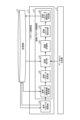
- Fig. 10 is a diagram showing the functional configuration of a control device 60 according to the fourth embodiment.
- the same components as those in the first to third embodiments are given the same reference numerals, and the configuration different from the first to third embodiments will be mainly described.
- an industrial robot will be simply referred to as a robot.
- the robot comprises a robot main body 62 and a control device 60 that controls the robot main body 62.
- Figure 10 shows the control device 60 and the robot main body 62.
- the control device 60 comprises an object recognition device 10D and a robot control unit 61.
- the object recognition device 10D recognizes an object from a photographed image of the object.
- the object recognition device 10D outputs the result of object recognition to the robot control unit 61.
- the robot control unit 61 controls the robot main body 62 based on the result of object recognition by the object recognition device 10D.
- the robot body 62 has a hand that grasps an object.
- the hand is not shown in the figure.
- the robot control unit 61 causes the robot body 62 to execute an operation to grasp an object based on the grasping position detected by the object recognition device 10D.
- the robot body 62 grasps the object and picks it up.
- the robot repeats such an operation to pick up objects one by one from a plurality of objects.
- the robot control unit 61 picks each of the multiple objects based on the results of object recognition by the object recognition device 10D.
- the method of determining the picking order for each of the multiple objects is not limited to that described in embodiment 4.
- the robot control unit 61 may pick each of the multiple objects stacked in the vertical direction in order from the object that is in the highest position.
- the picking order may be determined based on the likelihood and the position.
- the robot control unit 61 may pick each of the multiple objects in order from the object that has the highest likelihood and is in the highest position.
- the criteria for determining the picking order may be changed as necessary.
- the robot body 62 may be equipped with a force sensor, a proximity sensor, a tactile sensor, or the like. Multiple objects may be picked by a single robot, or multiple robots.
- the object recognition device 10D has a configuration similar to that of the object recognition device 10C shown in FIG. 6. Furthermore, the object recognition device 10D has a parameter adjustment unit 31 that adjusts parameters related to picking.
- the parameter adjustment unit 31 adjusts gripping parameters, which are parameters related to the hand used for picking.
- the parameter adjustment unit 31 also adjusts recognition parameters, which are parameters used in the recognition process during picking.
- the parameter adjustment unit 31 stores the adjusted gripping parameters and the adjusted recognition parameters in the storage unit 16.
- the object recognition device 10D automatically adjusts the picking-related parameters by simulation.
- FIG. 11 is a diagram showing an example of the configuration of the parameter adjustment unit 31 of the control device 60 according to the fourth embodiment.
- FIG. 11 shows the storage unit 16, the data set generation unit 19, and the parameter adjustment unit 31.
- the parameter adjustment unit 31 includes a gripping parameter adjustment unit 32 and a recognition parameter adjustment unit 33.
- the gripping parameter adjustment unit 32 adjusts gripping parameters, which are parameters for the hand of the robot body 62 that grips an object.
- the recognition parameter adjustment unit 33 adjusts recognition parameters, which are parameters used in object recognition by the recognition unit 13.
- the storage unit 16 stores a CAD model of the object.
- the grip parameter adjustment unit 32 reads the CAD model of the object from the storage unit 16 and adjusts the grip parameters using the CAD model of the object.
- the grip parameter adjustment unit 32 stores the adjusted grip parameters in the storage unit 16.
- the hands possessed by the robot body 62 may be tweezers hands, parallel hands, or suction pads.
- the gripping parameter adjustment unit 32 adjusts the gripping parameters for these various hands.
- the gripping parameters include parameters such as the hand opening width or hand claw width.
- the gripping parameter adjustment unit 32 adjusts the parameter values such as the hand opening width or claw width so that an object can be easily gripped.
- the type of hand used to grip an object may be determined by the user of the robot.
- the gripping parameters include multiple types of parameters for the hand, such as an opening width parameter or a claw width parameter.
- the gripping parameters refer to each of the multiple types of parameters.
- the multiple types of gripping parameters are also referred to as multiple gripping parameters.
- the gripping parameter adjustment unit 32 adjusts each of the multiple gripping parameters by determining the value of each of the multiple gripping parameters.
- the grip parameter adjustment unit 32 may adjust all of the multiple grip parameters simultaneously, or may adjust the multiple grip parameters individually in a predetermined order. In the following description, it is assumed that the grip parameter adjustment unit 32 adjusts the multiple grip parameters individually in a predetermined order.
- the recognition parameter adjustment unit 33 reads out the CAD model of the object and the grip parameters adjusted by the grip parameter adjustment unit 32 from the storage unit 16.
- the dataset generated by the dataset generation unit 19 is input to the recognition parameter adjustment unit 33.
- the recognition parameter adjustment unit 33 adjusts the recognition parameters using the CAD model, the grip parameters, and the dataset.
- the recognition parameter adjustment unit 33 saves the adjusted recognition parameters in the storage unit 16.
- the recognition parameter adjustment unit 33 adjusts, for example, recognition parameters, which are parameters for detecting grip position candidates or the position and orientation of each object from 2D data or 3D data.
- the recognition parameter adjustment unit 33 may adjust parameters of a learning model for detecting grip positions by machine learning.
- the recognition parameter adjustment unit 33 may adjust parameters of a learning model in machine learning used in auxiliary processing for improving the recognition rate.
- An example of auxiliary processing for improving the recognition rate is segmentation.
- the recognition parameter adjustment unit 33 mainly adjusts parameters for detecting grip position candidates from 2D data.
- the recognition parameters include multiple types of parameters used by the recognition unit 13 in recognizing an object.
- the recognition parameters refer to each of the multiple types of parameters.
- the multiple types of recognition parameters are also referred to as multiple recognition parameters.
- the recognition parameter adjustment unit 33 adjusts each of the multiple recognition parameters by determining the value of each of the multiple recognition parameters.
- the recognition parameter adjustment unit 33 may adjust all of the multiple recognition parameters simultaneously, or may adjust the multiple recognition parameters individually in a predetermined order. In the following description, it is assumed that the recognition parameter adjustment unit 33 adjusts the multiple recognition parameters individually in a predetermined order.
- FIG. 12 is a diagram showing an example of the configuration of the grasping parameter adjustment unit 32 of the control device 60 according to the fourth embodiment.
- FIG. 12 shows the storage unit 16, the data set generation unit 19, and the grasping parameter adjustment unit 32 and the recognition parameter adjustment unit 33 of the parameter adjustment unit 31.
- the grip parameter adjustment unit 32 includes a grip parameter adjustment range determination unit 41, a grip parameter change unit 42, a model rotation unit 43, a grip evaluation unit 44, a grip parameter value determination unit 45, and a grip parameter adjustment end determination unit 46.
- the grip parameter adjustment range determination unit 41 determines the adjustment range for each of the multiple grip parameters.
- the grip parameter adjustment range determination unit 41 determines the adjustment range based on a model stored in the storage unit 16, etc.
- the grip parameter adjustment unit 32 adjusts the value of each of the multiple grip parameters within the value range determined by the grip parameter adjustment range determination unit 41.
- the adjustment range of a grip parameter refers to a range within which the value of a grip parameter is adjusted.
- the grip parameter adjustment range determination unit 41 outputs information indicating the determined adjustment range to the grip parameter change unit 42.
- the grip parameter change unit 42 changes the grip parameter to be adjusted from among the multiple grip parameters.
- the grip parameter adjustment unit 32 adjusts each grip parameter by sequentially switching between the multiple grip parameters in the grip parameter change unit 42. In this way, the grip parameter adjustment unit 32 adjusts the multiple grip parameters individually in a predetermined order.
- the grip parameter change unit 42 outputs information indicating the grip parameter to be adjusted and information indicating the adjustment range of the grip parameter to be adjusted to the grip evaluation unit 44 via the model rotation unit 43.
- the model rotation unit 43 rotates the model of the object.
- the model rotation unit 43 reads the model stored in the storage unit 16 and executes a process to rotate the read model.
- the grip evaluation unit 44 evaluates whether the object will be grasped properly when grasped by the hand, assuming that the object will be made to assume the same posture as the model rotated by the model rotation unit 43. The grip evaluation unit 44 evaluates whether the object will be grasped properly when grasped by the hand, while adjusting the value of the grip parameter within the adjustment range, based on information indicating the grip parameter to be adjusted and information indicating the adjustment range of the grip parameter to be adjusted. The grip evaluation unit 44 outputs the result of the evaluation of whether the object will be grasped properly to the grip parameter value determination unit 45.
- the grip parameter value determination unit 45 determines the values of each of the multiple grip parameters based on the evaluation results by the grip evaluation unit 44. When the grip parameter value determination unit 45 determines the grip parameter value, it outputs the determined value to the grip parameter adjustment completion determination unit 46.
- the grip parameter adjustment completion determination unit 46 determines whether or not adjustment has been completed for all of the multiple grip parameters.
- the grip parameter adjustment completion determination unit 46 determines that adjustment has been completed for all of the multiple grip parameters by determining the grip parameter values for all of the multiple grip parameters.
- FIG. 13 is a flowchart showing the steps of the process executed by the grip parameter adjustment unit 32 of the control device 60 according to the fourth embodiment.
- the grip parameter adjustment range determination unit 41 determines the adjustment range of the grip parameters.
- the grip parameter adjustment range determination unit 41 reads out the model stored in the storage unit 16 and determines the adjustment range of the grip parameters based on the size of the model, etc.
- the grip parameter adjustment range determination unit 41 may also determine the initial value of the grip parameters based on the size of the model, etc.
- the initial value of the grip parameter is a value that is used as a reference when adjusting the value of the grip parameter.
- step S42 the grip parameter change unit 42 changes the type of grip parameter to be adjusted.
- the grip parameter change unit 42 changes the grip parameter to be adjusted from among the multiple grip parameters.
- step S43 the model rotation unit 43 rotates the model of the object.
- the model rotation unit 43 rotates the model randomly.
- the model rotation unit 43 may also rotate the model in a predetermined order.
- step S44 the grip evaluation unit 44 evaluates whether the grip is good or bad when the object is gripped by the hand.
- the grip evaluation unit 44 evaluates whether the grip is good or bad by assuming a situation in which the hand grips an object in the same posture as the model by fitting the hand model to the model rotated by the model rotation unit 43.
- the grip evaluation unit 44 evaluates whether the grip is good or bad by, for example, calculating an evaluation function of the grip parameters.
- the evaluation function of the grip parameters is composed of, for example, two evaluation values, the deviation occurrence frequency F Ang and the interference frequency F Col.
- the deviation occurrence frequency F Ang represents the frequency at which deviation occurs between the main axis of the object and the grip direction.
- the interference frequency F Col represents the frequency at which the object and the hand interfere with each other.
- step S45 determines the value of the grip parameter.
- the grip parameter value determination unit 45 determines the value of the grip parameter based on the result of the evaluation in step S44.
- the grip parameter value determination unit 45 for example, searches for the value of the grip parameter that minimizes the evaluation function of the grip parameter.
- the grip parameter value determination unit 45 determines the value of the grip parameter that minimizes the evaluation function of the grip parameter as the adjusted value of the grip parameter.
- the grip parameter adjustment completion determination unit 46 determines whether or not adjustment of all grip parameters to be adjusted in the grip parameter adjustment unit 32 has been completed. If adjustment of all grip parameters to be adjusted has not been completed (step S47, No), the grip parameter adjustment unit 32 returns the procedure to step S42. The grip parameter adjustment unit 32 executes the processes from step S42 to step S47 for the grip parameters for which adjustment has not been completed. On the other hand, if adjustment of all grip parameters to be adjusted has been completed (step S47, Yes), the grip parameter adjustment unit 32 ends the process according to the procedure shown in FIG. 13.
- FIG. 14 is a diagram showing an example of the configuration of the recognition parameter adjustment unit 33 of the control device 60 according to the fourth embodiment.
- FIG. 14 shows the storage unit 16, the data set generation unit 19, and the grip parameter adjustment unit 32 and the recognition parameter adjustment unit 33 of the parameter adjustment unit 31.
- the recognition parameter adjustment unit 33 includes a recognition parameter adjustment range determination unit 51, a recognition parameter change unit 52, a recognition trial unit 53, a recognition evaluation unit 54, a recognition parameter value determination unit 55, and a recognition parameter adjustment end determination unit 56.
- the recognition parameter adjustment range determination unit 51 determines the adjustment range for each of the multiple recognition parameters.
- the recognition parameter adjustment range determination unit 51 determines the adjustment range based on a model stored in the memory unit 16, etc.
- the recognition parameter adjustment unit 33 adjusts the value of each of the multiple recognition parameters within the value range determined by the recognition parameter adjustment range determination unit 51.
- the adjustment range of a recognition parameter refers to the range within which the value of the recognition parameter is adjusted.
- the recognition parameter adjustment range determination unit 51 outputs information indicating the determined adjustment range to the recognition parameter modification unit 52.
- the recognition parameter change unit 52 changes the recognition parameter to be adjusted from among the multiple recognition parameters.
- the recognition parameter adjustment unit 33 adjusts each recognition parameter by sequentially switching between the multiple recognition parameters in the recognition parameter change unit 52. In this way, the recognition parameter adjustment unit 33 adjusts the multiple recognition parameters individually in a predetermined order.
- the recognition parameter change unit 52 outputs information indicating the recognition parameter to be adjusted and information indicating the adjustment range of the recognition parameter to be adjusted to the recognition trial unit 53.
- the recognition trial unit 53 attempts recognition processing using the grip parameters adjusted by the grip parameter adjustment unit 32.
- the recognition trial unit 53 reads out the grip parameters adjusted by the grip parameter adjustment unit 32 from the storage unit 16.
- the recognition trial unit 53 acquires a dataset from the dataset generation unit 19.
- the recognition trial unit 53 detects candidates for grip positions by attempting recognition processing using the grip parameters on image data included in the dataset.
- the recognition trial unit 53 detects candidates for grip positions while adjusting the values of the recognition parameters within the adjustment range based on information indicating the recognition parameters to be adjusted and information indicating the adjustment range of the recognition parameters to be adjusted.
- the recognition trial unit 53 outputs the detection result of the candidates for grip positions, which is the result of the attempted recognition processing, to the recognition evaluation unit 54.
- the recognition evaluation unit 54 evaluates the quality of the results of the recognition process attempted by the recognition trial unit 53.
- the recognition evaluation unit 54 evaluates the quality of the results of the recognition process attempted, for example, by evaluating the suitability of the candidate grip positions detected by the recognition trial unit 53 as grip positions.
- the recognition evaluation unit 54 outputs the evaluation result of the quality of the results of the recognition process attempted to the recognition parameter value determination unit 55.
- the recognition parameter value determination unit 55 determines the values of each of the multiple recognition parameters based on the evaluation results by the recognition evaluation unit 54. When the recognition parameter value determination unit 55 determines the value of the recognition parameter, it outputs the determined value to the recognition parameter adjustment completion determination unit 56.
- the recognition parameter adjustment completion determination unit 56 determines whether or not adjustment has been completed for all of the multiple recognition parameters. The recognition parameter adjustment completion determination unit 56 determines that adjustment has been completed for all of the multiple recognition parameters when the recognition parameter values have been determined for all of the multiple recognition parameters.
- FIG. 15 is a flowchart showing the steps of the process executed by the recognition parameter adjustment unit 33 of the control device 60 according to the fourth embodiment.
- the recognition parameter adjustment range determination unit 51 determines the adjustment range of the recognition parameters.
- the recognition parameter adjustment range determination unit 51 reads out the model stored in the storage unit 16 and determines the adjustment range of the recognition parameters based on the size of the model, etc.
- the recognition parameter adjustment range determination unit 51 may also determine the initial value of the recognition parameters based on the size of the model, etc.
- the initial value of the recognition parameter is a value that is used as a reference when adjusting the value of the recognition parameter.
- step S52 the recognition parameter change unit 52 changes the type of recognition parameter to be adjusted. In other words, the recognition parameter change unit 52 changes the recognition parameter to be adjusted from among the multiple recognition parameters.
- step S53 the recognition trial unit 53 attempts recognition processing using the grip parameters adjusted by the grip parameter adjustment unit 32.
- the recognition trial unit 53 adjusts the values of the recognition parameters within the adjustment range, and detects candidates for the grip position for each value of the recognition parameter. If the recognition processing trials have not been completed for each value of the recognition parameter within the adjustment range (step S54, No), the recognition trial unit 53 returns the procedure to step S53 and continues adjusting the values of the recognition parameters and attempting the recognition processing.
- step S55 the recognition evaluation unit 54 evaluates the quality of the result of the trial of the recognition process in step S53.
- the recognition evaluation unit 54 evaluates the quality of the result of the trial of the recognition process, for example, by calculating an evaluation function of the recognition parameters.
- the evaluation function of the recognition parameters is composed of three evaluation values, for example, the amount of deviation E Pos between the candidate grip position detected in step S53 and the optimal grip position of the object, the amount of deviation E Ang between the main axis of the object and the grip direction, and the evaluation value E Num of the number of recognized objects.
- the number of recognized objects is the number of objects recognized by the object recognition device 10D.
- the evaluation value E Num of the number of recognized objects is an evaluation value regarding the number of recognized objects. In picking by a robot, it is required that the object to be picked is not left behind.
- the optimal grip position of an object is, for example, a position determined based on the center of gravity of the object.
- the optimal gripping position for an object may be a position arbitrarily determined by the user.
- the recognition parameter value determination unit 55 determines the value of the recognition parameter.
- the recognition parameter value determination unit 55 determines the value of the recognition parameter based on the result of the evaluation in step S54.
- the recognition parameter value determination unit 55 for example, searches for the value of the recognition parameter that minimizes the evaluation function of the recognition parameter.
- the recognition parameter value determination unit 55 determines the value of the recognition parameter that minimizes the evaluation function of the recognition parameter as the adjusted value of the recognition parameter.
- the recognition parameter adjustment completion determination unit 56 determines whether or not the adjustment of all recognition parameters to be adjusted in the recognition parameter adjustment unit 33 has been completed. If the adjustment of all recognition parameters to be adjusted has not been completed (step S57, No), the recognition parameter adjustment unit 33 returns the procedure to step S52. The recognition parameter adjustment unit 33 executes the processes from step S52 to step S57 for the recognition parameters for which adjustment has not been completed. On the other hand, if the adjustment of all recognition parameters to be adjusted has been completed (step S57, Yes), the recognition parameter adjustment unit 33 ends the process according to the procedure shown in FIG. 15.
- the recognition unit 13 shown in FIG. 10 may use the recognition parameters adjusted by the recognition parameter adjustment unit 33 when detecting candidates for gripping positions from a converted image obtained by converting an image of an object.
- the recognition unit 13 can read out the recognition parameters adjusted by the recognition parameter adjustment unit 33 from the storage unit 16, and detect candidates for gripping positions using the read out recognition parameters.
- the image conversion evaluation unit 15 shown in FIG. 10 may evaluate the performance of the image conversion using the image conversion parameters based on the operation results of the robot body 62.
- the image conversion evaluation unit 15 calculates an evaluation value for evaluating the performance of the image conversion based on the operation results when the robot body 62 is actually operated.
- the probability that the robot body 62 succeeds in grasping the object, the operation time during which the robot body 62 performs the operation of grasping the object, and the cause of the robot body 62 failing to grasp the object are observed.
- the image conversion evaluation unit 15 evaluates the performance of the image conversion based on the operation results including information on the probability that the robot body 62 succeeds in grasping the object, information on the operation time during which the robot body 62 performs the operation of grasping the object, and information indicating the cause of the robot body 62 failing to grasp the object.
- the image conversion evaluation unit 15 calculates an evaluation value for evaluating the performance of the image conversion, for example, by the following formula (6).
- E is an evaluation value for evaluating the performance of the image conversion
- P is a grasping success rate which is the probability of successfully grasping an object
- T is an action time during which the robot body 62 performs an action to grasp the object
- each of f1 , f2 , ... represents a cause of the robot body 62 failing to grasp the object.
- W1 is a weighting coefficient set for the grasping success rate
- W2 is a weighting coefficient set for the action time
- W31 , W32 , ... represent weighting coefficients set for each of f1 , f2 , ....
- the values of W31 , W32 , ... which are weighting coefficients set for the causes of grasping failure, may be set to small values for hardware-related causes such as a drop during transport, and to large values for causes related to the results of image conversion.
- the image conversion evaluation unit 15 may evaluate the performance of the image conversion, i.e., the validity of the image conversion, by comparing the evaluation value calculated as described above with a preset threshold value. If the evaluation value calculated by formula (6) is less than the threshold value, the image conversion evaluation unit 15 evaluates the performance of the image conversion as being high. In other words, the image conversion evaluation unit 15 evaluates the image conversion performed by the image conversion unit 12 as being an image conversion that allows objects to be individually separated and recognized.
- the image conversion evaluation unit 15 evaluates the performance of the image conversion as low. In other words, the image conversion evaluation unit 15 evaluates that the image conversion performed by the image conversion unit 12 is not an image conversion that allows objects to be individually separated and recognized. Note that the performance evaluation based on the evaluation value of the image conversion performance may be performed by a method other than the method of comparing the evaluation value with a threshold value.
- the method of evaluation by the image conversion evaluation unit 15 is not limited to the above method exemplified in embodiment 4, and may be any method.
- the learning unit 14 may learn image transformation parameters.
- the learning unit 14 learns the image transformation parameters using the image data stored in the memory unit 16 and the dataset generated by the dataset generation unit 19. In this way, the learning unit 14 learns the image transformation parameters based on the results of the evaluation by the image transformation evaluation unit 15.
- the control device 60 includes a gripping parameter adjustment unit 32 that adjusts gripping parameters, which are parameters for the hand that grips the object, and a recognition parameter adjustment unit 33 that adjusts recognition parameters, which are parameters used in object recognition by the recognition unit 13.
- the control device 60 can automatically adjust the gripping parameters and recognition parameters by simulating the actual environment in which the object is photographed.
- the control device 60 can reduce the number of personnel and costs required to adjust the gripping parameters or recognition parameters, and can improve the success rate of picking by the robot. As a result, the control device 60 has the effect of enabling labor savings, cost reduction, and an improvement in the success rate of picking.
- the control device 60 is equipped with an image conversion evaluation unit 15 that evaluates the performance of image conversion using the image conversion parameters based on the operation results of the robot main body 62.
- the control device 60 can check the validity of the image conversion parameters based on operation results such as the probability of successfully grasping an object, the operation time taken to grasp an object, or the cause of failure to grasp an object. This allows the control device 60 to obtain a converted image in which objects are easily separated and recognized individually, further improving the success rate of picking.
- control device 60 By using the control device 60 to control the industrial robot, it is possible to reduce the number of people required at the site where the industrial robot is operated, shorten the time required for verification before the industrial robot is put into operation, and reduce the costs required for verification before the robot is put into operation.
- control device 60 is described as being equipped with the object recognition device 10D, but is not limited to this.
- the control device 60 may also be equipped with the object recognition device 10A shown in FIG. 1, the object recognition device 10B shown in FIG. 3, or the object recognition device 10C shown in FIG. 6.
- the processing units of each of the object recognition devices 10A, 10B, 10C, and 10D are realized by a processing circuit.
- the processing unit of the object recognition device 10A includes the image acquisition unit 11, the image conversion unit 12, and the recognition unit 13 shown in FIG. 1.
- the processing unit of the object recognition device 10B includes the image acquisition unit 11, the image conversion unit 12, the recognition unit 13, the learning unit 14, and the image conversion evaluation unit 15 shown in FIG. 3.
- the processing unit of the object recognition device 10C includes the image acquisition unit 11, the image conversion unit 12, the recognition unit 13, the learning unit 14, the image conversion evaluation unit 15, the simulation condition setting unit, the scene generation unit 18, and the data set generation unit 19 shown in FIG. 6.
- the processing units of the object recognition device 10D include an image acquisition unit 11, an image conversion unit 12, a recognition unit 13, a learning unit 14, an image conversion evaluation unit 15, a simulation condition setting unit 17, a scene generation unit 18, a data set generation unit 19, and a parameter adjustment unit 31, all of which are shown in FIG. 10.
- the processing circuitry may be a circuit in which a processor executes software, or may be a dedicated circuit.
- the input unit 71 is an interface circuit that receives data transmitted from outside the object recognition devices 10A, 10B, 10C, 10D to the object recognition devices 10A, 10B, 10C, 10D and provides the data to the processor 72.
- the output unit 74 is an interface circuit that outputs data from the processor 72 or memory 73 to outside the object recognition devices 10A, 10B, 10C, 10D.
- the processing units of each of the object recognition devices 10A, 10B, 10C, and 10D are realized by software, firmware, or a combination of software and firmware.
- the software or firmware is written as a program and stored in the memory 73.
- the processor 72 reads and executes the program stored in the memory 73 to realize each function of the processing unit. That is, the processing circuit 70 has a memory 73 for storing a program that results in the processing of each function of the processing unit.
- This program can be said to be a program that causes a computer to execute the procedures and methods of the object recognition devices 10A, 10B, 10C, and 10D.
- the memory 73 is also used as a temporary memory when the processor 72 executes various processes.
- the storage unit 16 of the object recognition devices 10B, 10C, and 10D is realized by the memory 73.
- the processor 72 includes, for example, one or more of a CPU (Central Processing Unit), a DSP (Digital Signal Processor), and a system LSI (Large Scale Integration).
- the memory 73 includes one or more of a RAM (Random Access Memory), a ROM (Read Only Memory), a flash memory, an EPROM (Erasable Programmable Read Only Memory), and an EEPROM (registered trademark) (Electrically Erasable Programmable Read Only Memory).
- the memory 73 also includes a recording medium on which a computer-readable program is recorded. Such a recording medium includes one or more of a non-volatile or volatile semiconductor memory, a magnetic disk, a flexible memory, an optical disk, a compact disk, and a DVD (Digital Versatile Disc).
- FIG. 16 shows an example of hardware that realizes the processing unit using a general-purpose processor 72 and memory 73, but the processing unit may also be realized by a dedicated hardware circuit.
- FIG. 17 shows a second example of a hardware configuration that realizes the object recognition devices 10A, 10B, 10C, and 10D according to the first to fourth embodiments.
- the object recognition devices 10A, 10B, 10C, and 10D include a processing circuit 75, which is a dedicated hardware circuit, an input unit 71, and an output unit 74.
- the processing circuit 75 is a single circuit, a composite circuit, a programmed processor, a parallel programmed processor, an integrated circuit such as an ASIC (Application Specific Integrated Circuit) or an FPGA (Field Programmable Gate Array), or a circuit that combines these.
- Each function of the processing unit may be realized by the processing circuit 75 separately, or each function may be realized collectively by the processing circuit 75.
- Each function of the processing unit may be realized by a combination of the processing circuit 70 and the processing circuit 75.
- the control device 60 is realized by a hardware configuration similar to the hardware configuration illustrated in FIG. 16 or the hardware configuration illustrated in FIG. 17.
- the processing unit of the object recognition device 10D and the robot control unit 61 are realized by the processing circuit 70 or the processing circuit 75.
- the output unit 74 transmits data to the robot main body 62.
- 10A, 10B, 10C, 10D Object recognition device 11 Image acquisition unit, 12 Image conversion unit, 13 Recognition unit, 14 Learning unit, 15 Image conversion evaluation unit, 16 Memory unit, 17 Simulation condition setting unit, 18 Scene generation unit, 19 Data set generation unit, 21 Fishing device information setting unit, 22 Object information setting unit, 23 Environmental information setting unit, 24 2D data generation unit, 25 3D data generation unit, 26 Annotation data generation unit, 27 Target conversion image generation unit, 31 Parameter adjustment unit, 32 Grasping parameter adjustment unit, 33 Recognition parameters Adjustment unit, 41, grip parameter adjustment range determination unit, 42, grip parameter change unit, 43, model rotation unit, 44, grip evaluation unit, 45, grip parameter value determination unit, 46, grip parameter adjustment end determination unit, 51, recognition parameter adjustment range determination unit, 52, recognition parameter change unit, 53, recognition trial unit, 54, recognition evaluation unit, 55, recognition parameter value determination unit, 56, recognition parameter adjustment end determination unit, 60, control device, 61, robot control unit, 62, robot body, 70, 75, processing circuit, 71, input unit, 72
Landscapes
- Engineering & Computer Science (AREA)
- Physics & Mathematics (AREA)
- General Physics & Mathematics (AREA)
- Theoretical Computer Science (AREA)
- Multimedia (AREA)
- Computer Vision & Pattern Recognition (AREA)
- Image Analysis (AREA)
Priority Applications (2)
| Application Number | Priority Date | Filing Date | Title |
|---|---|---|---|
| PCT/JP2023/028151 WO2025027797A1 (ja) | 2023-08-01 | 2023-08-01 | 物体認識装置、制御装置、および物体認識方法 |
| JP2024550894A JPWO2025027797A1 (https=) | 2023-08-01 | 2023-08-01 |
Applications Claiming Priority (1)
| Application Number | Priority Date | Filing Date | Title |
|---|---|---|---|
| PCT/JP2023/028151 WO2025027797A1 (ja) | 2023-08-01 | 2023-08-01 | 物体認識装置、制御装置、および物体認識方法 |
Publications (1)
| Publication Number | Publication Date |
|---|---|
| WO2025027797A1 true WO2025027797A1 (ja) | 2025-02-06 |
Family
ID=94394858
Family Applications (1)
| Application Number | Title | Priority Date | Filing Date |
|---|---|---|---|
| PCT/JP2023/028151 Pending WO2025027797A1 (ja) | 2023-08-01 | 2023-08-01 | 物体認識装置、制御装置、および物体認識方法 |
Country Status (2)
| Country | Link |
|---|---|
| JP (1) | JPWO2025027797A1 (https=) |
| WO (1) | WO2025027797A1 (https=) |
Citations (5)
| Publication number | Priority date | Publication date | Assignee | Title |
|---|---|---|---|---|
| JP2020087155A (ja) * | 2018-11-29 | 2020-06-04 | キヤノン株式会社 | 情報処理装置、情報処理方法及びプログラム |
| WO2021149251A1 (ja) * | 2020-01-24 | 2021-07-29 | 三菱電機株式会社 | 物体認識装置および物体認識方法 |
| JP2021114048A (ja) * | 2020-01-16 | 2021-08-05 | 本田技研工業株式会社 | 情報処理装置、車両、車両の制御方法、プログラム、情報処理サーバ、情報処理方法 |
| JP2021120840A (ja) * | 2020-01-31 | 2021-08-19 | Kddi株式会社 | 学習方法、装置及びプログラム |
| JP7162760B2 (ja) * | 2019-12-10 | 2022-10-28 | 三菱電機株式会社 | モデル生成装置およびピッキングロボット |
-
2023
- 2023-08-01 JP JP2024550894A patent/JPWO2025027797A1/ja active Pending
- 2023-08-01 WO PCT/JP2023/028151 patent/WO2025027797A1/ja active Pending
Patent Citations (5)
| Publication number | Priority date | Publication date | Assignee | Title |
|---|---|---|---|---|
| JP2020087155A (ja) * | 2018-11-29 | 2020-06-04 | キヤノン株式会社 | 情報処理装置、情報処理方法及びプログラム |
| JP7162760B2 (ja) * | 2019-12-10 | 2022-10-28 | 三菱電機株式会社 | モデル生成装置およびピッキングロボット |
| JP2021114048A (ja) * | 2020-01-16 | 2021-08-05 | 本田技研工業株式会社 | 情報処理装置、車両、車両の制御方法、プログラム、情報処理サーバ、情報処理方法 |
| WO2021149251A1 (ja) * | 2020-01-24 | 2021-07-29 | 三菱電機株式会社 | 物体認識装置および物体認識方法 |
| JP2021120840A (ja) * | 2020-01-31 | 2021-08-19 | Kddi株式会社 | 学習方法、装置及びプログラム |
Also Published As
| Publication number | Publication date |
|---|---|
| JPWO2025027797A1 (https=) | 2025-02-06 |
Similar Documents
| Publication | Publication Date | Title |
|---|---|---|
| CN110609037B (zh) | 产品缺陷检测系统及方法 | |
| JP6573354B2 (ja) | 画像処理装置、画像処理方法、及びプログラム | |
| JP5812599B2 (ja) | 情報処理方法及びその装置 | |
| JP6004809B2 (ja) | 位置姿勢推定装置、情報処理装置、情報処理方法 | |
| JP5458885B2 (ja) | 物体検出方法と物体検出装置およびロボットシステム | |
| CN109102547A (zh) | 基于物体识别深度学习模型的机器人抓取位姿估计方法 | |
| JP6912215B2 (ja) | 対象物の姿勢等を検出する検出方法、検出プログラム | |
| WO2000057129A1 (en) | Three-dimensional object recognition method and pin picking system using the method | |
| CN115471542A (zh) | 一种基于YOLO v5的包装物双目识别定位方法 | |
| CN109934230A (zh) | 一种基于视觉辅助的雷达点云分割方法 | |
| CN114548253A (zh) | 一种基于图像识别及动态匹配的数字孪生模型构建系统 | |
| US11436754B2 (en) | Position posture identification device, position posture identification method and position posture identification program | |
| CN115131619B (zh) | 基于点云和图像融合的特高压零件分拣方法和系统 | |
| WO2020152927A1 (ja) | 学習用データ生成方法、学習用データ生成装置、および、推論処理方法 | |
| CN116587280A (zh) | 一种机器人3d激光视觉无序抓取控制方法、介质及系统 | |
| CN116984269B (zh) | 一种基于图像识别的煤矸石抓取方法及系统 | |
| CN116703895B (zh) | 基于生成对抗网络的小样本3d视觉检测方法及其系统 | |
| JP2020021212A (ja) | 情報処理装置、情報処理方法及びプログラム | |
| JP2022172461A (ja) | 物体検出を実施するための方法および計算システム | |
| JP5704909B2 (ja) | 注目領域検出方法、注目領域検出装置、及びプログラム | |
| CN116385793A (zh) | 基于双目视觉的快递分拣中堆垛纸箱识别与定位方法 | |
| WO2025027797A1 (ja) | 物体認識装置、制御装置、および物体認識方法 | |
| CN120516715A (zh) | 一种基于深度学习的五指灵巧手臂手位姿估计抓取方法 | |
| CN114241131A (zh) | 机器人抓取数据集的构建方法及其构建装置和存储介质 | |
| JP7066671B2 (ja) | 干渉判定装置、干渉判定方法、プログラム及びシステム |
Legal Events
| Date | Code | Title | Description |
|---|---|---|---|
| WWE | Wipo information: entry into national phase |
Ref document number: 2024550894 Country of ref document: JP |
|
| 121 | Ep: the epo has been informed by wipo that ep was designated in this application |
Ref document number: 23947594 Country of ref document: EP Kind code of ref document: A1 |
|
| NENP | Non-entry into the national phase |
Ref country code: DE |