WO2025027791A1 - 管制支援装置 - Google Patents
管制支援装置 Download PDFInfo
- Publication number
- WO2025027791A1 WO2025027791A1 PCT/JP2023/028130 JP2023028130W WO2025027791A1 WO 2025027791 A1 WO2025027791 A1 WO 2025027791A1 JP 2023028130 W JP2023028130 W JP 2023028130W WO 2025027791 A1 WO2025027791 A1 WO 2025027791A1
- Authority
- WO
- WIPO (PCT)
- Prior art keywords
- flight time
- trajectory
- aircraft
- flight
- data
- Prior art date
- Legal status (The legal status is an assumption and is not a legal conclusion. Google has not performed a legal analysis and makes no representation as to the accuracy of the status listed.)
- Pending
Links
Images








Classifications
-
- G—PHYSICS
- G08—SIGNALLING
- G08G—TRAFFIC CONTROL SYSTEMS
- G08G5/00—Traffic control systems for aircraft
Definitions
- This disclosure relates to a control support device, and in particular to a control support device that improves the accuracy of predicting aircraft flight times.
- Patent Document 1 discloses a technology that derives the mass of an aircraft from data extracted from aircraft flight parameters from a flight model and from operational data obtained by a device that accepts operational data, and predicts flight time based on this mass and flight parameters. It also discloses a technology that derives flight distance from the flight path, and derives flight time based on the flight distance and true ground speed.
- Patent Document 2 also discloses a technology that uses a neural network to input accumulated aircraft position information as learning data to build a prediction model with a learning function for predicting the future position of an aircraft, and predicts the future position (predicted position) of an aircraft by combining the acquired aircraft position information with the prediction model. If the predicted position and the actual acquired position deviate by more than a threshold, an alarm is issued. It also discloses a technology that performs route prediction using the acquired position and the prediction model, and predicts the future position based on that. If the predicted position and the observed value deviate by more than a threshold, an alarm is issued.
- Patent Document 1 derives an aircraft's flight time based on information on wind direction and speed and the mass of the aircraft, but aircraft also change their flight route depending on weather conditions, airspace congestion, and other factors, which can change the flight time. As these factors are not taken into account, it is believed that accurate prediction of flight time is difficult.
- Patent Document 2 discloses that the prediction model is changed to determine the prediction range taking into account weather, time fluctuations, day of the week fluctuations, and seasonal fluctuations. However, there is no detailed disclosure of when the model is switched, and it is thought that it would be difficult to accurately predict flight time from the predicted position.
- This disclosure has been made to solve the problems described above, and aims to provide a control support device that can predict aircraft flight times with high accuracy.
- the air traffic control support device includes a variation factor extraction unit that extracts data on variation factors of the flight time of the aircraft to a predetermined point from input flight data on the flight of the aircraft and meteorological data on weather, a feature extraction unit that extracts multiple feature amounts for predicting the flight time to the predetermined point from the data on the variation factors of the flight time, a database that stores the multiple extracted feature amounts, a flight time prediction model that predicts the flight time by machine learning using the multiple feature amounts, a flight time prediction unit that predicts the flight time using the flight time prediction model, and a trajectory prediction unit that predicts the trajectory of the aircraft using the flight time prediction result, where the variation factor extraction unit statistically extracts factors that may affect the variation of the flight time of the aircraft from the past flight data and meteorological data by machine learning, and sets the data on the variation factors of the flight time, and the trajectory prediction unit selects a representative trajectory from multiple track data accumulated in the past based on the prediction result of the flight time, and outputs it as the predicted trajectory of the aircraft.
- multiple feature quantities are extracted from data on factors that cause flight time fluctuations in order to predict flight time to a predetermined point, and a flight time prediction model is constructed by machine learning using the multiple feature quantities in the trajectory prediction unit, and flight time is predicted using the flight time prediction model, making it possible to predict aircraft flight time with high accuracy.
- predictions can be made that take into account the control habits of air traffic controllers, such as detouring when it is congested and taking shortcuts when it is clear.
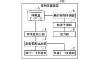
- FIG. 1 is a functional block diagram showing a configuration of a control assistance device according to a first embodiment.
- 4 is a flowchart illustrating an operation during learning of the air traffic control assistance device of the first embodiment.
- 4 is a flowchart illustrating an operation during prediction of the air traffic control assistance device of the first embodiment.
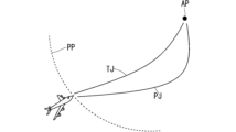
- FIG. 1 is a diagram illustrating a concept of trajectory prediction.
- FIG. 13 is a diagram illustrating the concept of a modified example of trajectory prediction.
- FIG. 13 is a diagram showing feature amounts extracted from continuous position information of multiple aircraft.
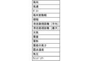
- FIG. 1 is a diagram showing feature amounts extracted from meteorological data observed for each airport.
- FIG. 1 is a diagram showing feature amounts extracted from radar information from the Japan Meteorological Agency.
- FIG. 13 is a diagram showing feature amounts extracted from information assigned to aircraft.
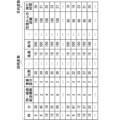
- FIG. 13 is a diagram illustrating data stored in a feature database.
- FIG. 13 is a diagram showing an example of extracting a histogram according to the magnitude of values for each divided area.
- FIG. 13 is a diagram illustrating a case where a waypoint is not passed due to trajectory variation.
- FIG. 10 is a diagram illustrating a process of predicting flight time using the created prediction model.
- FIG. 2 is a diagram illustrating a schematic diagram of a trajectory prediction by a trajectory prediction unit.
- FIG. 11 is a functional block diagram showing the configuration of a control assistance device according to a second embodiment.
- 13 is a diagram showing a schematic diagram of a process for predicting a trajectory and a flight time in the air traffic control assistance device of the second embodiment.
- FIG. 10 is a flowchart illustrating an operation during learning of the air traffic control assistance device of the second embodiment.
- 13 is a flowchart illustrating an operation during prediction of the air traffic control assistance device of the second embodiment.
- 13 is a diagram showing a schematic diagram of trajectory prediction and flight time prediction in the air traffic control assistance device of embodiment 2.
- FIG. FIG. 11 is a functional block diagram showing the configuration of a control assistance device according to a third embodiment.
- 13 is a flowchart illustrating an operation during learning of the air traffic control assistance device of the third embodiment.
- 13 is a flowchart illustrating the operation during prediction of the air traffic control assistance device of the third embodiment.
- FIG. 2 is a diagram illustrating a hardware configuration for implementing the air traffic control assistance device according to the first to third embodiments of the present disclosure.
- FIG. 2 is a diagram illustrating a hardware configuration for implementing the air traffic control assistance device according to the first to third embodiments of the present disclosure.
- the air traffic control support device is a device that supports air traffic control by predicting the trajectory and flight time of the aircraft to a predetermined point such as an airport and providing the information to the controller.
- FIG. 1 is a functional block diagram showing the configuration of an air traffic control assistance device 100 according to the first embodiment.
- the air traffic control assistance device 100 has a flight data receiving unit 1 that receives various flight data related to aircraft flight, and a weather data receiving unit 2 that receives various weather data related to weather.
- the flight data and weather data are input to a variation factor extraction unit 3 that extracts data related to the variation factors of flight time, and the variation factors of flight time are extracted.
- the extracted flight time variation factors are input to a feature extraction unit 4 that extracts features for constructing a flight time prediction model that predicts flight time, and the extracted features are stored in a feature database 5.
- the features stored in the feature database 5 are used by the flight time prediction unit 6 to construct and predict a flight time prediction model using machine learning, and the flight time until the aircraft lands at the airport or to a specified waypoint, a point where air traffic control instructions are likely to occur, a point where the wind direction changes, and a waypoint which is a waypoint on the standard route are predicted.
- Standard routes include STAR (Standard Instrument Arrival Route) and SID (Standard Instrument Departure), and there are multiple standard routes for each airport.
- the flight time prediction results are input to the trajectory prediction unit 7 and used to predict the trajectory of the aircraft.
- the trajectory prediction unit 7 selects and outputs a representative trajectory from the track data accumulated in the past based on the flight time prediction results and other feature quantities.
- the predicted aircraft flight time and trajectory are output to an air traffic control system and display via output unit 8 and are used for air traffic control.
- Figure 2 is a flowchart explaining the operation during learning using artificial intelligence (AI) in the air traffic control assistance device 100
- Figure 3 is a flowchart explaining the operation during prediction for predicting flight time using a prediction model created during learning.
- AI artificial intelligence
- the variation factor extraction unit 3 extracts data related to the variation factors of flight time from the flight data received by the flight data receiving unit 1 and the weather data received by the weather data receiving unit 2 (step S1).
- the variation factor extraction unit 3 uses AI and machine learning technology to statistically extract factors that are thought to have the greatest influence on variations in aircraft flight time from a large amount of past data. For example, aircraft change their flight pattern depending on weather conditions such as wind direction and strength, or the number of aircraft flying on the same route, i.e., congestion, which are thought to be factors that cause variations in required time and flight route. However, it is difficult to detect all individual factors and their effects and obtain a mathematical formula (model) that predicts flight route and flight time from the factors, so the variation factors are extracted using a statistical approach to big data processing using AI.
- the feature extraction unit 4 extracts features from the multiple variable factors extracted by the variable factor extraction unit 3 (step S2).
- the feature refers to the part of the weather data and flight data of the surrounding aircraft acquired by the flight data receiving unit 1 and the weather data receiving unit 2, which is useful for flight time and route prediction.
- Weather data and flight data of the surrounding aircraft are collected as a wide range of data, but the part that is actually useful for predicting the flight time and flight route of the aircraft is limited.
- the useful part i.e., the feature varies depending on the position of the aircraft at the time of starting the prediction, and a process is performed to extract the part to be used for prediction from the acquired data.
- the variable factor is weather data
- the weather data from the prediction start position to the airport is useful among the acquired weather data, and the weather data before the prediction start position is not necessary
- the process of extracting the weather data from the prediction start position to the airport is the process of extracting the feature
- the processing circuit that performs the extraction process by program is called the feature extraction unit 4.
- the features to be extracted include flight data of aircraft on the same standard route or other merging routes.
- the features extracted by the feature extraction unit 4 are stored in the feature database 5 (step S3).
- the feature database 5 stores a large number of feature quantities (explanatory variables) and their corresponding flight times (objective variables), and the flight time prediction unit 6 learns by linking the explanatory variables and the objective variables through regression analysis using supervised learning, and statistically processes these past data to create a prediction model that obtains the objective variable, flight time, from the explanatory variables. That is, as explained in the variation factor extraction unit 3, a flight time prediction model is constructed from a large amount of past data using machine learning technology using AI (step S4).
- the trajectory prediction unit 7 selects a representative trajectory corresponding to the past flight time and approach position (step S5).
- the approach position refers to the position when the aircraft arrives within 50 nautical miles (NM) of the airport when predicting the flight time and trajectory from 50 nautical miles (NM) from the airport to landing, for example, and a representative trajectory is selected from multiple trajectories that the aircraft has taken in the past from the approach position to the airport, and prepared for prediction.
- the variation factor extraction unit 3 extracts data related to the variation factors of flight time from the flight data received by the flight data receiving unit 1 and the weather data received by the weather data receiving unit 2 (step S11). This process is the same as the process of step S1 shown in Figure 2, but since it is applied to flights or weather conditions that are different from those used during learning, the data extracted as a result will be different.
- the feature extraction unit 4 extracts features from the multiple variation factors extracted by the variation factor extraction unit 3 (step S12). This process is the same as the process in step S1 shown in FIG. 2, but the extracted features become features based on the current situation.
- the features extracted by the feature extraction unit 4 are stored in the feature database 5 (step S13).
- the flight time prediction unit 6 uses the flight time prediction model created during learning to predict flight time by inputting features based on the current situation (step S14).
- the trajectory prediction unit 7 predicts the trajectory by selecting a representative trajectory corresponding to the past flight time and entry position based on the flight time and features predicted by the flight time prediction unit 6 (step S15).
- the air traffic control support device 100 of the first embodiment predicts a predicted trajectory PJ based on the predicted flight time and feature values from a predicted position PP, which is a predetermined distance from the airport AP, to the airport AP for the initial planned trajectory TJ of the aircraft.
- a predicted position PP which is a predetermined distance from the airport AP
- the predicted trajectory PJ reflects the tendency of changes in flight time due to weather and airspace congestion.
- the air traffic control assistance device 100 has been described as predicting a predicted trajectory PJ from a predicted position PP at a predetermined distance from the airport AP to the airport AP, but as a modified example, it is also possible to learn separately for each of a number of predetermined points, construct a flight time prediction model, and predict a trajectory for each of the predetermined points.
- a flight time prediction model (first flight time prediction model) is constructed from a predicted position PP1 (first position) at a distance (first distance) of 100 NM from the airport AP to the airport AP, and the trajectory prediction unit 7 predicts a predicted trajectory PJ1 (first predicted trajectory) based on the predicted flight time (first prediction result).
- the initial planned trajectory TJ and the predicted trajectory PJ are significantly different.
- a flight time prediction model (second flight time prediction model) is constructed from a predicted position PP2 (second position) at a distance (second distance) of 90 NM from the airport AP to the airport AP, and the trajectory prediction unit 7 predicts a predicted trajectory PJ2 (second predicted trajectory) based on the predicted flight time (second prediction result).
- the predicted trajectory PJ2 is a trajectory similar to the initial planned trajectory TJ, and is output as the final predicted trajectory. In this way, by recalculating the predicted trajectory each time based on the actual route the aircraft will take, the predictions can be corrected to accommodate deviations in the actual aircraft position from the predicted trajectory.
- Fig. 6 shows feature amounts extracted from continuous position information of multiple aircraft.
- Fig. 6 shows, in table format from top to bottom, "time [hour]”, “time [minute]”, “number of aircraft on the same standard route”, “number of surrounding aircraft”, “speed”, “position”, “altitude”, “number of aircraft on the same runway but on different standard routes”, “number of aircraft on the same runway”, “distance from preceding aircraft", and “distance from airport”.
- Time is the time when the prediction is made, and the timing of the prediction can be determined based on the time of entry into a specific airspace and the distance from the airport.
- Position represents the approximate location information of the aircraft.
- Latitude and longitude can be used directly as input features in machine learning, but they can also be treated as approximate location information as a categorical variable that handles non-quantitative data, with a value of 1 when the aircraft's position falls within a certain range of longitude and latitude, and a value of 2 when it falls within a different range of longitude and latitude.
- the value is called a position ID calculated according to the latitude and longitude, and the position ID can also be used as "position”.
- the "number of aircraft” can be not only the number of aircraft flying the same standard route, but also the number of aircraft joining the same approach from different standard routes. The total value of these can also be added to the feature.
- an approach refers to a route in an area closer to the airport than the standard route, and there are multiple approaches, each of which differs depending on the runway used for landing.
- the orientation and "speed" of an aircraft can be determined from continuous time-series data of the aircraft. If there is a large measurement error in the position information, this will affect the extraction of the orientation and speed of the aircraft, so rather than determining it from two consecutive points of data, it can also be determined using data from points a certain number of points away. It is also possible to correct the position information by taking the average value of the data from a certain point and the data from the points before and after it, and then use the corrected position information from the two points to calculate the orientation and speed.
- Figure 7 shows the features extracted from the weather data observed for each airport. From top to bottom, Figure 7 shows in table format "Wind direction,” “Wind speed,” “Gust,” “Wind direction fluctuation range,” “Visibility,” “Runway visual range [average],” “Runway visual range [maximum],” “Weather,” “Cloud cover,” “Cloud shape,” “Cloud base height,” “Dew point temperature,” “Atmospheric pressure,” and “Wind shear.”
- Weather data is collected at regular intervals, so the most recent data is selected and used at the time of prediction. Furthermore, in addition to the most recent data, features from the past (a few minutes or hours ago), as well as differential values and average values from past features, can also be included in the features.
- weather data observed at multiple locations and multiple airports can also be used.
- Figure 8 shows the features extracted from radar information from the Japan Meteorological Agency.
- Figure 8 shows rain intensity, cloud height, etc. as data that can be acquired for each fixed location. Data on rain intensity and cloud height is acquired at regular intervals according to latitude and longitude.
- Figure 9 shows the features extracted from the information assigned to aircraft. From top to bottom, Figure 9 shows in table format "Standard route name,” “Approach name,” “Weight category,” and “Weight category (preceding aircraft).”
- controller information can be used as a feature. Since control methods may differ depending on the controller, using controller information as a feature makes it possible to make predictions that take into account the controller's control method.
- a flight time prediction model can be created by machine learning features without obtaining information from air traffic controllers, making it possible to create a prediction model that learns the controllers' control know-how and habits, for example, taking detours when it is congested and shortcuts when it is clear.
- machine learning can be accelerated by selecting and using only those features that are highly important and correlate with the prediction results.
- weather data is obtained as multiple mesh-like divided areas by dividing the airspace into specified intervals, but the weather data for divided areas where the aircraft being predicted will not fly has a low correlation with the required time and flight path, and has no impact and is of low importance.
- weather data in the vicinity of the flight path is thought to have a large impact. Therefore, only those features that are highly important and correlate with such prediction results are selected and used.
- machine learning can be performed for each standard route and approach name, and a predictive model can be created for each. This means that a predictive model using machine learning is created by dividing the route to be used into cases, and when making predictions, the predictive model to be used is selected by dividing the cases.
- Figure 10 shows the features (explanatory variables) and flight time (objective variable) stored in the feature database 5 in a table format.
- Figure 11 shows an example of extracting a histogram according to the magnitude of values for each divided area.
- the horizontal axis shows the intensity of rain and the height of clouds, both on a five-level scale
- the vertical axis shows the frequency, i.e., the number of points with that amount of rain and the number of points with that cloud height.
- the right diagram in Figure 11 shows an example of dividing an airspace into multiple areas, with standard routes SR1 and SR2 on opposite sides of the airport AP.
- the histogram shown on the left diagram shows the feature amounts corresponding to one of the multiple divided areas in the right diagram.
- the prediction target can be not only the flight time until landing but also the flight time to a waypoint, which is a passing point on the standard route. Processing for when the aircraft does not pass through a waypoint will be described with reference to FIG. 12.
- Figure 12 shows a schematic diagram of a case where a waypoint is not passed due to trajectory variation.
- a perpendicular line is drawn from the waypoint WP to the trajectory AT, and the flight time to the intersection point CP where the perpendicular line and the trajectory AT intersect at 90 degrees is predicted.
- the difference in elevation between the trajectory AT and the standard route SR is not taken into account, and the trajectory AT and the standard route SR are processed assuming that they are on the same plane. This makes it possible to predict the flight time to a waypoint even if the aircraft does not pass through it.
- FIG. 13 is a diagram that shows a schematic diagram of the process of predicting flight time using the created prediction model.
- the flight time prediction unit 6 inputs the feature value FV into a regression model (prediction model) RM to output (predict) the flight time FT.
- the trajectory prediction unit 7 (FIG. 1) predicts a trajectory by selecting a representative trajectory corresponding to the past flight time and entry position based on the flight time and feature amount predicted by the flight time prediction unit 6.
- FIG. 14 is a diagram showing a schematic diagram of the prediction of a trajectory by the trajectory prediction unit 7.
- trajectory prediction possible trajectories change depending on the entry position of the aircraft to be predicted and the flight time predicted by the flight time prediction unit 6. That is, multiple past track data corresponding to flight time prediction results A, B, C, etc. are linked to entry position A, and multiple past track data corresponding to flight time prediction results A, B, C, etc. are linked to entry position B.
- the multiple track data linked to the combination of entry position and flight time prediction results are stored in the track database TD.
- the trajectory with the median flight distance is determined as a representative trajectory and stored in the trajectory database RT.
- These databases can be provided in a storage device (not shown) within the air traffic control support device 100, or in a storage device outside the air traffic control support device 100.
- the trajectory prediction unit 7 predicts the trajectory by selecting from the trajectory database RT a representative trajectory from among multiple past trajectory data that flew for a flight time equivalent to prediction result C. This makes it possible to predict a realistic trajectory that is supported by multiple past trajectory data.
- TBO Trajectory Based Operation
- TBS Time Based Separation
- TBS is a method of managing operations based on the time interval between aircraft flying on the same orbit. Previously, operations were managed based on distance intervals, but in the event of a strong headwind, the aircraft's speed would decrease, and if it were in danger of violating the distance interval conditions, irregular operations such as detouring or canceling landing could occur. By operating based on time intervals, it becomes possible to close the distance interval even in the event of a decrease in speed. Being able to predict flight times is useful for operating based on time intervals.
- calculating landing times from predicted flight times can help ensure efficient use of runways.
- the system can predict the trajectory from the flight time prediction results and provide the predicted trajectory results to the controller, thereby assisting the controller in issuing control instructions.
- Fig. 15 is a functional block diagram showing the configuration of an air traffic control assistance device 200 according to embodiment 2.
- the functions of the flight data receiving unit 1, the weather data receiving unit 2, the fluctuation factor extracting unit 3, the feature extracting unit 4, and the feature database 5 are the same as those of the air traffic control assistance device 100 shown in Fig. 1, but the arrangement of the flight time prediction unit 6 and the trajectory prediction unit 7 is opposite to that of the air traffic control assistance device 100. That is, the air traffic control assistance device 200 differs from the air traffic control assistance device 100 in that the trajectory of the aircraft is predicted first by the trajectory prediction unit 7, and the flight time is predicted by the flight time prediction unit 6 by including the predicted trajectory result in the feature.
- Flight data and weather data are input to the variation factor extraction unit 3, and using AI-based machine learning technology, the variation factors thought to have the greatest impact on variations in aircraft flight time are statistically extracted.
- the extracted flight time variation factors are input to a feature extraction unit 4 that extracts features for constructing a flight time prediction model and a trajectory prediction model, and the extracted features are stored in a feature database 5.
- the feature database 5 of the air traffic control assistance device 200 also contains the trajectory as a target variable.
- the features stored in the feature database 5 are used by the trajectory prediction unit 7 to build and predict a trajectory prediction model using machine learning, and the trajectory of the aircraft until it lands at the airport is predicted.
- the predicted aircraft trajectory is input to the flight time prediction unit 6, and a flight time prediction model is constructed using machine learning with the features stored in the feature database 5 and the predicted trajectory as features, and the time required to fly the input trajectory (flight time) is predicted.
- the predicted aircraft trajectory and flight time are output to an air traffic control system and display via output unit 8 and are used for air traffic control.
- FIG. 16 is a diagram showing a schematic diagram of the process of predicting the trajectory and flight time described above.
- the trajectory prediction unit 7 when making a prediction, outputs (predicts) the trajectory TJ by inputting the feature values FV stored in the feature value database 5 into the constructed regression model (prediction model) RM1.
- the trajectory TJ is input to the regression model RM2 constructed by the flight time prediction unit 6 together with the feature values FV stored in the feature value database 5, which outputs the flight time FT.
- the trajectory prediction results from the trajectory prediction unit 7 include information such as the route ID, flight distance, distance from the standard route, and number of waypoints passed, and the flight time prediction unit 6 uses this information as features to build a flight time prediction model using machine learning and predict the flight time using it.
- the route ID is a value for treating the predicted trajectory as a categorical variable, and is used as a feature when the flight time prediction unit 6 predicts the time required to fly the predicted trajectory (flight time).
- Figure 17 is a flowchart explaining the operation during learning using AI in the air traffic control assistance device 200
- Figure 18 is a flowchart explaining the operation during prediction for predicting flight time using a prediction model created during learning.
- Steps S1 to S3 are the same as steps S1 to S3 shown in Figure 2.
- the feature database 5 stores a large number of features (explanatory variables) and trajectories (objective variables), and the trajectory prediction unit 7 learns by linking the explanatory variables and the objective variables through regression analysis using supervised learning, and statistically processes these past data to construct a trajectory prediction model that obtains the objective variable, i.e., the trajectory, from the explanatory variables (step S6).
- features different from those used to build the flight time prediction model are used to build the trajectory prediction model, such as the route ID, flight distance, distance from the standard route, and number of waypoints passed.
- the flight time prediction unit 6 uses the features (explanatory variables) and flight time (objective variable) stored in the feature database 5 to learn by linking the explanatory variables and the objective variable through regression analysis using supervised learning, and performs statistical processing on these past data to construct a flight time prediction model that derives the objective variable, i.e., flight time, from the explanatory variables (step S7).
- Steps S11 to S13 are the same as steps S11 to S13 shown in FIG. 3.
- the trajectory prediction unit 7 uses the trajectory prediction model created during learning to predict the trajectory by inputting features based on the current situation (step S16).
- the flight time prediction unit 6 uses the flight time prediction model created during learning to predict the flight time by inputting as features based on the current situation and information contained in the trajectory prediction result by the trajectory prediction unit 7, such as the route ID, flight distance, distance from the standard route, and number of waypoints passed, as features (step S17).
- FIG. 19 is a diagram showing a schematic of trajectory prediction and flight time prediction in the air traffic control assistance device 200.
- the flight time changes depending on the trajectory predicted by the trajectory prediction unit 7 of the aircraft that is the target of prediction. That is, for predicted trajectory A, the predicted flight time results change as A, B, C, etc., and for predicted trajectory B, the predicted flight time results change as A, B, C, etc.
- the predicted flight time result for predicted trajectory B is C.
- the trajectory predicted by the trajectory prediction unit 7 is input to the flight time prediction unit 6 and used as one of the features for predicting the flight time, thereby improving the accuracy of the flight time prediction.
- Fig. 20 is a functional block diagram showing the configuration of an air traffic control assistance device 300 according to embodiment 3.
- the functions of the flight data receiving unit 1, the weather data receiving unit 2, the fluctuation factor extracting unit 3, the feature extracting unit 4 and the feature database 5 are the same as those of the air traffic control assistance device 100 shown in Fig. 1, but the feature stored in the feature database 5 is input to a first trajectory predicting unit 71.
- the first trajectory prediction unit 71 classifies trajectories into multiple trajectory classes based on distance, flight time, number of waypoints passed, etc., and constructs a prediction model (classification model) for the trajectory classes.
- the features of the trajectory classification model can use various features, similar to those of the flight time prediction model, but it is also possible to use features different from those of the flight time prediction model.
- features related to airspace congestion such as the number of aircraft on the same standard route
- features that affect flight time such as aircraft speed, wind speed, and wind direction
- the constructed classification model is used to predict the class of the aircraft's trajectory to be predicted, and the trajectory of the predicted class (classified trajectory) is input to the flight time prediction unit 6.
- the first trajectory prediction unit 71 only roughly classifies trajectories.
- class 1 is a shortcut trajectory
- class 2 is a trajectory with an average flight time
- class 3 is a detour trajectory.
- trajectory classification is not limited to the three types mentioned above, and trajectories can also be classified by flight distance and flight time. Flight distance can be defined as the flight distance on a two-dimensional plane ignoring altitude, but it can also be defined as the flight distance in three dimensions including altitude.
- trajectories can be classified by the distance from the standard route, i.e., how far it is from the standard route. For example, if it is close to the standard route, it can be called a detour trajectory, and if it is far from the standard route, it can be called a shortcut trajectory. It can also be classified by the number of shortcut waypoints.
- the flight time prediction unit 6 constructs a flight time prediction model corresponding to each of these classes. That is, using the features stored in the feature database 5 and the predicted trajectory for each class as features, a flight time prediction model is constructed for each class predicted by machine learning, and at the time of prediction, the constructed flight time prediction model is used to predict the time required to fly the input trajectory (flight time). This allows the flight time prediction model to be constructed quickly.
- the flight time prediction result is input to the second trajectory prediction unit 72 and used to predict the trajectory of the aircraft. Similar to the trajectory prediction unit 7 in embodiment 1, the second trajectory prediction unit 72 selects and outputs a representative trajectory from the track data accumulated in the past based on the flight time prediction result and other feature quantities.
- the predicted aircraft flight time and trajectory are output to an air traffic control system and display via output unit 8 and are used for air traffic control.
- FIG. 21 is a diagram showing a schematic diagram of the above-mentioned process of predicting trajectory classification and flight time.
- the first trajectory prediction unit 71 inputs the features FV stored in the feature database 5 into the constructed classification model, thereby outputting (predicting) the class of the trajectory of the aircraft to be predicted.
- the flight time prediction unit 6 constructs a flight time prediction model for each trajectory of the input class. That is, regression model A, regression model B, and regression model C are provided corresponding to trajectory A, trajectory B, and trajectory C, respectively, and the flight time FT is output for each regression model to which a trajectory is input.
- Steps S1 to S3 are the same as steps S1 to S3 shown in Figure 2.
- the first trajectory prediction unit 71 classifies past trajectories into multiple classes using machine learning based on the features stored in the feature database 5, such as distance, flight time, and number of waypoints passed, and constructs a classification model for trajectory classes (step S8).
- the flight time prediction unit 6 constructs a flight time prediction model for each classification model classified by the first trajectory prediction unit 71 (step S9).
- the second trajectory prediction unit 72 selects a representative trajectory that corresponds to the past flight time and the entry position (step S5).
- a representative trajectory is selected from multiple trajectories that the aircraft has taken in the past from the entry position to the airport, and is prepared for prediction.
- Steps S11 to S13 are the same as steps S11 to S13 shown in FIG. 3.
- the first trajectory prediction unit 71 predicts the class of the trajectory of the aircraft to be predicted by inputting the features stored in the feature database 5 into the trajectory class classification model constructed during learning (step S18).
- the flight time prediction unit 6 selects a flight time prediction model constructed during learning for each class of trajectory predicted by the first trajectory prediction unit 71, and predicts the flight time by inputting features based on the current situation (step S19).
- the flight time prediction unit 6 outputs a predicted value of the flight time (step S19).
- the second trajectory prediction unit 72 predicts a detailed trajectory by selecting a representative trajectory corresponding to the past flight time and entry position based on the flight time and feature values predicted by the flight time prediction unit 6 (step S20). This makes it possible to predict a realistic trajectory supported by multiple past flight track data.
- the first trajectory prediction unit 71 roughly classifies trajectories. This is to avoid problems caused by differences in the proportion of the number of data depending on the trajectory of the aircraft. For example, a trajectory with an average flight time has a large number of data, and a trajectory that makes a detour has a small number of data. For this reason, there is a possibility that a model that is strong at predicting cases with a large number of data but weak at predicting cases with a small number of data may be constructed. However, the air traffic control assistance device 300 roughly classifies and predicts trajectories, and then predicts detailed trajectories, so that such a situation can be avoided.
- the first trajectory prediction unit 71 classifies past trajectories into multiple classes through machine learning using AI, but classification can also be performed using a method that does not use AI.
- the flight time was predicted by selecting one of the flight time prediction models (regression models) constructed during learning using a classification model, but correction can also be made using the classification probability and each regression model.
- the classification model can be made to assign a probability (weight) to each trajectory class and output it, such as a 60% probability that the classification model will select regression model A and a 40% probability that the classification model will select regression model B.
- the flight time predicted by regression model A and the flight time predicted by regression model B can then be averaged using this weighting to obtain the flight time prediction result.
- the following formula (1) can be used to make corrections using classification probabilities and each regression model.
- n represents the number of trajectories
- p i represents the probability of trajectory i
- t i represents the prediction result of the regression model for trajectory i.
- Each of the components of the air traffic control assistance devices 100 to 300 according to the first to third embodiments described above can be configured using a computer, and is realized by the computer executing a program. That is, the air traffic control assistance devices 100 to 300 are realized, for example, by a processing circuit 1000 shown in Fig. 24.
- a processor such as a CPU (Central Processing Unit) or a DSP (Digital Signal Processor) is applied to the processing circuit 1000, and the function of each part is realized by executing a program stored in a storage device.
- CPU Central Processing Unit
- DSP Digital Signal Processor
- dedicated hardware may be applied to the processing circuit 1000.
- the processing circuit 1000 corresponds to, for example, a single circuit, a composite circuit, a programmed processor, a parallel programmed processor, an ASIC (Application Specific Integrated Circuit), an FPGA (Field-Programmable Gate Array), or a combination of these.
- each component of the air traffic control support devices 100 to 300 can be realized by separate processing circuits, or all of these functions can be realized together by a single processing circuit.
- FIG. 25 also shows the hardware configuration when the processing circuit 1000 is configured using a processor.
- the functions of each part of the air traffic control assistance devices 100-300 are realized by a combination of software, etc. (software, firmware, or software and firmware).
- the software, etc. is written as a program and stored in the memory 1002.
- the processor 1001 functioning as the processing circuit 1000 realizes the functions of each part by reading and executing the program stored in the memory 1002 (storage device). In other words, it can be said that this program causes a computer to execute the procedures and methods of operation of the components of the air traffic control assistance devices 100-300.
- memory 1002 can be, for example, a non-volatile or volatile semiconductor memory such as RAM, ROM, flash memory, EPROM (Erasable Programmable Read Only Memory), EEPROM (Electrically Erasable Programmable Read Only Memory), etc., a HDD (Hard Disk Drive), a magnetic disk, a flexible disk, an optical disk, a compact disk, a mini disk, a DVD (Digital Versatile Disc) and its drive device, etc., or any storage medium to be used in the future.
- a non-volatile or volatile semiconductor memory such as RAM, ROM, flash memory, EPROM (Erasable Programmable Read Only Memory), EEPROM (Electrically Erasable Programmable Read Only Memory), etc., a HDD (Hard Disk Drive), a magnetic disk, a flexible disk, an optical disk, a compact disk, a mini disk, a DVD (Digital Versatile Disc) and its drive device, etc., or any storage medium to be used in the future.
- each component of the air traffic control assistance devices 100-300 are realized by either hardware or software, etc.
- this is not limited to the above, and some of the components of the air traffic control assistance devices 100-300 can be realized by dedicated hardware, and other components can be realized by software, etc.
- the functions of some components can be realized by the processing circuit 1000 as dedicated hardware, and for other components to be realized by the processing circuit 1000 as the processor 1001 reading and executing a program stored in the memory 1002.
- the air traffic control assistance devices 100 to 300 can realize the above-mentioned functions through hardware, software, etc., or a combination of these.
- each embodiment may be freely combined, modified, or omitted as appropriate.
Landscapes
- Engineering & Computer Science (AREA)
- Aviation & Aerospace Engineering (AREA)
- Physics & Mathematics (AREA)
- General Physics & Mathematics (AREA)
- Traffic Control Systems (AREA)
- Management, Administration, Business Operations System, And Electronic Commerce (AREA)
Priority Applications (2)
| Application Number | Priority Date | Filing Date | Title |
|---|---|---|---|
| PCT/JP2023/028130 WO2025027791A1 (ja) | 2023-08-01 | 2023-08-01 | 管制支援装置 |
| JP2025538114A JP7834245B2 (ja) | 2023-08-01 | 2023-08-01 | 管制支援装置 |
Applications Claiming Priority (1)
| Application Number | Priority Date | Filing Date | Title |
|---|---|---|---|
| PCT/JP2023/028130 WO2025027791A1 (ja) | 2023-08-01 | 2023-08-01 | 管制支援装置 |
Publications (1)
| Publication Number | Publication Date |
|---|---|
| WO2025027791A1 true WO2025027791A1 (ja) | 2025-02-06 |
Family
ID=94394847
Family Applications (1)
| Application Number | Title | Priority Date | Filing Date |
|---|---|---|---|
| PCT/JP2023/028130 Pending WO2025027791A1 (ja) | 2023-08-01 | 2023-08-01 | 管制支援装置 |
Country Status (2)
| Country | Link |
|---|---|
| JP (1) | JP7834245B2 (https=) |
| WO (1) | WO2025027791A1 (https=) |
Citations (5)
| Publication number | Priority date | Publication date | Assignee | Title |
|---|---|---|---|---|
| JP2008097454A (ja) * | 2006-10-13 | 2008-04-24 | Electronic Navigation Research Institute | 航空管制業務支援システム、航空機の位置を予測する方法及びコンピュータプログラム |
| JP2013096988A (ja) * | 2011-10-31 | 2013-05-20 | General Electric Co <Ge> | 航空機パラメータを推定するための方法およびシステム |
| WO2018034142A1 (ja) * | 2016-08-18 | 2018-02-22 | 日本電気株式会社 | 航空管制支援システム、航空管制支援方法、及び、記録媒体 |
| JP2021170253A (ja) * | 2020-04-16 | 2021-10-28 | 東京都公立大学法人 | 飛行時間予測装置及び飛行時間予測方法 |
| WO2023127201A1 (ja) * | 2021-12-27 | 2023-07-06 | 株式会社NABLA Mobility | 情報処理装置、情報処理方法及びプログラム |
-
2023
- 2023-08-01 JP JP2025538114A patent/JP7834245B2/ja active Active
- 2023-08-01 WO PCT/JP2023/028130 patent/WO2025027791A1/ja active Pending
Patent Citations (5)
| Publication number | Priority date | Publication date | Assignee | Title |
|---|---|---|---|---|
| JP2008097454A (ja) * | 2006-10-13 | 2008-04-24 | Electronic Navigation Research Institute | 航空管制業務支援システム、航空機の位置を予測する方法及びコンピュータプログラム |
| JP2013096988A (ja) * | 2011-10-31 | 2013-05-20 | General Electric Co <Ge> | 航空機パラメータを推定するための方法およびシステム |
| WO2018034142A1 (ja) * | 2016-08-18 | 2018-02-22 | 日本電気株式会社 | 航空管制支援システム、航空管制支援方法、及び、記録媒体 |
| JP2021170253A (ja) * | 2020-04-16 | 2021-10-28 | 東京都公立大学法人 | 飛行時間予測装置及び飛行時間予測方法 |
| WO2023127201A1 (ja) * | 2021-12-27 | 2023-07-06 | 株式会社NABLA Mobility | 情報処理装置、情報処理方法及びプログラム |
Also Published As
| Publication number | Publication date |
|---|---|
| JP7834245B2 (ja) | 2026-03-23 |
| JPWO2025027791A1 (https=) | 2025-02-06 |
Similar Documents
| Publication | Publication Date | Title |
|---|---|---|
| Olive et al. | Detecting controllers' actions in past mode S data by autoencoder-based anomaly detection | |
| EP3671696B1 (en) | System and method to forecast flight delay based on real-time data | |
| CN111968414B (zh) | 基于大数据和ai的4d轨迹预测方法、装置及电子设备 | |
| US8332084B1 (en) | Four-dimensional weather predictor based on aircraft trajectory | |
| US10777086B2 (en) | Method for detecting conflicts between aircraft | |
| US9245449B1 (en) | Constraint processing as an alternative to flight management systems | |
| US12293669B2 (en) | Aircraft pairing tool for formation flight | |
| CN101241564A (zh) | 空中交通要求预测 | |
| US20230204378A1 (en) | Detecting and monitoring dangerous driving conditions | |
| US20250182631A1 (en) | System and method for optimising flight efficiency | |
| Lin et al. | Approach for 4-d trajectory management based on HMM and trajectory similarity | |
| CN118747962A (zh) | 一种智慧工地交通需求预测的道路规划方法及系统 | |
| AU2019204287A1 (en) | Training and/or assistance platform for air management via air traffic management electronic system, associated method | |
| US20250322759A1 (en) | Airspace traffic prediction method based on ensemble learning algorithm | |
| CN101465066B (zh) | 飞机垂直占有率的获取方法 | |
| CN116070811B (zh) | 基于航迹的航班绕飞判别处理方法、系统和存储介质 | |
| JP7834245B2 (ja) | 管制支援装置 | |
| Brito et al. | A machine learning-based predictive model of airspace sector occupancy | |
| US20250095479A1 (en) | Systems and methods for traffic pattern prediction through collaborative knowledge transferring from node to node | |
| Marcos et al. | Application of machine learning for atm performance assessment–identification of sources of en-route flight inefficiency | |
| Zhou et al. | A multi-task learning approach for facilitating dynamic airspace sectorization | |
| CN119573692B (zh) | 基于无人机测绘的草原空间数据采集方法 | |
| CN121034113B (zh) | 交通信息管理方法、系统和设备 | |
| RU2818050C1 (ru) | Способ учитывающего маневры определения времени до конца маршрута и реализующие его система и электронное устройство | |
| US20260120580A1 (en) | Airspace traffic prediction device based on ensemble learning algorithm |
Legal Events
| Date | Code | Title | Description |
|---|---|---|---|
| 121 | Ep: the epo has been informed by wipo that ep was designated in this application |
Ref document number: 23947588 Country of ref document: EP Kind code of ref document: A1 |
|
| ENP | Entry into the national phase |
Ref document number: 2025538114 Country of ref document: JP Kind code of ref document: A |
|
| WWE | Wipo information: entry into national phase |
Ref document number: 2025538114 Country of ref document: JP |
|
| NENP | Non-entry into the national phase |
Ref country code: DE |