WO2025027725A1 - 対向ピストン型エンジン - Google Patents
対向ピストン型エンジン Download PDFInfo
- Publication number
- WO2025027725A1 WO2025027725A1 PCT/JP2023/027888 JP2023027888W WO2025027725A1 WO 2025027725 A1 WO2025027725 A1 WO 2025027725A1 JP 2023027888 W JP2023027888 W JP 2023027888W WO 2025027725 A1 WO2025027725 A1 WO 2025027725A1
- Authority
- WO
- WIPO (PCT)
- Prior art keywords
- crankshaft
- piston
- valve
- push rod
- cam
- Prior art date
- Legal status (The legal status is an assumption and is not a legal conclusion. Google has not performed a legal analysis and makes no representation as to the accuracy of the status listed.)
- Pending
Links
Images











Classifications
-
- F—MECHANICAL ENGINEERING; LIGHTING; HEATING; WEAPONS; BLASTING
- F01—MACHINES OR ENGINES IN GENERAL; ENGINE PLANTS IN GENERAL; STEAM ENGINES
- F01L—CYCLICALLY OPERATING VALVES FOR MACHINES OR ENGINES
- F01L1/00—Valve-gear or valve arrangements, e.g. lift-valve gear
- F01L1/12—Transmitting gear between valve drive and valve
- F01L1/18—Rocking arms or levers
-
- F—MECHANICAL ENGINEERING; LIGHTING; HEATING; WEAPONS; BLASTING
- F01—MACHINES OR ENGINES IN GENERAL; ENGINE PLANTS IN GENERAL; STEAM ENGINES
- F01B—MACHINES OR ENGINES, IN GENERAL OR OF POSITIVE-DISPLACEMENT TYPE, e.g. STEAM ENGINES
- F01B7/00—Machines or engines with two or more pistons reciprocating within same cylinder or within essentially coaxial cylinders
- F01B7/02—Machines or engines with two or more pistons reciprocating within same cylinder or within essentially coaxial cylinders with oppositely reciprocating pistons
-
- F—MECHANICAL ENGINEERING; LIGHTING; HEATING; WEAPONS; BLASTING
- F01—MACHINES OR ENGINES IN GENERAL; ENGINE PLANTS IN GENERAL; STEAM ENGINES
- F01L—CYCLICALLY OPERATING VALVES FOR MACHINES OR ENGINES
- F01L1/00—Valve-gear or valve arrangements, e.g. lift-valve gear
- F01L1/02—Valve drive
- F01L1/026—Gear drive
-
- F—MECHANICAL ENGINEERING; LIGHTING; HEATING; WEAPONS; BLASTING
- F01—MACHINES OR ENGINES IN GENERAL; ENGINE PLANTS IN GENERAL; STEAM ENGINES
- F01L—CYCLICALLY OPERATING VALVES FOR MACHINES OR ENGINES
- F01L1/00—Valve-gear or valve arrangements, e.g. lift-valve gear
- F01L1/02—Valve drive
- F01L1/04—Valve drive by means of cams, camshafts, cam discs, eccentrics or the like
-
- F—MECHANICAL ENGINEERING; LIGHTING; HEATING; WEAPONS; BLASTING
- F01—MACHINES OR ENGINES IN GENERAL; ENGINE PLANTS IN GENERAL; STEAM ENGINES
- F01L—CYCLICALLY OPERATING VALVES FOR MACHINES OR ENGINES
- F01L1/00—Valve-gear or valve arrangements, e.g. lift-valve gear
- F01L1/02—Valve drive
- F01L1/04—Valve drive by means of cams, camshafts, cam discs, eccentrics or the like
- F01L1/047—Camshafts
-
- F—MECHANICAL ENGINEERING; LIGHTING; HEATING; WEAPONS; BLASTING
- F01—MACHINES OR ENGINES IN GENERAL; ENGINE PLANTS IN GENERAL; STEAM ENGINES
- F01L—CYCLICALLY OPERATING VALVES FOR MACHINES OR ENGINES
- F01L1/00—Valve-gear or valve arrangements, e.g. lift-valve gear
- F01L1/12—Transmitting gear between valve drive and valve
- F01L1/14—Tappets; Push rods
- F01L1/146—Push-rods
-
- F—MECHANICAL ENGINEERING; LIGHTING; HEATING; WEAPONS; BLASTING
- F01—MACHINES OR ENGINES IN GENERAL; ENGINE PLANTS IN GENERAL; STEAM ENGINES
- F01L—CYCLICALLY OPERATING VALVES FOR MACHINES OR ENGINES
- F01L1/00—Valve-gear or valve arrangements, e.g. lift-valve gear
- F01L1/26—Valve-gear or valve arrangements, e.g. lift-valve gear characterised by the provision of two or more valves operated simultaneously by same transmitting-gear; peculiar to machines or engines with more than two lift-valves per cylinder
-
- F—MECHANICAL ENGINEERING; LIGHTING; HEATING; WEAPONS; BLASTING
- F02—COMBUSTION ENGINES; HOT-GAS OR COMBUSTION-PRODUCT ENGINE PLANTS
- F02B—INTERNAL-COMBUSTION PISTON ENGINES; COMBUSTION ENGINES IN GENERAL
- F02B75/00—Other engines
- F02B75/16—Engines characterised by number of cylinders, e.g. single-cylinder engines
- F02B75/18—Multi-cylinder engines
- F02B75/24—Multi-cylinder engines with cylinders arranged oppositely relative to main shaft and of "flat" type
-
- F—MECHANICAL ENGINEERING; LIGHTING; HEATING; WEAPONS; BLASTING
- F02—COMBUSTION ENGINES; HOT-GAS OR COMBUSTION-PRODUCT ENGINE PLANTS
- F02B—INTERNAL-COMBUSTION PISTON ENGINES; COMBUSTION ENGINES IN GENERAL
- F02B75/00—Other engines
- F02B75/16—Engines characterised by number of cylinders, e.g. single-cylinder engines
- F02B75/18—Multi-cylinder engines
- F02B75/24—Multi-cylinder engines with cylinders arranged oppositely relative to main shaft and of "flat" type
- F02B75/243—Multi-cylinder engines with cylinders arranged oppositely relative to main shaft and of "flat" type with only one crankshaft of the "boxer" type, e.g. all connecting rods attached to separate crankshaft bearings
-
- F—MECHANICAL ENGINEERING; LIGHTING; HEATING; WEAPONS; BLASTING
- F02—COMBUSTION ENGINES; HOT-GAS OR COMBUSTION-PRODUCT ENGINE PLANTS
- F02B—INTERNAL-COMBUSTION PISTON ENGINES; COMBUSTION ENGINES IN GENERAL
- F02B75/00—Other engines
- F02B75/28—Engines with two or more pistons reciprocating within same cylinder or within essentially coaxial cylinders
-
- F—MECHANICAL ENGINEERING; LIGHTING; HEATING; WEAPONS; BLASTING
- F02—COMBUSTION ENGINES; HOT-GAS OR COMBUSTION-PRODUCT ENGINE PLANTS
- F02B—INTERNAL-COMBUSTION PISTON ENGINES; COMBUSTION ENGINES IN GENERAL
- F02B75/00—Other engines
- F02B75/28—Engines with two or more pistons reciprocating within same cylinder or within essentially coaxial cylinders
- F02B75/282—Engines with two or more pistons reciprocating within same cylinder or within essentially coaxial cylinders the pistons having equal strokes
Definitions
- the present invention relates to an opposed piston engine in which two pistons are arranged opposite each other.
- Patent Document 1 An opposed-piston engine is known from the prior art, as disclosed in the following Patent Document 1.
- the opposed-piston engine disclosed in Patent Document 1 has two pistons arranged opposite each other, two crankshafts that rotate with the reciprocating motion of each piston, and a valve drive mechanism that controls the operation of the intake valves and exhaust valves.
- the valve drive mechanism of the opposed piston engine disclosed in Patent Document 1 has a crank pulley, a cam pulley, and a timing belt stretched between the crank pulley and the cam pulley.
- the timing belts are stretched around the crank pulleys of the two crankshafts, respectively. This makes it difficult to miniaturize the mechanism for transmitting the rotational power of the crankshaft to the valves.
- the present invention was made in consideration of the above problems, and aims to provide an opposed piston engine that can miniaturize the mechanism for transmitting the rotational power of the crankshaft to the valves.
- the opposed piston engine includes a cylinder, a first piston disposed in the cylinder, a second piston disposed in the cylinder opposite the first piston, a first crankshaft that rotates with the reciprocating motion of the first piston, a second crankshaft that rotates with the reciprocating motion of the second piston, a valve that operates relative to the cylinder to perform intake or exhaust, and a power transmission mechanism that transmits the rotational power of the first crankshaft to the valve to operate the valve, the first crankshaft and the second crankshaft being disposed at an interval in the arrangement direction of the first piston and the second piston, and the power transmission mechanism being provided across the first crankshaft and the second crankshaft in the arrangement direction.
- the power transmission mechanism may have a camshaft that rotates with the rotation of the first crankshaft, a push rod that reciprocates with the rotation of the camshaft, and a rocker arm that links the push rod and the valve, one end of the push rod being disposed on the first crankshaft side and the other end of the push rod being disposed on the second crankshaft side, and the rocker arm may link the other end with the valve on the second crankshaft side.
- the camshaft may be configured to consist of a single camshaft arranged on the first crankshaft side in the arrangement direction.
- the valves may include an intake valve and an exhaust valve, and the intake valve and the exhaust valve may be configured to operate in accordance with the rotation of the single camshaft.
- the camshaft may have a shaft and a cam provided on the shaft, and one end of the push rod may be disposed in contact with the cam.
- the base end of one of the intake valve and the exhaust valve may abut against the rocker arm, and the base end of the other valve may abut against a oscillating member that is linked to the cam.
- the one valve may be the exhaust valve and the other valve may be the intake valve.
- the first piston and the second piston may be arranged side by side in the horizontal direction, and the camshaft may be arranged above the first crankshaft.
- the push rod may include a first push rod and a second push rod
- the cam may include a first cam and a second cam spaced apart in the extension direction of the camshaft, and one end of the first push rod may be arranged in contact with the first cam, and one end of the second push rod may be arranged in contact with the second cam.
- the power transmission mechanism that transmits the rotational power of the crankshaft to the valve to operate the valve is provided across the first crankshaft and the second crankshaft in the alignment direction of the first piston and the second piston, so that the power transmission mechanism for transmitting the rotational power of the crankshaft to the valve can be made compact.
- FIG. 1 is a perspective view of an engine according to an embodiment of the present invention, as viewed from the left front.
- FIG. 1 is a perspective view of an engine according to an embodiment of the present invention, as viewed from the right rear.
- FIG. 1 is a side view of an engine according to an embodiment of the present invention, as viewed from the right.
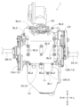
- 1 is a front view of an engine according to an embodiment of the present invention.
- 1 is a longitudinal sectional view of an engine according to an embodiment of the present invention, cut vertically at the position of an intake passage.
- 1 is a longitudinal sectional view of an engine according to an embodiment of the present invention, cut vertically at the position of an exhaust passage.
- 1 is a cross-sectional view of an engine according to an embodiment of the present invention taken along a horizontal line.
- FIG. 1 is a perspective view showing an internal structure of an engine according to an embodiment of the present invention.
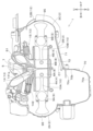
- 1 is a plan view showing an internal structure of an engine according to an embodiment of the present invention.
- 1 is a front view showing an internal structure of an engine according to an embodiment of the present invention.
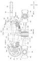
- FIG. 2 is a right side view showing the internal structure of the engine according to the embodiment of the present invention.
- 1 is a left side view showing an internal structure of an engine according to an embodiment of the present invention.
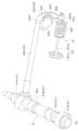
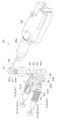
- FIG. FIG. 2 is a perspective view showing a power transmission mechanism that operates the intake valve and the exhaust valve.
- FIG. 2 is a perspective view showing a power transmission mechanism that operates an exhaust valve.
- FIG. 2 is a perspective view showing a power transmission mechanism that operates an intake valve.
- FIG. 4 is a right side view showing a power transmission mechanism that operates the intake valve.
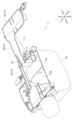
- FIG. 1 is a diagram showing an engine according to an embodiment of the present invention as viewed from below and in front; 1 is a perspective cross-sectional view of an engine according to an embodiment of the present invention, cut horizontally at the position of an oil pan and an inclined portion.
- 1 is a plan view showing a flying device according to an embodiment of the present invention; 1 is a perspective view showing a flying device according to an embodiment of the present invention; 1 is a front view showing a flying device according to an embodiment of the present invention. 1 is a rear view showing a flying device according to an embodiment of the present invention. 2 is an enlarged rear view showing a part of the flying device according to one embodiment of the present invention.
- FIG. 1 is an enlarged plan view showing a portion on which an engine of a flying device according to an embodiment of the present invention is mounted.
- FIG. 1 is an enlarged right side view showing a portion of a flying device according to a first
- the direction indicated by arrow F in the drawings will be referred to as the forward direction
- the direction indicated by arrow B as the rearward direction
- the direction indicated by arrow L as the leftward direction
- the direction indicated by arrow R as the rightward direction
- the direction indicated by arrow U will be referred to as the upward direction
- the direction indicated by arrow D as the downward direction.
- the engine 1 of the embodiment described below is an opposed-piston engine 1 in which two pistons are arranged facing each other inside a cylinder.
- the opposed-piston engine 1 includes an engine block 2 and an output shaft 3 protruding from the engine block 2.
- a cylinder 4 and an intake passage 5 and an exhaust passage 6 communicating with the cylinder 4 are formed inside the engine block 2.
- the engine block 2 is constructed by combining multiple blocks.
- the engine block 2 is constructed from a first block 2A, a second block 2B, and a third block 2C.
- the first block 2A is located at the rear of the engine block 2.
- the third block 2C is located at the front of the engine block 2.
- the second block 2B is disposed between the first block 2A and the second block 2B.
- the first block 2A and the second block 2B are connected by a bolt BL1.
- the second block 2B and the third block 2C are connected by a bolt BL2. Therefore, the engine block 2 can be separated into multiple blocks (the first block 2A, the second block 2B, and the third block 2C) by removing the bolts BL1 and BL2.
- the cylinders 4 are arranged inside the engine block 2 with their cylinder axes facing horizontally (front-to-rear direction).
- the cylinders 4 include a first cylinder 4A and a second cylinder 4B.
- the first cylinder 4A is formed inside the first block 2A.
- the second cylinder 4B is formed inside the second block 2B.
- the first cylinder 4A and the second cylinder 4B are arranged side by side in the horizontal direction (front-to-rear direction).
- the front end of the first cylinder 4A and the rear end of the second cylinder 4B are arranged to butt against each other (in contact).
- the central axes of the first cylinder 4A and the second cylinder 4B are on the same straight line.
- the interior of the first cylinder 4A and the interior of the second cylinder 4B are connected.
- an opening 7 is formed at the upper part of the boundary between the first cylinder 4A and the second cylinder 4B.
- the intake passage 5 and the exhaust passage 6 communicate with the inside of the cylinder 4 through the opening 7.
- the intake passage 5 is opened and closed by an intake valve 14.
- the exhaust passage 6 is opened and closed by an exhaust valve 15.
- the engine block 2 houses a piston 8 and a crankshaft 9.
- the piston 8 is disposed inside the cylinder 4.
- the piston 8 includes a first piston 8A and a second piston 8B.
- the first piston 8A is disposed inside the first cylinder 4A.
- the second piston 8B is disposed inside the second cylinder 4B.
- the first piston 8A and the second piston 8B are disposed side by side in the horizontal direction (front-to-back direction).
- the first piston 8A and the second piston 8B are disposed opposite each other.
- the first piston 8A reciprocates horizontally (front-to-back) within the first cylinder 4A.
- the second piston 8B reciprocates horizontally (front-to-back) within the second cylinder 4B.
- the first piston 8A and the second piston 8B move in directions away from each other or toward each other.
- the first piston 8A and the second piston 8B are collectively referred to as the "piston pair.”
- the upper part (upper front part) of the first piston 8A facing the second piston 8B is curved in a direction away from the second piston 8B.
- the upper part (upper rear part) of the second piston 8B facing the first piston 8A is curved in a direction away from the first piston 8A.
- the opposed piston engine 1 has two piston pairs, each consisting of a first piston 8A and a second piston 8B.
- the two piston pairs are referred to as the first piston pair 81 and the second piston pair 82, respectively.
- the first piston pair 81 and the second piston pair 82 are arranged side by side in the horizontal direction.
- the first piston pair 81 and the second piston pair 82 are arranged side by side in the left-right direction. More specifically, the first piston pair 81 is arranged on the left side, and the second piston pair 82 is arranged on the right side.
- first piston 8A constituting the first piston pair 81 will be referred to as the "first piston 81A”
- second piston 8B constituting the first piston pair 81 will be referred to as the "second piston 81B”
- first piston 8A constituting the second piston pair 82 will be referred to as the "first piston 82A”
- second piston 8B constituting the second piston pair 82 will be referred to as the "second piston 82B.”
- the opposed piston engine 1 of this embodiment has two piston pairs, and therefore four pistons (first piston 81A, second piston 81B, first piston 82A, second piston 82B).
- the number of piston pairs is not limited to two, and may be one, or three or more. Therefore, the number of pistons 8 is not limited to four, and may be two, or six or more.
- the first cylinder 4A includes a first cylinder 4A1 that houses the first piston 81A, and a first cylinder 4A2 that houses the first piston 82A.
- the second cylinder 4B includes a second cylinder 4B1 that houses the second piston 81B, and a second cylinder 4B2 that houses the second piston 82B.
- the opposed piston engine 1 includes four cylinders (first cylinder 4A1, second cylinder 4B1, first cylinder 4A2, second cylinder 4B2) that respectively house four pistons.
- the opposed piston engine 1 of this embodiment is a four-cylinder engine.
- the number of cylinders 4 is set according to the number of pistons 8, and is not limited to four.
- the front end of the first cylinder 4A1 and the rear end of the second cylinder 4B1 are arranged so as to face each other (contact each other).
- the inside of the first cylinder 4A1 and the inside of the second cylinder 4B1 are connected to each other.
- the first cylinder 4A1 and the second cylinder 4B1 are collectively referred to as the "first cylinder structure 41".
- the front end of the first cylinder 4A2 and the rear end of the second cylinder 4B2 are arranged so as to face each other (contact each other).
- the inside of the first cylinder 4A2 and the inside of the second cylinder 4B2 are connected to each other.
- the first cylinder 4A2 and the second cylinder 4B2 are collectively referred to as the "second cylinder structure 42".
- the first cylinder structure 41 and the second cylinder structure 42 are arranged side by side in the left-right direction.
- the intake passage 5 (see FIG. 5) and the exhaust passage 6 (see FIG. 6) are connected to the inside of the cylinder 4.
- the intake passage 5 and the exhaust passage 6 are provided in each of the first cylinder structure 41 and the second cylinder structure 42.
- the intake passage 5 includes a first intake passage that communicates with the inside of the first cylinder structure 41, and a second intake passage that communicates with the inside of the second cylinder structure 42. Two first intake passages and two second intake passages are provided. That is, the first cylinder structure 41 is provided with two first intake passages. The second cylinder structure 42 is also provided with two second intake passages. An intake valve 14 is disposed in each of the two first intake passages and the two second intake passages.
- the exhaust passage 6 includes a first exhaust passage that communicates with the inside of the first cylinder structure 41, and a second exhaust passage that communicates with the inside of the second cylinder structure 42.
- One each of the first exhaust passage and the second exhaust passage is provided.
- An exhaust valve 15 is disposed in each of the first exhaust passage and the second exhaust passage.
- the opposed piston engine 1 has two intake valves 14 and one exhaust valve 15 for one cylinder structure. Since the opposed piston engine 1 has two cylinder structures (first cylinder structure 41 and second cylinder structure 42), it has four intake valves 14 (see symbols 14A, 14B, 14C, and 14D in FIG. 9) and two exhaust valves 15 (see symbols 15A and 15B in FIG. 9).
- crankshaft 9 is connected to the piston 8 by a connecting rod 10.
- the crankshaft 9 has a crank pin 91, a crank journal 92, a crank arm 93, a main shaft 94, and a counterweight 95.
- the crank pin 91 is connected to the connecting rod 10.
- the crank pin 91 and the crank journal 92 are connected by a crank arm 93.
- the main shaft 94 is connected to the output shaft 3.
- the crankshaft 9 includes a first crankshaft 9A and a second crankshaft 9B.
- the first crankshaft 9A and the second crankshaft 9B are arranged at an interval in the arrangement direction of the first piston 8A and the second piston 8B.
- the first crankshaft 9A and the second crankshaft 9B extend parallel to each other.
- the first crankshaft 9A and the second crankshaft 9B extend in a direction perpendicular to the arrangement direction of the first piston 8A and the second piston 8B.
- first piston 8A and the second piston 8B are aligned in the front-to-rear direction. Therefore, the first crankshaft 9A and the second crankshaft 9B are arranged with a gap in the front-to-rear direction. In addition, the first crankshaft 9A and the second crankshaft 9B extend in the left-to-right direction.
- front-to-rear and left-to-right directions change depending on the orientation when the opposed-piston engine 1 is installed.
- the first crankshaft 9A is connected to the first piston 8A by a first connecting rod 10A.
- the second crankshaft 9B is connected to the second piston 8B by a second connecting rod 10B.
- the first crankshaft 9A rotates in conjunction with the reciprocating motion of the first piston 8A.
- the second crankshaft 9B rotates in conjunction with the reciprocating motion of the second piston 8B.
- the rotational power of the crankshaft 9 is taken from the output shaft 3 connected to the main shaft 94.
- the output shaft 3 includes a first output shaft 3A and a second output shaft 3B.
- the first output shaft 3A and the second output shaft 3B are arranged parallel to each other.
- the first output shaft 3A and the second output shaft 3B extend in opposite directions.
- the first output shaft 3A is connected to the main shaft 94 of the first crankshaft 9A via the first coupling 11A.
- the second output shaft 3B is connected to the main shaft 94 of the second crankshaft 9B via the second coupling 11B.
- the opposed piston engine 1 is equipped with a generator 12.
- the generator 12 includes a first generator 12A and a second generator 12B.
- the first generator 12A is attached to the first crankshaft 9A.
- the second generator 12B is attached to the second crankshaft 9B. More specifically, the first generator 12A is attached to the end of the first crankshaft 9A, which is the end opposite the first output shaft 3A.
- the second generator 12B is attached to the end of the second crankshaft 9B, which is the end opposite the second output shaft 3B.
- the first generator 12A is driven by the rotation of the first crankshaft 9A to generate electric power.
- the second generator 12B is driven by the rotation of the second crankshaft 9B to generate electric power.
- the opposed piston engine 1 is equipped with valves 13 for intake or exhaust.
- the valves 13 operate relative to the cylinders 4 to intake or exhaust.
- the valves 13 include the intake valves 14 and exhaust valves 15 described above.
- the intake valves 14 are disposed in the intake passages 5 that communicate with the interior of the cylinders 4.
- the exhaust valves 15 are disposed in the exhaust passages 6 that communicate with the interior of the cylinders 4.
- the intake valves 14 are disposed on the first crankshaft 9A side.
- the exhaust valves 15 are disposed on the second crankshaft 9B side. However, the intake valves 14 may be disposed on the second crankshaft 9B side, and the exhaust valves 15 may be disposed on the first crankshaft 9A side.
- the opposed piston engine 1 is equipped with a power transmission mechanism 20 that transmits the rotational power of the first crankshaft 9A to the valve 13 to operate the valve 13.
- Figure 13 is a diagram showing the configuration of the power transmission mechanism 20.
- the power transmission mechanism 20 transmits the rotational power of the first crankshaft 9A to the exhaust valve 15 and the intake valve 14 to operate the exhaust valve 15 and the intake valve 14.
- the power transmission mechanism 20 has a camshaft 21, a push rod 22 and a rocker arm 23.
- the camshaft 21 is composed of a single camshaft arranged on the first crankshaft 9A side (rear side) in the arrangement direction (front-rear direction) of the first piston 8A and the second piston 8B. In other words, the camshaft 21 is arranged on the first crankshaft 9A side, but not on the second crankshaft 9B side.
- the camshaft 21 extends parallel to the first crankshaft 9A.
- the camshaft 21 is arranged above the first crankshaft 9A.
- the camshaft 21 may be disposed at a position different from above the first crankshaft 9A (for example, a position shifted forward or backward from above the first crankshaft 9A). Also, the camshaft 21 may be disposed on the second crankshaft 9B side instead of the first crankshaft 9A side. In this case, the camshaft 21 is disposed above the second crankshaft 9B, etc.
- a first gear 25 is attached to the first crankshaft 9A.
- a second gear 26 is attached to the camshaft 21.
- the first gear 25 and the second gear 26 mesh with each other.
- the camshaft 21 rotates together with the second gear 26 that meshes with the first gear 25. In this way, the camshaft 21 rotates in conjunction with the rotation of the first crankshaft 9A.
- the rotation direction of the camshaft 21 is opposite to the rotation direction of the first crankshaft 9A.
- a third gear 27 is attached to the camshaft 21.
- a fourth gear 28 is attached to the second crankshaft 9B.
- An endless (loop-shaped) belt 29 is stretched between the third gear 27 and the fourth gear 28.
- the camshaft 21 has a shaft 30 and a cam 31 provided on the shaft 30.
- a plurality of cams 31 are provided at intervals in the longitudinal direction (left-right direction) of the shaft 30.
- the plurality of cams 31 include a first cam 31A, a second cam 31B, a third cam 31C, and a fourth cam 31D (see also FIG. 8).
- the four cams are provided at intervals from one another in the extension direction of the camshaft 21.
- the first cam 31A and the second cam 31B are provided near both ends of the camshaft 21, spaced apart from each other.
- the first cam 31A is provided near one end (left part) of the shaft 30.
- the second cam 31B is provided near the other end (right part) of the shaft 30.
- the third cam 31C and the fourth cam 31D are provided between the first cam 31A and the second cam 31B.
- the third cam 31C is provided next to the first cam 31A.
- the fourth cam 31D is provided next to the second cam 31B.
- the first cam 31A and the second cam 31B are arranged with a phase difference of 180 degrees around the axis of the shaft 30.
- the third cam 31C and the fourth cam 31D are arranged with a phase difference of 180 degrees around the axis of the shaft 30.
- the third cam 31C and the first cam 31A are arranged with a phase difference of 90 degrees around the axis of the shaft 30.
- the fourth cam 31D and the second cam 31B are arranged with a phase difference of 90 degrees around the axis of the shaft 30.
- the push rod 22 extends from the first crankshaft 9A side to the second crankshaft 9B side.
- One end 22a (see Figure 11) of the push rod 22 is disposed on the first crankshaft 9A side (rear side).
- the other end 22b (see Figure 11) of the push rod 22 is disposed on the second crankshaft 9B side (front side).
- One end 22a of the push rod 22 is disposed in contact with the cam 31 (first cam 31A or second cam 31B) of the camshaft 21.
- the other end 22b of the push rod 22 is connected to the rocker arm 23.
- the push rod 22 includes a first push rod 22A and a second push rod 22B.
- the first push rod 22A and the second push rod 22B are arranged at a distance from each other in the extension direction (left-right direction) of the camshaft 21.
- the first push rod 22A and the second push rod 22B are arranged parallel to each other.
- the first push rod 22A extends in the front-rear direction at one end side (left side) of the camshaft 21.
- the second push rod 22B extends in the front-rear direction at the other end side (right side) of the camshaft 21.
- first push rod 22A is disposed in contact with the first cam 31A.
- second push rod 22B is disposed in contact with the second cam 31B.
- the first cam 31A and the second cam 31B rotate together with the camshaft 21.
- the first cam 31A rotates together with the camshaft 21
- the first push rod 22A reciprocates.
- the second cam 31B rotates together with the camshaft 21
- the second push rod 22B reciprocates. In this way, the push rods 22 (the first push rod 22A and the second push rod 22B) reciprocate in conjunction with the rotation of the single camshaft 21.
- the rocker arm 23 connects the push rod 22 and the valve 13. More specifically, the rocker arm 23 connects the other end 22b (see FIG. 11) of the push rod 22 and the valve 13 on the second crankshaft 9B side.
- the rocker arm 23 connects the other end 22b of the push rod 22 and one of the intake valve 14 and the exhaust valve 15. In this embodiment, the rocker arm 23 connects the other end 22b of the push rod 22 and the exhaust valve 15.
- the intake valve 14 may be arranged on the second crankshaft 9B side, and the other end 22b of the push rod 22 may be connected to the intake valve 14.
- the exhaust valve 15 is arranged on the first crankshaft 9A side.
- the rocker arm 23 includes a first rocker arm 23A and a second rocker arm 23B.
- the first rocker arm 23A is connected to the first push rod 22A.
- the second rocker arm 23B is connected to the second push rod 22B.
- the first rocker arm 23A connects the other end of the first push rod 22A to the exhaust valve 15 (first exhaust valve 15A described later).
- the second rocker arm 23B connects the other end of the second push rod 22B to the exhaust valve 15 (second exhaust valve 15B described later).
- the rocker arm 23 has a cylindrical portion 23a and an arc-shaped portion 23b.
- a shaft body 23c is inserted into the cylindrical portion 23a.
- a fixing plate 23d is attached to the end of the shaft body 23c. As shown in Figure 2, the fixing plate 23d is fixed to the engine block 2. As a result, the shaft body 23c is positioned and supported relative to the engine block 2.
- the arc-shaped portion 23b has a first portion 23b1 and a second portion 23b2.
- the first portion 23b1 and the second portion 23b2 are provided on opposite sides of the cylindrical portion 23a.
- the arc-shaped portion 23b oscillates around the shaft body 23c as the push rod 22 reciprocates.
- the first portion 23b1 and the second portion 23b2 rotate in opposite directions around the cylindrical portion 23a.
- the first portion 23b1 of the arc-shaped portion 23b is connected to the other end 22b of the push rod 22.
- the second portion 23b2 abuts against the base end of one of the intake valve 14 and the exhaust valve 15.
- the one valve is the exhaust valve 15
- the other valve is the intake valve 14. Therefore, in this embodiment, the second portion 23b2 of the arc-shaped portion 23b of the rocker arm 23 abuts against the base end 151c of the exhaust valve 15.
- the base end 151c of the exhaust valve 15, which is one of the intake valve 14 and exhaust valve 15, abuts against the rocker arm 23.
- the base end of the intake valve 14, which is the other valve abuts against a rocking member 47 (described later) that is linked to a cam 31.
- the cams 31 that are linked to the rocking member 47 are the third cam 31C and the fourth cam 31D.
- the linkage mechanism 45 has a support shaft 46 and a swinging member 47.
- the support shaft 46 extends parallel to the camshaft 21 and the crankshaft 9.
- the support shaft 46 is supported by the engine block 2.
- the support shaft 46 is disposed on the first crankshaft 9A side (rear side) in the arrangement direction (front-rear direction) of the first piston 8A and the second piston 8B.
- the support shaft 46 is disposed above the first crankshaft 9A and near the camshaft 21.
- the oscillating member 47 is attached to the support shaft 46.
- the oscillating member 47 can oscillate around the axis of the support shaft 46.
- the oscillating member 47 has a cylindrical portion 47a and an arc-shaped portion 47b.
- the support shaft 46 is inserted into the cylindrical portion 47a.
- the arc-shaped portion 47b extends downward in an arc shape from the cylindrical portion 47a.
- the arc-shaped portion 47b has a first abutment portion 47b1 that abuts against the cam 31, and a second abutment portion 47b2 that abuts against the stem 141b (described later) of the intake valve 14.
- the oscillating member 47 includes a first oscillating member 47A and a second oscillating member 47B.
- the first oscillating member 47A and the second oscillating member 47B have the same shape.
- the first oscillating member 47A has two cylindrical portions 47a and two arc-shaped portions 47b. Therefore, the first oscillating member 47A has two first abutment portions 47b1 and two second abutment portions 47b2.
- the second oscillating member 47B also has two cylindrical portions 47a and two arc-shaped portions 47b. Therefore, the second oscillating member 47B also has two first abutment portions 47b1 and two second abutment portions 47b2.
- the intake valve 14 has a valve body 141 having an umbrella portion 141a and a stem 141b, and a spring 142 that biases the valve body 141.
- the umbrella portion 141a is provided at the tip of the stem 141b (the tip of the intake valve 14).
- the second abutment portion 47b2 of the oscillating member 47 can abut against the base end of the stem 141b.
- the spring 142 biases the valve body 141 in the direction that closes the intake valve 14 (the direction that closes the intake passage 5).
- the exhaust valve 15 has a valve body 151 having an umbrella portion 151a and a stem 151b, and a spring 152 that biases the valve body 151.
- the umbrella portion 151a is provided at the tip of the stem 151b (the tip of the exhaust valve 15).
- the spring 152 biases the valve body 151 in the direction in which the exhaust valve 15 is closed (the direction in which the exhaust passage 6 is closed).
- the intake valve 14 and exhaust valve 15 operate in conjunction with the rotation of a single camshaft 21. Below, the operation of the intake valve 14 and exhaust valve 15 in conjunction with the rotation of a single camshaft 21 will be explained.
- the base end of the intake valve 14 (base end 141d of stem 141b) is positioned so that it can abut against the second abutment portion 47b2 of the oscillating member 47 when the oscillating member 47 oscillates.
- the cam 31 (third cam 31C or fourth cam 31D) of the camshaft 21 can abut against the first abutment portion 47b1 of the oscillating member 47 by rotating. Therefore, the base end of the intake valve 14 (base end of stem 141b) can abut against the cam 31 (third cam 31C or fourth cam 31D) via the oscillating member 47.
- the base end of the exhaust valve 15 (base end 151c of stem 151b) abuts against the rocker arm 23.
- One end 22a of the push rod 22 is arranged in abutment against the cam 31 (first cam 31A or second cam 31B). Therefore, when the cam 31 rotates together with the camshaft 21, the one end 22a of the push rod 22 abutting against the cam 31 is pushed by the cam 31. This causes the push rod 22 to move toward the second crankshaft 9B (the right side in FIG. 14).
- the arc-shaped portion 23b of the rocker arm 23 swings about the shaft body 23c as a fulcrum, and the base end 151c of the stem 151b abutting against the second portion 23b2 is pushed by the second portion 23b2.
- the spring 152 contracts and the valve body 151 moves. This causes the umbrella portion 151a, which had been closing the exhaust passage 6, to move and the exhaust valve 15 opens (the exhaust passage 6 is opened).
- the exhaust valve 15 includes a first exhaust valve 15A and a second exhaust valve 15B.
- the first exhaust valve 15A and the second exhaust valve 15B are arranged at a distance from each other in the extension direction of the camshaft 21.
- the exhaust valves 15 (first exhaust valve 15A, second exhaust valve 15B) are arranged between the first push rod 22A and the second push rod 22B in the extension direction of the camshaft 21.
- the first exhaust valve 15A is arranged on the first push rod 22A side.
- the second exhaust valve 15B is arranged on the second push rod 22B side.
- the intake valves 14 include a first intake valve 14A, a second intake valve 14B, a third intake valve 14C, and a fourth intake valve 14D.
- the first intake valve 14A, the second intake valve 14B, the third intake valve 14C, and the fourth intake valve 14D are arranged at intervals from each other in the extension direction of the camshaft 21.
- the intake valves 14 are arranged between the first push rod 22A and the second push rod 22B in the extension direction of the camshaft 21.
- the first intake valve 14A and the second intake valve 14B are arranged on the first push rod 22A side.
- the third intake valve 14C and the fourth intake valve 14D are arranged on the second push rod 22B side.
- the first intake valve 14A, the second intake valve 14B, the third intake valve 14C, and the fourth intake valve 14D are arranged in this order from the first push rod 22A side to the second push rod 22B side.
- the first intake valve 14A and the second intake valve 14B face the first exhaust valve 15A.
- the third intake valve 14C and the fourth intake valve 14D face the second exhaust valve 15B.
- the intake valves 14 abut against the oscillating member 47 (see FIG. 15, etc.). More specifically, of the four intake valves 14, two abut against the first oscillating member 47A, and the remaining two abut against the second abutment portion 47b2. Specifically, as shown in FIG. 13, the first intake valve 14A and the second intake valve 14B abut against the second abutment portion 47b2 of the first oscillating member 47A. The third intake valve 14C and the fourth intake valve 14D abut against the second abutment portion 47b2 of the second oscillating member 47B.
- the first intake valve 14A abuts against one of the two second abutment portions 47b2 of the first oscillating member 47A.
- the second intake valve 14B abuts against the other of the two second abutment portions 47b2 of the first oscillating member 47A. This allows the first intake valve 14A and the second intake valve 14B to operate simultaneously in response to the oscillation of one first oscillating member 47A.
- the third intake valve 14C abuts against one of the two second abutment portions 47b2 of the second oscillating member 47B.
- the fourth intake valve 14D abuts against the other of the two second abutment portions 47b2 of the second oscillating member 47B. This allows the third intake valve 14C and the fourth intake valve 14D to operate simultaneously in response to the oscillation of one second oscillating member 47B.
- the first intake valve 14A and the second intake valve 14B are respectively arranged in two first intake passages that communicate with the interior of the first cylinder structure 41 described above.
- the third intake valve 14C and the fourth intake valve 14D are respectively arranged in two second intake passages that communicate with the interior of the second cylinder structure 42 described above.
- the first exhaust valve 15A is disposed in a first exhaust passage that communicates with the interior of the first cylinder structure 41 described above.
- the second exhaust valve 15B is disposed in a second exhaust passage that communicates with the interior of the second cylinder structure 42 described above.
- the opposed piston engine 1 is provided with two intake valves 14 and one exhaust valve 15 for one cylinder structure.
- two intake valves first intake valve 14A and second intake valve 14B
- one exhaust valve first exhaust valve 15A
- two intake valves third intake valve 14C and fourth intake valve 14D
- one exhaust valve second exhaust valve 15B
- one valve is the intake valve 14 and the other valve is the exhaust valve 15, but one valve may be the intake valve 14 and the other valve may be the exhaust valve 15.
- the base end of the exhaust valve 15 is capable of abutting against the second abutment portion 47b2 of the oscillating member 47, and the exhaust valve 15 operates in conjunction with the oscillating member 47.
- the base end of the intake valve 14 abuts against the rocker arm 23, and the intake valve 14 operates in conjunction with the rocker arm 23.
- the power transmission mechanism 20 is provided across the first crankshaft 9A and the second crankshaft 9B in the arrangement direction of the first piston 8A and the second piston 8B.
- the position of the power transmission mechanism 20 in the arrangement direction of the first piston 8A and the second piston 8B overlaps with the first crankshaft 9A and the second crankshaft 9B.
- the position of one end (front end) of the power transmission mechanism 20 in the arrangement direction (front-rear direction) of the first piston 8A and the second piston 8B overlaps with the first crankshaft 9A.
- the position of the other end (rear end) of the power transmission mechanism 20 in the arrangement direction (front-rear direction) of the first piston 8A and the second piston 8B overlaps with the second crankshaft 9B.
- the rocker arm 23 of the power transmission mechanism 20 overlaps with the second crankshaft 9B in the direction in which the first piston 8A and the second piston 8B are aligned.
- the camshaft 21 of the power transmission mechanism 20 overlaps with the first crankshaft 9A in the direction in which the first piston 8A and the second piston 8B are aligned.
- one end 22a (front end) of the push rod 22 of the power transmission mechanism 20 overlaps with the first crankshaft 9A in the direction in which the first piston 8A and the second piston 8B are aligned.
- the other end 22b (rear end) of the push rod 22 of the power transmission mechanism 20 overlaps with the second crankshaft 9B in the direction in which the first piston 8A and the second piston 8B are aligned.
- the power transmission mechanism 20 is arranged such that the position of the first piston 8A and the second piston 8B in the alignment direction overlaps with the crank arm 93 and crank pin 91 of the first crankshaft 9A, and overlaps with the crank arm 93 and crank pin 91 of the second crankshaft 9B.
- the opposed piston engine 1 is equipped with a spark plug 50.
- the spark plug 50 is disposed near a space S1 (see Figures 11 and 12) formed between the front upper part of the first piston 8A and the rear upper part of the second piston 8B when the first piston 8A and the second piston 8B are in close proximity to each other.
- the spark plug 50 includes a first spark plug 50A and a second spark plug 50B.
- the first spark plug 50A is provided at a position corresponding to the first piston pair 81 (see Figure 7).
- the second spark plug 50B is provided at a position corresponding to the second piston pair 82 (see Figure 7).
- the opposed piston engine 1 is equipped with an injection nozzle 51.
- the injection nozzle 51 is disposed above the first crankshaft 9A.
- the injection nozzle 51 injects fuel toward a space S1 (see Figures 11 and 12) formed between the front upper part of the first piston 8A and the rear upper part of the second piston 8B when the first piston 8A and the second piston 8B are in close proximity to each other.
- the injection nozzle 51 includes a first injection nozzle 51A and a second injection nozzle 51B.
- the first injection nozzle 51A is provided corresponding to the first piston pair 81.
- the second injection nozzle 51B is provided corresponding to the second piston pair 82.
- the first injection nozzle 51A and the second injection nozzle 51B are connected by a connecting member 52.
- the opposed piston engine 1 is a four-stroke engine that operates by repeating an intake stroke, a compression stroke, a combustion stroke, and an exhaust stroke.
- the intake stroke the intake valve 14 is opened just before the first piston 8A and the second piston 8B move away from each other, and a mixture of air and fuel is sucked into the cylinder 4 from the injection nozzle 51.
- the intake valve 14 is closed.
- the compression stroke the first piston 8A and the second piston 8B move toward each other, compressing the mixture sucked into the cylinder 4.
- the compressed mixture is ignited by a spark generated by the spark plug 50, and the first piston 8A and the second piston 8B move away from each other due to the combustion of the mixture.
- the exhaust stroke the exhaust valve 15 is opened slightly before the first piston 8A and the second piston 8B start to move toward each other, and the combustion gas is discharged from the cylinder 4.
- the exhaust valve 15 closes immediately after the exhaust of the combustion gases is completed (when the first piston 8A and the second piston 8B are at their closest positions).
- the opposed piston engine 1 rotates the first crankshaft 9A and the second crankshaft 9B in opposite directions.
- the rotational power of the first crankshaft 9A is taken from the first output shaft 3A.
- the rotational power of the second crankshaft 9B is taken from the second output shaft 3B.
- the first output shaft 3A and the second output shaft 3B of the opposed piston engine 1 rotate in opposite directions.
- the opposed piston engine 1 is equipped with a decompression device 60.
- the decompression device 60 reduces the pressure in the cylinder 4 when the opposed piston engine 1 is started. More specifically, the decompression device 60 reduces the pressure in the cylinder 4 by releasing the air compressed in the cylinder 4 to the outside of the cylinder 4 when the opposed piston engine 1 is started (or immediately before starting). The air released by the decompression device 60 is exhausted to the outside of the engine block 2 through the exhaust passage 6.
- the decompression device 60 to reduce the pressure in the cylinder 4 when the opposed piston engine 1 is started, the load on the starter (cell motor) of the opposed piston engine 1 mounted on the flight device 101 can be reduced.
- the decompression device 60 has a decompression valve 61.
- the decompression valve 61 moves relative to the cylinder 4, allowing the air compressed in the cylinder 4 to escape from the cylinder 4.
- the decompression valve 61 has a decompression valve body 61a and a spring 61b that biases the decompression valve body 61a.
- the spring 61b biases the decompression valve body 61a in the direction in which the decompression valve 61 closes.
- the decompression valve body 61a of the decompression valve 61 moves relative to the cylinder 4 against the biasing force of the spring 61b by the drive of an actuator 65, which will be described later.
- the decompression valve 61 includes a first decompression valve 61A and a second decompression valve 61B. As shown in FIG. 9, the first decompression valve 61A and the second decompression valve 61B are arranged parallel to each other with a gap in the extension direction (left-right direction) of the camshaft 21.
- the first decompression valve 61A can release air in the first cylinder structure 41 (see FIG. 7) to the outside.
- the second decompression valve 61B can release air in the second cylinder structure 42 (see FIG. 7) to the outside.
- the decompression device 60 further includes a connecting member 62, a shaft body 63, an oscillating cam 64, and an actuator 65.
- the connecting member 62 connects the decompression valve body 61a of the first decompression valve 61A (hereinafter referred to as the "first decompression valve body 61a1”) and the decompression valve body 61a of the second decompression valve 61B (hereinafter referred to as the "second decompression valve body 61a2").
- the cam surface 64a of the oscillating cam 64 abuts against the connecting member 62.
- the cam surface 64a is formed in a substantially arc shape in a plan view.
- the oscillating cam 64 is fixed to a shaft body 63 that extends in the vertical direction.
- the shaft body 63 rotates around an axis in the vertical direction.
- the lower part of the shaft body 63 is disposed inside the engine block 2, and the upper part of the shaft body 63 is disposed outside the engine block 2 (see FIG. 2).
- the cam surface 64a is not an arc surface with a constant distance from the shaft body 63, but rather the distance from the shaft body 63 gradually increases from one end 64b to the other end 64c along the arc.
- the oscillating cam 64 oscillates with the rotation of the shaft body 63 and presses the decompression valve 61.
- the oscillating cam 64 oscillates in one direction (the direction of arrow A3) with the rotation of the shaft body 63, it presses the decompression valve 61 via the connecting member 62.
- the actuator 65 is an electric actuator. More specifically, the actuator 65 is an electric cylinder device. The operation of the actuator 65 is controlled by a control device (not shown) that controls the operation of the engine 1. As shown in Figures 9, 11, and 12, the actuator 65 is disposed in a position overlapping above the second crankshaft 9B. As shown in Figures 1 and 2, the actuator 65 is disposed outside the engine block 2.
- the actuator 65 has a rod 65a.
- the rod 65a can extend and retract in a direction toward (rearward) and away from (forward) the decompression valve 61.
- the rod 65a extends in the direction in which the first piston 8A and the second piston 8B are arranged (front-to-back direction).
- One end of a connection member 66 is attached to the tip of the rod 65a.
- the other end of the connection member 66 is attached to a rocking plate 67.
- the rocking plate 67 is attached to the upper part of the shaft body 63.
- the rocking plate 67 has a first attachment portion 67a attached to the connection member 66 and a second attachment portion 67b attached to the rocking plate 67.
- FIGS 9 and 17 show the state in which the rod 65a of the actuator 65 is extended.
- the decompression valve 61 is closed.
- the oscillating plate 67 oscillates in the direction of arrow A1 with the second mounting portion 67b as the fulcrum.
- the shaft 63 rotates around its axis in the direction of arrow A2, and the oscillating cam 64 oscillates in the direction of arrow A3.
- the connecting member 62 is pressed by the cam surface 64a of the oscillating cam 64.
- the decompression valve body 61a is pressed.
- the decompression valve body 61a moves in the direction of arrow A4 against the biasing force of the spring 61b, and the decompression valve 61 opens.
- the oscillating plate 67 oscillates in the direction opposite to the arrow A1, with the second mounting portion 67b as the fulcrum. Then, the shaft 63 rotates around its axis in the direction opposite to the arrow A2, and the oscillating cam 64 oscillates in the direction opposite to the arrow A3. This releases the pressure on the connecting member 62 by the cam surface 64a of the oscillating cam 64. Then, the decompression valve body 61a moves in the direction opposite to the arrow A4 due to the biasing force of the spring 61b, and the decompression valve 61 closes.
- first decompression valve body 61a1 and the second decompression valve body 61a2 are connected by a connecting member 62, so the first decompression valve body 61a1 and the second decompression valve body 61a2 move together. This allows the two decompression valves 61 to be operated (opened and closed) simultaneously by a single actuator 65.
- a configuration may be adopted in which the decompression valve 61 opens when the rod 65a expands and closes when the rod 65a contracts.
- Such a configuration can be realized, for example, by making the distance of the cam surface 64a from the shaft body 63 gradually smaller from one end 64b to the other end 64c in the direction along the arc.
- At least a part of the power transmission mechanism 20 is arranged on the first crankshaft 9A side, and the decompression device 60 is arranged on the second crankshaft 9B side.
- at least a part of the power transmission mechanism 20 and the decompression device 60 are arranged separately on the first crankshaft 9A side and the second crankshaft 9B side.
- "at least a part of the power transmission mechanism 20" includes the camshaft 21. Therefore, the camshaft 21 and the decompression device 60 are arranged separately on the first crankshaft 9A side and the second crankshaft 9B side.
- the camshaft 21 and one end 22a of the push rod 22 are arranged separately on the first crankshaft 9A side and the second crankshaft 9B side.
- the decompression valve 61 is disposed between the first push rod 22A and the second push rod 22B in the extension direction (left-right direction) of the camshaft 21.
- the decompression valve 61 is also disposed between the first exhaust valve 15A and the second exhaust valve 15B in the extension direction of the camshaft 21.
- the decompression valve 61 is also disposed between the first crankshaft 9A and the second crankshaft 9B in the arrangement direction (front-rear direction) of the first piston 8A and the second piston 8B, and is disposed closer to the second crankshaft 9B than the first crankshaft 9A.
- the shaft 63 of the decompression device 60 is disposed between the first rocker arm 23A and the second rocker arm 23B.
- the shaft 63 extends in the vertical direction between the first rocker arm 23A and the second rocker arm 23B.
- the shaft 63 is also disposed above the first crankshaft 9A.
- the shaft 63 is disposed in a position that overlaps with the second crankshaft 9B in the arrangement direction (front-rear direction) of the first piston 8A and the second piston 8B.
- an oil pan 70 is provided below the engine block 2.
- the oil pan 70 is provided only on one side (the left side of the paper in Figure 3) of the engine block 2 in the width direction (front-rear direction).
- the side where the oil pan 70 is provided protrudes downward further than the side where the oil pan 70 is not provided (the right side of the paper in Figure 3).
- the lower end (bottom surface) of the side where the oil pan 70 is provided is lower than the lower end (bottom surface) of the side where the oil pan 70 is not provided.
- the "width direction of the engine block 2" is the direction in which the first piston 8A and the second piston 8B are arranged (front-to-rear direction). Furthermore, “one side of the width direction of the engine block 2" is the rear side of the engine block 2. “The other side of the width direction of the engine block 2" is the front side of the engine block 2. In other words, the oil pan 70 is provided only in the rear part of the engine block 2.
- “one side in the width direction of the engine block 2" may be the front side of the engine block 2.
- the oil pan 70 is provided only in the front part of the front and rear parts of the engine block 2.
- the "width direction of the engine block 2" is not limited to the arrangement direction of the first piston 8A and the second piston 8B, and may be, for example, a direction perpendicular to the arrangement direction (left-right direction). In this case, the oil pan 70 is provided only in the left part or only in the right part of the left and right parts of the engine block 2.
- the first crankshaft 9A and the second crankshaft 9B are arranged parallel to each other with a gap in the arrangement direction of the first piston 8A and the second piston 8B (see FIG. 9, etc.).
- the arrangement direction of the first piston 8A and the second piston 8B is the width direction of the engine block 2. Therefore, the first crankshaft 9A and the second crankshaft 9B are arranged parallel to each other with a gap in the width direction of the engine block 2.
- the first crankshaft 9A is arranged on one side of the engine block 2 in the width direction.
- the second crankshaft 9B is arranged on the other side of the engine block 2 in the width direction. Therefore, the oil pan 70 is provided only on the first crankshaft 9A side of the first crankshaft 9A and the second crankshaft 9B.
- the camshaft 21 is disposed only on the first crankshaft 9A side in the direction in which the first piston 8A and the second piston 8B are aligned. Therefore, the oil pan 70 is disposed on the camshaft 21 side in the direction in which the first piston 8A and the second piston 8B are aligned. The oil pan 70 is disposed in a position overlapping the lower side of the camshaft 21. In other words, the camshaft 21 is disposed above the oil pan 70.
- the oil pan 70 is integrated with the engine block 2.
- the oil pan 70 is made of the same material as the engine block 2.
- This same material is a material that integrally comprises a portion that constitutes the engine block 2 (upper portion) and a portion that constitutes the oil pan 70 (lower portion).
- the oil pan 70 and the engine block 2 may be made of separate materials, and the material that constitutes the oil pan 70 may be connected to the lower portion of the material that constitutes the engine block 2.
- the oil pan 70 is integrated with the first block 2A of the engine block 2.
- the oil pan 70 is made of the same material (single material) as the first block 2A.
- the oil pan 70 is only located below the first block 2A.
- the engine block 2 has an inclined portion 71.
- the inclined portion 71 is formed in the lower portion of the engine block 2.
- the inclined portion 71 is formed in a block that is different from the block (first block 2A) in which the oil pan 70 is disposed below (integrated with the lower portion). More specifically, the inclined portion 71 is formed in a block that is adjacent to the block (first block 2A) in which the oil pan 70 is disposed below (integrated with the lower portion).
- the inclined portion 71 is formed in the lower portion of the second block 2B among the first block 2A, second block 2B, and third block 2C.
- the oil pan 70 is disposed below (integrated with) one of the multiple blocks (first block 2A).
- the inclined portion 71 is formed at the bottom of another block (second block 2B) adjacent to the one of the multiple blocks (first block 2A).
- the inner bottom surface 72 of the inclined portion 71 is inclined so as to become lower from the other side (front side) to one side (rear side) in the width direction of the engine block 2.
- the inner bottom surface 72 of the inclined portion 71 is connected to an inner wall surface 70b that rises from the inner bottom surface 70a of the oil pan 70.
- the inclined portion 71 is provided in the second block 2B of the engine block 2.
- the inner bottom surface of the third block 2C of the engine block 2 is located higher than the inner bottom surface of the second block 2B.
- the inner bottom surface 72 of the inclined portion 71 is inclined downward from the third block 2C side of the second block 2B toward the first block 2A side.
- the height of the upper end of the inner bottom surface 72 of the inclined portion 71 is equal to the height of the inner bottom surface of the third block 2C.
- the height of the lower end of the inner bottom surface 72 of the inclined portion 71 is equal to the height of the upper end of the inclined portion 71 side (front side) of the oil pan 70.
- a protruding plate 70c is provided on the inner wall surface 70b that rises from the inner bottom surface 70a of the oil pan 70.
- the protruding plate 70c is provided on the inner wall surface 70b on the front side of the oil pan 70 (the other side in the width direction of the engine block 2).
- the protruding plate 70c is provided to protrude from the inner wall surface 70b of the oil pan 70.
- the protruding plate 70c extends in a direction (rearward) away from the inner wall surface 70b.
- the protruding plate 70c extends horizontally, but may be inclined downward as it moves away from the inner wall surface 70b.
- the protruding plate 70c is provided over the entire length in the depth direction (left-right direction) perpendicular to the width direction of the engine block 2. This improves the strength of the oil pan 70.
- the protruding plate 70c is provided on the upper part of the inner wall surface 70b of the oil pan 70.
- the upper surface of the protruding plate 70c is provided at a height slightly lower than the lower end of the inner bottom surface 72 of the inclined portion 71.
- the oil flowing along the inner bottom surface 72 of the inclined portion 71 first flows down to the upper surface of the protruding plate 70c, and then flows down from the protruding plate 70c toward the inner bottom surface 70a of the oil pan 70.
- This allows the protruding plate 70c to reduce the momentum (flow rate) of the oil flowing down along the inclined portion 71 toward the oil pan 70.
- the oil flowing down along the inclined portion 71 toward the oil pan 70 can be dispersed in the depth direction of the engine block 2 before flowing down.
- the inclined portion 71 is provided on only a portion of the engine block 2 in the depth direction (left-right direction). Specifically, the inclined portion 71 is provided on one side of the engine block 2 in the depth direction perpendicular to the width direction. In this embodiment, the inclined portion 71 is provided on the left part of the engine block 2.
- the width W1 of the inclined portion 71 in the depth direction (left-right direction) of the engine block 2 is smaller than the overall width of the engine block 2. Also, the width W1 of the inclined portion 71 in the depth direction (left-right direction) of the engine block 2 is smaller than the overall width of the oil pan 70. As shown in Figures 4 and 19, the inclined portion 71 is formed with a U-shaped cross section. As a result, the inner bottom surface 72 of the inclined portion 71 is located lower than the inner bottom surface of the portion of the second block 2B where the inclined portion 71 is not provided.
- the inclined portion 71 in a narrow U-shaped cross section, the oil that has accumulated inside the inclined portion 71 can be quickly and reliably drained toward the oil pan 70.
- the opposed piston engine 1 can be used, for example, as a drive source for a flying device.
- the opposed piston engine 1 can also be used as a drive source for devices other than flying devices, for example, automobiles (including work vehicles), ships, and other industrial machines.
- the flying device 101 is an unmanned flying device. More specifically, the flying device 101 is a multicopter known as a drone.
- the flying device 101 may fly by remote control using wireless or wired communication, or it may fly by autonomous control without relying on a remote device.
- FIGS. 20 to 26 are diagrams showing an example of a flying device 101 equipped with the opposed piston engine 1 described above.
- the flying device 101 comprises an airframe 102 and a rotor 103 attached to the airframe 102.
- the airframe 102 has a main body 106 and a number of arms 107 extending from the main body 106.
- the main body 106 is constructed by combining multiple frame members. As shown in Figures 20 to 26, the opposed-piston engine 1 is mounted on the main body 106. A skid 110 is attached to the bottom of the main body 106. The skid 110 touches the ground when the flight device 101 lands, and supports the aircraft 102 by floating it above the landing surface, such as the ground.
- the arms 107 extend in a direction away from the main body 106 in a plan view.
- a rotor 103 and a motor 105 are attached to each of the arms 107.
- the rotor 103 includes a main rotor 103A and a sub-rotor 103B.
- the main rotor 103A is a rotor for generating lift to lift the aircraft 102.
- the sub-rotor 103B is a rotor for controlling the attitude of the aircraft 102.
- the main rotor 103A is attached to the main body 106.
- the sub-rotor 103B is attached to an arm 107.
- the main rotor 103A rotates by the driving force supplied from the opposed piston engine 1.
- the sub-rotor 103B rotates by the driving force supplied from the motor 105.
- two main rotors 103A are arranged around the aircraft body 102 in a plan view.
- the two main rotors 103A are referred to as the first main rotor 103A1 and the second main rotor 103A2, respectively.
- the first main rotor 103A1 and the second main rotor 103A2 are arranged in symmetrical positions on either side of the center of the aircraft body 102.
- the first main rotor 103A1 and the second main rotor 103A2 rotate in opposite directions.
- each sub-rotor 103B has an upper rotor 103BU and a lower rotor 103BL.
- the motor 105 that supplies driving force to the sub rotor 103B is an electric motor that is driven by power supplied from a battery 146 described below.
- the motor 105 includes a first motor 105A and a second motor 105B.
- the first motor 105A supplies driving force to the upper rotor 103BU.
- the second motor 105B supplies driving force to the lower rotor 103BL.
- the first output shaft 3A and the second output shaft 3B of the opposed piston engine 1 extend protruding from the main body 106.
- the first output shaft 3A supplies driving force to the first main rotor 103A1.
- the second output shaft 3B supplies driving force to the second main rotor 103A2.
- the rotation of the first output shaft 3A is transmitted to the first main rotor 103A1 via a first power transmission unit 138 (see Figures 22 and 23) consisting of a gear mechanism or the like. This causes the first main rotor 103A1 to rotate.
- the rotation of the second output shaft 3B is transmitted to the second main rotor 103A2 via a second power transmission unit 139 (see Figures 22 and 23) consisting of a gear mechanism or the like.
- first main rotor 103A1 and second main rotor 103A2 are driven by two output shafts (first output shaft 3A, second output shaft 3B) of one opposed-piston engine 1.
- the flying device 101 is equipped with a radiator 140 as a cooling device that water-cools the engine 1.
- the radiator 140 is disposed on the sides (left and right) of the main body 106.
- the flying device 101 also has an air guide member 144 that guides the downward airflow generated by the rotation of the main rotor 103A toward the radiator 140.
- the flight device 101 is equipped with a battery 146 that stores power supplied to the motor 105.
- the battery 146 includes a first battery 146A and a second battery 146B.
- the first battery 146A is disposed on one side (left) of the opposed piston engine 1 in a plan view.
- the second battery 146B is disposed on the other side (right) of the opposed piston engine 1 in a plan view.
- the two batteries 146 are disposed so as to sandwich the opposed piston engine 1 in a plan view.
- the first battery 146A stores the power generated by the first generator 12A.
- the second battery 146B stores the power generated by the second generator 12B.
- the batteries 146 are located on the sides of the oil pan 70.
- the two batteries 146 are disposed on one side (left) and the other side (right) of the oil pan 70, respectively.
- Figure 26 only shows the battery (first battery 146A) disposed on one side (left) of the oil pan 70.
- the radiator 140 and the air guide member 144 are omitted from Figure 26.
- the battery 146 overlaps with the oil pan 70 in the vertical direction.
- the height of the bottom end of the oil pan 70 is lower than the height of the top end of the battery 146 and higher than the height of the bottom end of the battery 146.
- the main body 106 of the flying device 101 is equipped with electrical equipment 120.
- the electrical equipment 120 is a battery controller that controls the battery 146.
- the battery controller controls the current and voltage when charging the battery 146.
- the electrical equipment 120 is not limited to a battery controller.
- the electrical equipment 120 may be a control device that controls the drive of the opposed piston engine 1 or a control device that controls the drive of the motor 105.
- the electrical equipment 120 may also be an electrical device other than a control device.
- the electrical equipment (battery controller) 120 is disposed below the opposed piston engine 1 and on the other side (front side) of the engine block 2 in the width direction.
- the electrical equipment 120 also overlaps with the oil pan 70 in the vertical direction. In other words, the height of the upper end of the electrical equipment 120 is higher than the height of the lower end of the oil pan 70 and lower than the height of the upper end of the oil pan 70.
- the oil pan 70 of the opposed piston engine 1 is provided on only one of the two widthwise sides of the engine block 2. Therefore, a space S2 is created below the other widthwise side of the engine block 2 (the side where the oil pan 70 is not provided), and the electrical equipment 120 is disposed in this space S2. In this way, in the opposed piston engine 1, because the oil pan 70 is provided only on one widthwise side of the engine block 2, space can be secured below the other widthwise side of the engine block 2 for disposing the electrical equipment 120.
- the oil pan 70 of the opposed piston engine 1 is positioned offset horizontally (rearward) from the vertical central axis CL1 of the main body 106 on which the engine 1 is mounted.
- the opposed piston engine 1 is positioned such that the vertical central axis CL2 of the oil pan 70 is eccentric to the vertical central axis CL1 of the main body 106.
- the opposed piston engine 1 includes a cylinder 4, a first piston 8A disposed in the cylinder 4, a second piston 8B disposed in the cylinder 4 opposite the first piston 8A, a first crankshaft 9A that rotates with the reciprocating motion of the first piston 8A, a second crankshaft 9B that rotates with the reciprocating motion of the second piston 8B, a valve 13 that operates relative to the cylinder 4 to perform intake or exhaust, and a power transmission mechanism 20 that transmits the rotational power of the first crankshaft 9A to the valve 13 to operate the valve 13, the first crankshaft 9A and the second crankshaft 9B being disposed at an interval in the arrangement direction of the first piston 8A and the second piston 8B, and the power transmission mechanism 20 is provided across the first crankshaft 9A and the second crankshaft 9B in the arrangement direction.
- the power transmission mechanism 20 that transmits the rotational power of the first crankshaft 9A to the valve 13 to operate the valve 13 is provided across the first crankshaft 9A and the second crankshaft 9B in the arrangement direction of the first piston 8A and the second piston 8B, so the power transmission mechanism 20 for transmitting the rotational power of the crankshaft 9 to the valve can be made smaller.
- the power transmission mechanism 20 can be made smaller than the case of a valve drive mechanism in which a timing belt is stretched around each of the crank pulleys of the two crankshafts.
- the power transmission mechanism 20 also has a camshaft 21 that rotates with the rotation of the first crankshaft 9A, a push rod 22 that reciprocates with the rotation of the camshaft 21, and a rocker arm 23 that connects the push rod 22 to the valve 13, with one end 22a of the push rod 22 being disposed on the first crankshaft 9A side and the other end 22b of the push rod 22 being disposed on the second crankshaft 9B side, and the rocker arm 23 connecting the other end 22b to the valve 13 on the second crankshaft 9B side.
- the mechanism that interfaces with one end 22a of the push rod 22 and the mechanism that interfaces with the other end 22b of the push rod 22 can be arranged separately on the first crankshaft 9A side and the second crankshaft 9B side.
- the rocker arm 23 that constitutes the mechanism that interfaces with the other end 22b of the push rod 22 is arranged on the second crankshaft 9B side, space can be secured on the first crankshaft 9A side to arrange the camshaft 21.
- the camshaft 21 is also composed of a single camshaft that is positioned on the first crankshaft 9A side in the arrangement direction.
- This configuration makes it possible to reduce the space required to place the camshaft 21 compared to when the camshaft 21 is placed on both the first crankshaft 9A side and the second crankshaft 9B side.
- the components of the power transmission mechanism can be distributed and placed in a balanced manner between the first crankshaft 9A side and the second crankshaft 9B side. This allows the opposed-piston engine 1 to be made more compact.
- the valves 13 also include an intake valve 14 and an exhaust valve 15, and the intake valve 14 and the exhaust valve 15 operate in conjunction with the rotation of a single camshaft 21.
- the intake valve 14 and exhaust valve 15 can be operated in conjunction with the rotation of a single camshaft 21, making it possible to configure the operating mechanisms for the intake valve 14 and exhaust valve 15 in a compact manner.
- the camshaft 21 also has a shaft 30 and a cam 31 attached to the shaft 30, and one end of the push rod 22 is positioned in contact with the cam 31.
- one end of the push rod 22 is positioned in contact with the cam 31 of the camshaft 21, so that the cam 31 of the camshaft 21, which is a mechanism that works in conjunction with one end 22a of the push rod 22, and the rocker arm 23, which is a mechanism that works in conjunction with the other end 22b of the push rod 22, can be positioned in a well-balanced manner on the first crankshaft 9A side and the second crankshaft 9B side.
- the base end of one valve abuts against the rocker arm 23, and the base end of the other valve is positioned so that it is pressed by the cam 31.
- one of the intake valve 14 and the exhaust valve 15 can be linked to the rocker arm 23, and the other valve can be linked to the camshaft 21.
- one valve is an exhaust valve 15 and the other valve is an intake valve 14.
- the exhaust valve 15 can be linked to the rocker arm 23, and the intake valve 14 can be linked to the camshaft 21.
- the first piston 8A and the second piston 8B are arranged side by side in the horizontal direction, and the camshaft 21 is disposed above the first crankshaft 9A.
- first piston 8A and the second piston 8B are arranged side by side in the horizontal direction, which allows the height of the opposed piston engine 1 to be kept low.
- camshaft 21 is arranged above the first crankshaft 9A, which allows for smooth power transmission from the first crankshaft 9A to the camshaft 21 over a short distance.
- the push rod 22 includes a first push rod 22A and a second push rod 22B
- the cam 31 includes a first cam 31A and a second cam 31B spaced apart in the extension direction of the camshaft 21, with one end of the first push rod 22A being positioned in contact with the first cam 31A and one end of the second push rod 22B being positioned in contact with the second cam 31B.
- both the first push rod 22A and the second push rod 22B can be moved back and forth by rotating a single camshaft 21.
- the opposed piston engine 1 also includes a cylinder 4, a first piston 8A disposed in the cylinder 4, a second piston 8B disposed in the cylinder 4 opposite the first piston 8A, a first crankshaft 9A that rotates with the reciprocating motion of the first piston 8A, a second crankshaft 9B that rotates with the reciprocating motion of the second piston 8B, a valve 13 that operates relative to the cylinder 4 to perform intake or exhaust, a power transmission mechanism 20 that transmits the rotational power of the first crankshaft 9A to the valve 13 to operate the valve 13, and a decompression device 60 that reduces the pressure in the cylinder 4 when the engine 1 is started.
- the first crankshaft 9A and the second crankshaft 9B are disposed at an interval in the arrangement direction of the first piston 8A and the second piston 8B, and in the arrangement direction, at least a part of the power transmission mechanism 20 is disposed on the first crankshaft 9A side, and the decompression device 60 is disposed on the second crankshaft 9B side.
- At least a part of the power transmission mechanism 20, which transmits the rotational power of the first crankshaft 9A to the valve 13 to operate the valve 13, is located away from the decompression device 60, making it possible to reduce the size of the opposed piston engine 1 equipped with the decompression device 60. More specifically, by distributing and arranging at least a part of the power transmission mechanism 20 and the decompression device 60 on the first crankshaft 9A side and the second crankshaft 9B side, the components of the opposed piston engine 1 are arranged in a well-balanced manner, making it possible to make the opposed piston engine 1 compact.
- the power transmission mechanism 20 also has a camshaft 21 that rotates with the rotation of the first crankshaft 9A, a push rod 22 that reciprocates with the rotation of the camshaft 21, and a rocker arm 23 that connects the push rod 22 to the valve 13.
- the rotational power of the first crankshaft 9A can be transmitted to the valve 13 via the camshaft 21, the push rod 22, and the rocker arm 23.
- one end of the push rod 22 and the camshaft 21 are located on the first crankshaft 9A side.
- the decompression device 60 is disposed on the second crankshaft 9B side, and one end of the push rod 22 and the camshaft 21 are disposed on the first crankshaft 9A side. Therefore, the decompression device 60 and the camshaft 21 can be disposed in a well-balanced manner on the first crankshaft 9A side and the second crankshaft 9B side. This allows the opposed piston engine 1 to be made compact.
- the other end of the push rod 22 is disposed on the second crankshaft 9B side, and the rocker arm 23 connects the other end to the valve 13 on the second crankshaft 9B side.
- one end of the push rod 22 and the camshaft 21 can be positioned on the first crankshaft 9A side, and the other end of the push rod 22 and the rocker arm 23 can be positioned on the second crankshaft 9B side. Therefore, the camshaft 21 and the rocker arm 23 can be positioned in a well-balanced manner between the first crankshaft 9A side and the second crankshaft 9B side.
- the camshaft 21 is composed of a single camshaft, and the valves 13 include an intake valve 14 and an exhaust valve 15, and the intake valve 14 and the exhaust valve 15 operate in conjunction with the rotation of the single camshaft 21.
- the intake valve 14 and exhaust valve 15 can be operated in conjunction with the rotation of a single camshaft 21, making it possible to configure the operating mechanisms for the intake valve 14 and exhaust valve 15 in a compact manner.
- the push rod 22 includes a first push rod 22A and a second push rod 22B that are spaced apart from each other in the extension direction of the camshaft 21, and the decompression device 60 has a decompression valve 61 that moves relative to the cylinder 4, and the decompression valve 61 is disposed between the first push rod 22A and the second push rod 22B in the extension direction.
- the decompression valve 61 is disposed between the first push rod 22A and the second push rod 22B in the extension direction of the camshaft 21, so that the operating mechanism of the decompression valve 61 can be disposed without being obstructed by the push rod 22.
- the space formed between the first push rod 22A and the second push rod 22B can be effectively utilized without being wasted (used for arranging the decompression valve 61), making it possible to make the opposed piston engine 1 more compact.
- the exhaust valve 15 further includes a first exhaust valve 15A and a second exhaust valve 15B that are spaced apart from each other in the extension direction, and the decompression valve 61 is disposed between the first exhaust valve 15A and the second exhaust valve 15B in the extension direction.
- the decompression valve 61 is disposed between the first exhaust valve 15A and the second exhaust valve 15B in the extension direction of the camshaft 21, so that the operating mechanism of the decompression valve 61 can be disposed without being obstructed by the exhaust valve 15.
- the space formed between the first exhaust valve 15A and the second exhaust valve 15B can be effectively utilized without being wasted (used for arranging the decompression valve 61), making it possible to make the opposed piston engine 1 more compact.
- the decompression valve 61 is disposed between the first crankshaft 9A and the second crankshaft 9B in the arrangement direction, and closer to the second crankshaft 9B than the first crankshaft 9A.
- This configuration allows the decompression valve 61 to be positioned without interfering with the power transmission mechanism 20 located on the first crankshaft 9A side.
- the rocker arm 23 includes a first rocker arm 23A connected to the first push rod 22A and a second rocker arm 23B connected to the second push rod 22B
- the decompression device 60 includes a shaft body 63 that extends vertically and rotates about its axis, and an oscillating cam 64 that oscillates with the rotation of the shaft body 63 and presses the decompression valve 61, and the shaft body 63 is disposed between the first rocker arm 23A and the second rocker arm 23B.
- the operating mechanism of the decompression valve 61 can be placed using the space between the first rocker arm 23A and the second rocker arm 23B, so a large space is not required for the placement of the decompression device 60.
- Reference Signs List 1 opposed piston engine 4 cylinder 8A first piston 8B second piston 9A first crankshaft 9B second crankshaft 13 valve 14 intake valve 15 exhaust valve 20 power transmission mechanism 21 camshaft 22 push rod 22A first push rod 22B second push rod 22a one end of push rod 22b other end of push rod 23 rocker arm 30 shaft 31 cam 31A first cam 31B second cam
Landscapes
- Engineering & Computer Science (AREA)
- Mechanical Engineering (AREA)
- General Engineering & Computer Science (AREA)
- Chemical & Material Sciences (AREA)
- Combustion & Propulsion (AREA)
- Valve-Gear Or Valve Arrangements (AREA)
Priority Applications (3)
| Application Number | Priority Date | Filing Date | Title |
|---|---|---|---|
| PCT/JP2023/027888 WO2025027725A1 (ja) | 2023-07-31 | 2023-07-31 | 対向ピストン型エンジン |
| JP2025538064A JPWO2025027725A1 (https=) | 2023-07-31 | 2023-07-31 | |
| US19/407,793 US20260085630A1 (en) | 2023-07-31 | 2025-12-03 | Opposed-piston engine |
Applications Claiming Priority (1)
| Application Number | Priority Date | Filing Date | Title |
|---|---|---|---|
| PCT/JP2023/027888 WO2025027725A1 (ja) | 2023-07-31 | 2023-07-31 | 対向ピストン型エンジン |
Related Child Applications (1)
| Application Number | Title | Priority Date | Filing Date |
|---|---|---|---|
| US19/407,793 Continuation US20260085630A1 (en) | 2023-07-31 | 2025-12-03 | Opposed-piston engine |
Publications (1)
| Publication Number | Publication Date |
|---|---|
| WO2025027725A1 true WO2025027725A1 (ja) | 2025-02-06 |
Family
ID=94394767
Family Applications (1)
| Application Number | Title | Priority Date | Filing Date |
|---|---|---|---|
| PCT/JP2023/027888 Pending WO2025027725A1 (ja) | 2023-07-31 | 2023-07-31 | 対向ピストン型エンジン |
Country Status (3)
| Country | Link |
|---|---|
| US (1) | US20260085630A1 (https=) |
| JP (1) | JPWO2025027725A1 (https=) |
| WO (1) | WO2025027725A1 (https=) |
Citations (4)
| Publication number | Priority date | Publication date | Assignee | Title |
|---|---|---|---|---|
| US5133306A (en) * | 1991-10-23 | 1992-07-28 | Honkanen Eric G | Horizontally opposed internal combustion engine |
| WO2013046466A1 (ja) * | 2011-09-30 | 2013-04-04 | 株式会社石川エナジーリサーチ | 対向ピストン型エンジン |
| JP2019090424A (ja) | 2019-03-19 | 2019-06-13 | 株式会社石川エナジーリサーチ | 対向ピストン型エンジン |
| WO2020130777A1 (es) * | 2018-12-19 | 2020-06-25 | Kan Motors, S.A. De C.V. | Motor de combustión interna a cuatro tiempos |
-
2023
- 2023-07-31 WO PCT/JP2023/027888 patent/WO2025027725A1/ja active Pending
- 2023-07-31 JP JP2025538064A patent/JPWO2025027725A1/ja active Pending
-
2025
- 2025-12-03 US US19/407,793 patent/US20260085630A1/en active Pending
Patent Citations (4)
| Publication number | Priority date | Publication date | Assignee | Title |
|---|---|---|---|---|
| US5133306A (en) * | 1991-10-23 | 1992-07-28 | Honkanen Eric G | Horizontally opposed internal combustion engine |
| WO2013046466A1 (ja) * | 2011-09-30 | 2013-04-04 | 株式会社石川エナジーリサーチ | 対向ピストン型エンジン |
| WO2020130777A1 (es) * | 2018-12-19 | 2020-06-25 | Kan Motors, S.A. De C.V. | Motor de combustión interna a cuatro tiempos |
| JP2019090424A (ja) | 2019-03-19 | 2019-06-13 | 株式会社石川エナジーリサーチ | 対向ピストン型エンジン |
Also Published As
| Publication number | Publication date |
|---|---|
| JPWO2025027725A1 (https=) | 2025-02-06 |
| US20260085630A1 (en) | 2026-03-26 |
Similar Documents
| Publication | Publication Date | Title |
|---|---|---|
| JP7762997B2 (ja) | 飛行装置 | |
| JP4057976B2 (ja) | 圧縮比可変エンジン | |
| JP6052748B2 (ja) | Xy分離クランク機構を備えた駆動装置 | |
| CN207761799U (zh) | 对置活塞式发动机 | |
| CN101454539B (zh) | 内燃机 | |
| CN111520237A (zh) | 可变压缩比发动机 | |
| SK3962000A3 (en) | Method for controlling machine piston movement, implementing device and balancing of said device | |
| WO2025027725A1 (ja) | 対向ピストン型エンジン | |
| WO2025027726A1 (ja) | 対向ピストン型エンジン | |
| JP5405565B2 (ja) | 4ストローク内燃機関の吸・排気装置 | |
| JP2020073379A (ja) | エンジン搭載自立型飛行装置 | |
| US20020092495A1 (en) | Manufacturing method of laborsaving engine and engine manufactured by it | |
| JP3849443B2 (ja) | 内燃機関のピストン駆動装置 | |
| WO2016140323A1 (ja) | Xy分離クランク機構を備えた駆動装置 | |
| JPH06509624A (ja) | 弁のユニット動作を使用して機関を始動する方法及び装置 | |
| CN111365122B (zh) | 活塞式发动机 | |
| JP2007270653A (ja) | 筒内直噴内燃機関の圧縮機 | |
| CN104234765B (zh) | 内燃机 | |
| JP2005325814A (ja) | 内燃機関 | |
| WO2025027734A1 (ja) | エンジン | |
| KR100391131B1 (ko) | 연소실 구조 | |
| KR100481692B1 (ko) | 엔진 밸브구동장치 | |
| WO2025027732A1 (ja) | エンジン | |
| WO2025027733A1 (ja) | エンジン | |
| SU1717852A1 (ru) | Двухтактный двигатель внутреннего сгорани |
Legal Events
| Date | Code | Title | Description |
|---|---|---|---|
| 121 | Ep: the epo has been informed by wipo that ep was designated in this application |
Ref document number: 23947524 Country of ref document: EP Kind code of ref document: A1 |
|
| ENP | Entry into the national phase |
Ref document number: 2025538064 Country of ref document: JP Kind code of ref document: A |
|
| WWE | Wipo information: entry into national phase |
Ref document number: 2023947524 Country of ref document: EP |
|
| NENP | Non-entry into the national phase |
Ref country code: DE |