WO2025023104A1 - 情報処理システム、情報処理装置及び情報生成方法 - Google Patents
情報処理システム、情報処理装置及び情報生成方法 Download PDFInfo
- Publication number
- WO2025023104A1 WO2025023104A1 PCT/JP2024/025569 JP2024025569W WO2025023104A1 WO 2025023104 A1 WO2025023104 A1 WO 2025023104A1 JP 2024025569 W JP2024025569 W JP 2024025569W WO 2025023104 A1 WO2025023104 A1 WO 2025023104A1
- Authority
- WO
- WIPO (PCT)
- Prior art keywords
- information
- inspection
- image
- unit
- processing system
- Prior art date
- Legal status (The legal status is an assumption and is not a legal conclusion. Google has not performed a legal analysis and makes no representation as to the accuracy of the status listed.)
- Pending
Links
Images




Classifications
-
- G—PHYSICS
- G01—MEASURING; TESTING
- G01N—INVESTIGATING OR ANALYSING MATERIALS BY DETERMINING THEIR CHEMICAL OR PHYSICAL PROPERTIES
- G01N21/00—Investigating or analysing materials by the use of optical means, i.e. using sub-millimetre waves, infrared, visible or ultraviolet light
- G01N21/84—Systems specially adapted for particular applications
- G01N21/88—Investigating the presence of flaws or contamination
-
- G—PHYSICS
- G06—COMPUTING OR CALCULATING; COUNTING
- G06T—IMAGE DATA PROCESSING OR GENERATION, IN GENERAL
- G06T7/00—Image analysis
Definitions
- This disclosure relates to an information processing system, an information processing device, and an information generation method.
- an inspection method uses a robot to control the position and orientation of the camera and lighting device to photograph the workpiece from all angles, learns image data containing the shooting conditions, and evaluates the effectiveness of the shooting conditions to improve the accuracy and efficiency of the inspection.
- important shooting conditions include the position/angle from which the light is irradiated onto the object to be inspected and the position/angle at which the camera is placed to maximize the contrast of the reflected light (for example, when detecting scratches, the difference in brightness between the scratched area and other areas).
- Patent Document 1 proposes dividing an area photographed with a wide-angle camera of an entire inspection object into multiple locations, taking inspection images of each area with a high-speed camera under all of the various shooting conditions, and determining through learning the shooting conditions under which a predetermined condition is met from the inspection results.
- This proposal is an effective technology for automating all or part of visual inspection using a robot, but it is based on the premise that the numerical criteria for determining defects are set in advance.
- inspection for scratches and the like is a sensory inspection, and judgment criteria, i.e. inspection standards, are generally established initially through human visual judgment, including the shape of scratches, which cannot be expressed by simple numerical standards alone. Inspection standards are also necessary to verify the effectiveness of the photography conditions, and in order to establish such inspection standards, various information is required, such as a reasonable number of defective samples and the inspection results for those samples. However, it is difficult to obtain the appropriate information to create inspection standards, making it difficult to efficiently create inspection standards for things like appearance inspection.
- An information processing device includes a processing unit that generates information including an image obtained by a first imaging unit that images an object to be inspected, imaging condition information when the object to be inspected was imaged, identification information of an inspector who inspected the object to be inspected based on the image, and inspection result information of the object to be inspected.
- An information generation method generates information including an image obtained by a first imaging unit that captures an image of an object to be inspected, imaging condition information when the object to be inspected was captured, identification information of an inspector who inspected the object to be inspected based on the image, and inspection result information of the object to be inspected.
- FIG. 1 is a diagram illustrating a configuration example of a visual inspection system according to an embodiment of the present disclosure.
- FIG. 1 is a diagram illustrating an example of the configuration of a visual inspection system according to an embodiment of the present disclosure.
- 11A and 11B are diagrams for explaining surface normal information for each partial region of an inspection object according to an embodiment of the present disclosure.
- 11A to 11C are diagrams for explaining position information and orientation information of a camera and a lighting unit, and position information and surface normal information for each partial region of an inspection object according to an embodiment of the present disclosure.
- FIG. 2 is a diagram illustrating an example of the configuration of metadata of shooting conditions according to an embodiment of the present disclosure.
- FIG. 1 is a diagram illustrating a configuration example of a visual inspection system according to an embodiment of the present disclosure.
- FIG. 1 is a diagram illustrating an example of the configuration of a visual inspection system according to an embodiment of the present disclosure.
- 11A and 11B are diagrams for explaining surface normal information for each partial region of an
- FIG. 2 is a diagram illustrating an example of the configuration of metadata of an image file according to an embodiment of the present disclosure.
- 11 is a flowchart showing a flow of an imaging condition learning process according to an embodiment of the present disclosure.
- 11 is a flowchart illustrating a flow of an expert certification process according to an embodiment of the present disclosure.
- 11 is a flowchart illustrating a flow of a judgment skill evaluation process according to an embodiment of the present disclosure.
- FIG. 13 is a diagram for explaining an example of metadata analysis according to an embodiment of the present disclosure.
- FIG. 13 is a diagram for explaining an example of a proficiency index according to an embodiment of the present disclosure.
- FIG. 13 is a diagram for explaining examples of indexes of accuracy and stability according to an embodiment of the present disclosure.
- FIG. 13 is a diagram for explaining an example of an index of variation according to an embodiment of the present disclosure.
- FIG. 13 is a diagram for explaining an example of measuring durability and decision-making ability according to an embodiment of the present disclosure.
- FIG. 13 is a diagram for explaining an example of measuring persistence according to an embodiment of the present disclosure.
- FIG. 1 is a diagram for explaining an example of systematizing skill levels according to an embodiment of the present disclosure.
- FIG. 11 is a diagram for explaining a configuration example of a visual inspection system according to a modified example of an embodiment of the present disclosure.
- FIG. 2 illustrates an example of a hardware configuration.
- each embodiment may contribute to solving a different purpose or problem, and may provide different effects. Note that the effects of each embodiment are merely examples and are not limiting, and other effects may also be provided.
- Embodiments 1-1 Example of the configuration of the visual inspection system 1-2.
- Example of the operation of the robot system 1-3 Example of the operation of the working device and the storage device 1-4.
- Example of the analysis of metadata 1-6 Example of the systematization of skill levels 1-7.
- Other embodiments 3.
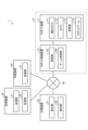
- Fig. 1 and Fig. 2 are diagrams each showing an example of the configuration of the visual inspection system 1 according to the present embodiment.
- the visual inspection system 1 according to the present embodiment is an example of an information processing system.
- the visual inspection system 1 includes a robot system 10, a working device 20, a storage device 30, and a learning device 40.
- the robot system 10, the working device 20, the storage device 30, and the learning device 40 are configured to be capable of communicating (transmitting and receiving) various types of information via a network 50.
- the robot system 10 includes a robot device 11 and a robot control device 12.
- the robot system 10 is a system that photographs an inspection object A1 (see FIG. 2) for inspection.
- the inspection object A1 is placed on an inspection table 13.
- the inspection object A1 is, for example, a circular metal part, but may be made of various materials and have various shapes.
- the robot device 11 has a polarized camera 111, a camera 112, a lighting unit 113, and a robot arm 114.
- the robot arm 114 has a pair of arms 114a, 114b (see FIG. 2).
- the polarized camera 111 is a camera that photographs (takes an image of) the inspection object A1 to obtain a polarized image.
- the polarized camera 111 is disposed above the inspection table 13 (see FIG. 2) and photographs the entire inspection object A1 placed on the placement surface, which is the upper surface of the inspection table 13, from a bird's-eye view.
- the captured polarized image contains information on the degree of polarization (DOP) and polarization direction (surface normal) of light, and it is possible to visualize each piece of information on the degree of polarization and polarization direction on a pixel-by-pixel basis.
- the polarized camera 111 functions as a second imaging unit.
- Camera 112 is an inspection image acquisition camera that photographs (takes an image of) inspection object A1 to obtain an inspection image.
- Camera 112 is attached to the tip of one arm 114a of robot arm 114 (see Figure 2).
- Camera 112 may be a normal RGB camera (color camera), or may be a non-visible light (UV, near-infrared, thermal, etc.) camera or a polarized camera depending on the inspection purpose.
- Camera 112 functions as a first imaging unit.
- the illumination unit 113 is an illuminator that shines light on the inspection target A1.
- the illumination unit 113 is attached to the tip of the other arm 114b of the robot arm 114 (see FIG. 2).
- the illumination unit 113 may include a light source such as an LED light bulb, a fluorescent lamp, or an incandescent light bulb, and may also include a light source that irradiates invisible light (UV, near-infrared, thermal, etc.) depending on the inspection purpose.
- the robot control device 12 has a control unit 121 and an arm control unit 122.
- the robot control device 12 functions as an information processing device.
- the control unit 121 controls, for example, the polarized camera 111, the camera 112, the lighting unit 113, etc.
- the control unit 121 may be any of a desktop PC (personal computer), a notebook PC, a tablet device, a smartphone, etc.
- the control unit 121 can access the working device 20, the storage device 30, the learning device 40, etc. via the network 50.
- the control unit 121 controls the polarization camera 111, the camera 112, the lighting unit 113, etc., based on the shooting conditions (image capture conditions), etc.
- the polarization camera 111 acquires a polarized image of the inspection object A1 under the control of the control unit 121.
- the camera 112 acquires an inspection image of the inspection object A1 under the control of the control unit 121.
- the polarization image and the inspection image are taken into the control unit 121 together with metadata such as shooting condition information, and are sent to the storage device 30 via the network 50. For example, when a series of shooting operations is completed, the multiple inspection images obtained by the series of shooting operations are sent to the storage device 30 together with the corresponding metadata.
- the arm control unit 122 controls the robot arm 114, i.e., the arms 114a and 114b (see FIG. 2).
- the arm control unit 122 controls the arms 114a and 114b within the ranges of motion of both the arms 114a and 114b, and can freely adjust the positions and orientations of the camera 112 and the lighting unit 113 independently.
- the arm control unit 122 sends control signals to the arms 114a and 114b based on the shooting conditions and the like, and controls the positions and angles of the joints of the arms 114a and 114b.
- the arm control unit 122 controls the trajectories of the arms 114a and 114b according to an operation program registered in the arm control unit 122.
- the operation program includes an image capture program that determines at what position and attitude on the trajectory the camera 112 will capture the inspection image, and at what position and attitude on the trajectory the illumination unit 113 will shine light on the inspection object A1 during the image capture. For example, it is possible to automatically capture 100 images (obtain 100 sets of image capture conditions) with one execution of the operation program.
- the operating device 20 has a display unit 21 and an operation unit 22.
- the operating device 20 may be, for example, any of a desktop PC (personal computer), a notebook PC, a tablet device, a smartphone, etc.
- the operating device 20 can access the robot system 10, the storage device 30, the learning device 40, etc. via a network 50.
- the operating device 20 functions as an information processing device.
- the display unit 21 displays various images. For example, the display unit 21 displays inspection images obtained by the camera 112 of the robot device 11 on a display screen.
- the display unit 21 may be, for example, a liquid crystal display, an organic EL (Electro-Luminescence) display, a head-mounted display, or the like. Multiple display units 21 may be provided depending on the application.
- the operation unit 22 accepts input operations from the assessor A2, who is the operator.
- the operation unit 22 may be any of a keyboard, a mouse, operation keys, a touch panel, etc.
- the assessor A2 performs various operations by touching the touch panel with a finger or a stylus.
- the operation unit 22 may also be a voice input device (for example, a microphone) that accepts input operations by voice from the assessor A2.
- the judge A2 is an inspector who operates the operation unit 22 to inspect the inspection object A1 while viewing the inspection image displayed on the display unit 21. For example, the judge A2 judges whether there are scratches on the surface of the inspection object A1, and operates the operation unit 22 to input the judgment result (inspection result).
- the input judgment result information (inspection result information) is sent to the storage device 30, for example, via the network 50, as metadata for the inspection image.
- step S64 the processing unit 31 of the storage device 30 sequentially sends the multiple inspection images in the selected image set for inspection skill assessment to the operation device 20.
- step S65 the display unit 21 of the operation device 20 displays the sent inspection images.
- each of the four image IDs #1 to #4 is an inspection image.
- an inspection item ID is #1 (scratch)
- the work ID is #1 (sample No.)
- the camera ID is #1 (model name + lens)
- the illumination ID is #1 (model name)
- the image capture condition ID is #1 (position/posture between devices).
- a group of inspection images extracted with a focus on the judge ID for example, a group of inspection images extracted with a focus on the expert judge ID #1
- a learning model of effective shooting conditions can be generated by machine learning the image group that combines the inspection image judged by the expert as having a scratch detected as the teacher data with other inspection images that were photographed in the same area but were judged by a non-expert judge A2 as having no scratch detected (OK).
- the judgment result has the same sign as the judgment difficulty, it is desirable to multiply the judgment result by the absolute value of the judgment difficulty and a coefficient of the inverse slope (for example, x1 if the judgment difficulty is -3, and x3 if the judgment difficulty is -1), and if the judgment result and the judgment difficulty have opposite signs, it is desirable to multiply the judgment result by the absolute value of the judgment difficulty and an even larger coefficient of the quasi-slope (for example, x4 to x6).
- a coefficient of the inverse slope for example, x1 if the judgment difficulty is -3, and x3 if the judgment difficulty is -1
- the certainty of evaluator ID #2 is 3/4 the first time, 4/4 the second time, and 4/4 the third time.
- the certainty of evaluator ID #3 is 2/4 the first time, 2/4 the second time, and 2/4 the third time.
- the certainty of evaluator ID #4 is 1/4 the first time, 3/4 the second time, and 2/4 the third time.
- the variation is indicated by a change over time in the frequency of occurrence of -1/+1 (for example, a trend in amplitude or a trend in bias).
- Amplitude trend (count value of +1) weighted in (C) above + (count value of -1)
- Bias tendency (count value of +1) weighted in (C) above - (count value of -1)
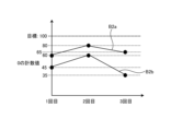
- time required is shown by the time from the end of the inspection of the previous image to the end of the inspection of the next image, as shown in Fig. 14 (see graph B4).
- the average value and standard deviation of this time can be calculated by the following formulas (2) and (3).
- Continuity is shown by the correlation (change over time) between the timestamp (t) of the image and the accuracy (%), as shown in Fig. 15 (see graph B5). This correlation is calculated by the following formula (4).
- (F) Training Menu It is possible to design an individual training menu for judge A2 according to the skill level of judge A2, using a group of images extracted with a focus on the image ID described above.
- Fig. 16 is a diagram for explaining an example of systematization of the skill level of assessor A2.
- indexing of judgment skills is shown as the skill level of assessor A2
- a spider chart (radar chart) C1 is shown as a specific example of evaluation axes and systematization.
- Judgment skills include accuracy (certainty), persistence (concentration), stability, proficiency, endurance (duration), and quick decision-making (time required). These judgment skills are obtained as shown in (D) and (E) above.
- Such a spider chart C1 is displayed, for example, on the display unit 21 of the work device 20. This allows judge A2 to understand his or her own judgment skills.
- the spider chart C1 may be displayed by another display device as necessary. For example, other experts or managers may be able to check the judgment skills of the judge A2 by looking at the spider chart C1 displayed by the display device.
- the judgment skills of each judge A2 may be recorded in the storage device 30 or another storage device. Furthermore, the judgment skills of the judge A2 may be shown by graphs such as pie charts or bar graphs, or other figures, in addition to the spider chart C1.
- Fig. 17 is a diagram showing a configuration example of the appearance inspection system 1 according to a modified example of the present embodiment.
- the appearance inspection system 1 according to the modified example of the present embodiment is an example of an information processing system.
- the judgment skill according to this embodiment is not a specialized skill specialized for visual inspection, but can be generalized as a skill for visually checking an image and extracting and judging a context according to the purpose, and can be diverted to other applications.
- the modified example according to this embodiment as a specific example, an application example to a remote operation task of a harvesting robot deployed in a farm that harvests tomatoes and other vegetables is shown.
- the visual inspection system 1 functions as an agricultural harvesting system.
- the appearance inspection system 1 includes a robot device 60 in addition to the above-mentioned operating device 20, storage device 30, and learning device 40.
- the robot device 60 has a body 61, wheels 62, a camera 63, and a gripping unit 64.
- the robot device 60 functions as a harvesting robot.
- the robot device 60 may also have a lighting unit 113, as in the above-described embodiment.
- the machine body 61 is the main body of the robot device 60.
- the wheels 62 are rotatably mounted on the underside of the machine body 61, and are configured to allow the machine body 61 to move.
- the camera 63 corresponds to the camera 112 described above. This camera 63 captures an image of a desired area including, for example, the harvest object A3.
- the harvest object A3 may be, for example, a vegetable such as a tomato or cucumber, or may be a fruit other than a vegetable.
- the harvest object A3 corresponds to the inspection object A1 described above.
- the camera 63 functions as a first imaging unit.
- the gripping unit 64 has a hand 641 and a robot arm 642.
- the hand 641 is attached to the tip of the robot arm 642 and is configured to be able to grip the harvest target A3.
- the robot arm 642 is configured to be able to move the hand 641 located at its tip to the desired position.
- the aforementioned machine body 61 incorporates a control device 611, an image sensor 612, a unit drive unit 613, and a machine body drive unit 614.
- the control device 611 corresponds to the aforementioned robot control device 12.
- the control device 611 controls the unit drive unit 613 and the machine body drive unit 614.
- the image sensor 612 is part of the camera 63, and is, for example, an image sensor.
- the unit drive unit 613 drives the grip unit 64.
- the machine body drive unit 614 drives the machine body 61, i.e., the wheels 62 provided on the machine body 61.
- the working device 20 includes a calculation device 23 in addition to the display unit 21 and operation unit 22 described above.
- the display unit 21 and operation unit 22 are connected to the operation unit 23.
- the assessor A2 can, for example, operate the operation unit 22 as necessary to remotely control the robot device 60.
- the assessor A2 can operate the operation unit 22 to change the imaging conditions, such as the zoom of the camera 63, and can also operate the gripping unit 64 (remote control).
- the robot device 60 travels, for example, between the furrows and stops in front of each plant.
- the camera 63 takes, for example, a picture of the entire plant.
- the captured image is transmitted to the computing device 23 via the network 50 and displayed on the display unit 21. In this way, the inspection image is provided to the assessor A2, who is an operator.
- the assessor A2 identifies a mature harvest target A3 (e.g., a tomato) from the inspection image displayed on the display unit 21, and uses the operation unit 22 to specify the mature harvest target A3 on the image and give harvest instructions to the robot device 60.
- the harvest instructions are transmitted to the control device 611 of the robot device 60 via the network 50.
- the control device 611 controls the unit drive unit 613 to drive the gripping unit 64, i.e., the robot arm 642 and hand 641, to harvest the harvest target A3.
- the assessor A2 repeats the harvest instruction using the operation unit 22.
- the assessor A2 inputs an end instruction using the operation unit 22.
- the end instruction is also transmitted to the control device 611 of the robot device 60 via the network 50.
- the control device 611 controls the machine drive unit 614 to drive the wheels 62 and move the robot device 60 to the next plant.
- the captured inspection image is assigned, for example, a unique ID, a timestamp of the date and time of shooting, and if the assessor A2 judges the fruit to be ripe, the coordinate information of the harvest object A3 for which harvesting was instructed, a timestamp of the harvest date and time (inspection date and time), and the assessor ID are assigned as metadata.
- the inspection image with the metadata assigned is recorded in the storage device 30.
- the learning device 40 reads out and analyzes these inspection images, and records the learning results (learning model) in the storage device 30.
- the speed at which evaluator A2 makes decisions affects the overall work time, and his or her endurance affects the amount of work (harvest yield). Accuracy and persistence affect the quality of the harvested crop. In other words, it is possible to recommend the task of remotely operating an agricultural harvesting robot to evaluator A2 who has a high score on these skill evaluation indices in visual inspection.
- inspection standards are usually necessary to verify the effectiveness of the shooting conditions, and in order to construct such inspection standards, for example, a suitable number of defective samples is required, and a process is required to efficiently create the inspection standards using the knowledge of inspectors (experienced persons) who have empirically accurate judgment standards. Furthermore, as the number of experienced inspectors is on the decline, it is also important to effectively pass on judgment standards in sensory inspections, thereby training and increasing the number of inspectors who can engage in such inspections.
- parameters that define the shooting conditions include not only the individual positions and orientations of the camera 112 and the lighting unit 113, but also, for example, the surface shape of the object to be inspected A1.
- the inspection image is added with a set J1 of the inspection item ID (inspection item information), the work ID (work information), the camera ID (camera information), and the lighting ID (lighting information), a set J2 of the image ID (image information), the shooting condition ID (shooting condition information), and the timestamp (shooting date and time information), and a set J3 of the judge ID (judge information), the judgment result (judgment result information), the designated coordinates (designated coordinate information), and the timestamp (judgment date and time information) as metadata (see FIG. 6). That is, the inspection image is recorded by the storage device 30 together with the metadata.
- the recording of the inspection image and the metadata is performed for each shooting timing, that is, for each inspection image.
- information including, for example, the shooting condition information, the identification information of the judge A2, and the judgment result information is stored. Therefore, it is possible to efficiently obtain appropriate information for creating the inspection standard, and therefore the inspection standard can be efficiently created.
- the imaging condition information for the imaging condition ID also includes work information, i.e., surface normal information (see FIG. 5), so it is possible to obtain not only the individual position and orientation information of the camera 112 and the lighting unit 113, but also the surface shape of the inspection target A1.
- work information i.e., surface normal information (see FIG. 5)
- the photographing of the inspection object A1 by the robot device 11 and the image inspection by the assessor A2 can be separated in time, so the assessor A2 can perform the inspection work remotely regardless of location. Furthermore, by learning the relationship between the judgment result information by the experienced assessor A2 and the metadata, it is possible to evaluate the effectiveness of the shooting conditions based on highly reliable teacher data. Furthermore, by having an inexperienced assessor A2 make a judgment on the same group of inspection images as the judgment of the experienced assessor A2, and evaluating the difference between the judgment results of the assessor A2 and the judgment results of the experienced assessor A2, it is possible to specifically recognize the discrepancy in judgment skills.
- a more effective educational tool can be provided by having an inexperienced judge A2 and an experienced judge A2 simultaneously access the same test image from different locations via network 50 and share each other's judgment results in real time. For example, if the judgment skills of the inexperienced judge A2 improve under the guidance of the experienced judge A2, it is possible to index the results as the educational and instruction skills of the experienced judge A2.
- the information can be kept secret even during remote judgment work by changing the order of the partial images presented to the judge A2 or by providing only the information necessary for the inspection purpose from the information of the polarization camera 111 (e.g., the degree of polarization, polarization direction, reflection components, etc.).
- the appearance inspection system 1 includes a first imaging unit (e.g., the camera 112 or the camera 63) that photographs the inspection object A1 to obtain an image, and a processing unit 31 that generates information including an image obtained by the first imaging unit (e.g., an inspection image), shooting condition information when the inspection object A1 was photographed (e.g., position information and posture information of the camera 112 or the camera 63), identification information of the inspector who inspected the inspection object A1 based on the image (e.g., the judge ID of the judge A2), and inspection result information of the inspection object A1 (e.g., judgment result information on the presence or absence of scratches).
- information including the shooting condition information, the inspector's identification information, and the inspection result information is generated for each image. Therefore, it is possible to obtain appropriate information for creating the inspection standard, so that the inspection standard can be created efficiently.
- the processing unit 31 may also add shooting condition information to the image, and add the examiner's identification information and the test result information to the image to which the shooting condition information has been added. This makes it possible to reliably obtain appropriate information for creating the test criteria.
- the appearance inspection system 1 further includes a second imaging unit (e.g., a polarized camera 111) that captures an image of the inspection object A1 to obtain surface normal information, and the imaging condition information may include the surface normal information. This makes it possible to obtain the surface shape of the inspection object A1.
- a second imaging unit e.g., a polarized camera 111
- the first imaging unit may also image a partial area A1a of the inspection object A1, and the imaging condition information may include position information of the partial area A1a and surface normal information of the partial area A1a. This makes it possible to obtain not only the position information of the partial area A1a of the inspection object A1, but also the surface shape of the partial area A1a.
- the imaging condition information may also include position information and orientation information of the first imaging unit when the inspection object A1 is imaged. This generates various types of information, making it possible to obtain appropriate information for creating inspection standards.
- the appearance inspection system 1 may further include an illumination unit 113 that shines light on the inspection object A1, and the photographing condition information may include position information and posture information of the illumination unit 113 when photographing the inspection object A1. This generates such information, making it possible to obtain appropriate information for creating inspection standards.
- the above-mentioned information may also include shooting condition information, inspector identification information, and inspection result information for each of the multiple images. This generates such information, making it possible to obtain appropriate information for creating inspection standards.
- the above information may also include inspector identification information and inspection result information for each of multiple inspectors. This generates the information, making it possible to obtain appropriate information for creating inspection standards.
- the inspection result information may also include information on the presence or absence of scratches. This generates the judgment information, making it possible to obtain appropriate information for creating inspection standards.
- the inspection result information may also include specified coordinate information indicating the location of the scratch. This generates the specified coordinate information, making it possible to obtain appropriate information for creating inspection criteria.
- the processing unit 31 may also compare the inspector's inspection result information for the image with the expert's inspection result information for the image, and certify that the inspector is an expert based on the comparison result. This makes it possible to realize an expert certification process that certifies an expert.
- HDD 1400 is a computer-readable recording medium that non-temporarily records programs executed by CPU 1100 and data used by such programs. Specifically, HDD 1400 is a recording medium that records program data 1450.
- the present technology can also be configured as follows.
- An information processing system comprising: (2) The processing unit includes: adding the photographing condition information to the image; adding the identification information of the examiner and the examination result information to the image to which the imaging condition information has been added; The information processing system according to (1) above. (3) A second imaging unit is further provided for imaging the inspection object to obtain surface normal information, The photographing condition information includes the surface normal information.
- the information includes the identification information and the test result information of the inspectors for each of the multiple inspectors.
- the information processing system according to any one of (1) to (7).
- the inspection result information includes information on the presence or absence of scratches.
- the inspection result information includes designated coordinate information indicating the position of the scratch.
- the processing unit compares the inspection result information of the inspector for the image with the inspection result information of the expert for the image, and certifies that the inspector is an expert based on a comparison result.
- the information processing system according to any one of (1) to (10).
- (12) The processing unit determines a skill level of the inspector using the inspection result information of the inspector for the image.
Landscapes
- Physics & Mathematics (AREA)
- Engineering & Computer Science (AREA)
- General Physics & Mathematics (AREA)
- General Health & Medical Sciences (AREA)
- Analytical Chemistry (AREA)
- Biochemistry (AREA)
- Chemical & Material Sciences (AREA)
- Life Sciences & Earth Sciences (AREA)
- Immunology (AREA)
- Pathology (AREA)
- Health & Medical Sciences (AREA)
- Computer Vision & Pattern Recognition (AREA)
- Theoretical Computer Science (AREA)
- Investigating Materials By The Use Of Optical Means Adapted For Particular Applications (AREA)
Priority Applications (1)
| Application Number | Priority Date | Filing Date | Title |
|---|---|---|---|
| JP2025535756A JPWO2025023104A1 (https=) | 2023-07-27 | 2024-07-17 |
Applications Claiming Priority (2)
| Application Number | Priority Date | Filing Date | Title |
|---|---|---|---|
| JP2023-122573 | 2023-07-27 | ||
| JP2023122573 | 2023-07-27 |
Publications (1)
| Publication Number | Publication Date |
|---|---|
| WO2025023104A1 true WO2025023104A1 (ja) | 2025-01-30 |
Family
ID=94374414
Family Applications (1)
| Application Number | Title | Priority Date | Filing Date |
|---|---|---|---|
| PCT/JP2024/025569 Pending WO2025023104A1 (ja) | 2023-07-27 | 2024-07-17 | 情報処理システム、情報処理装置及び情報生成方法 |
Country Status (2)
| Country | Link |
|---|---|
| JP (1) | JPWO2025023104A1 (https=) |
| WO (1) | WO2025023104A1 (https=) |
Citations (4)
| Publication number | Priority date | Publication date | Assignee | Title |
|---|---|---|---|---|
| JPH06160190A (ja) * | 1992-11-24 | 1994-06-07 | Nippon Telegr & Teleph Corp <Ntt> | 色調検査判定評価方法 |
| JP2015206626A (ja) * | 2014-04-18 | 2015-11-19 | 大日本印刷株式会社 | 同一形状の検査対象部位の検査装置および方法 |
| JP2017101934A (ja) * | 2015-11-30 | 2017-06-08 | キヤノン株式会社 | 処理装置、処理システム、撮像装置、処理方法、処理プログラムおよび記録媒体 |
| JP2022064334A (ja) * | 2020-10-14 | 2022-04-26 | アスカカンパニー株式会社 | 異物発生原因推定システム及び異物発生原因推定方法 |
-
2024
- 2024-07-17 WO PCT/JP2024/025569 patent/WO2025023104A1/ja active Pending
- 2024-07-17 JP JP2025535756A patent/JPWO2025023104A1/ja active Pending
Patent Citations (4)
| Publication number | Priority date | Publication date | Assignee | Title |
|---|---|---|---|---|
| JPH06160190A (ja) * | 1992-11-24 | 1994-06-07 | Nippon Telegr & Teleph Corp <Ntt> | 色調検査判定評価方法 |
| JP2015206626A (ja) * | 2014-04-18 | 2015-11-19 | 大日本印刷株式会社 | 同一形状の検査対象部位の検査装置および方法 |
| JP2017101934A (ja) * | 2015-11-30 | 2017-06-08 | キヤノン株式会社 | 処理装置、処理システム、撮像装置、処理方法、処理プログラムおよび記録媒体 |
| JP2022064334A (ja) * | 2020-10-14 | 2022-04-26 | アスカカンパニー株式会社 | 異物発生原因推定システム及び異物発生原因推定方法 |
Also Published As
| Publication number | Publication date |
|---|---|
| JPWO2025023104A1 (https=) | 2025-01-30 |
Similar Documents
| Publication | Publication Date | Title |
|---|---|---|
| Ghadiyaram et al. | Massive online crowdsourced study of subjective and objective picture quality | |
| Giuffrida et al. | Citizen crowds and experts: observer variability in image-based plant phenotyping | |
| JP2020077326A (ja) | 撮影方法及び撮影装置 | |
| US11947345B2 (en) | System and method for intelligently monitoring a production line | |
| CN109584227A (zh) | 一种基于深度学习目标检测算法的焊点质量检测方法及其实现系统 | |
| TWI747686B (zh) | 缺陷檢測方法及檢測裝置 | |
| CN109543679A (zh) | 一种基于深度卷积神经网络的死鱼识别方法及预警系统 | |
| Dolata et al. | Instance segmentation of root crops and simulation-based learning to estimate their physical dimensions for on-line machine vision yield monitoring | |
| RU2669527C2 (ru) | Сеть интеллектуальных машин | |
| JP6288249B2 (ja) | 目視検査支援装置、目視検査支援方法及び目視検査支援プログラム | |
| KR101900200B1 (ko) | 딥러닝 기반 결핵 검사 방법 | |
| CN117058752A (zh) | 一种基于改进YOLOv7的学生课堂行为检测方法 | |
| US12175779B2 (en) | Information processing device and information processing method to evaluate a person in charge of labeling | |
| CN119168425B (zh) | 牧场养殖场景下围产奶牛采食量预测方法及系统 | |
| Ibrahim | Real-time automatic inspection system for the classification of PCB flux defects | |
| CN107609334A (zh) | 一种现场观众反应分析系统及方法 | |
| Valiente et al. | Non-destructive image processing analysis for defect identification and maturity detection on avocado fruit | |
| Carlson et al. | Automated high-frequency observations of physical activity using computer vision | |
| CN110543828A (zh) | 基于可穿戴设备和多模态智能分析的学生注意力分析系统 | |
| JP2019075078A (ja) | 工事現場画像判定装置及び工事現場画像判定プログラム | |
| WO2025023104A1 (ja) | 情報処理システム、情報処理装置及び情報生成方法 | |
| JP7735008B2 (ja) | 情報処理装置 | |
| WO2019073615A1 (ja) | 工事現場画像判定装置及び工事現場画像判定プログラム | |
| Han et al. | What Images are More Memorable to Machines? | |
| Sugiyama et al. | Artificial intelligence-integrated video analysis of vessel area changes and instrument motion for microsurgical skill assessment |
Legal Events
| Date | Code | Title | Description |
|---|---|---|---|
| 121 | Ep: the epo has been informed by wipo that ep was designated in this application |
Ref document number: 24845484 Country of ref document: EP Kind code of ref document: A1 |
|
| ENP | Entry into the national phase |
Ref document number: 2025535756 Country of ref document: JP Kind code of ref document: A |
|
| WWE | Wipo information: entry into national phase |
Ref document number: 2025535756 Country of ref document: JP |
|
| NENP | Non-entry into the national phase |
Ref country code: DE |