WO2025022761A1 - 電動弁制御装置および電動弁装置、ならびに、電動弁の状態判定方法 - Google Patents
電動弁制御装置および電動弁装置、ならびに、電動弁の状態判定方法 Download PDFInfo
- Publication number
- WO2025022761A1 WO2025022761A1 PCT/JP2024/017644 JP2024017644W WO2025022761A1 WO 2025022761 A1 WO2025022761 A1 WO 2025022761A1 JP 2024017644 W JP2024017644 W JP 2024017644W WO 2025022761 A1 WO2025022761 A1 WO 2025022761A1
- Authority
- WO
- WIPO (PCT)
- Prior art keywords
- motor
- pulse
- rotor
- operated valve
- input
- Prior art date
- Legal status (The legal status is an assumption and is not a legal conclusion. Google has not performed a legal analysis and makes no representation as to the accuracy of the status listed.)
- Pending
Links
Images















Classifications
-
- F—MECHANICAL ENGINEERING; LIGHTING; HEATING; WEAPONS; BLASTING
- F16—ENGINEERING ELEMENTS AND UNITS; GENERAL MEASURES FOR PRODUCING AND MAINTAINING EFFECTIVE FUNCTIONING OF MACHINES OR INSTALLATIONS; THERMAL INSULATION IN GENERAL
- F16K—VALVES; TAPS; COCKS; ACTUATING-FLOATS; DEVICES FOR VENTING OR AERATING
- F16K31/00—Actuating devices; Operating means; Releasing devices
- F16K31/02—Actuating devices; Operating means; Releasing devices electric; magnetic
- F16K31/04—Actuating devices; Operating means; Releasing devices electric; magnetic using a motor
-
- H—ELECTRICITY
- H02—GENERATION; CONVERSION OR DISTRIBUTION OF ELECTRIC POWER
- H02P—CONTROL OR REGULATION OF ELECTRIC MOTORS, ELECTRIC GENERATORS OR DYNAMO-ELECTRIC CONVERTERS; CONTROLLING TRANSFORMERS, REACTORS OR CHOKE COILS
- H02P8/00—Arrangements for controlling dynamo-electric motors rotating step by step
- H02P8/34—Monitoring operation
Definitions
- the present invention relates to an electric valve control device, an electric valve device having an electric valve control device, and a method for determining the state of an electric valve.
- Patent Document 1 discloses an example of a conventional motor-operated valve.
- the motor-operated valve is incorporated, for example, in the refrigeration cycle system of an air conditioner.
- the motor-operated valve has a valve body, a valve element, and a stepping motor for moving the valve element.
- the stepping motor has a rotor and a stator.
- the stator has a coil.
- the valve element moves in response to the rotation of the rotor.
- a movable stopper that rotates with the rotor abuts against a fixed stopper fixed to the valve body, restricting the rotation of the rotor in a first direction.
- the motor-operated valve is controlled by an electric valve control device.
- the motor-operated valve control device inputs pulses to the stepping motor to rotate the rotor in a first direction and position the rotor at a reference position.
- the number of pulses input to the stepping motor is a number sufficient for the movable stopper to abut against the fixed stopper (hereinafter referred to as the "initialization number").
- the waveform of the voltage (voltage electromagnetically induced in the stator) generated by the rotation of the rotor during the initialization operation differs before and after the rotation of the rotor is restricted.
- the motor-operated valve control device disclosed in Patent Document 2 acquires the voltage generated in the stator by the rotation of the rotor, and determines whether the rotation of the rotor in the first direction is restricted based on the degree of difference between the voltage waveform and a reference voltage waveform.
- the motor-operated valve control device determines that the rotation of the rotor in the first direction is restricted, it stops the rotation of the rotor. In this way, the motor-operated valve control device stops the rotation of the rotor immediately after the rotor is positioned at the reference position, preventing noise from being generated for a long period of time.
- the stator has an A-phase stator and a B-phase stator.
- the voltage generated in the A-phase stator includes a voltage component generated by the drive current and a voltage component generated by the rotation of the rotor.
- the voltage generated in the B-phase stator also includes a voltage component generated by the drive current and a voltage component generated by the rotation of the rotor.
- the frequency and amplitude of the voltage component generated by the drive current are relatively high, and the voltage component generated by the rotation of the rotor is hidden by the voltage component generated by the drive current.
- the motor-operated valve control device of Patent Document 2 therefore determines whether or not rotation of the rotor in the first direction is restricted when a drive current is supplied to only one of the A-phase stator and the B-phase stator, based on the voltage generated in the other stator to which no drive current is supplied.
- the motor-operated valve control device cannot determine whether or not rotation of the rotor in the first direction is restricted when drive current is supplied to both the A-phase stator and the B-phase stator. Therefore, the motor-operated valve control device may not be able to determine the timing at which rotation of the rotor in the first direction is actually restricted.
- the processing device determines whether the motor-operated valve is in the rotation restriction state based on the degree of difference between the waveform of the voltage component and a reference waveform of the voltage component.
- a motor driver is connected to the coil, and when multiple pulses having consecutive numbers are input to the motor driver in a repeated order, the motor driver supplies the drive current corresponding to the multiple pulses to the coil to rotate the rotor, and the processing device starts inputting the multiple pulses to the motor driver, acquires the voltage component when the drive current corresponding to the pulse input to the motor driver (hereinafter referred to as the "target pulse") is supplied to the coil, and uses the voltage component to determine whether the motor-operated valve is in the rotation restriction state, and when it is determined that the motor-operated valve is in the rotation restriction state, stops inputting the multiple pulses before inputting the next pulse of the target pulse.
- the target pulse the voltage component when the drive current corresponding to the pulse input to the motor driver
- a motor driver is connected to the coil, and when multiple pulses having consecutive numbers are input to the motor driver in a repeated order, the motor driver supplies the drive current corresponding to the multiple pulses to the coil to rotate the rotor, and the processing device starts inputting the multiple pulses to the motor driver, acquires the voltage component when the drive current corresponding to the pulse input to the motor driver (hereinafter referred to as the "target pulse") is supplied to the coil, and determines whether the motor-operated valve is in the rotation restriction state using the voltage component during the input period of the next pulse of the target pulse, and when it is determined that the motor-operated valve is in the rotation restriction state, inputs a pulse having the same number as the target pulse to the motor driver following the next pulse of the target pulse, and stops inputting the multiple pulses.
- the target pulse the voltage component when the drive current corresponding to the pulse input to the motor driver
- a motor driver is connected to the coil, and when multiple pulses having consecutive numbers are input to the motor driver in a repeated order, the motor driver supplies the driving current corresponding to the multiple pulses to the coil to rotate the rotor, and the processing device starts inputting the multiple pulses to the motor driver, acquires the voltage component when the driving current corresponding to the pulse input to the motor driver (hereinafter referred to as the "target pulse") is supplied to the coil, and determines whether the motor-operated valve is in the rotation restriction state using the voltage component during the input period of the next pulse of the target pulse, and when it is determined that the motor-operated valve is in the rotation restriction state, inputs the multiple pulses to the motor driver in order until a pulse having the same number as the target pulse is input to the motor driver following the next pulse of the target pulse, and stops inputting the multiple pulses.
- target pulse the driving current corresponding to the pulse input to the motor driver
- the cutoff frequency is set based on the pulse width modulation frequency.
- another aspect of the present invention is an electric valve device that includes the electric valve and the electric valve control device.
- a stepping motor has a rotor and a stator, and a drive current for rotating the rotor, which is controlled by a pulse width modulation method, is supplied to the coil of the stator. Then, a voltage component of a frequency lower than the cutoff frequency in the voltage generated in the coil is used to determine whether the motor-operated valve is in a rotation restricted state in which the rotation of the rotor is restricted. In this way, it is possible to remove the relatively high-frequency voltage component generated by the drive current from the voltage generated in the coil, and it is possible to prevent the voltage component generated by the rotation of the rotor from being hidden by the voltage component generated by the drive current.
- FIG. 1 is a block diagram of an air conditioning system having an electric valve device.
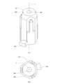
- FIG. FIG. 2 is a diagram showing a valve stem holder of the motor-operated valve device.
- FIG. 4 is a side view of a guide bush of the motor-operated valve device.
- 4A and 4B are diagrams showing a stopper member of the motor-operated valve device.
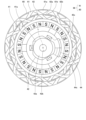
- 2 is a plan view of a valve stem holder, a stopper member, a rotor and a stator of the motor-operated valve device.
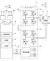
- FIG. FIG. 2 is a diagram showing a computer, a motor driver, a low-pass filter, and a stepping motor included in an electric valve control device of the electric valve device.
- FIG. 1A and 1B are diagrams illustrating an example of the relationship between step signals and direction signals input to a motor driver and pulses input to a stepping motor.
- 11 is a diagram showing an example of a correspondence relationship between a pulse and an A-phase current target value and a B-phase current target value.
- FIG. 4A and 4B are diagrams illustrating examples of waveforms of A-phase current and B-phase current.
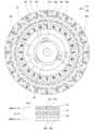
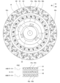
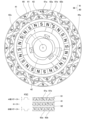
- 4 is a diagram showing a schematic diagram of the positional relationship between the magnetic poles of the rotor and the pole teeth of the stator (when pulse P[1] is input).
- FIG. 4 is a diagram showing a schematic diagram of the positional relationship between the magnetic poles of the rotor and the pole teeth of the stator (when pulse P[2] is input).
- FIG. 1 is a diagram showing a schematic diagram of the positional relationship between the magnetic poles of the rotor and the pole teeth of the stator (when pulse P[3] is input).
- FIG. 1 is a diagram showing a schematic diagram of the positional relationship between the magnetic poles of the rotor and the pole teeth of the stator (when pulse P[4] is input).
- FIG. 1 is a diagram showing a schematic diagram of the positional relationship between the magnetic poles of the rotor and the pole teeth of the stator (when pulse P[5] is input).
- FIG. 1 is a diagram showing a schematic diagram of the positional relationship between the magnetic poles of the rotor and the pole teeth of the stator (when pulse P[6] is input).
- FIG. 1 is a diagram showing a schematic diagram of the positional relationship between the magnetic poles of the rotor and the pole teeth of the stator (when pulse P[6] is input).
- FIG. 1 is a diagram showing a schematic diagram of the positional relationship between the magnetic poles of the rotor and the pole teeth of the stator (when pulse P[7] is input).
- FIG. 1 is a diagram showing a schematic diagram of the positional relationship between the magnetic poles of the rotor and the pole teeth of the stator (when pulse P[8] is input).
- FIG. 4 is a diagram showing an example of a waveform of a voltage generated in a coil of a stator.
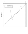
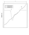
- FIG. 20 is a diagram showing an example of a waveform of a voltage component having a frequency lower than the cutoff frequency in the voltage shown in FIG. 19 .
- FIG. 13 is a diagram showing an example of a waveform of a voltage component having a frequency lower than the cutoff frequency in the voltage generated in the stator coil (a state in which the rotor is allowed to rotate).
- FIG. 13 is a diagram showing an example of a waveform of a voltage component having a frequency lower than the cutoff frequency in the voltage generated in the stator coil (a state in which rotation of the rotor is restricted).
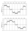
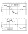
- FIG. 4 is a diagram showing an example of a rotation angle of a rotor.
- 10A and 10B are diagrams comparing waveforms of voltage components at frequencies lower than the cutoff frequency in the voltage generated in the stator coil.
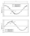
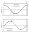
- FIG. 11 is a diagram comparing waveforms of voltage components at frequencies lower than the cutoff frequency in the voltage generated in the stator coil (microstep method 1).
- FIG. 11 is a diagram showing an example of the rotation angle of the rotor (microstep method 2).
- FIG. 11 is a diagram comparing waveforms of voltage components at frequencies lower than the cutoff frequency in the voltage generated in the stator coil (microstep method 2).
- FIG. 1 is a block diagram of an air conditioning system having an electric valve device.
- FIG. 2 is a cross-sectional view of the electric valve device.
- FIG. 3 is a diagram showing a valve stem holder of the electric valve device.
- FIG. 3A is an oblique view of the valve stem holder, and
- FIG. 3B is a plan view of the valve stem holder.
- FIG. 4 is a side view of a guide bush of the electric valve device.
- FIG. 5 is a diagram showing a stopper member of the electric valve device.
- FIG. 5A is an oblique view of the stopper member
- FIG. 5B is a plan view of the stopper member.
- FIG. 6 is a plan view of the valve stem holder, stopper member, rotor, and stator of the electric valve device. In FIG. 6, the magnetic poles of the rotor and the stator are shown typically.
- FIG. 7 is a diagram showing a computer, a motor driver, a low-pass filter, and a stepping motor possessed by an electric valve control device of the electric valve device.
- FIG. 8 is a diagram showing an example of the relationship between the step signal and the direction signal input to the motor driver, and the pulse input to the stepping motor (motor driver).
- FIG. 9 is a diagram showing an example of the correspondence between the pulse, the A-phase current target value, and the B-phase current target value.
- FIG. 10 shows examples of A-phase current waveforms and B-phase current waveforms.
- FIG. 11 to FIG. 18 are schematic diagrams showing the positional relationship between the rotor magnetic poles and the stator pole teeth.
- FIG. 19 is a diagram showing an example of the waveform of the voltage generated in the stator coil.
- FIG. 20 is a diagram showing an example of the waveform of the voltage component of the frequency lower than the cutoff frequency, which has passed through a low-pass filter, for the voltage shown in FIG. 19.
- FIGS. 21 and 22 are diagrams showing examples of the waveform of the voltage component of the frequency lower than the cutoff frequency in the voltage generated in the stator coil.
- FIG. 21 shows the waveform of the voltage component in a state in which the rotor rotation is permitted
- FIG. 22 shows the waveform of the voltage component in a state in which the rotor rotation is restricted.
- FIG. 23 is a diagram showing an example of the rotation angle of the rotor.
- FIG. 21 shows the waveform of the voltage component in a state in which the rotor rotation is permitted
- FIG. 22 shows the waveform of the voltage component in a state in which the rotor rotation is restricted.
- FIG. 23 is a diagram showing an example of
- FIG. 23 shows the change in the rotation angle of the rotor with respect to the input of a pulse.
- FIG. 24 is a diagram comparing the waveform of the voltage component of the frequency lower than the cutoff frequency in the voltage generated in the stator coil.
- FIG. 24 is a diagram comparing the waveform of the voltage component in a state in which the rotor rotation is permitted and the waveform of the voltage component in a state in which the rotor rotation is restricted.
- FIG. 25 is a diagram showing an example of a data table relating to the reference waveform of the voltage component of the frequency lower than the cutoff frequency in the voltage generated in the stator coil.
- FIG. 26 is a diagram showing an example of the waveform of a voltage component at a frequency lower than the cutoff frequency in the voltage generated in the stator coil, and a reference waveform of the voltage component.
- FIG. 27 and FIG. 28 are flowcharts showing examples of the operation of the motor-operated valve control device.
- FIG. 27 shows operation example 1
- FIG. 28 shows operation examples 2 and 3.
- the horizontal axis is time
- the vertical axis is voltage
- the horizontal axis is time
- the vertical axis is rotation angle.
- the motor-operated valve device 1 is used, for example, as a flow control valve that controls the flow rate of a refrigerant fluid in an air conditioning system.
- FIG. 1 shows an example of an air conditioning system 100 mounted on a vehicle.
- the air conditioning system 100 has a compressor 101, a condenser 102, an electric valve device 1 (electric valve 5), and an evaporator 103, which are connected in sequence via piping 105.
- the electric valve device 1 is an expansion valve.
- the air conditioning system 100 has an air conditioning control device 110.
- the air conditioning control device 110 is connected to the electric valve device 1 (electric valve control device 70) so that it can communicate with them.
- the air conditioning control device 110 uses the electric valve device 1 to control the flow rate of refrigerant flowing through the piping 105.
- the motor-operated valve device 1 has a motor-operated valve 5 and a motor-operated valve control device 70.
- the valve body 10 has a main body member 11 and a connecting member 13.
- the main body member 11 has a cylindrical shape.
- the main body member 11 has a valve chamber 14, a valve port 17, and a valve seat 18.
- a first conduit 15 and a second conduit 16 are joined to the main body member 11.
- the first conduit 15 is arranged along a direction perpendicular to the axis L (left-right direction in FIG. 2) and is connected to the valve chamber 14.
- the second conduit 16 is arranged along the axis L direction (up-down direction in FIG. 2) and is connected to the valve chamber 14 via the valve port 17.
- the valve port 17 is surrounded by a ring-shaped valve seat 18 in the valve chamber 14.
- the main body member 11 has a circular fitting hole 11a.
- the valve body 30 has a first shaft portion 31, a second shaft portion 32, and a valve portion 33.
- the first shaft portion 31 has a cylindrical shape.
- the second shaft portion 32 has a cylindrical shape.
- the diameter of the second shaft portion 32 is smaller than the diameter of the first shaft portion 31.
- the second shaft portion 32 is coaxially connected to the upper end portion of the first shaft portion 31.
- the valve body 30 has a step portion 34 which is a circular annular plane facing upward.
- the step portion 34 is disposed at the connection portion between the first shaft portion 31 and the second shaft portion 32.
- the valve portion 33 has a generally conical shape whose diameter decreases from the top to the bottom.
- the valve portion 33 is coaxially connected to the lower end portion of the first shaft portion 31.
- the valve portion 33 is disposed in the valve port 17.
- the drive mechanism 40 moves the valve body 30 in the vertical direction (axis L direction). The movement of the valve body 30 opens and closes the valve port 17.
- the drive mechanism 40 has a rotor 41, a valve shaft holder 42, a guide bush 43, a stopper member 44, and a fixing device 45.
- the rotor 41 has a cylindrical shape.
- the outer diameter of the rotor 41 is slightly smaller than the inner diameter of the can 20.
- the rotor 41 is disposed inside the can 20.
- the rotor 41 is rotatable relative to the valve body 10.
- the rotor 41 has multiple north poles and multiple south poles.
- the multiple north poles and multiple south poles are disposed on the outer circumferential surface of the rotor 41.
- the multiple north poles and multiple south poles extend in the vertical direction.
- the multiple north poles and multiple south poles are disposed alternately at equal angular intervals in the circumferential direction.
- the rotor 41 has, for example, 12 north poles and 12 south poles.
- the angle between adjacent north poles and south poles is 15 degrees.
- FIG 3 shows the valve stem holder 42.
- the valve stem holder 42 has a cylindrical shape. The lower end of the valve stem holder 42 is open. An upper wall portion 42a is provided at the upper end of the valve stem holder 42. The upper wall portion 42a has an axial hole 42b.
- the valve stem holder 42 is fitted into a fitting hole 41a of the rotor 41.
- the valve stem holder 42 rotates together with the rotor 41.
- a movable stopper 42s is arranged at the lower end of the outer circumferential surface of the valve stem holder 42.
- the movable stopper 42s is a protrusion that protrudes radially outward.
- the second shaft portion 32 of the valve body 30 is arranged in the axial hole 42b so as to be movable in the direction of the axis L.
- a washer 46 is arranged on the lower surface of the upper wall portion 42a of the valve stem holder 42.
- a valve closing spring 47 is arranged between the washer 46 and the step portion 34 of the valve body 30.
- the valve-closing spring 47 is a coil spring that pushes the valve body 30 toward the valve seat 18.
- a female thread 42c is provided on the inner peripheral surface of the valve shaft holder 42.
- the movable stopper 42s is fixed to the rotor 41.
- FIG 4 shows the guide bush 43.
- the guide bush 43 has a base 43a and a support portion 43b.
- the base 43a has a cylindrical shape.
- the outer peripheral surface of the base 43a has a flat surface 43d.
- the base 43a is pressed into the fitting hole 11a of the main body member 11, and the flat surface 43d contacts the flat surface 11d of the fitting hole 11a. This causes the central axis of the main body member 11 and the central axis of the guide bush 43 to coincide on the axis L, and the guide bush 43 is correctly positioned around the axis L relative to the main body member 11.
- the support portion 43b has a cylindrical shape.
- the outer diameter of the support portion 43b is smaller than the outer diameter of the base 43a.
- the inner diameter of the support portion 43b is the same as the inner diameter of the base 43a.
- the support portion 43b is coaxially connected to the upper end portion of the base 43a.
- a male thread 43c is provided on the outer peripheral surface of the support portion 43b. The male thread 43c is screwed into the female thread 42c of the valve shaft holder 42.
- the first shaft portion 31 of the valve body 30 is disposed inside the guide bush 43.
- the guide bush 43 supports the valve body 30 so that it can move in the axial direction L.
- FIG. 5 shows the stopper member 44.
- the stopper member 44 has a stopper body 44a.
- the stopper body 44a has a cylindrical shape.
- An internal thread 44c is provided on the inner peripheral surface of the stopper body 44a.
- a fixed stopper 44s is disposed on the outer peripheral surface of the stopper body 44a.
- the fixed stopper 44s is a protrusion that protrudes radially outward.
- the internal thread 44c is screwed into the external thread 43c until the stopper body 44a abuts against the base 43a of the guide bush 43. This fixes the stopper member 44 to the guide bush 43.
- the fixed stopper 44s is fixed to the valve body 10.
- the fixing device 45 has a fixing portion 45a and a flange portion 45b.
- the fixing portion 45a has a stepped cylindrical shape.
- the second shaft portion 32 of the valve body 30 is disposed inside the fixing portion 45a.
- the fixing portion 45a is joined to the second shaft portion 32.
- the flange portion 45b is connected to the lower end of the fixing portion 45a.
- a return spring 48 is disposed outside the fixing device 45.
- the return spring 48 is a coil spring.
- the motor-operated valve 5 has a drive mechanism 40 that uses the rotation of the rotor 41 without slowing it down. Instead of the drive mechanism 40, the motor-operated valve 5 may have a drive mechanism that has a speed reduction mechanism that slows down the rotation of the rotor 41.
- the stator 60 has a cylindrical shape.
- the stator 60 has an A-phase stator 61 and a B-phase stator 62.
- the A-phase stator 61 has multiple claw-pole type pole teeth 61a, 61b on its inner circumference.
- the tip of the pole tooth 61a faces downward, and the tip of the pole tooth 61b faces upward.
- the pole teeth 61a and the pole teeth 61b are arranged alternately at equal angular intervals in the circumferential direction.
- the A-phase stator 61 has, for example, 12 pole teeth 61a and 12 pole teeth 61b.
- the angle between adjacent pole teeth 61a and pole teeth 61b is 15 degrees.
- the A-phase stator 61 has an A-phase coil 61c. When the A-phase coil 61c is energized, the pole teeth 61a and the pole teeth 61b become magnetic poles of different polarities.
- the B-phase stator 62 has multiple claw-pole type pole teeth 62a, 62b on its inner circumference.
- the tip of the pole tooth 62a faces downward, and the tip of the pole tooth 62b faces upward.
- the pole teeth 62a and the pole teeth 62b are arranged alternately at equal angular intervals in the circumferential direction.
- the B-phase stator 62 has, for example, 12 pole teeth 62a and 12 pole teeth 62b.
- the angle between adjacent pole teeth 62a and pole teeth 62b is 15 degrees.
- the B-phase stator 62 has a B-phase coil 62c. When the B-phase coil 62c is energized, the pole teeth 62a and the pole teeth 62b become magnetic poles of different polarities.
- the A-phase stator 61 and the B-phase stator 62 are arranged coaxially.
- the A-phase stator 61 is in contact with the B-phase stator 62.
- the angle between the pole teeth 61a of the A-phase stator 61 and the pole teeth 62a of the B-phase stator 62, which are adjacent to each other, is 7.5 degrees.
- the B-phase stator 62 is located in a position rotated 7.5 degrees around the axis L relative to the A-phase stator 61 from the position where the pole teeth 61a and the pole teeth 62a are aligned in the axis L direction.
- the can 20 is disposed inside the stator 60.
- the rotor 41 is disposed inside the can 20.
- the stator 60 and the rotor 41 form a stepping motor 66.
- the stepping motor 66 is connected to the motor-operated valve control device 70.
- the rotor 41 rotates when consecutively numbered pulses P (P[1] to P[8]) are repeatedly input to the stepping motor 66. Specifically, the rotor 41 rotates when a drive current corresponding to the pulses P is supplied to the stator 60 of the stepping motor 66.
- "inputting a pulse P to the stepping motor 66" is synonymous with "supplying a drive current corresponding to the pulses P to the stator 60 of the stepping motor 66.”
- valve port 17, valve seat 18, can 20 valve body 30, rotor 41, valve shaft holder 42, guide bush 43, and stator 60 (A-phase stator 61, B-phase stator 62) each have a central axis that coincides with the axis L.
- the motor-operated valve control device 70 has a substrate 71 on which multiple electronic components (not shown) are mounted. As shown in FIG. 1, the motor-operated valve control device 70 has a non-volatile memory 75, a communication device 76, a motor driver 77, a low-pass filter 78, and a computer 80. The motor-operated valve control device 70 controls the motor-operated valve 5 based on commands from the air conditioner control device 110.
- the non-volatile memory 75 stores data that needs to be retained even when the power is cut off.
- the non-volatile memory 75 is, for example, an EEPROM or a flash memory.
- the communication device 76 is communicatively connected to the air conditioner control device 110 via a wired communication bus 120.
- the air conditioner system 100 employs a communication method such as Local Interconnect Network (LIN) or Controller Area Network (CAN).
- the communication device 76 may be connected to the air conditioner control device 110 so as to be able to communicate wirelessly.
- the motor driver 77 is controlled by the computer 80.
- the motor driver 77 is connected to the stator 60 of the stepping motor 66. Specifically, as shown in FIG. 7, the motor driver 77 is connected to the A-phase coil 61c of the A-phase stator 61 and the B-phase coil 62c of the B-phase stator 62.
- the motor driver 77 supplies a drive current to the stator 60 according to the pulse P.
- the motor driver 77 supplies an A-phase current Ia to the A-phase coil 61c, and supplies a B-phase current Ib to the B-phase coil 62c.
- the motor driver 77 receives a step signal (STEP) and a direction signal (DIR) from the computer 80 as signals corresponding to the pulse P.
- the step signal is a pulse signal.
- a direction signal e.g., an H level signal
- the step signal is input to the motor driver 77, which corresponds to the pulses P being input to the stepping motor 66 in ascending order.
- a direction signal e.g., an L level signal
- the step signal is input to the motor driver 77, which corresponds to the pulses P being input to the stepping motor 66 in descending order.
- Figure 8 shows the relationship between the step signal, direction signal, and the pulses P input to the stepping motor 66.
- Pulses P[1] to P[8] are input in sequence to the stepping motor 66.
- an A-phase current Ia is supplied to the A-phase coil 61c
- a B-phase current Ib is supplied to the B-phase coil 62c.
- the A-phase current Ia and the B-phase current Ib are drive currents for rotating the rotor 41.
- the motor driver 77 also receives a current control signal (CONTROL) from the computer 80.
- the current control signal is a signal for setting the A-phase current target value Ita and the B-phase current target value Itb, which are the target values for the A-phase current Ia and the B-phase current Ib, in the motor driver 77.
- a phase current target value Ita is set for each of the pulses P[1] to P[8].
- a phase current target value Itb is set for each of the pulses P[1] to P[8].
- Figure 9 shows an example of the correspondence between the pulse P and the phase A current target value Ita and the phase B current target value Itb.
- the A-phase current target value Ita is set to "+I2", and the B-phase current target value Itb is set to "0".
- the A-phase current target value Ita is set to "+I1
- the B-phase current target value Itb is set to "+I1”.
- the A-phase current target value Ita is set to "0"
- the B-phase current target value Itb is set to "+I2”.
- the A-phase current target value Ita is set to "-I1
- the B-phase current target value Itb is set to "+I1".
- FIG. 10 shows a schematic diagram of the waveform of the A-phase current Ia and the waveform of the B-phase current Ib when pulses P are input to the stepping motor 66 in ascending order.
- the A-phase current Ia has the same magnitude and current direction as the A-phase current target value Ita
- the B-phase current Ib has the same magnitude and current direction as the B-phase current target value Itb.
- the signs (+/-) indicate the direction of current flow. "+” indicates the direction from terminal A1 to terminal A2, or from terminal B1 to terminal B2.
- “-” indicates the direction from terminal A2 to terminal A1, or from terminal B2 to terminal B1.
- "0" indicates that no current flows.
- the A-phase current Ia and the B-phase current Ib are currents controlled by the pulse width modulation method (PWM method).
- the A-phase current Ia and the B-phase current Ib have waveforms that repeatedly turn on and off at regular time intervals that are shorter than the period of the pulse P. The reciprocal of this time interval is the pulse width modulation frequency (PWM frequency).
- the A-phase current target value Ita and the B-phase current target value Itb are the average values of the currents supplied to the A-phase coil 61c and the B-phase coil 62c during the period of the pulse P.
- A-phase current Ia and B-phase current Ib is different for each pulse P.
- the number of combinations is eight, which is called the number of patterns of pulse P.
- a "pattern” is also called a "switching mode.”
- the numbers (1 to 8) of pulses P[1] to P[8] are pattern numbers for identifying pulses P[1] to P[8].
- the period of pulse P is 8 ms
- one period T including pulses P[1] to P[8] is 64 ms.
- the excitation mode of stepping motor 66 is 1-2 phase excitation. Stepping motor 66 is controlled by the half-step method.
- the step angle of stepping motor 66 is 3.75 degrees.
- FIGS. 11 to 18 show schematic diagrams of the positional relationship between the rotor's magnetic poles and the stator's pole teeth when pulses P[1] to P[8] are input to the stepping motor.
- the rotor's magnetic poles and stator are shown schematic diagrams in FIG. 11 to FIG. 18.
- FIG. 11 to FIG. 18 to make it easier to understand the positional relationship between the rotor 41 and the stator 60 (A-phase stator 61, B-phase stator 62), the reference pole tooth 61a and the reference magnetic pole (south pole) of the rotor 41 are marked with black circles.
- the movable stopper 42s of the valve shaft holder 42 comes into contact with the fixed stopper 44s of the stopper member 44, the rotation of the rotor 41 in the first direction is restricted.
- the position of the rotor 41 at this time is the reference position Rx.
- the movable stopper 42s and the fixed stopper 44s form a stopper mechanism 49 that restricts the rotation of the rotor 41 in the first direction when the rotor 41 is in the reference position Rx.
- the number of pulses P for rotating the rotor 41 from the fully open position Rz to the reference position Rx is called the stroke number Ns.
- the stroke number Ns is 500.
- the number of pulses P for rotating the rotor 41 from the reference position Rx to the fully open position Rz is also the stroke number Ns.
- the initialization number Ni is set based on the stroke number Ns.
- the initialization number Ni is the number of pulses P that is sufficient to rotate the rotor 41 from the fully open position Rz to the reference position Rx. In other words, regardless of the position of the rotor 41, when the pulses P of the initialization number Ni are input to the stepping motor 66, the rotor 41 is positioned at the reference position Rx.
- the initialization number Ni is, for example, 1.05 to 1.3 times the stroke number Ns.
- the initialization number Ni is used in the initialization operation that positions the rotor 41 at the reference position Rx.
- the motor driver 77 has H-bridge circuits 77A and 77B and a current control unit 77C.
- the H-bridge circuits 77A and 77B are current circuits.
- the motor driver 77 drives the stepping motor 66 in a bipolar manner.
- the H-bridge circuit 77A is connected to the A-phase coil 61c.
- the H-bridge circuit 77A has switches SW11, SW12, SW13, and SW14, which are switching elements.
- the H-bridge circuit 77B is connected to the B-phase coil 62c.
- the H-bridge circuit 77B has switches SW21, SW22, SW23, and SW24, which are switching elements.
- the switches SW11, SW12, SW13, and SW14 and the switches SW21, SW22, SW23, and SW24 are, for example, N-channel MOSFETs or P-channel MOSFETs, and both may be used together.
- Switches SW11, SW12, SW13, SW14 and switches SW21, SW22, SW23, SW24 are controlled to be on (conductive state)/off (non-conductive state).
- the current control unit 77C controls the H-bridge circuits 77A and 77B using pulse width modulation in response to step and direction signals from the computer 80.
- A-phase current Ia flowing from terminal A2 to terminal A1 is supplied to the A-phase coil 61c: (1) The current control unit 77C turns off the switches SW11 and SW14. (2) The current control unit 77C controls the ON time of the switches SW12 and SW13 so that the magnitude of the A-phase current Ia becomes the same as the A-phase current target value Ita.
- the current control unit 77C turns off the switches SW22 and SW23.
- the current control unit 77C controls the on-time of the switches SW21 and SW24 so that the magnitude of the B-phase current Ib is equal to the B-phase current target value Itb.
- the current control unit 77C turns off the switches SW21 and SW24.
- the current control unit 77C controls the on-time of the switches SW22 and SW23 so that the magnitude of the B-phase current Ib is equal to the B-phase current target value Itb.
- the low-pass filter 78 is an electric circuit including a resistor and a capacitor.
- the low-pass filter 78 has an A-phase low-pass filter 78A and a B-phase low-pass filter 78B.
- the input terminal of the A-phase low-pass filter 78A is connected to the terminals A1 and A2 of the A-phase coil 61c, and the output terminal is connected to the computer 80.
- the A-phase low-pass filter 78A blocks (or substantially blocks) voltage components of the voltage VA generated between the terminals A1 and A2 of the A-phase coil 61c that have a frequency equal to or higher than the cutoff frequency Fc, and passes the voltage component Vac that has a frequency lower than the cutoff frequency Fc.
- the voltage component Vac is input to the computer 80.
- the input terminal of the B-phase low-pass filter 78B is connected to the terminals B1 and B2 of the B-phase coil 62c, and the output terminal is connected to the computer 80.
- the B-phase low-pass filter 78B blocks (including substantially blocks) voltage components of a frequency equal to or higher than the cutoff frequency Fc in the voltage VB generated between the terminals B1 and B2 of the B-phase coil 62c, and passes a voltage component Vbc of a frequency lower than the cutoff frequency Fc.
- the voltage component Vbc is input to the computer 80.
- the cutoff frequency Fc is set in the low-pass filter 78 so as to effectively block (attenuate) the voltage component generated by the A-phase current Ia in the voltage VA and the voltage component generated by the B-phase current Ib in the voltage VB.
- the allowable delay time Td is the allowable delay time for the waveform delay caused by the low-pass filter 78.
- the voltage component Vac mainly includes a voltage component generated by the rotation of the rotor 41 (voltage electromagnetically induced in the A-phase coil 61c).
- the voltage component Vbc mainly includes a voltage component generated by the rotation of the rotor 41 (voltage electromagnetically induced in the B-phase coil 62c).
- the PWM frequency is 20 kHz
- the cutoff frequency Fc is 1000 Hz.
- the cutoff frequency Fc of the low-pass filter 78 is determined, for example, using the following equations (a) to (c).
- Vin is the input voltage
- Vout is the output voltage
- R is the resistance value of the resistor
- C is the capacitance of the capacitor
- Td is the allowable delay time.
- Equation (a) is the transfer function of the low-pass filter 78
- the output voltage Vout (voltage components Vac, Vbc) is observed while changing the cutoff frequency Fc (i.e., the resistance value R and the capacitance C) within a range that satisfies equations (a) to (c), and a cutoff frequency Fc that can effectively cut off the voltage component generated by the A-phase current Ia in the voltage VA and the voltage component generated by the B-phase current Ib in the voltage VB is selected.
- the cutoff frequency Fc is sufficiently lower than the PWM frequency.
- the cutoff frequency Fc is preferably 1/10 or less of the PWM frequency, and more preferably 1/20 or less of the PWM frequency.
- the low-pass filter 78 may also be composed of an operational amplifier or a digital signal processor.
- the voltage components Vac and Vbc are voltage components having a frequency lower than the cutoff frequency Fc that has passed through the low-pass filter 78. As shown in FIG. 20, the voltage components generated by the A-phase current Ia and the B-phase current Ib can be removed by inputting the voltages VA and VB to a low-pass filter 78.
- Computer 80 is a microcomputer for embedded devices in which a CPU, ROM, RAM, input/output interface, A/D converter, etc. are incorporated into a single package. Computer 80 may also include non-volatile memory 75, communication device 76, and motor driver 77. Computer 80 functions as a rotation control unit 81, acquisition unit 82, and determination unit 83 by the CPU executing a program stored in the ROM. Computer 80 is a processing device.
- the rotation control unit 81 inputs a pulse P to the stepping motor 66 to rotate the rotor 41 in a first direction or a second direction. Specifically, the rotation control unit 81 controls the motor driver 77 based on a command from the air conditioner control device 110 to supply an A-phase current Ia to the A-phase coil 61c and a B-phase current Ib to the B-phase coil 62c. The rotation control unit 81 inputs a step signal, a direction signal, and a current control signal to the motor driver 77.
- the acquisition unit 82 acquires the voltage component Vac of the voltage VA generated in the A-phase coil 61c and the voltage component Vbc of the voltage VB generated in the B-phase coil 62c.
- the "voltage component Vac and voltage component Vbc" are simply referred to as the "voltage component V.”
- the acquisition unit 82 acquires the voltage component V in a time series manner at a predetermined sampling period during the period from the start to the end of the pulse P.
- the period from the start to the end of the pulse P is 8 ms, and the sampling period is 200 ⁇ s.
- the acquisition unit 82 acquires the voltage component V 40 times in response to the input of one pulse P[k].
- Figures 21 and 22 show examples of the waveform of the voltage component V when pulses P are input to the stepping motor 66 in ascending order.
- Figure 21 shows the waveform when the motor-operated valve 5 is in the rotation-permitted state Sp.
- Figure 22 shows the waveform when the motor-operated valve 5 is in the rotation-restricted state Sr.
- FIG. 23 shows the rotation angle of the rotor 41 when pulses P are input to the stepping motor 66 in ascending order.
- the rotation angle when the motor-operated valve 5 is in the rotation-permitted state Sp is shown by a thick line (Sp)
- the rotation angle when the motor-operated valve 5 is in the rotation-restricted state Sr is shown by a thin line (Sr).
- the rotation angle gradually increases in response to the input of pulses P[1] to P[8].
- Figure 24 shows an example of the waveform of the voltage component V when pulses P are input to the stepping motor 66 in ascending order.
- the voltage component V when the motor-operated valve 5 is in the rotation permitted state Sp is shown by a thick line (Sp)
- the voltage component V when the motor-operated valve 5 is in the rotation restricted state Sr is shown by a thin line (Sr).
- the waveform of the voltage component V when the motor-operated valve 5 is in the rotation permitted state Sp is different from the waveform of the voltage component V when the motor-operated valve 5 is in the rotation restricted state Sr.
- the waveforms corresponding to pulses P[1] to P[4], P[7], and P[8] are different, and the waveforms corresponding to pulses P[5] and P[6] are roughly the same. Therefore, the waveform of the voltage component V when the motor-operated valve 5 is in the rotation permitted state Sp is set as the reference waveform of the voltage component V, and by comparing the reference waveform of the voltage component V with the waveform of the voltage component V acquired by the acquisition unit 82, it is possible to determine whether the motor-operated valve 5 is in the rotation permitted state Sp or the rotation restricted state Sr.
- the waveform of the voltage component V when the motor-operated valve 5 is in the rotation restricted state Sr may also be set as the reference waveform of the voltage component V.
- the determination unit 83 compares the waveform of the voltage component V acquired by the acquisition unit 82 with a reference waveform of the voltage component V to determine the state of the motor-operated valve 5.
- the reference waveform of the voltage component Vac is set for each of the pulses P[1] to P[8].
- the reference waveform of the voltage component Vac is set based on the waveform of the voltage component Vac obtained when a drive current is supplied to the stator 60 in response to the input of the pulses P[1] to P[8] in ascending order in the motor-operated valve 5 in the rotation-permitted state Sp.
- the reference waveform of the voltage component Vbc is set for each of the pulses P[1] to P[8].
- the reference waveform of the voltage component Vbc is set based on the waveform of the voltage component Vbc obtained when a drive current is supplied to the stator 60 in response to the input of the pulses P[1] to P[8] in ascending order with the motor-operated valve 5 in the rotation-permitted state Sp.
- the reference waveform of the voltage component V is stored as a data table in the non-volatile memory 75.
- the non-volatile memory 75 stores reference waveform tables Ca[1] to Ca[8].
- the reference waveform tables Ca[1] to Ca[8] are reference waveforms of the voltage component Vac set for the pulses P[1] to P[8].
- the non-volatile memory 75 stores reference waveform tables Cb[1] to Cb[8].
- the reference waveform tables Cb[1] to Cb[8] are reference waveforms of the voltage component Vbc set for the pulses P[1] to P[8].
- FIG. 25 shows an example of the reference waveform table Ca[1].
- times t at predetermined intervals from the start of the pulse P (time 0) are associated with the reference voltage rv at that time t.
- the interval between the times t is the same as the sampling period (200 ⁇ s) of the acquisition unit 82.
- One data table has 40 pairs of time t and reference voltage rv.
- the unit of time t is ⁇ s.
- the unit of the reference voltage rv is mv.
- the units of time t and the reference voltage rv may be unique units, for example, units according to the sampling period and resolution of the A/D converter of the motor-operated valve control device 70.
- the determination unit 83 calculates a difference index value, which is a value indicating the degree of difference between the waveform of the voltage component V acquired by the acquisition unit 82 and the reference waveform of the voltage component V.
- a difference index value which is a value indicating the degree of difference between the waveform of the voltage component V acquired by the acquisition unit 82 and the reference waveform of the voltage component V. The larger the difference index value, the greater the degree of difference between the waveform of the voltage component V and the reference waveform of the voltage component V.
- the determination unit 83 calculates the dissimilarity index value sva[k] using the voltage component Vac acquired in response to the input of the pulse P[k] and the reference waveform table Ca[k].
- the determination unit 83 reads out the reference voltage rv associated with the time t corresponding to the acquisition time tv from the reference waveform table Ca[k] corresponding to the pulse P[k].
- the determination unit 83 calculates a value (difference value dv) obtained by subtracting the reference voltage rv from the voltage component Vac acquired by the acquisition unit 82.
- the determination unit 83 calculates a value (intermediate value dv2) obtained by squaring the difference value dv.
- the determination unit 83 adds up the multiple intermediate values dv2 calculated in response to the input of the pulse P[k] to calculate the dissimilarity index value sva[k].
- the determination unit 83 calculates the difference index value sva[k] using the voltage component Vac acquired by the acquisition unit 82 during a portion of the period from the start to the end of the pulse P[k]. Specifically, when the period from the start of the pulse P[k] to time t1 is defined as a first period p1, and the period from time t1 to time t2 is defined as a second period p2, the determination unit 83 calculates the difference index value sva[k] using the voltage component Vac of the second period p2. The determination unit 83 does not use the voltage component Vac of the first period p1 to calculate the difference index value sva[k]. Time t1 is a time after the start of the pulse P[k]. Time t2 is a time after time t1 and before the end of the pulse P[k]. Time t2 may be the end of the pulse P[k].
- the determination unit 83 can determine the state of the motor-operated valve 5 with higher accuracy by calculating the difference index value sva[k] using the voltage component Vac acquired by the acquisition unit 82 after a certain amount of time has passed since the start of the pulse P[k] and the voltages VA and VB have stabilized.
- FIG. 26 shows an example of the waveform of the voltage component Vac acquired in response to the input of pulse P[k] and the reference waveform of the voltage component Vac.
- the waveform of the voltage component Vac is shown by a solid line (acquired waveform), and the reference waveform of the voltage component Vac is shown by a dashed line.
- the length of the vertical line connecting the waveform of the voltage component Vac and the reference waveform of the voltage component Vac during the second period p2 corresponds to the difference value dv used to calculate the dissimilarity index value sva[k].
- the length of the first period p1 is 5-50% of the period from the start to the end of the pulse P[k], and preferably 20-30%.
- the length of the second period p2 is 50-95% of the period from the start to the end of the pulse P[k], and preferably 70-80%.
- the determination unit 83 may calculate the dissimilarity index value sva[k] using the voltage component Vac acquired by the acquisition unit 82 during the period from the start to the end of the pulse P[k] (entire period). In this configuration, the start of the pulse P[k] is time t1, and the end of the pulse P[k] is time t2.
- the dissimilarity index value sva is expressed by the following formula (1).
- the difference index value sva is not limited to being calculated using the above formula (1).
- the difference index value sva may relate to, for example, the change in magnitude of the voltage component Vac at the acquisition time tv.
- the motor-operated valve control device 70 calculates a difference value dv between the voltage component Vac at the acquisition time tv corresponding to the time t and a reference voltage rv associated with the time t.
- the difference value dv is calculated as an absolute value.
- the motor-operated valve control device 70 determines the number of difference values dv calculated for the voltage component Vac acquired during the second period p2 that are equal to or greater than a predetermined difference judgment value as the difference index value.
- Such a difference index value also appropriately reflects the degree of difference in the waveform shapes.
- the determination unit 83 calculates the difference index value svb[k] using the voltage component Vbc acquired in response to the input of the pulse P[k] and the reference waveform table Cb[k], similar to the difference index value sva[k].
- the "difference index value sva and the difference index value svb" are simply referred to as the “difference index value sv.”
- the determination unit 83 determines the state of the motor-operated valve 5 based on the difference index value sv[k]. Specifically, the determination unit 83 compares the difference index value sv[k] with a predetermined difference judgment value H. Based on the comparison result between the difference index value sv[k] and the difference judgment value H, the determination unit 83 determines whether the motor-operated valve 5 is in a rotation permitted state Sp or a rotation restricted state Sr. Note that the motor-operated valve control device 70 may have difference judgment values H[1] to H[8] corresponding to the difference index values sv[1] to sv[8]. The difference judgment values H[1] to H[8] may be the same value or different values from each other.
- the motor-operated valve control device 70 (computer 80) receives an initialization command from the air conditioner control device 110 (S110), it starts inputting pulses P[1] to P[8] in ascending order to the stepping motor 66 (S120). This starts the initialization operation, and a drive current corresponding to the pulses P[1] to P[8] is supplied to the stator 60, causing the rotor 41 to rotate in the first direction.
- the motor-operated valve control device 70 acquires in time series the voltage component Vac of the voltage VA generated in the A-phase coil 61c and the voltage component Vbc of the voltage VB generated in the B-phase coil 62c (S130). That is, the motor-operated valve control device 70 acquires the waveform of the voltage component Vac and the waveform of the voltage component Vbc.
- the motor-operated valve control device 70 calculates the dissimilarity index value sv (S140). Specifically, the motor-operated valve control device 70 calculates the dissimilarity index value sva[k] using the reference waveform table Ca[k] in response to the input of the pulse P[k]. The motor-operated valve control device 70 calculates the dissimilarity index value svb[k] using the reference waveform table Cb[k] in response to the input of the pulse P[k].
- the pulse P[k] is the pulse to be judged.
- the motor-operated valve control device 70 compares the difference index value sva[k] with the difference judgment value H, and compares the difference index value svb[k] with the difference judgment value H.
- the motor-operated valve control device 70 judges that the motor-operated valve 5 is in the rotation restriction state Sr.
- the motor-operated valve control device 70 determines that the motor-operated valve 5 is in the rotation permitted state Sp when the difference index value sva[k] is smaller than the difference judgment value H, or when the difference index value svb[k] is smaller than the difference judgment value H. Note that the motor-operated valve control device 70 may determine the state of the motor-operated valve 5 using only one of the difference index value sva[k] and the difference index value svb[k].
- the motor-operated valve control device 70 determines that the motor-operated valve 5 is in the rotation restriction state Sr (Y in S160), it stops inputting pulses P to the stepping motor 66 and notifies the air conditioner control device 110 of the completion (success) of the initialization operation (S170).
- the motor-operated valve control device 70 stops inputting pulses P to the stepping motor 66 and notifies the air conditioner control device 110 of the completion (failure) of the initialization operation (S190).
- the rotor 41 is positioned at the reference position Rx.
- the motor-operated valve control device 70 calculates the difference index value sv[k] in response to the input of the pulse P[k], and judges the state of the motor-operated valve 5 before the input of the next pulse P[j] after the pulse P[k].
- the motor-operated valve control device 70 calculates the difference index value sv[k] using the voltage component V acquired during the second period p2 (time t1 to t2), which is part of the period from the start to the end of the pulse P[k].
- the motor-operated valve control device 70 may calculate the difference index value sv[k] during the input period of the pulse P[j] following pulse P[k]. In this configuration, the motor-operated valve control device 70 uses the difference index value sv[k] during the input period of the pulse P[j] following pulse P[k] to determine whether the motor-operated valve 5 is in the rotation restriction state Sr. Operation examples 2 and 3 in this configuration will be described with reference to FIG. 28.
- the motor-operated valve device 1 includes the motor-operated valve 5 and the motor-operated valve control device 70.
- the motor-operated valve 5 includes the valve body 10 having the valve port 17, the stepping motor 66 having the rotor 41 and the stator 60, and the valve body 30 that moves relative to the valve port 17 when the rotor 41 rotates.
- the motor-operated valve control device 70 includes a low-pass filter 78 and a computer 80.
- the A-phase coil 61c and the B-phase coil 62c of the stator 60 are supplied with an A-phase current Ia and a B-phase current Ib for rotating the rotor 41, which are controlled by a pulse width modulation method.
- the low-pass filter 78 has a cutoff frequency Fc lower than the PWM frequency used in the pulse width modulation method, and passes a voltage component Vac having a frequency lower than the cutoff frequency Fc in the voltage VA generated in the A-phase coil 61c and a voltage component Vbc having a frequency lower than the cutoff frequency Fc in the voltage VB generated in the B-phase coil 62c.
- the computer 80 uses the voltage components Vac and Vbc that have passed through the low-pass filter 78 to determine whether the motor-operated valve 5 is in a rotation restriction state Sr in which the rotation of the rotor 41 is restricted.
- the computer 80 of the motor-operated valve control device 70 determines whether the motor-operated valve 5 is in the rotation restriction state Sr based on the degree of difference between the waveform of the voltage component Vac and the reference waveform of the voltage component Vac, and the degree of difference between the waveform of the voltage component Vbc and the reference waveform of the voltage component Vbc. In this way, the motor-operated valve control device 70 can determine the state of the motor-operated valve 5 with higher accuracy than a configuration that determines the state of the motor-operated valve 5 based on the area of the waveform or the maximum amplitude of the waveform.
- Motor driver 77 is connected to A-phase coil 61c and B-phase coil 62c.
- a plurality of pulses P having consecutive numbers are input to motor driver 77 in sequence and repeatedly, and motor driver 77 supplies A-phase current Ia corresponding to the plurality of pulses P to A-phase coil 61c and supplies B-phase current Ib to B-phase coil 62c to rotate rotor 41.
- Computer 80 starts inputting a plurality of pulses P to motor driver 77.
- Computer 80 acquires voltage component Vac and voltage component Vbc when A-phase current Ia corresponding to pulse P[k] input to motor driver 77 is supplied to A-phase coil 61c and B-phase current Ib is supplied to B-phase coil 62c.
- Computer 80 uses voltage component Vac and voltage component Vbc to determine whether motor-operated valve 5 is in rotation restriction state Sr.
- computer 80 determines that motor-operated valve 5 is in rotation restriction state Sr, it stops inputting a plurality of pulses P before inputting pulse P[j] next to pulse P[k].
- the rotor 41 is positioned at a position corresponding to the pulse P[k] at which the motor-operated valve 5 changes from the rotation-permitted state Sp to the rotation-restricted state Sr. Therefore, the rotor 41 can be more accurately positioned at the reference position Rx.
- the computer 80 may operate as follows.
- the computer 80 determines that the motor-operated valve 5 is in the rotation restriction state Sr, it inputs a pulse P[k] to the motor driver 77 following the pulse P[j], and then stops the input of the multiple pulses P.
- the computer 80 determines that the motor-operated valve 5 is in the rotation restriction state Sr, it inputs pulses P to the motor driver 77 in ascending order until it inputs a pulse P[k] to the motor driver 77 following the pulse P[j], and then stops the input of the multiple pulses P.
- the rotor 41 is positioned at a position corresponding to the pulse P[k] at which the motor-operated valve 5 changes from the rotation permission state Sp to the rotation restriction state Sr. Therefore, the rotor 41 can be more accurately positioned at the reference position Rx.
- the motor-operated valve control device 70 drives the stepping motor 66 in a half-step mode.
- the motor-operated valve control device 70 may drive the stepping motor 66 in micro-step modes 1 and 2.
- the motor-operated valve control device 70 may drive the stepping motor 66 in a full-step mode.
- the magnitude of the drive current has three stages (I2, I1, 0).
- the magnitude of the drive current has five stages.
- the micro-step mode 2 the magnitude of the drive current has nine stages.
- Figures 29 and 30 show the rotation angle and voltage components V (voltage components Vac and Vbc) of the rotor 41 when the stepping motor 66 is driven by microstep method 1.
- Figures 31 and 32 show the rotation angle and voltage components V (voltage components Vac and Vbc) of the rotor 41 when the stepping motor 66 is driven by microstep method 2.
- the horizontal axis is time and the vertical axis is rotation angle.
- the horizontal axis is time and the vertical axis is voltage.
- FIGS. 29 and 31 show the rotation angle of the rotor 41 when pulses P are input to the stepping motor 66 in ascending order.
- the rotation angle when the motor-operated valve 5 is in the rotation-permitted state Sp is shown by a thick line (Sp)
- the rotation angle when the motor-operated valve 5 is in the rotation-restricted state Sr is shown by a thin line (Sr).
- Figures 30 and 32 show examples of the waveform of the voltage component V when pulses P are input to the stepping motor 66 in ascending order.
- the voltage component V when the motor-operated valve 5 is in the rotation-permitted state Sp is shown by a thick line (Sp)
- the voltage component V when the motor-operated valve 5 is in the rotation-restricted state Sr is shown by a thin line (Sr).
- cylinder or “column”
- cylinder or “column”
- a “cylindrical member” includes both cylindrical members and substantially cylindrical members.
- the term “same” can include cases where something is exactly the same, and cases where something is substantially the same.
- 1...motor-operated valve device 5...motor-operated valve, 10...valve body, 11...main body member, 11a...fitting hole, 11b...through hole, 11d...flat surface, 13...connecting member, 14...valve chamber, 15...first conduit, 16...second conduit, 17...valve port, 18...valve seat, 20...can, 30...valve body, 31...first shaft portion, 32...second shaft portion, 33...valve portion, 34...step portion, 40...drive mechanism, 41...rotor, 41a...fitting hole, 42...valve shaft holder 42a...upper wall portion, 42b...shaft hole, 42c...female thread, 42s...movable stopper, 43...guide bush, 43a...base portion, 43b...support portion, 43c...male thread, 43d...flat surface, 44...stopper member, 44a...stopper body, 44c...female thread, 44s...fixed stopper, 45...fixing device, 45a...fixing portion, 45b...flange portion, 46...washer, 47...valve
Landscapes
- Engineering & Computer Science (AREA)
- General Engineering & Computer Science (AREA)
- Mechanical Engineering (AREA)
- Power Engineering (AREA)
- Electrically Driven Valve-Operating Means (AREA)
Priority Applications (2)
| Application Number | Priority Date | Filing Date | Title |
|---|---|---|---|
| CN202480002612.6A CN121569433A (zh) | 2023-07-27 | 2024-05-13 | 电动阀控制装置和电动阀装置、以及电动阀的状态判定方法 |
| JP2024549614A JP7730605B2 (ja) | 2023-07-27 | 2024-05-13 | 電動弁制御装置および電動弁装置、ならびに、電動弁の状態判定方法 |
Applications Claiming Priority (2)
| Application Number | Priority Date | Filing Date | Title |
|---|---|---|---|
| JP2023122305 | 2023-07-27 | ||
| JP2023-122305 | 2023-07-27 |
Publications (1)
| Publication Number | Publication Date |
|---|---|
| WO2025022761A1 true WO2025022761A1 (ja) | 2025-01-30 |
Family
ID=94374953
Family Applications (1)
| Application Number | Title | Priority Date | Filing Date |
|---|---|---|---|
| PCT/JP2024/017644 Pending WO2025022761A1 (ja) | 2023-07-27 | 2024-05-13 | 電動弁制御装置および電動弁装置、ならびに、電動弁の状態判定方法 |
Country Status (3)
| Country | Link |
|---|---|
| JP (1) | JP7730605B2 (https=) |
| CN (1) | CN121569433A (https=) |
| WO (1) | WO2025022761A1 (https=) |
Citations (4)
| Publication number | Priority date | Publication date | Assignee | Title |
|---|---|---|---|---|
| JPH07222487A (ja) * | 1994-01-28 | 1995-08-18 | Toshiba Corp | ブラシレスモータの駆動装置 |
| JP2009011143A (ja) * | 2007-05-28 | 2009-01-15 | Denso Corp | ロータ位置検出回路,モータ駆動装置及びロータ位置検出方法 |
| WO2019130928A1 (ja) | 2017-12-26 | 2019-07-04 | 株式会社不二工機 | 電動弁制御装置およびそれを備えた電動弁装置 |
| JP7254400B1 (ja) | 2021-09-30 | 2023-04-10 | 株式会社不二工機 | 電動弁制御装置および電動弁装置、ならびに、電動弁の制御方法 |
-
2024
- 2024-05-13 CN CN202480002612.6A patent/CN121569433A/zh active Pending
- 2024-05-13 WO PCT/JP2024/017644 patent/WO2025022761A1/ja active Pending
- 2024-05-13 JP JP2024549614A patent/JP7730605B2/ja active Active
Patent Citations (4)
| Publication number | Priority date | Publication date | Assignee | Title |
|---|---|---|---|---|
| JPH07222487A (ja) * | 1994-01-28 | 1995-08-18 | Toshiba Corp | ブラシレスモータの駆動装置 |
| JP2009011143A (ja) * | 2007-05-28 | 2009-01-15 | Denso Corp | ロータ位置検出回路,モータ駆動装置及びロータ位置検出方法 |
| WO2019130928A1 (ja) | 2017-12-26 | 2019-07-04 | 株式会社不二工機 | 電動弁制御装置およびそれを備えた電動弁装置 |
| JP7254400B1 (ja) | 2021-09-30 | 2023-04-10 | 株式会社不二工機 | 電動弁制御装置および電動弁装置、ならびに、電動弁の制御方法 |
Also Published As
| Publication number | Publication date |
|---|---|
| JPWO2025022761A1 (https=) | 2025-01-30 |
| CN121569433A (zh) | 2026-02-24 |
| JP7730605B2 (ja) | 2025-08-28 |
Similar Documents
| Publication | Publication Date | Title |
|---|---|---|
| JP7768597B2 (ja) | 電動弁制御装置および電動弁装置、ならびに、電動弁の制御方法 | |
| KR102818706B1 (ko) | 전동밸브 제어 장치 및 전동밸브 장치 | |
| US20260104104A1 (en) | Electric valve control device and electric valve device | |
| JP7730605B2 (ja) | 電動弁制御装置および電動弁装置、ならびに、電動弁の状態判定方法 | |
| JP7686295B2 (ja) | 電動弁制御装置および電動弁装置、ならびに、電動弁の制御方法 | |
| JP7710741B2 (ja) | 電動弁制御装置および電動弁装置、ならびに、電動弁の制御方法 | |
| JP7682537B2 (ja) | 電動弁制御装置および電動弁装置 | |
| JP2025089777A (ja) | 電動弁制御装置および電動弁装置、ならびに電動弁の状態判定方法 | |
| JP7837598B2 (ja) | 電動弁制御装置および電動弁装置、ならびに電動弁の制御方法 | |
| JP7646267B2 (ja) | 電動弁制御装置および電動弁装置、ならびに、電動弁の制御方法 |
Legal Events
| Date | Code | Title | Description |
|---|---|---|---|
| WWE | Wipo information: entry into national phase |
Ref document number: 2024549614 Country of ref document: JP |
|
| 121 | Ep: the epo has been informed by wipo that ep was designated in this application |
Ref document number: 24845145 Country of ref document: EP Kind code of ref document: A1 |
|
| WWE | Wipo information: entry into national phase |
Ref document number: 2024845145 Country of ref document: EP |
|
| NENP | Non-entry into the national phase |
Ref country code: DE |