WO2025022650A1 - エレベーターシステム - Google Patents
エレベーターシステム Download PDFInfo
- Publication number
- WO2025022650A1 WO2025022650A1 PCT/JP2023/027584 JP2023027584W WO2025022650A1 WO 2025022650 A1 WO2025022650 A1 WO 2025022650A1 JP 2023027584 W JP2023027584 W JP 2023027584W WO 2025022650 A1 WO2025022650 A1 WO 2025022650A1
- Authority
- WO
- WIPO (PCT)
- Prior art keywords
- absolute position
- car
- correction
- aps
- processing unit
- Prior art date
- Legal status (The legal status is an assumption and is not a legal conclusion. Google has not performed a legal analysis and makes no representation as to the accuracy of the status listed.)
- Pending
Links
Images


Classifications
-
- B—PERFORMING OPERATIONS; TRANSPORTING
- B66—HOISTING; LIFTING; HAULING
- B66B—ELEVATORS; ESCALATORS OR MOVING WALKWAYS
- B66B3/00—Applications of devices for indicating or signalling operating conditions of elevators
- B66B3/02—Position or depth indicators
Definitions
- This disclosure relates to an elevator system equipped with an absolute positioning system that detects the absolute position of the elevator car.
- Patent Document 1 discloses technology relating to a method for adjusting a car position detection device in which a magnetic tape is stretched along the elevator shaft along the elevator path of the car, and a magnetic sensor that detects the magnetic tape is installed in the car.
- a just level sensor is provided to detect when the car has landed at each floor landing.
- the just level sensor has a reflector installed at the threshold of the landing at each floor, and a photoelectric sensor installed in the car, and is designed to detect the reflector when the car has come to a position where it will land accurately at each landing. Then, during the adjustment process, the car is moved in the elevator shaft, and the position on the magnetic tape when the just level sensor is activated is recorded as just level.
- Elevators equipped with an absolute positioning system (APS), which detects the absolute position of the car by reading information from a tape installed along the entire length of the elevator shaft using a sensor installed in the car, such as the car position detection device in Patent Document 1, have the problem that the measurement of the car position is shifted due to expansion and contraction of the tape caused by deformation of the building or temperature changes.
- the technology in Patent Document 1 discloses that this problem is solved by a just level sensor.
- This disclosure has been made to solve the problems described above, and aims to provide an elevator system that can detect the absolute position of the car with high accuracy by correcting errors in an absolute position measuring system with a configuration that improves ease of installation and mounting.
- the elevator system disclosed herein is applied to an elevator system including an absolute positioning system that detects absolute position information corresponding to the absolute position of a car traveling in a hoistway in the direction of the moving path, and an elevator control device that controls the operation of the car based on the detected absolute position information.
- the elevator system includes a detectable object fixedly installed in the hoistway, a detectable object detection device attached to the car and detecting the detectable object, a storage device that stores a learning value that has been previously learned as an absolute position corresponding to a reference position of the detectable object in the moving path direction, and a control device.
- the control device includes an acquisition processing unit that acquires absolute position information detected by the absolute positioning system when the detectable object detection device detects an end of the detectable object while the car travels in the upward and downward directions at any speed, and movement speed information of the car at the time of end detection, a calculation processing unit that calculates an absolute position calculation value of the reference position based on the absolute position information and movement speed information acquired by the acquisition processing unit, and a correction processing unit that corrects the absolute position information detected by the absolute positioning system based on a comparison between the learning value and the absolute position calculation value.
- an elevator system that can detect the absolute position of the car with high accuracy by correcting errors in an absolute position measuring system with a configuration that improves ease of installation and setup.
- FIG. 1 is a schematic configuration diagram of an elevator provided in an elevator system according to a first embodiment.
- 2 is a diagram for explaining functional blocks provided in the safety control device.
- FIG. FIG. 4 is a functional block diagram showing functions realized by a processing unit.
- FIG. 4 is a diagram showing an example of a car position table stored in a storage device.
- FIG. 13 is a diagram showing an example of an input screen of a learning data input terminal. 13 is a flowchart for explaining a procedure for updating the car position table through manual input by a maintenance worker in the advance learning process.
- FIG. 11 is a diagram showing an example of a correction plate position table stored in a storage device.
- FIGS. 13A and 13B are diagrams for explaining a method for calculating the APS calculation position of the center of the correction plate in the correction plate position calculation process.
- 13A and 13B are diagrams for explaining a method for calculating the APS calculation position of the upper end portion of the correction plate in the correction plate position calculation process.
- 13A and 13B are diagrams for explaining a method for calculating the APS calculation position of the lower end of the correction plate in the correction plate position calculation process.
- 11 is a diagram for explaining a method of correcting APS learning data in the correction process.
- FIG. 13 is a diagram showing a linear correction amount corresponding to a position in a movement path direction.
- FIG. 4 is a flowchart of a routine executed in the elevator system according to the first embodiment.
- FIG. 4 is a flowchart of a routine executed in the elevator system according to the first embodiment.
- FIG. 13 is a diagram illustrating a modified example of hardware resources in a processing unit of the safety control device.
- 13A and 13B are diagrams illustrating an example in which a linear correction amount corresponding to a position in a movement path direction is calculated using a plurality of correction reference amounts.
- 11 is a flowchart of a routine executed in the elevator system of embodiment 2.
- Embodiment 1. 1-1 Schematic configuration of an elevator system according to a first embodiment
- Fig. 1 is a schematic configuration diagram of an elevator provided in an elevator system according to a first embodiment.
- An elevator of an elevator system 100 according to a first embodiment is installed in a facility consisting of a building or the like having multiple floors.
- An elevator hoistway 2 is provided in the facility.
- the hoistway 2 is a space that is long in the vertical direction and spans multiple floors 4.
- the elevator is mainly composed of a hoist 3, an elevator control device 6, and a car 8.
- the car 8 is a device that transports passengers inside between multiple floors 4 by traveling up and down the hoistway 2, which is the direction of the travel path.
- the car 8 travels by the hoist 3 installed at the top of the hoistway 2.
- the elevator control device 6 corresponds to a control panel that controls the operation of the elevator.
- the operation of the elevator controlled by the elevator control device 6 includes, for example, opening and closing the doors, managing registered calls, and running the car 8 in response to calls.
- the elevator is equipped with an absolute positioning system 12.
- the absolute positioning system is also referred to as "APS" below.
- the APS 12 is a system that functions as an absolute position detection device that detects absolute position information corresponding to the position of the car 8 in the elevator shaft 2 in the direction of the travel path of the car 8.
- the APS 12 is equipped with an APS tape 14 and an APS sensor 16.
- the APS tape 14 is a long body that is provided along the direction of the travel path in the elevator shaft 2.
- absolute position information is continuously set on the APS tape 14 in accordance with the position in the direction of the travel path in the elevator shaft 2.
- the absolute position information is information that is set by continuously varying the magnetic characteristics or optical characteristics from the top to the bottom in the vertical direction of the APS tape 14.
- the absolute position information read from the APS tape 14 is hereinafter also referred to as "APS data”.
- the APS sensor 16 is a sensor for reading APS data from the APS tape 14.
- the APS sensor 16 is installed on the car 8 in a position facing the APS tape 14.
- the detection method used for the APS sensor 16 is a method capable of reading APS data from the APS tape 14, such as a magnetic method or an optical method.
- the APS data detected by the APS sensor 16 is serially transmitted to the safety control device 10, which will be described later.
- the elevator is equipped with one or more correction plates 20 and a correction sensor 22.
- the correction plate 20 is a rectangular metal plate fixedly installed in the elevator shaft 2.
- the correction plate 20 is also referred to as the "detectable object" below.
- multiple correction plates 20 may be installed in the elevator shaft 2 at intervals of several tens of meters along the direction of the travel path.
- the correction plates 20 do not have to be installed in a location corresponding to the floor 4.
- the correction plate 20, which also functions as an evacuation floor plate used in the degenerate operation described later in the second embodiment is installed at an evacuation floor position corresponding to the floor of the evacuation floor.
- the correction sensor 22 is a sensor device that detects the end of the correction plate 20, and is also called a "detectable object detection device.”
- the correction sensor 22 is installed on the car 8 in a position facing the correction plate 20. Typically, the correction sensor 22 detects entry from the lower end and exit from the upper end of the correction plate 20 when the car 8 is rising. The correction sensor 22 also detects entry from the upper end and exit from the lower end of the correction plate 20 when the car 8 is descending.
- the detected correction sensor signal is transmitted in parallel to the safety control device 10.
- the safety control device 10 is a control device that is responsible for safety control of the elevator.
- Figure 2 is a diagram for explaining the functional blocks of the safety control device.
- the safety control device 10 has, as its functions, a processing unit 30, an APS data receiving unit 32, a correction sensor signal input unit 34, a learning data input unit 36, a safety circuit interruption unit 38, and a memory device 40.
- the processing unit 30 includes a processor 302 and a memory 304.
- the processor 302 executes various processes.
- the processor 302 is, for example, a microcomputer.
- Various data is stored in the memory 304. Examples of the memory 304 include a volatile memory and a non-volatile memory.
- Various programs are stored in the memory 304.
- the functions of the processing unit 30 are realized by the processor 302 executing the various programs. The functions of the processing unit 30 will be described later.
- the APS data receiving unit 32 is a functional block for receiving APS data serially transmitted from the APS sensor.
- the received APS data is temporarily stored in the memory of the processing unit 30.
- the correction sensor signal input unit 34 is a functional block for receiving the input of the correction sensor signal transmitted in parallel from the correction sensor 22.
- the received correction sensor signal is temporarily stored in the memory of the processing unit 30.
- the learning data input unit 36 is a functional block for accepting input of learning data serially transmitted from a learning data input terminal 50 described later.
- the received learning data is temporarily stored in the memory of the processing unit 30.
- the safety circuit interruption unit 38 is a functional block for interrupting the power supply to the hoist 3 and stopping the car by interrupting a safety circuit (not shown) when the absolute position of the car 8 cannot be detected due to an abnormality in the APS 12, etc. Furthermore, when the safety control device 10 commands the elevator control device 6 to perform degenerate operation, the safety circuit interruption unit 38 also has a function of reconnecting the safety circuit immediately before the command for degenerate operation is issued, and resuming the power supply to the hoist 3. Note that the degenerate operation here refers to an operation in which, when an abnormality occurs in the APS 12, the car 8 is brought to an emergency stop and then moved at a low speed toward the nearest evacuation floor. The specific operation of the degenerate operation will be described in detail later.
- the storage device 40 is a device that stores a cage position table and a correction plate position table, which will be described later. Examples of the storage device 40 include a volatile memory and a non-volatile memory.
- the storage device 40 may be configured as a part of the processing unit 30.
- the storage device 40 may be the memory 304.
- Fig. 3 is a functional block diagram showing functions realized by the processing unit.
- the processing unit 30 includes, as functional blocks for executing various processes, a pre-learning processing unit 41, an acquisition processing unit 43, a correction plate position calculation processing unit 44, a correction processing unit 45, and a degenerate operation control unit 46. Specific processes in these functional blocks will be described below.
- the advance learning processing unit 41 is a functional block for learning absolute position information corresponding to the stop position of the car 8 and the position of the correction plate 20 on each floor 4 and updating the car position table. This processing is hereinafter referred to as "advance learning processing". The advance learning processing may be performed not only for the first time after the installation of the elevator, but also periodically.
- FIG. 4 is a diagram showing an example of a car position table stored in a storage device. As shown in this figure, the car position table is a table in which APS learning data that has learned an absolute position corresponding to the position of the car 8 is stored.
- the advance learning processing unit 41 accepts APS learning data corresponding to the stop position of the car 8 manually input by a maintenance worker and updates the car position table.
- a learning data input terminal 50 is used for manual input by the maintenance worker.
- the learning data input terminal 50 is an external input terminal that is connected to the safety control device 10 and used in the advance learning processing.
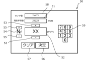
- FIG. 5 is a diagram showing an example of an input screen of the learning data input terminal.
- the input screen includes a current learning value display section 51, an input numerical value display section 52, an offset value input button 53, a current floor display section 54, a floor correction button 55, a decision button 56, a clear button 57, an APS data display section 58, and numeric keypad buttons 59.
- the APS data display section 58 and the numeric keypad buttons 59 are not essential to the input screen of the learning data input terminal 50.
- FIG. 6 is a flow chart for explaining the procedure for updating the car position table by manual input by a maintenance worker in the pre-learning process.
- step S100 of the pre-learning process first, the elevator car 8 is stopped at each floor according to the previous floor setting value.
- the pre-learning processing unit 41 accepts the input data manually input by the maintenance worker.
- the current floor display unit 54 displays the floor to be input, and the floor to be input can be corrected by the floor correction button 55.
- the current learning value display unit 51 displays the current APS learning data stored in the car position table.
- the maintenance worker confirms the absolute position of the car 8, for example, by visual inspection, and operates the offset value input button 53 to input the deviation of the car floor surface from the floor position as an offset value for the registered current APS learning data in millimeters.
- the input value display unit 52 displays the offset value input by the maintenance worker. To clear the input offset value, the clear button 57 is pressed. To register the input offset value, the decision button 56 is pressed.
- the maintenance staff may also directly input the offset value using the numeric keypad buttons 59.
- the maintenance staff may also manually align the car floor surface with the floor position, refer to the current APS data detection value displayed on the APS data display unit 58, and input the difference from the learned value as the offset value.
- step S104 the pre-learning processing unit 41 updates the APS learning data in the car position table based on the input data of the offset value entered by the maintenance worker. By executing such processing on each floor 4, the APS learning data for each floor 4 in the car position table is updated.
- top of the floor above the top floor and the bottom of the floor below the first floor, which is the lowest floor, may be outside the range in which the car 8 can move.
- a predetermined fixed value or a calculated value calculated from the top and bottom floors may be input into the APS learning data corresponding to the top and bottom.
- the pre-learning processing unit 41 calculates absolute positions corresponding to the center, upper end, and lower end in the vertical direction as the reference positions of the correction plate 20 while the car 8 is traveling.
- the elevator is made to travel back and forth and calculation processing similar to the acquisition processing and correction plate position calculation processing described below is performed, thereby making it possible to calculate the absolute positions corresponding to the center, upper end, and lower end.
- the pre-learning processing unit 41 updates the APS learning data in the car position table based on the calculated absolute positions.
- the acquisition processing unit 43 is a functional block for acquiring the APS detection position and APS detection speed at the time of end detection when the correction sensor 22 detects the end of the correction plate 20 while the car 8 travels at any speed in the ascending direction and the descending direction.
- This processing is hereinafter referred to as "acquisition processing.”
- the "APS detection position” here is absolute position information at the time of end detection, and more specifically, is APS data calculated by the APS 12.
- the "APS detection speed” is moving speed information at the time of end detection of the car 8 in which the APS sensor 16 is installed. The APS detection speed can be calculated, for example, from the amount of change over time in the APS data.
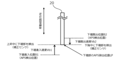
- the acquisition processing unit 43 acquires, as the APS detection position and APS detection speed, the lower end entry position B1 and the lower end entry speed Vb1 when the car 8 travels in the upward direction and detects the lower end of the correction plate 20, the upper end exit position A2 and the upper end exit speed Va2 when the car 8 travels in the upward direction and detects the upper end of the correction plate 20, the lower end exit position B2 and the lower end exit speed Vb2 when the car 8 travels in the downward direction and detects the lower end of the correction plate 20, and the upper end entry position A1 and the upper end entry speed Va1 when the car 8 travels in the downward direction and detects the upper end of the correction plate 20.
- the APS detection position and the APS detection speed are acquired in correspondence with the data detection time when the APS data was detected.
- FIG. 7 is a diagram showing an example of a correction plate position table stored in a storage device.
- the acquisition processing unit 43 records the acquired data in the correction plate position table.
- the data detection time is recorded as a timestamp in association with each piece of data.
- the acquisition processing unit 43 invalidates data associated with a timestamp earlier than a predetermined expiration date.
- the expiration date is, for example, one day. If multiple correction plates 20 are installed in the elevator shaft 2, the above-mentioned acquisition process is performed on each correction plate 20, and the correction plate position table is recorded in association with each plate number.
- the correction plate 20 is installed near the top floor, the upper end of the correction plate 20 may not be detected when the car 8 travels in the upward direction. Similarly, if the correction plate 20 is installed near the bottom floor, the lower end of the correction plate 20 may not be detected when the car 8 travels in the downward direction. In such cases, an invalid value is recorded in the correction plate position table for the value that was not obtained.
- the acquisition process may be performed during normal operation when elevator users are allowed to board the elevator, or during maintenance operation when users are restricted from boarding the elevator.
- the car 8 may be made to travel at a slower speed than the speed during normal operation. This improves the detection accuracy and reduces the size of the correction plate 20.
- the APS detection position and APS detection speed acquired in the acquisition process are used in the correction plate position calculation process described below.
- correction plate position calculation processing unit 44 is a functional block for calculating the positions of the upper end, lower end, and center as reference positions of the correction plate 20 using the APS detection position and APS detection speed acquired in the acquisition process. This process is hereinafter referred to as the "correction plate position calculation process.” In addition, the absolute position calculation value of the correction plate 20 calculated by the correction plate position calculation process is hereinafter referred to as the "APS calculated position.”
- FIG. 8 is a diagram for explaining a method for calculating the APS calculation position of the center of the correction plate in the correction plate position calculation process.
- the APS calculation position CP of the center in the movement path direction of the correction plate 20 is calculated by the following formula (1) using the upper end entry position A1, the upper end entry speed Va1, the lower end entry position B1, and the lower end entry speed Vb1.
- the upper end entry position A1, the upper end entry speed Va1, the lower end entry position B1, and the lower end entry speed Vb1 use the values recorded in the correction plate position table.
- the correction plate position calculation processing unit 44 records the calculated APS calculation position CP of the center in the correction plate position table.
- FIG. 9 is a diagram for explaining a method for calculating the APS calculated position of the upper end of the correction plate in the correction plate position calculation process.
- the APS calculated position UP of the upper end in the movement path direction of the correction plate 20 is calculated by the following formula (2) using the upper end entry position A1, the upper end entry velocity Va1, the upper end exit position A2, and the upper end exit velocity Va2.
- the upper end entry position A1, the upper end entry velocity Va1, the upper end exit position A2, and the upper end exit velocity Va2 use the values recorded in the correction plate position table.
- the correction plate position calculation processing unit 44 records the calculated APS calculated position UP of the upper end in the correction plate position table.
- FIG. 10 is a diagram for explaining a method for calculating the APS calculation position of the lower end of the correction plate in the correction plate position calculation process.
- the APS calculation position LP of the lower end in the movement path direction of the correction plate 20 is calculated by the following formula (3) using the lower end entry position B1, the lower end entry speed Vb1, the lower end exit position B2, and the lower end exit speed Vb2.
- the values recorded in the correction plate position table are used for the lower end entry position B1, the lower end entry speed Vb1, the lower end exit position B2, and the lower end exit speed Vb2.
- the correction plate position calculation processing unit 44 records the calculated APS calculation position LP of the lower end in the correction plate position table.
- the APS data detected by the APS sensor 16 is sent to the safety control device 10 by serial transmission, which causes data delays and deviations that depend on the running speed.
- the APS calculated position of the correction plate 20 is calculated taking into account the APS detection speed when the correction sensor 22 detects the end of the correction plate 20, so the effects of data delays caused by serial transmission can be eliminated. Therefore, even if the APS detection position and APS detection speed are acquired by running the car 8 at any speed in the acquisition process, the APS calculated position can be calculated with high accuracy.
- the correction plate 20 may be installed near the top floor, and the upper end of the correction plate 20 may not be detected by the correction sensor 22.
- the APS calculation position UP of the upper end and the APS calculation position CP of the central portion cannot be calculated, but at least the APS calculation position LP of the lower end can be calculated, and the calculated APS calculation position LP can be used to perform the correction process described below.
- the APS calculation position UP of the upper end can be calculated, and the calculated APS calculation position UP can be used to perform the correction process described below.
- the correction plate position calculation processing unit 44 only needs to be configured to calculate at least one of the APS calculation position CP of the central portion, the APS calculation position UP of the upper end, and the APS calculation position LP of the lower end according to the installation position of the correction plate 20.
- correction processing unit 45 is a functional block for executing a correction process to correct the APS learning data as a learning value pre-learned in the pre-learning process.
- Fig. 11 is a diagram for explaining a method for correcting the APS learning data in the correction process.
- a difference value of the APS calculation position with respect to the APS learning data is calculated at each of the upper end, lower end, and center of the correction plate 20. Then, for example, the minimum value of the calculated difference values is specified as the correction reference amount.
- Fig. 11 illustrates a case where the difference value at the center of the correction plate 20 is specified as the correction reference amount.
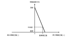
- the correction processing unit 45 calculates a linear correction amount by linearly changing the correction reference amount in response to the position in the movement path direction, starting from the top, which is a fixed point of the APS tape 14.
- FIG. 12 is a diagram showing the linear correction amount corresponding to the position in the movement path direction. As shown in this figure, the linear correction amount changes linearly in response to the position in the movement path direction, so that the linear correction amount becomes the correction reference amount at the center of the correction plate 20 and becomes zero at the top of the APS tape 14.
- the correction processing unit 45 records the calculated linear correction amount in the car position table.
- the correction processing unit 45 identifies and adds the corresponding linear correction amount to the APS data read by the APS 12 according to the relationship between the APS learning data and the linear correction amount recorded in the cage position table, and calculates the current absolute position of the cage 8.
- the above correction process makes it possible to associate accurate absolute position information with the car position of car 8 even if the APS tape 14 expands or contracts due to building deformation or temperature changes. This makes it possible to always detect the absolute position of car 8 with high accuracy in the car position calculation process.
- the degenerate operation control unit 46 is a functional block for performing degenerate operation.
- the degenerate operation control unit 46 cuts off the power supply to the hoist 3 by cutting off the safety circuit using the safety circuit breaker unit 38, and temporarily stops the car. Then, just before instructing the elevator control device 6 to perform degenerate operation, the degenerate operation control unit 46 reconnects the safety circuit using the safety circuit breaker unit 38 and resumes the power supply to the hoist 3.
- the degenerate operation control unit 46 commands the elevator control device 6 to perform degenerate operation, the elevator control device 6 moves the car 8 at a low speed toward the nearest evacuation floor.
- Figures 13 and 14 are flowcharts of routines executed in the elevator system.
- the routines shown in Figures 13 and 14 are executed in the processing unit 30 of the safety control device 10, for example, when a certain time has elapsed since the previous update of the correction reference amount.
- step S110 it is determined whether the correction sensor 22 installed on the car 8 has entered the correction plate 20 based on the correction sensor signal of the correction sensor 22. If the determination is not true, step S110 is executed again, and if the determination is true, the process proceeds to step S112.
- step S112 the entry position and entry speed at the time of entry are recorded in the correction plate position table.
- the lower end entry position B1 and the lower end entry speed Vb1 are recorded in the correction plate position table.
- the upper end entry position A1 and the upper end entry speed Va1 are recorded in the correction plate position table.
- step S114 it is determined whether the entry position and entry speed at the time of entry in the opposite direction to the entry position and entry speed recorded in step S112 of this routine are recorded in the correction plate position table. If the determination is not true, it is determined that the APS calculated position CP of the center of the correction plate 20 cannot be calculated, and the process proceeds to step S118. On the other hand, if the determination is true, it is determined that the APS calculated position CP can be calculated, and the process proceeds to step S116.
- step S116 the APS calculated position CP and the correction reference amount (A) corresponding to the APS calculated position CP are calculated.
- step S118 it is determined whether the exit position and exit speed at the time of exit in the opposite direction to the entry direction corresponding to the entry position and entry speed recorded in the immediately preceding step S112 are recorded in the correction plate position table. If the determination is not true, the process proceeds to step S124, and if the determination is true, the process proceeds to step S120.
- step S120 if an entry during an upward movement of the car 8 is recognized in step S110 of this routine, the APS calculation position LP of the lower end of the correction plate 20 is calculated. Alternatively, if an entry during a downward movement of the car 8 is recognized in step S110 of this routine, the APS calculation position UP of the upper end of the correction plate 20 is calculated. In addition, a correction reference amount (B) corresponding to the calculated APS calculation position LP or APS calculation position UP is calculated.
- step S122 the processing proceeds to step S122.
- step S122 the correction reference amount is updated to the correction reference amount (A) calculated in step S116 or the correction reference amount (B) calculated in step S120, whichever has the smaller absolute value.
- step S124 it is determined whether the correction sensor 22 installed on the car 8 has escaped from the correction plate 20 based on the correction sensor signal of the correction sensor 22. If the determination is not true, step S124 is executed again, and if the determination is true, the process proceeds to step S126.
- step S126 if the escape occurred while the car 8 was ascending, the upper end escape position A2 and the upper end escape velocity Va2 are recorded in the correction plate position table. Alternatively, if the escape occurred while the car 8 was descending, the lower end escape position B2 and the lower end escape velocity Vb2 are recorded in the correction plate position table.
- step S128 the processing proceeds to step S128.
- step S1208 it is determined whether the exit direction in step S126 is the opposite direction to the entry direction in step S110. If the determination is negative, the processing of this routine ends, and if the determination is positive, the processing proceeds to step S130.
- step S130 if an entry during an upward movement of the car 8 is recognized in step S110 of this routine, the APS calculation position UP of the upper end of the correction plate 20 is calculated. Alternatively, if an entry during a downward movement of the car 8 is recognized in step S110 of this routine, the APS calculation position LP of the lower end of the correction plate 20 is calculated. In addition, a correction reference amount (C) corresponding to the calculated APS calculation position LP or APS calculation position UP is calculated.
- step S132 the processing proceeds to step S132.
- step S132 the correction reference amount is updated to the smallest absolute value among the correction reference amount (A) calculated in step S116, the correction reference amount (B) calculated in step S120, and the correction reference amount (C) calculated in step S130.
- the processing of step S132 proceeds to step S134.
- step S134 a linear correction amount is calculated based on the correction reference amount.
- the linear correction amount is added to the detected APS data to correct the absolute position of car 8.
- the elevator system of the first embodiment may employ the following modified aspects. These modified aspects may also be applied to elevator systems of other embodiments described later.
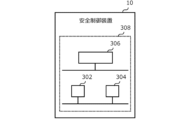
- Safety control device 10 Fig. 15 is a diagram showing a modified example of hardware resources in the processing unit 30 of the safety controller 10.
- the safety controller 10 includes a processing circuit 308 including, for example, a processor 302, a memory 304, and dedicated hardware 306.
- Fig. 15 shows an example in which some of the functions of the safety controller 10 are realized by the dedicated hardware 306. All of the functions of the safety controller 10 may be realized by the dedicated hardware 306.
- the dedicated hardware 306 a single circuit, a composite circuit, a programmed processor, a parallel programmed processor, an ASIC, an FPGA, or a combination thereof can be adopted.
- the safety control device 10 and the elevator control device 6 may be configured as a single control device.
- correction processing unit 45 The correction starting point when calculating the linear correction amount in the correction process is not limited to the top of the APS tape 14. In other words, when an APS tape with the bottom as a fixed point is used, the bottom of the APS tape 14 may be the correction starting point.
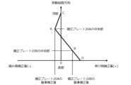
- FIG. 16 is a diagram showing an example of calculating a linear correction amount corresponding to the position in the moving path direction using multiple correction reference amounts.
- the linear correction amount between the top of the APS tape 14 and the center of the correction plate 20A becomes the correction reference amount of the correction plate 20A at the center of the correction plate 20A, and changes linearly corresponding to the position in the moving path direction so as to be zero at the top of the APS tape 14.
- the linear correction amount between the center of the correction plate 20A and the center of the correction plate 20B becomes the correction reference amount of the correction plate 20A at the center of the correction plate 20A, and changes linearly corresponding to the position in the moving path direction so as to be the correction reference amount of the correction plate 20B at the center of the correction plate 20B.
- This type of correction process increases the likelihood that the APS learning data can be appropriately corrected when the degree of expansion and contraction of the APS tape 14 varies depending on the position in the movement path direction.
- the APS tape 14 tends to expand and contract more as the temperature fluctuations become greater. For this reason, for example, in a hoistway that has a see-through area where the outside can be seen from inside the hoistway, the temperature fluctuations in the see-through area are greater than in other areas, and so there is a risk that the degree of expansion and contraction of the APS tape 14 in the see-through area will be greater than the degree of expansion and contraction in other areas. Therefore, in such special hoistways, it is preferable to install correction plates 20 in the temperature fluctuation area where the temperature fluctuations are greater than in other areas, and in the other areas.
- the method of calculating the APS detected speed is not limited to the method of calculating from the amount of change in the APS data over time. That is, since the APS sensor 16 is installed on the upper part of the car 8, the APS detected speed can also be calculated using the encoder of the hoist 3.
- Embodiment 2 In the second embodiment, differences from the example disclosed in the first embodiment will be described in particular detail. For features not described in the second embodiment, any of the features of the example disclosed in the first embodiment may be adopted.
- the elevator system of the second embodiment is characterized by the installation location of the correction plate 20 and the degenerate operation using the correction plate 20.
- the correction plate 20 which also functions as an evacuation floor plate, is installed at the evacuation floor position detected by the correction sensor 22 when the car 8 stops at the evacuation floor.
- the degenerate operation control unit 46 is a functional block for performing degenerate operation.
- the degenerate operation here includes emergency stopping of the car 8 and low-speed operation to the nearest evacuation floor. Specifically, degenerate operation is performed when an abnormality occurs in the APS 12, or when an error occurs in the acquisition process or correction process, etc.
- the correction sensor 22 detects the correction plate 20 installed at the evacuation floor position, thereby detecting that the car 8 has moved to the evacuation floor. This type of operation makes it possible to perform degenerate operation to move the car 8 to the evacuation floor, even if an abnormality occurs in the APS 12.
- Fig. 17 is a flowchart of a routine executed in the elevator system of the second embodiment.
- the routine shown in Fig. 17 is executed in the processing unit 30 of the safety control device 10.
- step S200 it is determined whether an abnormality in APS 12 has been detected.
- abnormalities in APS 12 here include a loss of communication from APS 12, the occurrence of a communication error, or a signal that is different from normal being sent from APS 12. If the determination is not true, the process proceeds to step S202, and if the determination is true, the process proceeds to step S204.
- step S202 it is determined whether or not there is an error. Specifically, it is determined that there is an error if the correction sensor 22 detects the correction plate 20 and the cage 8 is not near the correction plate 20. It is also determined that there is an error if the correction sensor 22 does not detect the correction plate 20 and the cage 8 is near the correction plate 20. It is also determined that there is an error if the correction reference amount calculated in the correction process is greater than a predetermined abnormality determination threshold. As a result, if the determination is not made, the process returns to the beginning of this routine, and if the determination is made, the process proceeds to step S204.
- step 204 the safety circuit (not shown) is cut off by the safety circuit cutoff unit 38, which stops the hoist 3. This brings the car 8 to an emergency stop.
- step S206 the process proceeds to step S206.
- step S206 the safety circuit is reconnected by the safety circuit breaker 38, and an operation command is sent from the safety control device 30 to the elevator control device 6 to operate the car 8 at a low speed in the direction of the nearest evacuation floor. This causes the car 8 to move at a low speed in the direction of the nearest evacuation floor.
- step S208 the processing proceeds to step S208.
- step S208 it is determined whether the correction sensor 22 has detected the correction plate 20 installed at the evacuation floor position. If the determination is negative, the process proceeds to step S210, and if the determination is positive, the process proceeds to step S214.
- step S210 it is determined whether car 8 has traveled a certain distance or more, or whether a predetermined grace period has expired.
- the certain distance here is set to the distance that car 8 can reach from the emergency stop position to the nearest evacuation floor.
- the travel distance of car 8 can be counted using APS 12, and if an abnormality in APS 12 is detected, the encoder of the hoist 3 is used.
- the process proceeds to step S212, and if the determination is negative, the process returns to step S208 again. In other words, the determination in step S208 is repeatedly executed until the determination in step S220 is positive.
- step S212 the safety circuit is interrupted by the safety circuit interruption unit 38, thereby stopping the hoist 3. This stops the car 8.
- the processing of step 212 proceeds to step S216.
- step S214 after car 8 has stopped, the doors are opened and closed to allow passengers to disembark at the evacuation floor.
- step S216 elevator service is stopped and this routine is terminated.
- the speed command value may be obtained from the elevator control device 6. In either case, under normal circumstances, the speed obtained from the APS 12 is compared with the encoder value or the speed command value to confirm the accuracy of the encoder value or the speed command value.
Landscapes
- Indicating And Signalling Devices For Elevators (AREA)
- Maintenance And Inspection Apparatuses For Elevators (AREA)
Priority Applications (3)
| Application Number | Priority Date | Filing Date | Title |
|---|---|---|---|
| PCT/JP2023/027584 WO2025022650A1 (ja) | 2023-07-27 | 2023-07-27 | エレベーターシステム |
| CN202380100628.6A CN121568887A (zh) | 2023-07-27 | 2023-07-27 | 电梯系统 |
| JP2025535533A JPWO2025022650A1 (https=) | 2023-07-27 | 2023-07-27 |
Applications Claiming Priority (1)
| Application Number | Priority Date | Filing Date | Title |
|---|---|---|---|
| PCT/JP2023/027584 WO2025022650A1 (ja) | 2023-07-27 | 2023-07-27 | エレベーターシステム |
Publications (1)
| Publication Number | Publication Date |
|---|---|
| WO2025022650A1 true WO2025022650A1 (ja) | 2025-01-30 |
Family
ID=94374179
Family Applications (1)
| Application Number | Title | Priority Date | Filing Date |
|---|---|---|---|
| PCT/JP2023/027584 Pending WO2025022650A1 (ja) | 2023-07-27 | 2023-07-27 | エレベーターシステム |
Country Status (3)
| Country | Link |
|---|---|
| JP (1) | JPWO2025022650A1 (https=) |
| CN (1) | CN121568887A (https=) |
| WO (1) | WO2025022650A1 (https=) |
Citations (3)
| Publication number | Priority date | Publication date | Assignee | Title |
|---|---|---|---|---|
| WO2011089691A1 (ja) * | 2010-01-20 | 2011-07-28 | 三菱電機株式会社 | エレベーター装置 |
| JP2021066567A (ja) * | 2019-10-24 | 2021-04-30 | 株式会社日立ビルシステム | エレベータ装置 |
| US20220135369A1 (en) * | 2020-11-05 | 2022-05-05 | Otis Elevator Company | Elevator position reference systems and monitoring building settlement using an elevator position reference system |
-
2023
- 2023-07-27 CN CN202380100628.6A patent/CN121568887A/zh active Pending
- 2023-07-27 JP JP2025535533A patent/JPWO2025022650A1/ja active Pending
- 2023-07-27 WO PCT/JP2023/027584 patent/WO2025022650A1/ja active Pending
Patent Citations (3)
| Publication number | Priority date | Publication date | Assignee | Title |
|---|---|---|---|---|
| WO2011089691A1 (ja) * | 2010-01-20 | 2011-07-28 | 三菱電機株式会社 | エレベーター装置 |
| JP2021066567A (ja) * | 2019-10-24 | 2021-04-30 | 株式会社日立ビルシステム | エレベータ装置 |
| US20220135369A1 (en) * | 2020-11-05 | 2022-05-05 | Otis Elevator Company | Elevator position reference systems and monitoring building settlement using an elevator position reference system |
Also Published As
| Publication number | Publication date |
|---|---|
| JPWO2025022650A1 (https=) | 2025-01-30 |
| CN121568887A (zh) | 2026-02-24 |
Similar Documents
| Publication | Publication Date | Title |
|---|---|---|
| US9617115B2 (en) | Method for determining and using parameters associated with run time of elevators and an elevator system configured to perform same | |
| EP1431229B1 (en) | Elevator device | |
| CN101023017B (zh) | 测定电梯轿厢止动精度的状况监测方法和状况监测系统 | |
| US20250153972A1 (en) | Elevator control system | |
| US20090166133A1 (en) | Positioning Method in an Elevator System | |
| EP3584208B1 (en) | Position reference device for elevator | |
| US20190062106A1 (en) | Elevator position detection systems | |
| CN114104885A (zh) | 轿厢位置确定装置以及轿厢位置确定方法 | |
| KR102864415B1 (ko) | 엘리베이터 장치 | |
| US5085294A (en) | Elevator control apparatus | |
| US9266699B2 (en) | Elevator system and operation thereof | |
| JP6490238B2 (ja) | エレベーターの制御装置 | |
| WO2025022650A1 (ja) | エレベーターシステム | |
| JP5195766B2 (ja) | エレベータシステム及びそれに用いる着床位置検出装置 | |
| KR20120046278A (ko) | 엘리베이터 제어장치 | |
| CN112623896A (zh) | 电梯层高修正方法 | |
| WO2025186505A1 (en) | A method and an elevator rope elongation determination system for generating elongation data of an elevator hoisting rope arrangement | |
| CN111532914B (zh) | 一种电梯平层的控制方法及电梯 | |
| US20220017331A1 (en) | Elevator control apparatus | |
| WO2023135648A1 (ja) | 位置演算装置およびエレベーターシステム | |
| KR20240146050A (ko) | 엘리베이터 시스템 | |
| JP2025001885A (ja) | エレベータの位置検出システム並びにエレベータの位置検出方法 | |
| KR960010231B1 (ko) | 엘리베이터의 셀렉터오동작방지방법 | |
| HK40010422A (en) | Car location determining device and car location determining method | |
| HK40010422B (en) | Car location determining device and car location determining method |
Legal Events
| Date | Code | Title | Description |
|---|---|---|---|
| 121 | Ep: the epo has been informed by wipo that ep was designated in this application |
Ref document number: 23946729 Country of ref document: EP Kind code of ref document: A1 |
|
| ENP | Entry into the national phase |
Ref document number: 2025535533 Country of ref document: JP Kind code of ref document: A |