WO2025022650A1 - エレベーターシステム - Google Patents
エレベーターシステム Download PDFInfo
- Publication number
- WO2025022650A1 WO2025022650A1 PCT/JP2023/027584 JP2023027584W WO2025022650A1 WO 2025022650 A1 WO2025022650 A1 WO 2025022650A1 JP 2023027584 W JP2023027584 W JP 2023027584W WO 2025022650 A1 WO2025022650 A1 WO 2025022650A1
- Authority
- WO
- WIPO (PCT)
- Prior art keywords
- absolute position
- car
- correction
- aps
- processing unit
- Prior art date
- Legal status (The legal status is an assumption and is not a legal conclusion. Google has not performed a legal analysis and makes no representation as to the accuracy of the status listed.)
- Pending
Links
Images








Classifications
-
- B—PERFORMING OPERATIONS; TRANSPORTING
- B66—HOISTING; LIFTING; HAULING
- B66B—ELEVATORS; ESCALATORS OR MOVING WALKWAYS
- B66B3/00—Applications of devices for indicating or signalling operating conditions of elevators
- B66B3/02—Position or depth indicators
Definitions
- This disclosure relates to an elevator system equipped with an absolute positioning system that detects the absolute position of the elevator car.
- Patent Document 1 discloses technology relating to a method for adjusting a car position detection device in which a magnetic tape is stretched along the elevator shaft along the elevator path of the car, and a magnetic sensor that detects the magnetic tape is installed in the car.
- a just level sensor is provided to detect when the car has landed at each floor landing.
- the just level sensor has a reflector installed at the threshold of the landing at each floor, and a photoelectric sensor installed in the car, and is designed to detect the reflector when the car has come to a position where it will land accurately at each landing. Then, during the adjustment process, the car is moved in the elevator shaft, and the position on the magnetic tape when the just level sensor is activated is recorded as just level.
- Elevators equipped with an absolute positioning system (APS), which detects the absolute position of the car by reading information from a tape installed along the entire length of the elevator shaft using a sensor installed in the car, such as the car position detection device in Patent Document 1, have the problem that the measurement of the car position is shifted due to expansion and contraction of the tape caused by deformation of the building or temperature changes.
- the technology in Patent Document 1 discloses that this problem is solved by a just level sensor.
- This disclosure has been made to solve the problems described above, and aims to provide an elevator system that can detect the absolute position of the car with high accuracy by correcting errors in an absolute position measuring system with a configuration that improves ease of installation and mounting.
- the elevator system disclosed herein is applied to an elevator system including an absolute positioning system that detects absolute position information corresponding to the absolute position of a car traveling in a hoistway in the direction of the moving path, and an elevator control device that controls the operation of the car based on the detected absolute position information.
- the elevator system includes a detectable object fixedly installed in the hoistway, a detectable object detection device attached to the car and detecting the detectable object, a storage device that stores a learning value that has been previously learned as an absolute position corresponding to a reference position of the detectable object in the moving path direction, and a control device.
- the control device includes an acquisition processing unit that acquires absolute position information detected by the absolute positioning system when the detectable object detection device detects an end of the detectable object while the car travels in the upward and downward directions at any speed, and movement speed information of the car at the time of end detection, a calculation processing unit that calculates an absolute position calculation value of the reference position based on the absolute position information and movement speed information acquired by the acquisition processing unit, and a correction processing unit that corrects the absolute position information detected by the absolute positioning system based on a comparison between the learning value and the absolute position calculation value.
- an elevator system that can detect the absolute position of the car with high accuracy by correcting errors in an absolute position measuring system with a configuration that improves ease of installation and setup.
- FIG. 1 is a schematic configuration diagram of an elevator provided in an elevator system according to a first embodiment.
- 2 is a diagram for explaining functional blocks provided in the safety control device.
- FIG. FIG. 4 is a functional block diagram showing functions realized by a processing unit.
- FIG. 4 is a diagram showing an example of a car position table stored in a storage device.
- FIG. 13 is a diagram showing an example of an input screen of a learning data input terminal. 13 is a flowchart for explaining a procedure for updating the car position table through manual input by a maintenance worker in the advance learning process.
- FIG. 11 is a diagram showing an example of a correction plate position table stored in a storage device.
- FIGS. 13A and 13B are diagrams for explaining a method for calculating the APS calculation position of the center of the correction plate in the correction plate position calculation process.
- 13A and 13B are diagrams for explaining a method for calculating the APS calculation position of the upper end portion of the correction plate in the correction plate position calculation process.
- 13A and 13B are diagrams for explaining a method for calculating the APS calculation position of the lower end of the correction plate in the correction plate position calculation process.
- 11 is a diagram for explaining a method of correcting APS learning data in the correction process.
- FIG. 13 is a diagram showing a linear correction amount corresponding to a position in a movement path direction.
- FIG. 4 is a flowchart of a routine executed in the elevator system according to the first embodiment.
- FIG. 4 is a flowchart of a routine executed in the elevator system according to the first embodiment.
- FIG. 13 is a diagram illustrating a modified example of hardware resources in a processing unit of the safety control device.
- 13A and 13B are diagrams illustrating an example in which a linear correction amount corresponding to a position in a movement path direction is calculated using a plurality of correction reference amounts.
- 11 is a flowchart of a routine executed in the elevator system of embodiment 2.
- Embodiment 1. 1-1 Schematic configuration of an elevator system according to a first embodiment
- Fig. 1 is a schematic configuration diagram of an elevator provided in an elevator system according to a first embodiment.
- An elevator of an elevator system 100 according to a first embodiment is installed in a facility consisting of a building or the like having multiple floors.
- An elevator hoistway 2 is provided in the facility.
- the hoistway 2 is a space that is long in the vertical direction and spans multiple floors 4.
- the elevator is mainly composed of a hoist 3, an elevator control device 6, and a car 8.
- the car 8 is a device that transports passengers inside between multiple floors 4 by traveling up and down the hoistway 2, which is the direction of the travel path.
- the car 8 travels by the hoist 3 installed at the top of the hoistway 2.
- the elevator control device 6 corresponds to a control panel that controls the operation of the elevator.
- the operation of the elevator controlled by the elevator control device 6 includes, for example, opening and closing the doors, managing registered calls, and running the car 8 in response to calls.
- the elevator is equipped with an absolute positioning system 12.
- the absolute positioning system is also referred to as "APS" below.
- the APS 12 is a system that functions as an absolute position detection device that detects absolute position information corresponding to the position of the car 8 in the elevator shaft 2 in the direction of the travel path of the car 8.
- the APS 12 is equipped with an APS tape 14 and an APS sensor 16.
- the APS tape 14 is a long body that is provided along the direction of the travel path in the elevator shaft 2.
- absolute position information is continuously set on the APS tape 14 in accordance with the position in the direction of the travel path in the elevator shaft 2.
- the absolute position information is information that is set by continuously varying the magnetic characteristics or optical characteristics from the top to the bottom in the vertical direction of the APS tape 14.
- the absolute position information read from the APS tape 14 is hereinafter also referred to as "APS data”.
- the APS sensor 16 is a sensor for reading APS data from the APS tape 14.
- the APS sensor 16 is installed on the car 8 in a position facing the APS tape 14.
- the detection method used for the APS sensor 16 is a method capable of reading APS data from the APS tape 14, such as a magnetic method or an optical method.
- the APS data detected by the APS sensor 16 is serially transmitted to the safety control device 10, which will be described later.
- the elevator is equipped with one or more correction plates 20 and a correction sensor 22.
- the correction plate 20 is a rectangular metal plate fixedly installed in the elevator shaft 2.
- the correction plate 20 is also referred to as the "detectable object" below.
- multiple correction plates 20 may be installed in the elevator shaft 2 at intervals of several tens of meters along the direction of the travel path.
- the correction plates 20 do not have to be installed in a location corresponding to the floor 4.
- the correction plate 20, which also functions as an evacuation floor plate used in the degenerate operation described later in the second embodiment is installed at an evacuation floor position corresponding to the floor of the evacuation floor.
- the correction sensor 22 is a sensor device that detects the end of the correction plate 20, and is also called a "detectable object detection device.”
- the correction sensor 22 is installed on the car 8 in a position facing the correction plate 20. Typically, the correction sensor 22 detects entry from the lower end and exit from the upper end of the correction plate 20 when the car 8 is rising. The correction sensor 22 also detects entry from the upper end and exit from the lower end of the correction plate 20 when the car 8 is descending.
- the detected correction sensor signal is transmitted in parallel to the safety control device 10.
- the safety control device 10 is a control device that is responsible for safety control of the elevator.
- Figure 2 is a diagram for explaining the functional blocks of the safety control device.
- the safety control device 10 has, as its functions, a processing unit 30, an APS data receiving unit 32, a correction sensor signal input unit 34, a learning data input unit 36, a safety circuit interruption unit 38, and a memory device 40.
- the processing unit 30 includes a processor 302 and a memory 304.
- the processor 302 executes various processes.
- the processor 302 is, for example, a microcomputer.
- Various data is stored in the memory 304. Examples of the memory 304 include a volatile memory and a non-volatile memory.
- Various programs are stored in the memory 304.
- the functions of the processing unit 30 are realized by the processor 302 executing the various programs. The functions of the processing unit 30 will be described later.
- the APS data receiving unit 32 is a functional block for receiving APS data serially transmitted from the APS sensor.
- the received APS data is temporarily stored in the memory of the processing unit 30.
- the correction sensor signal input unit 34 is a functional block for receiving the input of the correction sensor signal transmitted in parallel from the correction sensor 22.
- the received correction sensor signal is temporarily stored in the memory of the processing unit 30.
- the learning data input unit 36 is a functional block for accepting input of learning data serially transmitted from a learning data input terminal 50 described later.
- the received learning data is temporarily stored in the memory of the processing unit 30.
- the safety circuit interruption unit 38 is a functional block for interrupting the power supply to the hoist 3 and stopping the car by interrupting a safety circuit (not shown) when the absolute position of the car 8 cannot be detected due to an abnormality in the APS 12, etc. Furthermore, when the safety control device 10 commands the elevator control device 6 to perform degenerate operation, the safety circuit interruption unit 38 also has a function of reconnecting the safety circuit immediately before the command for degenerate operation is issued, and resuming the power supply to the hoist 3. Note that the degenerate operation here refers to an operation in which, when an abnormality occurs in the APS 12, the car 8 is brought to an emergency stop and then moved at a low speed toward the nearest evacuation floor. The specific operation of the degenerate operation will be described in detail later.
- the storage device 40 is a device that stores a cage position table and a correction plate position table, which will be described later. Examples of the storage device 40 include a volatile memory and a non-volatile memory.
- the storage device 40 may be configured as a part of the processing unit 30.
- the storage device 40 may be the memory 304.
- Fig. 3 is a functional block diagram showing functions realized by the processing unit.
- the processing unit 30 includes, as functional blocks for executing various processes, a pre-learning processing unit 41, an acquisition processing unit 43, a correction plate position calculation processing unit 44, a correction processing unit 45, and a degenerate operation control unit 46. Specific processes in these functional blocks will be described below.
- the advance learning processing unit 41 is a functional block for learning absolute position information corresponding to the stop position of the car 8 and the position of the correction plate 20 on each floor 4 and updating the car position table. This processing is hereinafter referred to as "advance learning processing". The advance learning processing may be performed not only for the first time after the installation of the elevator, but also periodically.
- FIG. 4 is a diagram showing an example of a car position table stored in a storage device. As shown in this figure, the car position table is a table in which APS learning data that has learned an absolute position corresponding to the position of the car 8 is stored.
- the advance learning processing unit 41 accepts APS learning data corresponding to the stop position of the car 8 manually input by a maintenance worker and updates the car position table.
- a learning data input terminal 50 is used for manual input by the maintenance worker.
- the learning data input terminal 50 is an external input terminal that is connected to the safety control device 10 and used in the advance learning processing.
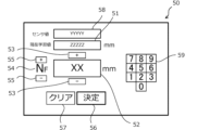
- FIG. 5 is a diagram showing an example of an input screen of the learning data input terminal.
- the input screen includes a current learning value display section 51, an input numerical value display section 52, an offset value input button 53, a current floor display section 54, a floor correction button 55, a decision button 56, a clear button 57, an APS data display section 58, and numeric keypad buttons 59.
- the APS data display section 58 and the numeric keypad buttons 59 are not essential to the input screen of the learning data input terminal 50.
- FIG. 6 is a flow chart for explaining the procedure for updating the car position table by manual input by a maintenance worker in the pre-learning process.
- step S100 of the pre-learning process first, the elevator car 8 is stopped at each floor according to the previous floor setting value.
- the pre-learning processing unit 41 accepts the input data manually input by the maintenance worker.
- the current floor display unit 54 displays the floor to be input, and the floor to be input can be corrected by the floor correction button 55.
- the current learning value display unit 51 displays the current APS learning data stored in the car position table.
- the maintenance worker confirms the absolute position of the car 8, for example, by visual inspection, and operates the offset value input button 53 to input the deviation of the car floor surface from the floor position as an offset value for the registered current APS learning data in millimeters.
- the input value display unit 52 displays the offset value input by the maintenance worker. To clear the input offset value, the clear button 57 is pressed. To register the input offset value, the decision button 56 is pressed.
- the maintenance staff may also directly input the offset value using the numeric keypad buttons 59.
- the maintenance staff may also manually align the car floor surface with the floor position, refer to the current APS data detection value displayed on the APS data display unit 58, and input the difference from the learned value as the offset value.
- step S104 the pre-learning processing unit 41 updates the APS learning data in the car position table based on the input data of the offset value entered by the maintenance worker. By executing such processing on each floor 4, the APS learning data for each floor 4 in the car position table is updated.
- top of the floor above the top floor and the bottom of the floor below the first floor, which is the lowest floor, may be outside the range in which the car 8 can move.
- a predetermined fixed value or a calculated value calculated from the top and bottom floors may be input into the APS learning data corresponding to the top and bottom.
- the pre-learning processing unit 41 calculates absolute positions corresponding to the center, upper end, and lower end in the vertical direction as the reference positions of the correction plate 20 while the car 8 is traveling.
- the elevator is made to travel back and forth and calculation processing similar to the acquisition processing and correction plate position calculation processing described below is performed, thereby making it possible to calculate the absolute positions corresponding to the center, upper end, and lower end.
- the pre-learning processing unit 41 updates the APS learning data in the car position table based on the calculated absolute positions.
- the acquisition processing unit 43 is a functional block for acquiring the APS detection position and APS detection speed at the time of end detection when the correction sensor 22 detects the end of the correction plate 20 while the car 8 travels at any speed in the ascending direction and the descending direction.
- This processing is hereinafter referred to as "acquisition processing.”
- the "APS detection position” here is absolute position information at the time of end detection, and more specifically, is APS data calculated by the APS 12.
- the "APS detection speed” is moving speed information at the time of end detection of the car 8 in which the APS sensor 16 is installed. The APS detection speed can be calculated, for example, from the amount of change over time in the APS data.
- the acquisition processing unit 43 acquires, as the APS detection position and APS detection speed, the lower end entry position B1 and the lower end entry speed Vb1 when the car 8 travels in the upward direction and detects the lower end of the correction plate 20, the upper end exit position A2 and the upper end exit speed Va2 when the car 8 travels in the upward direction and detects the upper end of the correction plate 20, the lower end exit position B2 and the lower end exit speed Vb2 when the car 8 travels in the downward direction and detects the lower end of the correction plate 20, and the upper end entry position A1 and the upper end entry speed Va1 when the car 8 travels in the downward direction and detects the upper end of the correction plate 20.
- the APS detection position and the APS detection speed are acquired in correspondence with the data detection time when the APS data was detected.
- FIG. 7 is a diagram showing an example of a correction plate position table stored in a storage device.
- the acquisition processing unit 43 records the acquired data in the correction plate position table.
- the data detection time is recorded as a timestamp in association with each piece of data.
- the acquisition processing unit 43 invalidates data associated with a timestamp earlier than a predetermined expiration date.
- the expiration date is, for example, one day. If multiple correction plates 20 are installed in the elevator shaft 2, the above-mentioned acquisition process is performed on each correction plate 20, and the correction plate position table is recorded in association with each plate number.
- the correction plate 20 is installed near the top floor, the upper end of the correction plate 20 may not be detected when the car 8 travels in the upward direction. Similarly, if the correction plate 20 is installed near the bottom floor, the lower end of the correction plate 20 may not be detected when the car 8 travels in the downward direction. In such cases, an invalid value is recorded in the correction plate position table for the value that was not obtained.
- the acquisition process may be performed during normal operation when elevator users are allowed to board the elevator, or during maintenance operation when users are restricted from boarding the elevator.
- the car 8 may be made to travel at a slower speed than the speed during normal operation. This improves the detection accuracy and reduces the size of the correction plate 20.
- the APS detection position and APS detection speed acquired in the acquisition process are used in the correction plate position calculation process described below.
- correction plate position calculation processing unit 44 is a functional block for calculating the positions of the upper end, lower end, and center as reference positions of the correction plate 20 using the APS detection position and APS detection speed acquired in the acquisition process. This process is hereinafter referred to as the "correction plate position calculation process.” In addition, the absolute position calculation value of the correction plate 20 calculated by the correction plate position calculation process is hereinafter referred to as the "APS calculated position.”
- FIG. 8 is a diagram for explaining a method for calculating the APS calculation position of the center of the correction plate in the correction plate position calculation process.
- the APS calculation position CP of the center in the movement path direction of the correction plate 20 is calculated by the following formula (1) using the upper end entry position A1, the upper end entry speed Va1, the lower end entry position B1, and the lower end entry speed Vb1.
- the upper end entry position A1, the upper end entry speed Va1, the lower end entry position B1, and the lower end entry speed Vb1 use the values recorded in the correction plate position table.
- the correction plate position calculation processing unit 44 records the calculated APS calculation position CP of the center in the correction plate position table.
- FIG. 9 is a diagram for explaining a method for calculating the APS calculated position of the upper end of the correction plate in the correction plate position calculation process.
- the APS calculated position UP of the upper end in the movement path direction of the correction plate 20 is calculated by the following formula (2) using the upper end entry position A1, the upper end entry velocity Va1, the upper end exit position A2, and the upper end exit velocity Va2.
- the upper end entry position A1, the upper end entry velocity Va1, the upper end exit position A2, and the upper end exit velocity Va2 use the values recorded in the correction plate position table.
- the correction plate position calculation processing unit 44 records the calculated APS calculated position UP of the upper end in the correction plate position table.
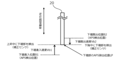
- FIG. 10 is a diagram for explaining a method for calculating the APS calculation position of the lower end of the correction plate in the correction plate position calculation process.
- the APS calculation position LP of the lower end in the movement path direction of the correction plate 20 is calculated by the following formula (3) using the lower end entry position B1, the lower end entry speed Vb1, the lower end exit position B2, and the lower end exit speed Vb2.
- the values recorded in the correction plate position table are used for the lower end entry position B1, the lower end entry speed Vb1, the lower end exit position B2, and the lower end exit speed Vb2.
- the correction plate position calculation processing unit 44 records the calculated APS calculation position LP of the lower end in the correction plate position table.
- the APS data detected by the APS sensor 16 is sent to the safety control device 10 by serial transmission, which causes data delays and deviations that depend on the running speed.
- the APS calculated position of the correction plate 20 is calculated taking into account the APS detection speed when the correction sensor 22 detects the end of the correction plate 20, so the effects of data delays caused by serial transmission can be eliminated. Therefore, even if the APS detection position and APS detection speed are acquired by running the car 8 at any speed in the acquisition process, the APS calculated position can be calculated with high accuracy.
- the correction plate 20 may be installed near the top floor, and the upper end of the correction plate 20 may not be detected by the correction sensor 22.
- the APS calculation position UP of the upper end and the APS calculation position CP of the central portion cannot be calculated, but at least the APS calculation position LP of the lower end can be calculated, and the calculated APS calculation position LP can be used to perform the correction process described below.
- the APS calculation position UP of the upper end can be calculated, and the calculated APS calculation position UP can be used to perform the correction process described below.
- the correction plate position calculation processing unit 44 only needs to be configured to calculate at least one of the APS calculation position CP of the central portion, the APS calculation position UP of the upper end, and the APS calculation position LP of the lower end according to the installation position of the correction plate 20.
- correction processing unit 45 is a functional block for executing a correction process to correct the APS learning data as a learning value pre-learned in the pre-learning process.
- Fig. 11 is a diagram for explaining a method for correcting the APS learning data in the correction process.
- a difference value of the APS calculation position with respect to the APS learning data is calculated at each of the upper end, lower end, and center of the correction plate 20. Then, for example, the minimum value of the calculated difference values is specified as the correction reference amount.
- Fig. 11 illustrates a case where the difference value at the center of the correction plate 20 is specified as the correction reference amount.
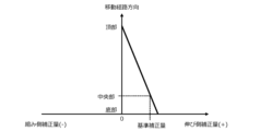
- the correction processing unit 45 calculates a linear correction amount by linearly changing the correction reference amount in response to the position in the movement path direction, starting from the top, which is a fixed point of the APS tape 14.
- FIG. 12 is a diagram showing the linear correction amount corresponding to the position in the movement path direction. As shown in this figure, the linear correction amount changes linearly in response to the position in the movement path direction, so that the linear correction amount becomes the correction reference amount at the center of the correction plate 20 and becomes zero at the top of the APS tape 14.
- the correction processing unit 45 records the calculated linear correction amount in the car position table.
- the correction processing unit 45 identifies and adds the corresponding linear correction amount to the APS data read by the APS 12 according to the relationship between the APS learning data and the linear correction amount recorded in the cage position table, and calculates the current absolute position of the cage 8.
- the above correction process makes it possible to associate accurate absolute position information with the car position of car 8 even if the APS tape 14 expands or contracts due to building deformation or temperature changes. This makes it possible to always detect the absolute position of car 8 with high accuracy in the car position calculation process.
- the degenerate operation control unit 46 is a functional block for performing degenerate operation.
- the degenerate operation control unit 46 cuts off the power supply to the hoist 3 by cutting off the safety circuit using the safety circuit breaker unit 38, and temporarily stops the car. Then, just before instructing the elevator control device 6 to perform degenerate operation, the degenerate operation control unit 46 reconnects the safety circuit using the safety circuit breaker unit 38 and resumes the power supply to the hoist 3.
- the degenerate operation control unit 46 commands the elevator control device 6 to perform degenerate operation, the elevator control device 6 moves the car 8 at a low speed toward the nearest evacuation floor.
- Figures 13 and 14 are flowcharts of routines executed in the elevator system.
- the routines shown in Figures 13 and 14 are executed in the processing unit 30 of the safety control device 10, for example, when a certain time has elapsed since the previous update of the correction reference amount.
- step S110 it is determined whether the correction sensor 22 installed on the car 8 has entered the correction plate 20 based on the correction sensor signal of the correction sensor 22. If the determination is not true, step S110 is executed again, and if the determination is true, the process proceeds to step S112.
- step S112 the entry position and entry speed at the time of entry are recorded in the correction plate position table.
- the lower end entry position B1 and the lower end entry speed Vb1 are recorded in the correction plate position table.
- the upper end entry position A1 and the upper end entry speed Va1 are recorded in the correction plate position table.
- step S114 it is determined whether the entry position and entry speed at the time of entry in the opposite direction to the entry position and entry speed recorded in step S112 of this routine are recorded in the correction plate position table. If the determination is not true, it is determined that the APS calculated position CP of the center of the correction plate 20 cannot be calculated, and the process proceeds to step S118. On the other hand, if the determination is true, it is determined that the APS calculated position CP can be calculated, and the process proceeds to step S116.
- step S116 the APS calculated position CP and the correction reference amount (A) corresponding to the APS calculated position CP are calculated.
- step S118 it is determined whether the exit position and exit speed at the time of exit in the opposite direction to the entry direction corresponding to the entry position and entry speed recorded in the immediately preceding step S112 are recorded in the correction plate position table. If the determination is not true, the process proceeds to step S124, and if the determination is true, the process proceeds to step S120.
- step S120 if an entry during an upward movement of the car 8 is recognized in step S110 of this routine, the APS calculation position LP of the lower end of the correction plate 20 is calculated. Alternatively, if an entry during a downward movement of the car 8 is recognized in step S110 of this routine, the APS calculation position UP of the upper end of the correction plate 20 is calculated. In addition, a correction reference amount (B) corresponding to the calculated APS calculation position LP or APS calculation position UP is calculated.
- step S122 the processing proceeds to step S122.
- step S122 the correction reference amount is updated to the correction reference amount (A) calculated in step S116 or the correction reference amount (B) calculated in step S120, whichever has the smaller absolute value.
- step S124 it is determined whether the correction sensor 22 installed on the car 8 has escaped from the correction plate 20 based on the correction sensor signal of the correction sensor 22. If the determination is not true, step S124 is executed again, and if the determination is true, the process proceeds to step S126.
- step S126 if the escape occurred while the car 8 was ascending, the upper end escape position A2 and the upper end escape velocity Va2 are recorded in the correction plate position table. Alternatively, if the escape occurred while the car 8 was descending, the lower end escape position B2 and the lower end escape velocity Vb2 are recorded in the correction plate position table.
- step S128 the processing proceeds to step S128.
- step S1208 it is determined whether the exit direction in step S126 is the opposite direction to the entry direction in step S110. If the determination is negative, the processing of this routine ends, and if the determination is positive, the processing proceeds to step S130.
- step S130 if an entry during an upward movement of the car 8 is recognized in step S110 of this routine, the APS calculation position UP of the upper end of the correction plate 20 is calculated. Alternatively, if an entry during a downward movement of the car 8 is recognized in step S110 of this routine, the APS calculation position LP of the lower end of the correction plate 20 is calculated. In addition, a correction reference amount (C) corresponding to the calculated APS calculation position LP or APS calculation position UP is calculated.
- step S132 the processing proceeds to step S132.
- step S132 the correction reference amount is updated to the smallest absolute value among the correction reference amount (A) calculated in step S116, the correction reference amount (B) calculated in step S120, and the correction reference amount (C) calculated in step S130.
- the processing of step S132 proceeds to step S134.
- step S134 a linear correction amount is calculated based on the correction reference amount.
- the linear correction amount is added to the detected APS data to correct the absolute position of car 8.
- the elevator system of the first embodiment may employ the following modified aspects. These modified aspects may also be applied to elevator systems of other embodiments described later.
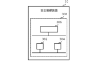
- Safety control device 10 Fig. 15 is a diagram showing a modified example of hardware resources in the processing unit 30 of the safety controller 10.
- the safety controller 10 includes a processing circuit 308 including, for example, a processor 302, a memory 304, and dedicated hardware 306.
- Fig. 15 shows an example in which some of the functions of the safety controller 10 are realized by the dedicated hardware 306. All of the functions of the safety controller 10 may be realized by the dedicated hardware 306.
- the dedicated hardware 306 a single circuit, a composite circuit, a programmed processor, a parallel programmed processor, an ASIC, an FPGA, or a combination thereof can be adopted.
- the safety control device 10 and the elevator control device 6 may be configured as a single control device.
- correction processing unit 45 The correction starting point when calculating the linear correction amount in the correction process is not limited to the top of the APS tape 14. In other words, when an APS tape with the bottom as a fixed point is used, the bottom of the APS tape 14 may be the correction starting point.
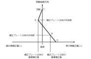
- FIG. 16 is a diagram showing an example of calculating a linear correction amount corresponding to the position in the moving path direction using multiple correction reference amounts.
- the linear correction amount between the top of the APS tape 14 and the center of the correction plate 20A becomes the correction reference amount of the correction plate 20A at the center of the correction plate 20A, and changes linearly corresponding to the position in the moving path direction so as to be zero at the top of the APS tape 14.
- the linear correction amount between the center of the correction plate 20A and the center of the correction plate 20B becomes the correction reference amount of the correction plate 20A at the center of the correction plate 20A, and changes linearly corresponding to the position in the moving path direction so as to be the correction reference amount of the correction plate 20B at the center of the correction plate 20B.
- This type of correction process increases the likelihood that the APS learning data can be appropriately corrected when the degree of expansion and contraction of the APS tape 14 varies depending on the position in the movement path direction.
- the APS tape 14 tends to expand and contract more as the temperature fluctuations become greater. For this reason, for example, in a hoistway that has a see-through area where the outside can be seen from inside the hoistway, the temperature fluctuations in the see-through area are greater than in other areas, and so there is a risk that the degree of expansion and contraction of the APS tape 14 in the see-through area will be greater than the degree of expansion and contraction in other areas. Therefore, in such special hoistways, it is preferable to install correction plates 20 in the temperature fluctuation area where the temperature fluctuations are greater than in other areas, and in the other areas.
- the method of calculating the APS detected speed is not limited to the method of calculating from the amount of change in the APS data over time. That is, since the APS sensor 16 is installed on the upper part of the car 8, the APS detected speed can also be calculated using the encoder of the hoist 3.
- Embodiment 2 In the second embodiment, differences from the example disclosed in the first embodiment will be described in particular detail. For features not described in the second embodiment, any of the features of the example disclosed in the first embodiment may be adopted.
- the elevator system of the second embodiment is characterized by the installation location of the correction plate 20 and the degenerate operation using the correction plate 20.
- the correction plate 20 which also functions as an evacuation floor plate, is installed at the evacuation floor position detected by the correction sensor 22 when the car 8 stops at the evacuation floor.
- the degenerate operation control unit 46 is a functional block for performing degenerate operation.
- the degenerate operation here includes emergency stopping of the car 8 and low-speed operation to the nearest evacuation floor. Specifically, degenerate operation is performed when an abnormality occurs in the APS 12, or when an error occurs in the acquisition process or correction process, etc.
- the correction sensor 22 detects the correction plate 20 installed at the evacuation floor position, thereby detecting that the car 8 has moved to the evacuation floor. This type of operation makes it possible to perform degenerate operation to move the car 8 to the evacuation floor, even if an abnormality occurs in the APS 12.
- Fig. 17 is a flowchart of a routine executed in the elevator system of the second embodiment.
- the routine shown in Fig. 17 is executed in the processing unit 30 of the safety control device 10.
- step S200 it is determined whether an abnormality in APS 12 has been detected.
- abnormalities in APS 12 here include a loss of communication from APS 12, the occurrence of a communication error, or a signal that is different from normal being sent from APS 12. If the determination is not true, the process proceeds to step S202, and if the determination is true, the process proceeds to step S204.
- step S202 it is determined whether or not there is an error. Specifically, it is determined that there is an error if the correction sensor 22 detects the correction plate 20 and the cage 8 is not near the correction plate 20. It is also determined that there is an error if the correction sensor 22 does not detect the correction plate 20 and the cage 8 is near the correction plate 20. It is also determined that there is an error if the correction reference amount calculated in the correction process is greater than a predetermined abnormality determination threshold. As a result, if the determination is not made, the process returns to the beginning of this routine, and if the determination is made, the process proceeds to step S204.
- step 204 the safety circuit (not shown) is cut off by the safety circuit cutoff unit 38, which stops the hoist 3. This brings the car 8 to an emergency stop.
- step S206 the process proceeds to step S206.
- step S206 the safety circuit is reconnected by the safety circuit breaker 38, and an operation command is sent from the safety control device 30 to the elevator control device 6 to operate the car 8 at a low speed in the direction of the nearest evacuation floor. This causes the car 8 to move at a low speed in the direction of the nearest evacuation floor.
- step S208 the processing proceeds to step S208.
- step S208 it is determined whether the correction sensor 22 has detected the correction plate 20 installed at the evacuation floor position. If the determination is negative, the process proceeds to step S210, and if the determination is positive, the process proceeds to step S214.
- step S210 it is determined whether car 8 has traveled a certain distance or more, or whether a predetermined grace period has expired.
- the certain distance here is set to the distance that car 8 can reach from the emergency stop position to the nearest evacuation floor.
- the travel distance of car 8 can be counted using APS 12, and if an abnormality in APS 12 is detected, the encoder of the hoist 3 is used.
- the process proceeds to step S212, and if the determination is negative, the process returns to step S208 again. In other words, the determination in step S208 is repeatedly executed until the determination in step S220 is positive.
- step S212 the safety circuit is interrupted by the safety circuit interruption unit 38, thereby stopping the hoist 3. This stops the car 8.
- the processing of step 212 proceeds to step S216.
- step S214 after car 8 has stopped, the doors are opened and closed to allow passengers to disembark at the evacuation floor.
- step S216 elevator service is stopped and this routine is terminated.
- the speed command value may be obtained from the elevator control device 6. In either case, under normal circumstances, the speed obtained from the APS 12 is compared with the encoder value or the speed command value to confirm the accuracy of the encoder value or the speed command value.
Landscapes
- Indicating And Signalling Devices For Elevators (AREA)
- Maintenance And Inspection Apparatuses For Elevators (AREA)
Abstract
設置性及び据付性を向上させた構成で絶対位置測位システムの誤差を補正することにより、かごの絶対位置を高精度に検出する。 かごの移動経路方向の絶対位置に対応した絶対位置情報を検出する絶対位置測位システム(APS)を備えるエレベーターシステムは、昇降路内に固定設置された被検出体と、かごに取り付けられた被検出体検出装置と、を備える。記憶装置には、移動経路方向における被検出体の基準位置に対応する絶対位置として事前学習された学習値が予め記憶されている。制御装置は、かごの走行中に被検出体検出装置が被検出体の端部を検出したときの絶対位置情報及びかごの移動速度情報をそれぞれ取得し、取得した情報に基づいて、基準位置の絶対位置算出値を算出し、記憶装置に記憶されている学習値と算出された絶対位置算出値との比較に基づいて、APSにより検出される絶対位置情報を補正する。
Description
本開示は、エレベーターのかごの絶対位置を検出する絶対位置測位システムを備えたエレベーターシステムに関する。
特許文献1には、かごの昇降経路に沿って昇降路に磁気テープを張設し、かごには磁気テープを検出する磁気センサを設置する構成のかご位置検出装置を調整する方法に関する技術が開示されている。この技術では、かごが各階乗場に着床したことを検出するジャストレベルセンサを設けている。ジャストレベルセンサは、各階の乗場の敷居に設けられた反射板と、かごに設けた光電センサとを有し、かごが各乗場に正確に着床する位置に来たときに反射板を検出するようになっている。そして、調整作業において、昇降路内のかごを移動させてジャストレベルセンサが作動したときの磁気テープ上の位置をジャストレベルとして記録する。
特許文献1のかご位置検出装置のように、昇降路全長に設置されたテープの情報をかごに設置されたセンサで読み取ることでかごの絶対位置を検出する絶対位置測位システム(APS)を備えたエレベーターでは、建物変形又は温度変化に伴うテープの伸縮によってかご位置の測位がずれるという課題がある。特許文献1の技術では、ジャストレベルセンサによって当該課題を解決することを開示している。しかしながら、特許文献1の技術では、ジャストレベルセンサの反射板を各階の乗場の敷居に設置する必要があり、装置の設置性及び据付性に課題がある。
本開示は、上述のような課題を解決するためになされたもので、設置性及び据付性を向上させた構成で絶対位置測位システムの誤差を補正することにより、かごの絶対位置を高精度に検出することのできるエレベーターシステムを提供することを目的とする。
本開示のエレベーターシステムは、昇降路内を走行するかごの移動経路方向の絶対位置に対応した絶対位置情報を検出する絶対位置測位システムと、検出した絶対位置情報に基づいてかごの運転を制御するエレベーター制御装置と、を備えるエレベーターシステムに適用される。エレベーターシステムは、昇降路内に固定設置された被検出体と、かごに取り付けられ、被検出体を検出する被検出体検出装置と、移動経路方向における被検出体の基準位置に対応する絶対位置として事前学習された学習値を予め記憶した記憶装置と、制御装置と、を備える。制御装置は、かごが上昇方向と下降方向とをそれぞれ任意の速度で走行して被検出体検出装置が被検出体の端部を検出した端部検出時に絶対位置測位システムにより検出された絶対位置情報及び端部検出時のかごの移動速度情報をそれぞれ取得する取得処理部と、取得処理部によって取得された絶対位置情報と移動速度情報とに基づいて、基準位置の絶対位置算出値を算出する算出処理部と、学習値と絶対位置算出値との比較に基づいて、絶対位置測位システムにより検出される絶対位置情報を補正する補正処理部と、を備える。
本開示によれば、設置性及び据付性を向上させた構成で絶対位置測位システムの誤差を補正することにより、かごの絶対位置を高精度に検出することのできるエレベーターシステムを提供することが可能となる。
以下、図面を参照して実施の形態について説明する。なお、各図において共通する要素には、同一の符号を付して、重複する説明を省略する。
実施の形態1.
1-1.実施の形態1のエレベーターシステムの概略構成
図1は、実施の形態1に係るエレベーターシステムが備えるエレベーターの概略構成図である。実施の形態1に係るエレベーターシステム100のエレベーターは、複数の階床を有する建物などからなる施設に設置されている。施設において、エレベーターの昇降路2が設けられる。昇降路2は、複数の階床4にわたる上下方向に長い空間である。
1-1.実施の形態1のエレベーターシステムの概略構成
図1は、実施の形態1に係るエレベーターシステムが備えるエレベーターの概略構成図である。実施の形態1に係るエレベーターシステム100のエレベーターは、複数の階床を有する建物などからなる施設に設置されている。施設において、エレベーターの昇降路2が設けられる。昇降路2は、複数の階床4にわたる上下方向に長い空間である。
エレベーターは、主要な構成として、巻上機3と、エレベーター制御装置6と、かご8と、を備える。かご8は、昇降路2を移動経路方向である上下方向に走行することで、内部に乗車している利用者などを複数の階床4の間で輸送する装置である。かご8の走行は、昇降路2の上部に設置された巻上機3によって行われる。エレベーター制御装置6は、エレベーターの動作を制御する制御盤に相当する。エレベーター制御装置6によって制御されるエレベーターの動作は、例えば扉の開閉、登録される呼びの管理、および呼びに応答するかご8の走行などを含む。
エレベーターは、絶対位置測位システム12を備える。絶対位置測位システムは、以下「APS」とも呼ばれる。APS12は、かご8の昇降路2におけるかご8の移動経路方向の位置に対応した絶対位置情報を検出する絶対位置検出装置として機能するシステムである。APS12は、APSテープ14と、APSセンサ16と、を備える。
APSテープ14は、昇降路2内の移動経路方向に沿って設けられた長尺体である。典型的には、APSテープ14は、昇降路2内の移動経路方向の位置に対応して絶対位置情報が連続的に設定されている。絶対位置情報は、APSテープ14の上下方向に頂部から底部にかけて、磁気式特性或いは光学式特定を連続的に異ならせることによって設定された情報である。APSテープ14から読み取られる絶対位置情報は、以下「APSデータ」とも呼ばれる。
APSセンサ16は、APSテープ14からAPSデータを読み取るためのセンサである。APSセンサ16は、かご8の上において、APSテープ14に向かい合う位置に設置される。APSセンサ16の検出方式は、例えば磁気方式、光学方式等、APSテープ14からAPSデータを読み取り可能な方式が採用される。APSセンサ16によって検出されたAPSデータは、後述する安全制御装置10へシリアル伝送される。
さらに、エレベーターは、1又は複数の補正用プレート20と、補正センサ22と、を備える。補正用プレート20は、昇降路2に固定設置される矩形金属性のプレートである。補正用プレート20は、以下「被検出体」とも呼ばれる。補正用プレート20の設置場所及び設置数量に限定はない。例えば、補正用プレート20は、昇降路2において移動経路方向に沿って数十メートル間隔で複数個設置してもよい。なお、補正用プレート20の設置は、階床4に対応した場所でなくてもよい。ただし、実施の形態2において後述する縮退運転において利用される避難階用プレートとしての機能を兼ねる補正用プレート20は、避難階の階床に対応した避難階位置に設置される。
補正センサ22は、補正用プレート20の端部を検出するセンサ装置であり、「被検出体検出装置」とも呼ばれる。補正センサ22は、かご8の上において補正用プレート20と向かい合う位置に設置される。典型的には、補正センサ22は、かご8の上昇時において、補正用プレート20の下端部からの進入及び上端部からの脱出を検出する。また、補正センサ22は、かご8の下降時において、補正用プレート20の上端部からの進入及び下端部からの脱出を検出する。検出した補正センサ信号は、安全制御装置10へパラレル伝送される。
安全制御装置10は、エレベーターの安全制御を担う制御装置である。図2は、安全制御装置が備える機能ブロックを説明するための図である。図2に示すように、安全制御装置10は、その機能として処理部30と、APSデータ受信部32と、補正センサ信号入力部34と、学習データ入力部36と、安全回路遮断部38と、記憶装置40と、を備える。
処理部30は、プロセッサ302と、メモリ304と、を備える。プロセッサ302は、各種処理を実行する。プロセッサ302は、例えばマイクロコンピュータである。メモリ304には、各種データが格納される。メモリ304としては、揮発性メモリ、不揮発性メモリ、等が例示される。メモリ304には、各種プログラムが記憶されている。プロセッサ302が各種プログラムを実行することにより、処理部30の機能が実現される。処理部30の機能については説明を後述する。
APSデータ受信部32は、APSセンサからシリアル伝送されるAPSデータを受信するための機能ブロックである。受信したAPSデータは、処理部30のメモリに一時的に格納される。
補正センサ信号入力部34は、補正センサ22からパラレル伝送される補正センサ信号の入力を受け付けるための機能ブロックである。受信した補正センサ信号は、処理部30のメモリに一時的に格納される。
学習データ入力部36は、後述する学習データ入力端末50からシリアル伝送される学習データの入力を受け付けるための機能ブロックである。受信した学習データは、処理部30のメモリに一時的に格納される。
安全回路遮断部38は、APS12の異常等によってかご8の絶対位置を検出できない場合等に、図示しない安全回路を遮断することで巻上機3の電源供給を遮断し、かごを停止させるための機能ブロックである。また、安全制御装置10からエレベーター制御装置6へ縮退運転を指令する場合、安全回路遮断部38は、縮退運転の指令の直前に安全回路を再接続し、巻上機3への電源供給を再開させる機能も備える。なお、ここでの縮退運転とは、APS12に異常が発生した場合に、かご8を緊急停止させた後、最寄りの避難階へ向かってかご8を低速移動させる運転である。縮退運転の具体的な動作については詳細を後述する。
記憶装置40は、後述するかご位置テーブルと補正用プレート位置テーブルとが格納された装置である。記憶装置40は、揮発性メモリ、不揮発性メモリ、等が例示される。なお、記憶装置40は、処理部30の一部として構成されていてもよい。例えば、記憶装置40は、メモリ304であってもよい。
1-2.処理部30の機能
図3は、処理部によって実現される機能を示す機能ブロック図である。この図に示すように、処理部30は、各種処理を実行する機能ブロックとして、事前学習処理部41と、取得処理部43と、補正用プレート位置算出処理部44と、補正処理部45と、縮退運転制御部46と、を備える。以下、これらの機能ブロックでの具体的処理について説明する。
図3は、処理部によって実現される機能を示す機能ブロック図である。この図に示すように、処理部30は、各種処理を実行する機能ブロックとして、事前学習処理部41と、取得処理部43と、補正用プレート位置算出処理部44と、補正処理部45と、縮退運転制御部46と、を備える。以下、これらの機能ブロックでの具体的処理について説明する。
1-2-1.事前学習処理部41
事前学習処理部41は、各階床4におけるかご8の停止位置及び補正用プレート20の位置に対応する絶対位置情報を学習してかご位置テーブルを更新するための機能ブロックである。この処理は、以下「事前学習処理」と呼ばれる。事前学習処理は、エレベーターの設置後の初回時だけでなく、定期的に実行されることとしてもよい。図4は、記憶装置に格納されているかご位置テーブルの一例を示す図である。この図に示すように、かご位置テーブルは、かご8の位置に対応する絶対位置を学習したAPS学習データが記憶されたテーブルである。事前学習処理において、事前学習処理部41は、保守員によって手入力されたかご8の停止位置に対応するAPS学習データを受け付けてかご位置テーブルを更新する。保守員による手入力には学習データ入力端末50が利用される。学習データ入力端末50は、事前学習処理において安全制御装置10に接続されて使用される外付けの入力端末である。図5は、学習データ入力端末の入力画面の一例を示す図である。この図に示す例では、入力画面には、現在学習値表示部51と、入力数値表示部52と、オフセット値入力ボタン53と、現在階表示部54と、階修正ボタン55と、決定ボタン56と、クリアボタン57と、APSデータ表示部58と、テンキーボタン59と、を備える。なお、学習データ入力端末50の入力画面において、APSデータ表示部58及びテンキーボタン59は必須ではない。
事前学習処理部41は、各階床4におけるかご8の停止位置及び補正用プレート20の位置に対応する絶対位置情報を学習してかご位置テーブルを更新するための機能ブロックである。この処理は、以下「事前学習処理」と呼ばれる。事前学習処理は、エレベーターの設置後の初回時だけでなく、定期的に実行されることとしてもよい。図4は、記憶装置に格納されているかご位置テーブルの一例を示す図である。この図に示すように、かご位置テーブルは、かご8の位置に対応する絶対位置を学習したAPS学習データが記憶されたテーブルである。事前学習処理において、事前学習処理部41は、保守員によって手入力されたかご8の停止位置に対応するAPS学習データを受け付けてかご位置テーブルを更新する。保守員による手入力には学習データ入力端末50が利用される。学習データ入力端末50は、事前学習処理において安全制御装置10に接続されて使用される外付けの入力端末である。図5は、学習データ入力端末の入力画面の一例を示す図である。この図に示す例では、入力画面には、現在学習値表示部51と、入力数値表示部52と、オフセット値入力ボタン53と、現在階表示部54と、階修正ボタン55と、決定ボタン56と、クリアボタン57と、APSデータ表示部58と、テンキーボタン59と、を備える。なお、学習データ入力端末50の入力画面において、APSデータ表示部58及びテンキーボタン59は必須ではない。
図6は、事前学習処理において保守員による手入力によりかご位置テーブルを更新する手順を説明するためのフローチャートである。事前学習処理のステップS100において、先ずエレベーターのかご8を事前の階床設定値に従い各階に停止させる。ステップS102において、事前学習処理部41は、保守員による手入力された入力データを受け付ける。現在階表示部54には入力対象の階床が表示されており、階修正ボタン55によって入力対象の階床を修正することができる。現在学習値表示部51には、かご位置テーブルに記憶されている現在のAPS学習データが表示されている。保守員は、例えば目視によってかご8の絶対位置を確認し、かご床面の階床位置からのずれを、登録されている現在のAPS学習データに対するオフセット値として、オフセット値入力ボタン53を操作してミリ単位で入力する。入力数値表示部52には、保守員によって入力されたオフセット値が表示される。入力されたオフセット値をクリアする際にはクリアボタン57が押される。入力されたオフセット値を登録する際には決定ボタン56が押される。なお、保守員は、テンキーボタン59を用いてオフセット値を直接入力してもよい。また、保守員は、手動運転でかご床面と階床位置をあわせ、APSデータ表示部58に表示されている現在のAPSデータの検出値を参照して、学習値との差分をオフセット値として入力してもよい。
ステップS104において、事前学習処理部41は、保守員によって入力されたオフセット値の入力データに基づいて、かご位置テーブルのAPS学習データを更新する。このような処理が各階床4においてそれぞれ実行されることにより、かご位置テーブルにおける各階床4のAPS学習データが更新される。
なお、最上階の更に上の頂部及び最下階である1階の更に下の底部は、かご8を移動範囲外であることがある。このような場合、事前学習処理において、頂部及び底部に対応するAPS学習データに、予め定められた固定値或いは最上階及び最下階から算出される算出値を入力してもよい。
また、事前学習処理において、事前学習処理部41は、かご8の走行中に補正用プレート20の基準位置としての上下方向の中央部、上端部、及び下端部に対応する絶対位置を算出する。ここでは、エレベーターを往復走行させて後述する取得処理及び補正用プレート位置算出処理と同様の演算処理を行うことにより、中央部、上端部、及び下端部に対応する絶対位置を算出することができる。事前学習処理部41は、算出した絶対位置に基づいてかご位置テーブルのAPS学習データを更新する。
1-2-2.取得処理部43
取得処理部43は、かご8が上昇方向と下降方向とをそれぞれ任意の速度で走行して補正センサ22が補正用プレート20の端部を検出した端部検出時のAPS検出位置及びAPS検出速度を取得するための機能ブロックである。この処理は、以下「取得処理」と呼ばれる。ここでの「APS検出位置」は、端部検出時の絶対位置情報であり、より具体的にはAPS12により算出されるAPSデータである。また、「APS検出速度」は、APSセンサ16が設置されたかご8の端部検出時における移動速度情報である。APS検出速度は、例えば、APSデータの時間変化量から算出することができる。
取得処理部43は、かご8が上昇方向と下降方向とをそれぞれ任意の速度で走行して補正センサ22が補正用プレート20の端部を検出した端部検出時のAPS検出位置及びAPS検出速度を取得するための機能ブロックである。この処理は、以下「取得処理」と呼ばれる。ここでの「APS検出位置」は、端部検出時の絶対位置情報であり、より具体的にはAPS12により算出されるAPSデータである。また、「APS検出速度」は、APSセンサ16が設置されたかご8の端部検出時における移動速度情報である。APS検出速度は、例えば、APSデータの時間変化量から算出することができる。
取得処理において、取得処理部43は、かご8が上昇方向に走行して補正用プレート20の下端部を検出したときの下端進入位置B1及び下端進入速度Vb1、かご8が上昇方向に走行して補正用プレート20の上端部を検出したときの上端脱出位置A2及び上端脱出速度Va2、かご8が下降方向に走行して補正用プレート20の下端部を検出したときの下端脱出位置B2及び下端脱出速度Vb2、及びかご8が下降方向に走行して補正用プレート20の上端部を検出したときの上端進入位置A1及び上端進入速度Va1を、それぞれAPS検出位置及びAPS検出速度として取得する。また、この際、APS検出位置及びAPS検出速度は、APSデータ検出したデータ検出時間に対応づけてそれぞれ取得される。
図7は、記憶装置に格納されている補正用プレート位置テーブルの一例を示す図である。取得処理部43は、取得したデータを補正用プレート位置テーブルに記録する。なお、データ検出時間は、タイムスタンプとして、各データに対応づけて記録する。また、取得処理部43は、古いデータを利用することを回避するために、予め定められた有効期限よりも前のタイムスタンプに対応付けられているデータを無効化する。有効期限は、例えば1日である。なお、昇降路2に複数の補正用プレート20が設置されている場合、それぞれの補正用プレート20に対して上述した取得処理が実行され、それぞれのプレートNo.に対応づけて補正用プレート位置テーブルに記録される。
補正用プレート20が最上階付近に設置されている場合、かご8上昇方向に走行したときに補正用プレート20の上端部が検出されないことがある。同様に、補正用プレート20が最下階付近に設置されている場合、かご8下降方向に走行したときに補正用プレート20の下端部が検出されないことがある。このような場合、補正用プレート位置テーブルには、取得されなかった値に無効値が記録される。
なお、取得処理は、エレベーター利用者を乗車させる通常運転中に実行してもよいし、利用者の乗車を制限する保守運転中に実行してもよい。なお、保守運転中に取得処理を実行する場合、通常運転中の移動速度よりも低速でかご8を走行させてもよい。これにより、検出精度の向上及び補正用プレート20の小型化を図ることができる。取得処理において取得されたAPS検出位置及びAPS検出速度は、後述する補正用プレート位置算出処理において利用される。
1-2-3.補正用プレート位置算出処理部44
補正用プレート位置算出処理部44は、取得処理において取得されたAPS検出位置及びAPS検出速度を用いて、補正用プレート20の基準位置としての上端部、下端部及び中央部の位置を算出するための機能ブロックである。この処理は、以下「補正用プレート位置算出処理」と呼ばれる。また、補正用プレート位置算出処理によって算出される補正用プレート20の絶対位置算出値は、以下「APS算出位置」と呼ばれる。
補正用プレート位置算出処理部44は、取得処理において取得されたAPS検出位置及びAPS検出速度を用いて、補正用プレート20の基準位置としての上端部、下端部及び中央部の位置を算出するための機能ブロックである。この処理は、以下「補正用プレート位置算出処理」と呼ばれる。また、補正用プレート位置算出処理によって算出される補正用プレート20の絶対位置算出値は、以下「APS算出位置」と呼ばれる。
図8は、補正用プレート位置算出処理において補正用プレートの中央部のAPS算出位置を算出する方法を説明するための図である。この図に示すように、補正用プレート20の移動経路方向の寸法をLとした場合、補正用プレート20の移動経路方向の中央部のAPS算出位置CPは、上端進入位置A1、上端進入速度Va1、下端進入位置B1、及び下端進入速度Vb1を用いた次式(1)により算出される。なお、上端進入位置A1、上端進入速度Va1、下端進入位置B1、及び下端進入速度Vb1は、補正用プレート位置テーブルに記録されている値が利用される。補正用プレート位置算出処理部44は、算出した中央部のAPS算出位置CPを補正用プレート位置テーブルに記録する。
CP=B1+(A1-B1-L)×Vb1/(Va1+Vb1)+L/2・・・(1)
図9は、補正用プレート位置算出処理において補正用プレートの上端部のAPS算出位置を算出する方法を説明するための図である。この図に示すように、補正用プレート20の移動経路方向の上端部のAPS算出位置UPは、上端進入位置A1、上端進入速度Va1、上端脱出位置A2、及び上端脱出速度Va2を用いた次式(2)により算出される。なお、上端進入位置A1、上端進入速度Va1、上端脱出位置A2、及び上端脱出速度Va2は、補正用プレート位置テーブルに記録されている値が利用される。補正用プレート位置算出処理部44は、算出した上端部のAPS算出位置UPを補正用プレート位置テーブルに記録する。
UP=A2+(A1-A2)×Va2/(Va1+Va2) ・・・(2)
図10は、補正用プレート位置算出処理において補正用プレートの下端部のAPS算出位置を算出する方法を説明するための図である。この図に示すように、補正用プレート20の移動経路方向の下端部のAPS算出位置LPは、下端進入位置B1、下端進入速度Vb1、下端脱出位置B2、及び下端脱出速度Vb2を用いた次式(3)により算出される。なお、下端進入位置B1、下端進入速度Vb1、下端脱出位置B2、及び下端脱出速度Vb2は、補正用プレート位置テーブルに記録されている値が利用される。補正用プレート位置算出処理部44は、算出した下端部のAPS算出位置LPを補正用プレート位置テーブルに記録する。
LP=B1+(B2-B1)×Vb1/(Vb1+Vb2) ・・・(3)
APSセンサ16において検出されたAPSデータは、シリアル伝送によって安全制御装置10へ送られるため、データ遅延が発生し、走行速度に依存したずれが発生する。上式(1)、(2)又は(3)によれば、補正センサ22が補正用プレート20の端部を検出したときのAPS検出速度を考慮して補正用プレート20のAPS算出位置が算出されるので、シリアル伝送に起因するデータ遅延の影響を排除することができる。このため、取得処理において任意の速度でかご8を走行させてAPS検出位置及びAPS検出速度を取得したとしても、APS算出位置を高精度に算出することができる。
また、上述したように、補正用プレート20が最上階付近に設置されていて、補正用プレート20の上端部が補正センサ22によって検出されないことがある、このような場合、上端部のAPS算出位置UP及び中央部のAPS算出位置CPを算出することができないが、少なくとも下端部のAPS算出位置LPを算出することができるので、算出されたAPS算出位置LPを用いて、後述の補正処理を行うことができる。同様に、補正用プレート20の下端部が補正センサ22によって検出されない場合であっても、少なくとも上端部のAPS算出位置UPを算出することができるので、算出されたAPS算出位置UPを用いて、後述の補正処理を行うことができる。このように、補正用プレート位置算出処理部44は、補正用プレート20の設置位置に応じて、中央部のAPS算出位置CP、上端部のAPS算出位置UP、及び下端部のAPS算出位置LPのうちの少なくとも1つを算出可能な構成を備えていればよい。
1-2-4.補正処理部45
補正処理部45は、事前学習処理において事前学習された学習値としてのAPS学習データを補正する補正処理を実行するための機能ブロックである。図11は、補正処理においてAPS学習データを補正する方法を説明するための図である。補正処理において、補正用プレート20の上端部、下端部、及び中央部のそれぞれにおいて、APS学習データに対するAPS算出位置の差分値を演算する。そして、例えば、算出された差分値のうちの最小値を補正基準量として特定する。図11では、補正用プレート20の中央部における差分値が補正基準量として特定された場合を例示している。
補正処理部45は、事前学習処理において事前学習された学習値としてのAPS学習データを補正する補正処理を実行するための機能ブロックである。図11は、補正処理においてAPS学習データを補正する方法を説明するための図である。補正処理において、補正用プレート20の上端部、下端部、及び中央部のそれぞれにおいて、APS学習データに対するAPS算出位置の差分値を演算する。そして、例えば、算出された差分値のうちの最小値を補正基準量として特定する。図11では、補正用プレート20の中央部における差分値が補正基準量として特定された場合を例示している。
補正処理部45は、APSテープ14の固定点である頂部を補正起点として、移動経路方向の位置に対応して補正基準量を線形に変化させた線形補正量を算出する。図12は、移動経路方向の位置に対応した線形補正量を示す図である。この図に示すように、線形補正量は、補正用プレート20の中央部において補正基準量となり、APSテープ14の頂部においてゼロとなるように、移動経路方向の位置に対応して線形に変化している。補正処理部45は、算出した線形補正量をかご位置テーブルに記録する。
補正処理部45は、かご位置テーブルに記録されているAPS学習データと線形補正量との関係に従い、APS12が読み取ったAPSデータに、対応する線形補正量を特定して加算し、かご8の現在の絶対位置を算出する。
以上のような補正処理によれば、建物変形又は温度変化に伴うAPSテープ14の伸縮が発生した場合であっても、かご8のかご位置に対して正確な絶対位置情報を対応付けることができる。これにより、かご位置算出処理において、かご8の絶対位置を常に高精度に検出することが可能となる。
縮退運転制御部46は、縮退運転を行うための機能ブロックである。縮退運転制御部46は、APS12の異常等によってかご8の絶対位置を検出できない場合等に、安全回路遮断部38によって安全回路を遮断することで巻上機3の電源供給を遮断し、かごを一旦停止させる。そして、縮退運転制御部46は、エレベーター制御装置6へ縮退運転を指令する直前に、安全回路遮断部38によって安全回路を再接続し、巻上機3への電源供給を再開させる。縮退運転制御部46からエレベーター制御装置6へ縮退運転が指令されると、エレベーター制御装置6は、最寄りの避難階へ向かってかご8を低速移動させる。
1-3.実施の形態1のエレベーターシステムによる具体的な処理例
次に、フローチャートを参照して、エレベーターシステムにおいて実行される取得処理、補正用プレート位置算出処理、及び補正処理の具体的な処理例を説明する。図13及び図14は、エレベーターシステムにおいて実行されるルーチンのフローチャートである。図13及び図14に示すルーチンは、例えば前回の補正基準量の更新から一定時間経過した場合に、安全制御装置10の処理部30において実行される。
次に、フローチャートを参照して、エレベーターシステムにおいて実行される取得処理、補正用プレート位置算出処理、及び補正処理の具体的な処理例を説明する。図13及び図14は、エレベーターシステムにおいて実行されるルーチンのフローチャートである。図13及び図14に示すルーチンは、例えば前回の補正基準量の更新から一定時間経過した場合に、安全制御装置10の処理部30において実行される。
ステップS110において、補正センサ22の補正センサ信号に基づいて、かご8の上に設置された補正センサ22が補正用プレート20に進入したかが判定される。その結果、判定が成立しない場合、本ステップS110が再度実行され、判定が成立した場合、処理はステップS112に進む。
ステップS112において、進入時の進入位置及び進入速度が補正用プレート位置テーブルに記録される。典型的には、かご8の上昇時の進入である場合、下端進入位置B1及び下端進入速度Vb1が補正用プレート位置テーブルに記録される。或いは、かご8の下降時の進入である場合、上端進入位置A1及び上端進入速度Va1が補正用プレート位置テーブルに記録される。ステップS112の処理が完了すると、処理はステップS114に進む。
ステップS114において、本ルーチンのステップS112において記録された進入位置及び進入速度に対応する進入方向と逆方向の進入時の進入位置及び進入速度が補正用プレート位置テーブルに記録されているかどうかが判定される。その結果、判定が成立しない場合、補正用プレート20の中央部のAPS算出位置CPを算出できないと判断されて、処理はステップS118に進む。一方、判定が成立した場合、APS算出位置CPを算出できると判断されて、処理はステップS116に進む。
ステップS116において、APS算出位置CP及びAPS算出位置CPに対応する補正基準量(A)が算出される。ステップS118において、直前のステップS112において記録された進入位置及び進入速度に対応する進入方向と逆方向の脱出時の脱出位置及び脱出速度が補正用プレート位置テーブルに記録されているかどうかが判定される。その結果、判定が成立しない場合、処理はステップS124に進み、判定が成立した場合、処理はステップS120に進む。
ステップS120において、本ルーチンのステップS110においてかご8の上昇時の進入が認められた場合、補正用プレート20の下端部のAPS算出位置LPが算出される。或いは、本ルーチンのステップS110においてかご8の下降時の進入が認められた場合、補正用プレート20の上端部のAPS算出位置UPが算出される。また、算出されたAPS算出位置LP又はAPS算出位置UPに対応する補正基準量(B)が算出される。ステップS120の処理が完了すると、処理はステップS122に進む。
ステップS122において、補正基準量が、ステップS116において算出された補正基準量(A)とステップS120において算出された補正基準量(B)のうち絶対値が小さい方の値で更新される。ステップS122の処理が完了すると、処理はステップS124に進む。
ステップS124において、補正センサ22の補正センサ信号に基づいて、かご8の上に設置された補正センサ22が補正用プレート20から脱出したかが判定される。その結果、判定が成立しない場合、本ステップS124が再度実行され、判定が成立した場合、処理はステップS126に進む。
ステップS126において、かご8の上昇時の脱出である場合、上端脱出位置A2及び上端脱出速度Va2が補正用プレート位置テーブルに記録される。或いは、かご8の下降時の脱出である場合、下端脱出位置B2及び下端脱出速度Vb2が補正用プレート位置テーブルに記録される。ステップS126の処理が完了すると、処理はステップS128に進む。
ステップS128において、ステップS126における脱出の方向がステップS110における進入の方向と逆方向かどうかが判定される。その結果、判定が成立しない場合、本ルーチンの処理は終了され、判定が成立した場合、処理はステップS130に進む。
ステップS130において、本ルーチンのステップS110においてかご8の上昇時の進入が認められた場合、補正用プレート20の上端部のAPS算出位置UPが算出される。或いは、本ルーチンのステップS110においてかご8の下降時の進入が認められた場合、補正用プレート20の下端部のAPS算出位置LPが算出される。また、算出されたAPS算出位置LP又はAPS算出位置UPに対応する補正基準量(C)が算出される。ステップS130の処理が完了すると、処理はステップS132に進む。
ステップS132において、補正基準量が、ステップS116において算出された補正基準量(A)とステップS120において算出された補正基準量(B)と、ステップS130において算出された補正基準量(C)とのうち絶対値が最も小さい値で更新される。ステップS132の処理が完了すると、処理はステップS134に進む。
ステップS134において、補正基準量に基づいて線形補正量が算出される。線形補正量は、検出されたAPSデータに加算されることにより、かご8の絶対位置が補正される。
1-4.変形例
実施の形態1のエレベーターシステムは、以下のような変形した態様を採用してもよい。なお、これらの変形例は、後述する他の実施の形態のエレベーターシステムにも適用しうる。
実施の形態1のエレベーターシステムは、以下のような変形した態様を採用してもよい。なお、これらの変形例は、後述する他の実施の形態のエレベーターシステムにも適用しうる。
1-4-1.安全制御装置10
図15は、安全制御装置10の処理部30におけるハードウェア資源の変形例を示す図である。図15に示す例では、安全制御装置10は、例えばプロセッサ302、メモリ304、及び専用ハードウェア306を含む処理回路308を備える。図15は、安全制御装置10が有する機能の一部を専用ハードウェア306によって実現する例を示す。安全制御装置10が有する機能の全部を専用ハードウェア306によって実現しても良い。専用ハードウェア306として、単一回路、複合回路、プログラム化したプロセッサ、並列プログラム化したプロセッサ、ASIC、FPGA、又はこれらの組み合わせを採用できる
図15は、安全制御装置10の処理部30におけるハードウェア資源の変形例を示す図である。図15に示す例では、安全制御装置10は、例えばプロセッサ302、メモリ304、及び専用ハードウェア306を含む処理回路308を備える。図15は、安全制御装置10が有する機能の一部を専用ハードウェア306によって実現する例を示す。安全制御装置10が有する機能の全部を専用ハードウェア306によって実現しても良い。専用ハードウェア306として、単一回路、複合回路、プログラム化したプロセッサ、並列プログラム化したプロセッサ、ASIC、FPGA、又はこれらの組み合わせを採用できる
安全制御装置10とエレベーター制御装置6とは、単一の制御装置として構成されていてもよい。
1-4-2.補正処理部45
補正処理において線形補正量を算出する際の補正起点は、APSテープ14の頂部に限らない。すなわち、底部を固定点とするAPSテープが用いられている場合、APSテープ14の底部を補正起点としてもよい。
補正処理において線形補正量を算出する際の補正起点は、APSテープ14の頂部に限らない。すなわち、底部を固定点とするAPSテープが用いられている場合、APSテープ14の底部を補正起点としてもよい。
補正用プレート20を複数枚設置した場合、補正処理において、複数枚の補正用プレート20のそれぞれの補正基準量を用いて線形補正量を算出してもよい。図16は、複数の補正基準量を利用して移動経路方向の位置に対応した線形補正量を算出した例を示す図である。この図に示す例では、昇降路2内に補正用プレート20A,20Bを設置した場合において、APSテープ14の頂部と補正用プレート20Aの中央部との間の線形補正量は、補正用プレート20Aの中央部において補正用プレート20Aの補正基準量となり、APSテープ14の頂部においてゼロとなるように、移動経路方向の位置に対応して線形に変化している。また、補正用プレート20Aの中央部と補正用プレート20Bの中央部との間の線形補正量は、補正用プレート20Aの中央部において補正用プレート20Aの補正基準量となり、補正用プレート20Bの中央部において補正用プレート20Bの補正基準量となるように、移動経路方向の位置に対応して線形に変化している。このような補正処理によれば、APSテープ14の伸縮度合が移動経路方向の位置によって異なる場合に、APS学習データを適切に補正することができる可能性が高まる。
特に、APSテープ14は、温度変動が大きいほど伸縮が大きくなる傾向がある。このため、例えば昇降路内から外部を視認可能なシースルー領域がある昇降路においては、シースルー領域の温度変動が他の領域よりも大きいことにより、シースルー領域内のAPSテープ14の伸縮度合が他の領域内の伸縮度合よりも大きくなるおそれがある。そこで、このような特殊な昇降路においては、温度変動が他の領域よりも大きい温度変動領域と、他の領域とに補正用プレート20をそれぞれ設置することが好ましい。
1-4-3.取得処理部43
APS検出速度は、APSデータの時間変化量から算出する方法に限らない。すなわち、APSセンサ16はかご8の上部に設置されているので、巻上機3のエンコーダを用いてAPS検出速度を算出することもできる。
APS検出速度は、APSデータの時間変化量から算出する方法に限らない。すなわち、APSセンサ16はかご8の上部に設置されているので、巻上機3のエンコーダを用いてAPS検出速度を算出することもできる。
実施の形態2.
実施の形態2において、実施の形態1で開示される例と相違する点について特に詳しく説明する。実施の形態2で説明しない特徴については、実施の形態1で開示される例のいずれの特徴が採用されてもよい。
実施の形態2において、実施の形態1で開示される例と相違する点について特に詳しく説明する。実施の形態2で説明しない特徴については、実施の形態1で開示される例のいずれの特徴が採用されてもよい。
2-1.実施の形態2のエレベーターシステムの特徴
実施の形態2のエレベーターシステムは、補正用プレート20の設置場所及び補正用プレート20を利用した縮退運転に特徴を有している。具体的には、避難階用プレートとしての機能を兼ねる補正用プレート20は、かご8が避難階に停止したときに補正センサ22によって検出される避難階位置に設置されている。
実施の形態2のエレベーターシステムは、補正用プレート20の設置場所及び補正用プレート20を利用した縮退運転に特徴を有している。具体的には、避難階用プレートとしての機能を兼ねる補正用プレート20は、かご8が避難階に停止したときに補正センサ22によって検出される避難階位置に設置されている。
縮退運転制御部46は、縮退運転を行うための機能ブロックである。ここでの縮退運転は、かご8の緊急停止及び最寄の避難階までの低速運転を含む。縮退運転は、具体的には、APS12に異常が発生した場合、又は取得処理又は補正処理においてエラーが発生した場合、等に実行される。
ここで、APS12に異常が発生した場合、かご8の絶対位置を測定することができず、避難階へのかご8の移動に支障が生じるおそれがある。実施の形態2のエレベーターシステムでは、避難階位置に設置された補正用プレート20を補正センサ22で検出することにより、かご8が避難階に移動したことを検知する。このような動作によれば、APS12に異常が発生した場合であっても、避難階へかご8を移動させる縮退運転が可能となる。
2-2.実施の形態2の縮退運転において実行される具体的処理
次に、フローチャートを参照して、エレベーターシステムにおいて実行される縮退運転の具体的な処理例を説明する。図17は、実施の形態2のエレベーターシステムにおいて実行されるルーチンのフローチャートである。図17に示すルーチンは、安全制御装置10の処理部30において実行される。
次に、フローチャートを参照して、エレベーターシステムにおいて実行される縮退運転の具体的な処理例を説明する。図17は、実施の形態2のエレベーターシステムにおいて実行されるルーチンのフローチャートである。図17に示すルーチンは、安全制御装置10の処理部30において実行される。
ステップS200において、APS12の異常を検知したかどうかが判定される。ここでのAPS12の異常は、例えば、APS12からの通信が途絶えること、通信エラーが発生すること、或いはAPS12から正常とは異なる信号が送信されること、等が例示される。その結果、判定が成立しない場合、処理はステップS202に進み、判定が成立した場合、処理はステップS204に進む。
ステップS202において、エラーがあるかどうかが判定される。ここでは、具体的には、補正センサ22が補正用プレート20を検出した場合において、かご8が補正用プレート20の付近にない場合にエラーがあると判定される。また、補正センサ22が補正用プレート20を検出していない場合において、かご8が補正用プレート20の付近にある場合にエラーがあると判定される。さらに、補正処理において算出された補正基準量が予め定められた異常判定閾値よりも大きい場合にエラーがあると判定される。その結果、判定が成立しない場合、処理は本ルーチンの最初に戻り、判定が成立した場合、処理はステップS204に進む。
ステップ204において、安全回路遮断部38によって図示しない安全回路が遮断されることで、巻上機3が停止する。これにより、かご8は一旦緊急停止される。ステップ204の処理が完了すると、処理はステップS206に進む。
ステップS206において、安全回路遮断部38によって安全回路を再接続し、安全制御装置30からエレベーター制御装置6に対して、最寄りの避難階の方向に低速運転を行うための動作指令が送られる。これにより、かご8は最寄りの避難階の方向に向かって低速で移動される。ステップ206の処理が完了すると、処理はステップS208に進む。
ステップS208において、補正センサ22が避難階位置に設置された補正用プレート20を検出したかどうかが判定される。その結果、判定が成立しない場合、処理はステップS210に進み、判定が成立した場合、処理はステップS214に進む。
ステップS210において、かご8が一定距離以上を走行したか、又は予め定められた猶予期間を超過したかどうかが判定される。ここでの一定距離は、かご8の緊急停止位置から最寄りの避難階までの到達し得る距離に設定される。なお、ここでのかご8の走行距離のカウントは、APS12を用いることができ、APS12の異常が検出されている場合には、巻上機3のエンコーダが利用される。その結果、判定が成立した場合、処理はステップS212に進み、判定が成立しない場合、処理は再びステップS208に戻る。つまり、ステップS220の判定が成立するまで、ステップS208の判定が繰り返し実行される。
ステップS212において、安全回路遮断部38によって安全回路を遮断することで巻上機3が停止する。これにより、かご8は停止される。ステップ212の処理が完了すると、処理はステップS216に進む。
ステップS214において、かご8が停止された後、戸開閉動作によって乗客を避難階で降車させる。ステップS214の処理が完了すると、処理はステップS216に進む。ステップS216において、エレベーターのサービスが停止されて、本ルーチンは終了される。
なお、巻上機3のエンコーダの代わりに、エレベーター制御装置6から速度指令値を取得してもよい。いずれの場合も、通常時はAPS12から取得した速度とエンコーダ値または速度指令値を比較することで、エンコーダ値または速度指令値の正しさを確認する。
2 昇降路、 3 巻上機、 4 階床、 6 エレベーター制御装置、 8 かご、 10 安全制御装置、 12 絶対位置測位システム(APS)、 14 APSテープ、 16 APSセンサ、 20,20A,20B 補正用プレート、 22 補正センサ、 30 処理部、 32 APSデータ受信部、 34 補正センサ信号入力部、 36 学習データ入力部、 38 安全回路遮断部、 40 記憶装置、 41 事前学習処理部、 43 取得処理部、 44 補正用プレート位置算出処理部、 45 補正処理部、46 縮退運転制御部、 50 学習データ入力端末、 51 現在学習値表示部、 52 入力数値表示部、 53 オフセット値入力ボタン、 54 現在階表示部、 55 階修正ボタン、 56 決定ボタン、 57 クリアボタン、 58 APSデータ表示部、 59 テンキーボタン、 100 エレベーターシステム、 302 プロセッサ、 304 メモリ、 306 専用ハードウェア、 308 処理回路
Claims (13)
- 昇降路内を走行するかごの移動経路方向の絶対位置に対応した絶対位置情報を検出する絶対位置測位システムと、検出した前記絶対位置情報に基づいて前記かごの運転を制御するエレベーター制御装置と、を備えるエレベーターシステムであって、
前記昇降路内に固定設置された被検出体と、
前記かごに取り付けられ、前記被検出体を検出する被検出体検出装置と、
前記移動経路方向における前記被検出体の基準位置に対応する絶対位置として事前学習された学習値を予め記憶した記憶装置と、
制御装置と、を備え、
前記制御装置は、
前記かごが上昇方向と下降方向とをそれぞれ任意の速度で走行して前記被検出体検出装置が前記被検出体の端部を検出した端部検出時に前記絶対位置測位システムにより検出された絶対位置情報及び前記端部検出時の前記かごの移動速度情報をそれぞれ取得する取得処理部と、
前記取得処理部によって取得された前記絶対位置情報と前記移動速度情報とに基づいて、前記基準位置の絶対位置算出値を算出する算出処理部と、
前記学習値と前記絶対位置算出値との比較に基づいて、前記絶対位置測位システムにより検出される前記絶対位置情報を補正する補正処理部と、
を備えるエレベーターシステム。 - 前記絶対位置測位システムは、
前記昇降路内の前記移動経路方向の位置に対応して前記絶対位置情報が連続的に設定された長尺体と、
前記かごに取り付けられ、前記かごの位置に対応した前記長尺体の前記絶対位置情報を取得するセンサ装置と、を含む
請求項1に記載のエレベーターシステム。 - 前記補正処理部は、
前記学習値に対する前記絶対位置算出値の差分値を前記基準位置に対応する補正基準量とし、
前記長尺体の補正起点から前記移動経路方向の位置に対応して前記補正基準量を線形に変化させた線形補正量をそれぞれ算出し、
前記線形補正量を用いて前記絶対位置情報を補正する
ように構成される請求項2に記載のエレベーターシステム。 - 前記補正起点は前記長尺体の頂部である
請求項3に記載のエレベーターシステム。 - 前記基準位置は、前記移動経路方向における前記被検出体の中央部であり、
前記取得処理部は、
前記かごが前記上昇方向に走行して前記被検出体の下端部を検出したときの前記絶対位置情報及び前記移動速度情報に対応する下端進入位置及び下端進入速度と、
前記かごが前記下降方向に走行して前記被検出体の上端部を検出したときの前記絶対位置情報及び前記移動速度情報に対応する上端進入位置及び上端進入速度と、を取得するように構成され、
前記算出処理部は、
前記下端進入位置と、前記下端進入速度と、前記上端進入位置と、上端進入速度と、に基づいて、前記絶対位置算出値を算出する
ように構成される請求項1から請求項4の何れか1項に記載のエレベーターシステム。 - 前記基準位置は、前記移動経路方向における前記被検出体の下端部であり、
前記取得処理部は、
前記かごが前記上昇方向に走行して前記被検出体の下端部を検出したときの前記絶対位置情報及び前記移動速度情報に対応する下端進入位置及び下端進入速度と、
前記かごが前記下降方向に走行して前記被検出体の下端部を検出したときの前記絶対位置情報及び前記移動速度情報に対応する下端脱出位置及び下端脱出速度と、を取得するように構成され、
前記算出処理部は、
前記下端進入位置と、前記下端進入速度と、前記下端脱出位置と、下端脱出速度と、に基づいて、前記絶対位置算出値を算出する
ように構成される請求項1から請求項4の何れか1項に記載のエレベーターシステム。 - 前記基準位置は、前記移動経路方向における前記被検出体の上端部であり、
前記取得処理部は、
前記かごが前記上昇方向に走行して前記被検出体の上端部を検出したときの前記絶対位置情報及び前記移動速度情報に対応する上端脱出位置及び上端脱出速度と、
前記かごが前記下降方向に走行して前記被検出体の上端部を検出したときの前記絶対位置情報及び前記移動速度情報に対応する上端進入位置及び上端進入速度と、を取得するように構成され、
前記算出処理部は、
前記絶対位置情報と前記移動速度情報とに基づいて、前記絶対位置算出値を算出する
ように構成される請求項1から請求項4の何れか1項に記載のエレベーターシステム。 - 複数の前記被検出体を備え、
前記複数の被検出体は、前記昇降路内において前記移動経路方向に沿って間隔を開けて固定設置されるように構成される
請求項1又は請求項2に記載のエレベーターシステム。 - 前記補正処理部は、
前記複数の被検出体のそれぞれにおいて、前記学習値に対する前記絶対位置算出値の差分値を前記基準位置に対応する補正基準量とし、
それぞれの前記基準位置の間の位置において、前記移動経路方向の位置に対応してそれぞれの前記補正基準量の間を線形に変化させた線形補正量を算出し、
前記線形補正量を用いて前記絶対位置情報を補正する
ように構成される請求項8に記載のエレベーターシステム。 - 前記複数の被検出体のうちの少なくとも一つは、前記昇降路内において、温度変動が他の領域よりも大きい温度変動領域内に固定設置される
請求項8又は請求項9に記載のエレベーターシステム。 - 前記記憶装置に記憶させる前記学習値を入力するための外付けの入力端末を更に備える
請求項1から請求項10の何れか1項に記載のエレベーターシステム。 - 前記被検出体は、避難階の階床に対応した位置に固定設置され、
前記制御装置は、
前記絶対位置測位システムに異常が発生した場合、被検出体検出装置が前記被検出体を検出する位置まで前記かごを低速移動させる縮退運転制御部を更に備える
請求項1から請求項11の何れか1項に記載のエレベーターシステム。 - 前記取得処理部は、前記かごが通常運転による移動速度よりも低速の保守運転による走行を行っている期間に前記絶対位置情報及び前記かごの移動速度情報をそれぞれ取得する
ように構成される請求項1から請求項12の何れか1項に記載のエレベーターシステム。
Priority Applications (4)
| Application Number | Priority Date | Filing Date | Title |
|---|---|---|---|
| DE112023006725.2T DE112023006725T5 (de) | 2023-07-27 | 2023-07-27 | Aufzugssystem |
| PCT/JP2023/027584 WO2025022650A1 (ja) | 2023-07-27 | 2023-07-27 | エレベーターシステム |
| JP2025535533A JPWO2025022650A1 (ja) | 2023-07-27 | 2023-07-27 | |
| CN202380100628.6A CN121568887A (zh) | 2023-07-27 | 2023-07-27 | 电梯系统 |
Applications Claiming Priority (1)
| Application Number | Priority Date | Filing Date | Title |
|---|---|---|---|
| PCT/JP2023/027584 WO2025022650A1 (ja) | 2023-07-27 | 2023-07-27 | エレベーターシステム |
Publications (1)
| Publication Number | Publication Date |
|---|---|
| WO2025022650A1 true WO2025022650A1 (ja) | 2025-01-30 |
Family
ID=94374179
Family Applications (1)
| Application Number | Title | Priority Date | Filing Date |
|---|---|---|---|
| PCT/JP2023/027584 Pending WO2025022650A1 (ja) | 2023-07-27 | 2023-07-27 | エレベーターシステム |
Country Status (4)
| Country | Link |
|---|---|
| JP (1) | JPWO2025022650A1 (ja) |
| CN (1) | CN121568887A (ja) |
| DE (1) | DE112023006725T5 (ja) |
| WO (1) | WO2025022650A1 (ja) |
Citations (3)
| Publication number | Priority date | Publication date | Assignee | Title |
|---|---|---|---|---|
| WO2011089691A1 (ja) * | 2010-01-20 | 2011-07-28 | 三菱電機株式会社 | エレベーター装置 |
| JP2021066567A (ja) * | 2019-10-24 | 2021-04-30 | 株式会社日立ビルシステム | エレベータ装置 |
| US20220135369A1 (en) * | 2020-11-05 | 2022-05-05 | Otis Elevator Company | Elevator position reference systems and monitoring building settlement using an elevator position reference system |
Family Cites Families (1)
| Publication number | Priority date | Publication date | Assignee | Title |
|---|---|---|---|---|
| JP6167885B2 (ja) | 2013-12-09 | 2017-07-26 | フジテック株式会社 | エレベータのかご位置検出装置の調整方法 |
-
2023
- 2023-07-27 JP JP2025535533A patent/JPWO2025022650A1/ja active Pending
- 2023-07-27 WO PCT/JP2023/027584 patent/WO2025022650A1/ja active Pending
- 2023-07-27 CN CN202380100628.6A patent/CN121568887A/zh active Pending
- 2023-07-27 DE DE112023006725.2T patent/DE112023006725T5/de active Pending
Patent Citations (3)
| Publication number | Priority date | Publication date | Assignee | Title |
|---|---|---|---|---|
| WO2011089691A1 (ja) * | 2010-01-20 | 2011-07-28 | 三菱電機株式会社 | エレベーター装置 |
| JP2021066567A (ja) * | 2019-10-24 | 2021-04-30 | 株式会社日立ビルシステム | エレベータ装置 |
| US20220135369A1 (en) * | 2020-11-05 | 2022-05-05 | Otis Elevator Company | Elevator position reference systems and monitoring building settlement using an elevator position reference system |
Also Published As
| Publication number | Publication date |
|---|---|
| CN121568887A (zh) | 2026-02-24 |
| DE112023006725T5 (de) | 2026-05-07 |
| JPWO2025022650A1 (ja) | 2025-01-30 |
Similar Documents
| Publication | Publication Date | Title |
|---|---|---|
| US9617115B2 (en) | Method for determining and using parameters associated with run time of elevators and an elevator system configured to perform same | |
| EP1431229B1 (en) | Elevator device | |
| US7703579B2 (en) | Positioning method in an elevator system | |
| CN101023017B (zh) | 测定电梯轿厢止动精度的状况监测方法和状况监测系统 | |
| US20250153972A1 (en) | Elevator control system | |
| EP3584208B1 (en) | Position reference device for elevator | |
| US20190062106A1 (en) | Elevator position detection systems | |
| CN114104885A (zh) | 轿厢位置确定装置以及轿厢位置确定方法 | |
| KR102864415B1 (ko) | 엘리베이터 장치 | |
| JP6490238B2 (ja) | エレベーターの制御装置 | |
| US20120279809A1 (en) | Elevator system | |
| WO2009093317A1 (ja) | エレベータシステム及びそれに用いる着床位置検出装置 | |
| WO2022190343A1 (ja) | エレベータシステム | |
| KR20120046278A (ko) | 엘리베이터 제어장치 | |
| CN112623896A (zh) | 电梯层高修正方法 | |
| CN109476445B (zh) | 电梯的控制装置和控制方法 | |
| CN121568887A (zh) | 电梯系统 | |
| WO2025186505A1 (en) | A method and an elevator rope elongation determination system for generating elongation data of an elevator hoisting rope arrangement | |
| KR102706973B1 (ko) | 자기센서를 이용한 위치 검출 시스템 및 방법 | |
| CN111532914B (zh) | 一种电梯平层的控制方法及电梯 | |
| US20220017331A1 (en) | Elevator control apparatus | |
| WO2023135648A1 (ja) | 位置演算装置およびエレベーターシステム | |
| KR20240146050A (ko) | 엘리베이터 시스템 | |
| JP2025001885A (ja) | エレベータの位置検出システム並びにエレベータの位置検出方法 | |
| KR960010231B1 (ko) | 엘리베이터의 셀렉터오동작방지방법 |
Legal Events
| Date | Code | Title | Description |
|---|---|---|---|
| 121 | Ep: the epo has been informed by wipo that ep was designated in this application |
Ref document number: 23946729 Country of ref document: EP Kind code of ref document: A1 |
|
| ENP | Entry into the national phase |
Ref document number: 2025535533 Country of ref document: JP Kind code of ref document: A |
|
| WWE | Wipo information: entry into national phase |
Ref document number: 112023006725 Country of ref document: DE |