WO2025018047A1 - 検知器 - Google Patents
検知器 Download PDFInfo
- Publication number
- WO2025018047A1 WO2025018047A1 PCT/JP2024/020639 JP2024020639W WO2025018047A1 WO 2025018047 A1 WO2025018047 A1 WO 2025018047A1 JP 2024020639 W JP2024020639 W JP 2024020639W WO 2025018047 A1 WO2025018047 A1 WO 2025018047A1
- Authority
- WO
- WIPO (PCT)
- Prior art keywords
- vibration
- disposed
- detector
- housing
- detection
- Prior art date
- Legal status (The legal status is an assumption and is not a legal conclusion. Google has not performed a legal analysis and makes no representation as to the accuracy of the status listed.)
- Pending
Links
Images




Classifications
-
- B—PERFORMING OPERATIONS; TRANSPORTING
- B04—CENTRIFUGAL APPARATUS OR MACHINES FOR CARRYING-OUT PHYSICAL OR CHEMICAL PROCESSES
- B04B—CENTRIFUGES
- B04B13/00—Control arrangements specially designed for centrifuges; Program control of centrifuges
-
- B—PERFORMING OPERATIONS; TRANSPORTING
- B04—CENTRIFUGAL APPARATUS OR MACHINES FOR CARRYING-OUT PHYSICAL OR CHEMICAL PROCESSES
- B04B—CENTRIFUGES
- B04B7/00—Elements of centrifuges
- B04B7/02—Casings; Lids
- B04B7/06—Safety devices ; Regulating
-
- B—PERFORMING OPERATIONS; TRANSPORTING
- B04—CENTRIFUGAL APPARATUS OR MACHINES FOR CARRYING-OUT PHYSICAL OR CHEMICAL PROCESSES
- B04B—CENTRIFUGES
- B04B13/00—Control arrangements specially designed for centrifuges; Program control of centrifuges
- B04B2013/006—Interface detection or monitoring of separated components
Definitions
- the present invention relates to a detector, and more specifically, to a detector that is installed in a centrifuge device mounted on a ship or the like, and detects abnormal vibrations in the equipment.
- centrifugal separators used for purifying marine fuel oil, lubricating oil, and the like have been installed on large ships and the like.
- excessive mechanical vibration can cause the rotor to come into contact with the frame, or can damage the bearings that support the rotating shaft or the shaft itself, which can lead to serious accidents and have a significant impact on operational safety.
- causes of vibration include uneven mass distribution of the rotor and damage to the bearings.
- self-draining centrifuges when solids (sludge) separated from the treated liquid are discharged, the solids can accumulate inside the rotor, causing imbalance and resulting in abnormal vibration. When abnormal vibrations occur, the machine needs to be stopped immediately, so a system is required that can detect the vibration state of the machine and control the operating state.
- a mechanical vibration switch as disclosed in Non-Patent Document 1, is disposed on the side of the frame of the centrifuge.
- This type of vibration switch is a mechanical vibration detection device that uses a microswitch that activates when vibrations caused by abnormal vibrations exceed a set value.
- Non-Patent Document 1 uses mechanical contacts such as microswitches, and so may erroneously detect vibrations outside the specific frequency band to be monitored, which are generated due to rotational imbalance of the device to which it is attached, etc. Also, it is not possible to continuously indicate vibration acceleration. Furthermore, centrifugal separators that are installed on large ships and used to purify marine fuel oil, lubricating oil, etc., are often installed in the engine room of the ship. When installed in the engine room of a ship, the centrifugal separator may detect not only vibrations from the centrifugal separator but also vibrations from the surrounding environment, which may result in overestimating the vibration value or making erroneous detections.
- the present invention was made to solve these problems with the prior art, and its objective is to provide a detector that can accurately detect the occurrence of abnormal vibrations in a centrifuge device and control the operating state.
- the first aspect of the present invention includes a housing disposed at a predetermined position on an outer circumferential surface of a centrifugal separator, a determination unit disposed within the housing, receiving detection signals from various sensors and determining whether the detection signals indicate that the centrifuge device is operating normally or abnormally; a notification unit that notifies the user that an abnormal operation state occurs when the determination unit determines that an abnormal operation state occurs;
- the sensor is a vibration detection sensor that detects vibrations of the centrifugal separator, The detector is characterized in that the vibration detection sensor is disposed in the housing.
- the second aspect of the present invention is the first aspect of the present invention, wherein the centrifugal separator separates a liquid containing a solid content having a high specific gravity from a liquid having a low specific gravity, and includes an outlet pressure detection sensor disposed in a discharge port area of the liquid having a low specific gravity and detecting an outlet pressure of the discharge port,
- the determination unit is a detector that receives a detection signal from the outlet pressure detection sensor and determines whether the detection signal is a signal indicating normal operation or abnormal operation of the centrifuge device.
- the third invention is a detector according to the first or second invention, characterized in that the alarm unit is a first alarm unit disposed in the housing, or a second alarm unit disposed in a remote location and capable of remote alarming, or both.
- the fourth aspect of the present invention is the third aspect of the present invention, further characterized in that the detector includes at least one of a leak detection function, a discharge detection function, a partial discharge detection function, and a moisture detection function.
- the present invention provides a detector that can accurately detect the occurrence of abnormal vibrations in a centrifuge device and control the operating state.
- FIG. 1 is a schematic front view of a centrifugal separator equipped with a detector of the present invention.
- FIG. 2 is a schematic front view of the detector.
- FIG. 2 is a schematic cross-sectional view showing the inside of the detector.
- FIG. 1 is a block diagram of abnormal vibration detection.
- FIG. 1 is a schematic diagram of a digital filter (low-pass filter).
- FIG. 1 is a schematic diagram of a digital filter (high-pass filter).
- FIG. 1 is a schematic diagram of a digital filter (bandpass filter).
- FIG. 2 is a front cross-sectional view of a main part of the centrifugal separator.
- FIG. 2 is a schematic perspective view of a separation plate according to the first embodiment.
- FIG. 10 is a cross-sectional view taken along the line III-III of FIG. 9 , showing an example of lamination of separation plates according to the first embodiment.
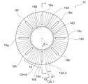
- FIG. 2 is a plan view of a separation plate according to the first embodiment.
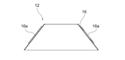
- FIG. 2 is a cross-sectional view of a separation plate according to the first embodiment.
- FIG. 11 is a schematic perspective view of a separation plate according to a second embodiment.
- FIG. 11 is a schematic perspective view of a separation plate according to a third embodiment.
- FIG. 11 is a plan view of a separation plate according to a third embodiment.
- the centrifugal separation device 100 is assumed to be a centrifugal separation device used for purification of raw liquid, which is a fluid to be treated, such as fuel oil and lubricating oil for marine diesel engines, and for classification, separation operations, and the like in various industrial fields.
- This centrifuge 100 is a vertical separation plate type centrifuge in which a number of separation plates made of thin truncated cone-shaped plates are stacked with small gaps between them along the axial direction of a guide tube inside a rotor, and components with different specific gravities are separated inside the rotor by centrifugal force.
- the components with different specific gravities are impurities with different specific gravities contained in the fluid to be treated, and more specifically, are solids and water content that are separated and deposited within the rotor by centrifugal force.
- the detector 200 detects frame vibrations of the centrifuge device 100, and when it determines that the frame vibrations are abnormal (abnormal operation of the centrifuge device), it performs a predetermined notification process via the first notification unit. This stops the operation (operation) of the centrifuge device where the abnormal vibrations are occurring.
- the detector 200 has a housing 202 that is rectangular when viewed from the front, and the housing 202 is disposed on the outer peripheral surface 100a of the centrifuge device 100.
- the shape of the housing 202 is not particularly limited, and can be appropriately modified within the scope of the present invention.
- the housing 202 is open at the front and is composed of a hollow main body 204 that is tightly attached to the outer peripheral surface 100a of the centrifuge device 100 by screwing or the like, and a lid 206 that is removably arranged on the front of the main body 204 (see Figure 3).
- the main body 204 includes a determination unit 212, a vibration detection sensor 216, and a first notification unit 218.
- the determination unit 212 is disposed in the open front area of the main body 204, and is connected to a vibration detection sensor 216 to measure frame vibration of the centrifuge device 100 and determine whether or not there is abnormal vibration of the device.
- the internal memory of the determination unit 212 has a digital filter, and a detection frequency and a detection frequency range are set.
- the judgment unit 212 is also connected to an inlet pressure detection sensor 222, a temperature detection sensor 224, an outlet pressure detection sensor 226, a circulation line pressure detection sensor 228, and a rotation speed detection sensor 230, and judges whether or not there is an abnormality in each of them.
- the front side of the determination unit 212 is provided with a display unit 214 constituting the first notification unit 218.
- the bottom plate 204c of the main body 204 is provided with wiring introduction sections 208 that are connected to the inlet pressure detection sensor 222, temperature detection sensor 224, outlet pressure detection sensor 226, circulation line pressure detection sensor 228, and rotation speed detection sensor 230, respectively, and wiring extraction sections 210 that send abnormal outflow detection signals, discharge failure detection signals, temperature abnormality detection signals, moisture abnormality detection signals, abnormal vibration detection signals, outlet pressure high pressure detection signals, etc. from the determination unit 212 to the control unit.
- the control unit is disposed outside the detector 200, it is also possible to dispose it inside the detector 200.
- a window 206a is formed in the cover 206, and the display unit 214 is visible through the window 206a (see Figure 2).
- the vibration detection sensor 216 is assumed to be an acceleration sensor.
- the acceleration sensor 216 is disposed so as to be in intimate contact with the inner surface of the rear plate 204a of the main body 204 in the housing 202 that is in intimate contact with the outer circumferential surface 100a of the centrifugal separator 100, as shown in the schematic diagram of FIG.
- the acceleration sensor 216 is connected to the determination unit 212 and measures the frame vibration of the centrifugal separator 100 .
- the acceleration sensor 216 is disposed inside the housing 202 of the detector 200 in order to make it compact, but it may also be disposed on the outer circumferential surface of the housing 202. Also, it may be disposed in close contact with the outer circumferential surface 100a of the centrifugal separator 100 in order to avoid the effects of resonance with the housing 202.
- the first notification unit 218 includes a lamp unit 219 arranged to protrude outward from the top plate 204 b of the main body 204 of the housing 202 , and the display unit 214 .
- three lamp units 219 are arranged in a row.
- Each lamp unit 219 is connected to the determination unit 212, and performs a reporting operation by lighting up, blinking, etc. in response to a signal from the determination unit 212.
- the lamp units 219 are, from the left, a yellow LED lamp 219a, a green LED lamp 219b, and a red LED lamp 219c when viewed from the front of the detector 200 shown in Fig. 2.
- the yellow LED lamp 219a is set to flash when the outlet pressure is close to the set pressure (within ⁇ 15%) and to light up when it is within the set range (within ⁇ 3%).
- the green LED lamp 219b is set to light up when the centrifugal separator 100 is rotating normally (operating normally).
- the red LED lamp 219c is set to light up (or flash) during abnormal rotation (operating abnormally). This makes it possible to visually notify whether the centrifugal separator 100 is operating normally or abnormally. It is also possible to use a red rotating warning light, so-called a patrol lamp, instead of the red LED lamp 219c.
- the first notification unit 218 is assumed to provide an auditory notification (alarm sound) in addition to a visual notification by the lamp unit 219.
- the display unit 214 has an LED display function, and is connected to the determination unit 212 which receives signals from various sensors.
- the display area indicated by reference numeral 214a displays the amount of passing liquid
- the display area indicated by reference numeral 214b displays the temperature of the passing liquid
- the area indicated by reference numeral 214c displays the light liquid outlet pressure, the horizontal axis rotation speed, the heavy liquid circulation pressure, the vibration speed, etc. as appropriate.
- the LED display is not particularly limited to this embodiment, and can be modified in design according to specifications.
- Data on frame vibration detected by the acceleration sensor 216 is digitally filtered in accordance with the detection frequency and detection frequency range set in the internal memory of the determination unit 212 .
- the vibration component of the centrifugal separator 100 is 180 Hz
- the detection frequency is 180 Hz
- the detection frequency range is ⁇ 10 Hz
- the acceleration of only the vibration component in the 180 Hz ⁇ 10 Hz band is converted into velocity.
- the digital filters use low-pass filters, high-pass filters, and band-pass filters to attenuate frequency components outside the detection frequency range, thereby detecting only specific frequency components (see FIGS. 5 to 7).
- the detection frequency range is preferably in the range of 1 to 30 Hz.
- the acceleration after digital filtering is integrated and converted to vibration velocity.
- the average value of a certain amount of measurement values (400 points) is subtracted to remove offset, and then root mean square processing is performed to calculate the effective value (peak value x 1/ ⁇ 2).
- the 1 second average of the effective velocity value is calculated. (Updated every 0.5 seconds)
- the calculated one second average value is compared with speed setting value 1 and speed setting value 2, and if the state where the speed is greater than or equal to the speed holding time and the speed setting continues, an abnormal vibration alarm is output.
- the speed setting value and the speed holding time are set in the internal memory of the determination unit 212 . There are two types of speed setting values, and the speed holding time for each is the same.
- the vibration speed can be selected from four options: X-axis/Y-axis/Z-axis/3-axis composite, using the internal memory settings.
- the acceleration sensor 216 is disposed inside the housing 202 of the detector 200, and the calculation processing is also performed by the determination unit 212 disposed inside the detector 200. Therefore, there is no need to attach a new vibration measuring device to the outer circumferential surface 100a of the centrifuge device 100, and no additional processing of the frame is required. According to the present embodiment, it is possible to accurately detect only the vibration component of the centrifuge device 100 without being affected by vibrations in the surrounding environment, and it is possible to constantly monitor the vibration state. Therefore, it is possible to accurately detect the occurrence of abnormal vibrations in the centrifuge device 100 and appropriately control the operating state.
- a second notification unit 220 is provided to enable remote detection of an abnormal operating state of the centrifuge device 100 from a remote location.
- the second notification unit 220 not only the first notification unit 218 of the detector 200 and the monitor display of the display unit 214 are possible, but also remote monitoring by an operator in a remote location such as an engine control room is possible, and when the vibration becomes large or an alarm is output, it is possible to check even in a different location.
- Items output to the second notification unit 220 can include, for example, the amount of passing liquid, the passing liquid temperature, the light liquid outlet pressure, the horizontal axis rotation speed, the heavy liquid circulation pressure, or the vibration speed, similar to the display displayed by the LED on the display unit 214.
- the second notification unit is assumed to have an analog output, but a digital output is also within the scope of the present invention.
- the detector 200 of this embodiment detects abnormal vibrations using the vibration detection sensor 216, and also has the following detection functions, for example. That is, a single detector can monitor information necessary for the operation of the centrifuge device 100, such as flow rate, temperature, pressure, rotation speed, and vibration. Also, by detecting abnormalities in the centrifuge device 100 and outputting an alarm, trouble can be prevented before it occurs.
- the notification process to the first notification unit 218 will be explained, but along with the notification signal to the first notification unit 218, a notification signal is also sent to the second notification unit 220, and an abnormal condition is remotely notified at a remote location.
- the determination unit 212 determines whether the discharge side pressure of the liquid to be treated exceeds the rated outlet pressure using an outlet pressure detection sensor 226 provided on the discharge side, and if it does exceed the rated outlet pressure, the determination unit 212 outputs an outlet pressure high pressure detection alarm signal and turns on the "Alarm" LED on the display unit 214 of the detector 200 and the "LP Hi” LED (not shown) on the board of the determination unit 212. Also, the outlet pressure value is displayed in the LED display area 214c of the display unit 214. Note that if the outlet pressure falls below the rated outlet pressure, the alarm signal is turned OFF. Also, a control may be provided that automatically adjusts the back pressure regulating valve based on the output alarm signal. According to this embodiment, since it is equipped with a function for detecting high outlet pressure, it is possible to minimize the loss of treated liquid due to operational errors, and even when the system is operated in an unmanned environment, problems can be dealt with using only the detector function.
- Leak detection function The system detects abnormal leakage from the centrifuge device 100 (oil leakage into the heavy liquid outlet side) or leakage of the processing liquid due to improper closing of the valve from a drop in pressure, outputs an alarm, and stops operation of the centrifuge device after the sludge is discharged, thereby minimizing loss of processing liquid.
- Partial emission detection function During partial discharge, in which only a portion of the rotor's capacity is discharged, the amount of sludge discharged is indirectly detected from the decrease in the rotation speed of the centrifugal separator, and an internal LED indicates whether the amount of discharge is appropriate. That is, the rotation speed detection sensor 230 detects and monitors a decrease in rotation speed, and the sludge discharge amount is indirectly measured from the amount of change in rotation speed while the discharge signal is being input. The amount of sludge discharged is then divided into three conditions: within the appropriate range, above the appropriate amount, and below the appropriate amount, and an LED on the board of the judgment unit 212 is turned on.
- Moisture detection function This function notifies the user that a certain amount of moisture has accumulated in the rotor before it is recirculated back into the light liquid (clean liquid) after being separated from the raw liquid during operation.
- the circulation line pressure detection sensor 228 detects the moisture and monitors the circulation pressure on the heavy liquid side.
- the determination unit 212 receives a detection signal from the circulation line pressure detection sensor 228 and sends a notification that a certain amount of moisture has accumulated in the rotor to the first notification unit 218, and displays the circulation line pressure value in the display area 214c of the display unit 214.
- the centrifuge 100 applied to this embodiment is a separation plate type centrifuge having a guide tube 101 that guides the raw liquid 13, which is the fluid to be treated and is supplied from above into a rotating vessel 11 that is attached to a rotating shaft (not shown) and rotates at high speed, in a diverging manner toward the bottom of the rotating vessel, and a number of separation plates 12 that are mounted in a stack with small gaps in the axial direction of the guide tube 101 to separate each component in the raw liquid 13, such as component 13B having a different specific gravity, from a separated liquid 13A based on the difference in specific gravity.
- the components with a high specific gravity solids, water, etc.
- the components with a low specific gravity are separated into the center side of the rotating vessel 11, and the separated liquid 13A is discharged from the top of the rotating vessel.
- the separation plate 12 (disk) is made of stainless steel and has a thickness of, for example, 0.3 mm to 1.0 mm, preferably 0.3 to 0.6 mm, and has a cap shape, i.e., a truncated cone shape with a conical surface 14 in which the upper end is cut off along a plane parallel to the open bottom surface and a ring-shaped portion 14A is provided on the inner periphery within the same plane.
- a rectangular gap piece (hereinafter also referred to as a "gap piece") 16 is provided in the direction along the conical generatrix of the separation plate 12, which constitutes a gap portion for maintaining the interval D between the stacked separation plates 12 at, for example, 0.3 mm to 1.0 mm, preferably 0.3 to 0.6 mm when assembled into a separation plate type centrifuge device.
- a notch 14B is formed on part of the inner circumference of the ring-shaped portion 14A, and a key is inserted between the notch 14B and the key groove 101a formed in the guide tube 101 shown in Figure 8, allowing the separation plate 12 to be positioned in the rotational direction (synchronized and prevented from rotating).
- the separation capacity (throughput) when the fluid to be treated is treated between the separation plates 12 by centrifugation is generally proportional to the settling area, i.e., the surface area of the separation plates 12. Therefore, in order to increase the separation capacity, the number of separation plates 12 or the outer diameter is usually increased.
- an uneven pattern 15 consisting of uneven portions on the front and back surfaces is formed on the front and back surfaces of the separation plate 12 in the area between the rectangular gap pieces 16 provided on the conical surface 14.
- the separation plate of this embodiment is a truncated cone shape that is stacked inside the rotating container 11 at a predetermined interval in the stacking direction and separates components with different specific gravities contained in the raw liquid 13, which is the fluid to be treated and introduced into the rotating container 11, by centrifugal force.
- the separation plate 12 is formed with a convex portion 12A and a concave portion 12B, and is formed in a linear shape along the generating line of the conical surface 14 of the separation plate 12, forming an uneven pattern 15 from the lower edge 14C of the conical surface 14 toward the upper edge 14D of the conical surface 14.
- the first separation plate 12-1 has eight rectangular gap pieces 16 (16a to 16h) that are provided on the surface side of the conical surface 14 of the first separation plate 12-1, run along the generatrix of the conical surface 14, and maintain a predetermined distance D between them and the other second separation plates 12-2 that are stacked in sequence.
- the gap pieces 16 are attached by welding.
- a concave-convex pattern 15 is formed between a first gap piece 16a and a second gap piece 16b that are provided adjacent to each other in the circumferential direction of the separation plate 12.
- the concave-convex pattern 15 is made up of eight patterns (first to eighth patterns) as shown in Fig. 11, and is made up of a plurality of convex portions 12A and a plurality of concave portions 12B of the first pattern 15.
- the angle ⁇ 1 between the first convex portion 12A-1 and the second convex portion 12A-2 adjacent to this first convex portion 12A-1 is formed to be 10 degrees or less, more preferably 8 degrees or less. This is because, if the angle exceeds 10 degrees, the flow straightening effect is not fully exhibited in the flow straightening area 17 formed by the distance D between the separation liquid and the separation plate, as described below.
- a plurality of gap pieces 16 are provided at predetermined intervals in the circumferential direction on the surface of the separation plate 12 .
- the number of the spacer pieces 16 is preferably 6 to 12, and more preferably 6 to 10.
- gap pieces 16a to 16h are provided along the conical surface 14, and the angle ⁇ between gap pieces 16a and 16b is 45 degrees.
- an uneven pattern 15 consisting of six convex portions 12A and five concave portions 12B is formed between the first gap piece 16a and the second gap plate 16b adjacent to the first gap piece 16a.
- the angle ⁇ 1 between the first convex portion 12A-1 forming the concave-convex pattern 15 and the second convex portion 12A-2 adjacent to the first convex portion 12A-1 is 5 degrees.
- the angle ⁇ 2 between the first gap piece 16a and the first convex portion 12A-1 adjacent thereto is 10 degrees, forming a flat surface 14E.
- both side areas of the first gap piece 16a are flat surfaces 14E, ensuring that the uneven pattern 15 is formed with a predetermined spacing when the separation plate 12 is molded, for example.
- the angle will change depending on the number of gap pieces 16 installed, but for example, if there are eight gap pieces 16, ⁇ is 45 degrees, in which case ⁇ 1 can be set to approximately 3 to 8 degrees. In this case, if ⁇ 1 is 3 degrees, ⁇ 2 should preferably be 15 degrees, and if ⁇ 1 is 8 degrees, approximately 3 degrees.
- the stacked area between the gap piece 16-1 at the bottom of the stack and the gap piece 16-2 at the top of the stack forms a straightening area 17 between the front surface of the separation plate 12-1 at the bottom of the stack in the stacked area and the back surface of the other separation plate 12-2 at the top of the stack.
- the flow of the introduced raw liquid 13 is straightened by the formation of the straightening region 17, and the raw liquid 13 flows upward through the gap D between the multiple stacked separation plates.
- the components with a high specific gravity (i.e., solids and moisture) 13B that have settled on the back surface of the upper separation plate 12-2 of the stack are not stirred up by the turbulent flow, and as a result, the components with a high specific gravity are separated toward the outer diameter part of the rotor, while the separated liquid 13 is separated toward the center of the rotating vessel 11, improving the separation ability.
- a high specific gravity i.e., solids and moisture
- laminar flow is a flow in one direction as shown in the flow diagram in the area of uneven pattern 15A (where the angle ⁇ 1 between first convex portion 12A-1 and second convex portion 12A-2 adjacent to first convex portion 12A-1 is 10 degrees or less) that has six convex portions on the conical surface 14 of the separation plate, as shown in the schematic image diagram of Figure 9.
- the flow diagram in the area of uneven pattern 15B where ⁇ 1 exceeds 10 degrees the flow is not laminar but turbulent, where the streamlines intersect, and the two flows are different.
- FIGS. 17(a) and 17(b) schematic flow diagrams of streamline images of partial cross sections of the separation plate shown at Xa and Xb in FIG. 16 are shown in FIGS. 17(a) and 17(b).
- the flow velocity F1 near the wall of the separator plate is smaller than the flow velocity F11 on the wall side of the turbulent flow shown in the image of flow lines in Fig. 17(b).
- components with different specific gravities (solids, water, etc.) in the introduced stock solution 13 tend to move toward the outer diameter side.
- the separation plate 12 rotates at high speed counterclockwise during centrifugation, causing the separated liquid to slide on the separation plate 12 in the direction of the delayed rotation, and not receiving sufficient centrifugal force, resulting in reduced separation efficiency.
- the surface area of the conical surface 14 is larger, so it is easy to increase the processing capacity. Therefore, it is easy to obtain high processing capacity, for example, when the particle size is very small.
- the gap pieces 16 are arranged in the form of flat plates in the generatrix direction with a specified interval between them, so even when multiple plates are stacked, the separation plates on the stacked side are prevented from shifting from each other due to compression or centrifugal force, eliminating factors such as deformation of the separation plates and mechanical vibration.
- the concentrate is introduced more reliably into the gaps than if it were not formed from the lower edge 14C, and laminar flow can be formed immediately.
- the circumferential region is provided with a discharge mechanism that discharges components with different specific gravities separated by centrifugal force to the outside.
- This mechanism is a self-discharge mechanism that discharges components with different specific gravities (solids, moisture, etc.) that have accumulated instantaneously while maintaining the rotation of the separation plate 12 of the centrifuge device.
- the valve cylinder 111 which moves up and down moves to the upper side and the outer circumferential upper edge 111a is pressed against the seal portion 112 to close the intermittent discharge port 113 and deposit components with different specific gravities (solids, etc.). Then, when the amount of deposits in the rotating vessel 11 reaches a predetermined amount, for example, based on the amount of the processed raw liquid 13 and the content of the components with different specific gravities, the valve cylinder 111 is moved downward to discharge the raw liquid from the intermittent discharge port 113 in one go.
- a predetermined amount for example, based on the amount of the processed raw liquid 13 and the content of the components with different specific gravities
- FIG. 13 is a schematic perspective view of a separation plate according to the second embodiment.
- the separation plate of this embodiment has a plurality of notched liquid passage holes 19 formed in the lower edge portion 14C of the conical surface 14.
- the raw liquid 13 can be reliably distributed and supplied to each separation plate when a plurality of plates are stacked.
- FIGS. 14 and 15 are schematic perspective and plan views of a separation plate according to a third embodiment.
- the predetermined concave-convex pattern 15 is not formed over the entire circumference. This is because if the concave-convex pattern 15 is formed up to the upper edge 14D, there is a high possibility that cracks or deformation will occur during manufacturing. For this reason, by not forming the predetermined concave-convex pattern 15 in the circumferential region 14a, it is possible to improve processability and improve the manufacturing yield.
- the present invention can be used in centrifuges in general and other equipment in general.
Landscapes
- Centrifugal Separators (AREA)
Priority Applications (3)
| Application Number | Priority Date | Filing Date | Title |
|---|---|---|---|
| KR1020267001771A KR20260023589A (ko) | 2023-07-20 | 2024-06-06 | 검출기 |
| JP2025533900A JP7833618B2 (ja) | 2023-07-20 | 2024-06-06 | 検知器 |
| CN202480047995.9A CN121532255A (zh) | 2023-07-20 | 2024-06-06 | 感测器 |
Applications Claiming Priority (2)
| Application Number | Priority Date | Filing Date | Title |
|---|---|---|---|
| JP2023-118002 | 2023-07-20 | ||
| JP2023118002 | 2023-07-20 |
Publications (1)
| Publication Number | Publication Date |
|---|---|
| WO2025018047A1 true WO2025018047A1 (ja) | 2025-01-23 |
Family
ID=94281815
Family Applications (1)
| Application Number | Title | Priority Date | Filing Date |
|---|---|---|---|
| PCT/JP2024/020639 Pending WO2025018047A1 (ja) | 2023-07-20 | 2024-06-06 | 検知器 |
Country Status (4)
| Country | Link |
|---|---|
| JP (1) | JP7833618B2 (https=) |
| KR (1) | KR20260023589A (https=) |
| CN (1) | CN121532255A (https=) |
| WO (1) | WO2025018047A1 (https=) |
Cited By (1)
| Publication number | Priority date | Publication date | Assignee | Title |
|---|---|---|---|---|
| CN120532653A (zh) * | 2025-07-29 | 2025-08-26 | 山西辰晖选矿设备股份有限公司 | 一种离心机状态在线监测方法及系统 |
Citations (4)
| Publication number | Priority date | Publication date | Assignee | Title |
|---|---|---|---|---|
| JPS53109864U (https=) * | 1977-02-10 | 1978-09-02 | ||
| JPS58189057A (ja) * | 1982-04-30 | 1983-11-04 | Tsubakimoto Chain Co | 遠心分離機の監視装置 |
| JP2000321121A (ja) * | 1999-05-12 | 2000-11-24 | Mitsubishi Kakoki Kaisha Ltd | 振動検知装置 |
| JP2017119261A (ja) * | 2015-12-30 | 2017-07-06 | 日立工機株式会社 | 遠心機及び遠心機の運転管理方法 |
Family Cites Families (3)
| Publication number | Priority date | Publication date | Assignee | Title |
|---|---|---|---|---|
| JPH06343900A (ja) * | 1993-06-02 | 1994-12-20 | Mitsubishi Kakoki Kaisha Ltd | 遠心濾過機の振動制御装置及び方法 |
| JP6867220B2 (ja) * | 2017-04-25 | 2021-04-28 | 株式会社村田製作所 | センサユニット |
| WO2024122632A1 (ja) * | 2022-12-08 | 2024-06-13 | 三菱化工機株式会社 | 遠心分離装置および分離板 |
-
2024
- 2024-06-06 CN CN202480047995.9A patent/CN121532255A/zh active Pending
- 2024-06-06 KR KR1020267001771A patent/KR20260023589A/ko active Pending
- 2024-06-06 JP JP2025533900A patent/JP7833618B2/ja active Active
- 2024-06-06 WO PCT/JP2024/020639 patent/WO2025018047A1/ja active Pending
Patent Citations (4)
| Publication number | Priority date | Publication date | Assignee | Title |
|---|---|---|---|---|
| JPS53109864U (https=) * | 1977-02-10 | 1978-09-02 | ||
| JPS58189057A (ja) * | 1982-04-30 | 1983-11-04 | Tsubakimoto Chain Co | 遠心分離機の監視装置 |
| JP2000321121A (ja) * | 1999-05-12 | 2000-11-24 | Mitsubishi Kakoki Kaisha Ltd | 振動検知装置 |
| JP2017119261A (ja) * | 2015-12-30 | 2017-07-06 | 日立工機株式会社 | 遠心機及び遠心機の運転管理方法 |
Cited By (1)
| Publication number | Priority date | Publication date | Assignee | Title |
|---|---|---|---|---|
| CN120532653A (zh) * | 2025-07-29 | 2025-08-26 | 山西辰晖选矿设备股份有限公司 | 一种离心机状态在线监测方法及系统 |
Also Published As
| Publication number | Publication date |
|---|---|
| CN121532255A (zh) | 2026-02-13 |
| JP7833618B2 (ja) | 2026-03-19 |
| JPWO2025018047A1 (https=) | 2025-01-23 |
| KR20260023589A (ko) | 2026-02-20 |
Similar Documents
| Publication | Publication Date | Title |
|---|---|---|
| WO2025018047A1 (ja) | 検知器 | |
| EP1984119B1 (en) | Method for supervising a centrifugal separator | |
| US10258905B2 (en) | Monitoring and controlling hydrocyclones using vibration data | |
| JPS6352947B2 (https=) | ||
| KR102110370B1 (ko) | 가스 정화를 위한 분리기 장치 | |
| EP2871479B1 (en) | Anti-clog and non-metallic debris detector for lubrication system inlet | |
| JP6437220B2 (ja) | 油分離装置及びこの油分離装置を用いたスクリュー圧縮機 | |
| JPH0365259A (ja) | くず粒子を流体から分離するサイクロン装置 | |
| JPH04318230A (ja) | 潤滑剤濾過システム及びガスタービンエンジンへの濾過潤滑剤流の供給方法 | |
| US4795561A (en) | Self regulating cyclonic separator | |
| KR20050026408A (ko) | 크랭크실 가스의 정화를 위한 방법 및 장치 | |
| KR20200053478A (ko) | 쿨런트액처리시스템 | |
| KR102371348B1 (ko) | 윤활 기계 시스템을 모니터링하기 위한 방법 및 시스템 | |
| CN111957159A (zh) | 一种卧式组合过滤分离器 | |
| EP0743096B1 (en) | Reduced size apparatus for centrifugal separation | |
| US5024755A (en) | Cone wear detection | |
| EP3261745B1 (en) | Oil separator for refrigeration and/or air conditioning plants | |
| CN201423315Y (zh) | 碟式分离机轴承润滑系统的改进结构 | |
| US3797663A (en) | Method of separating particles contained in a laden fluid, and a dynamic separator for performing this method | |
| CN219647068U (zh) | 分离装置 | |
| CN112474082A (zh) | 一种用于离心机超速的安全检测及限制的方法 | |
| KR200401764Y1 (ko) | 복합식 원심분리 필터 | |
| EP0110410B1 (en) | Debris detection system and method | |
| JPH0215823B2 (https=) | ||
| CN114183218A (zh) | 一种发动机曲轴箱通风系统及其使用方法 |
Legal Events
| Date | Code | Title | Description |
|---|---|---|---|
| WWE | Wipo information: entry into national phase |
Ref document number: 2025533900 Country of ref document: JP |
|
| 121 | Ep: the epo has been informed by wipo that ep was designated in this application |
Ref document number: 24842843 Country of ref document: EP Kind code of ref document: A1 |
|
| ENP | Entry into the national phase |
Ref document number: 1020267001771 Country of ref document: KR Free format text: ST27 STATUS EVENT CODE: A-0-1-A10-A15-NAP-PA0105 (AS PROVIDED BY THE NATIONAL OFFICE) |
|
| WWE | Wipo information: entry into national phase |
Ref document number: 1020267001771 Country of ref document: KR |
|
| WWP | Wipo information: published in national office |
Ref document number: 1020267001771 Country of ref document: KR |
|
| NENP | Non-entry into the national phase |
Ref country code: DE |