WO2025017876A1 - 香味吸引物品用のロッド部、非燃焼型香味吸引物品、非燃焼型香味吸引システム - Google Patents
香味吸引物品用のロッド部、非燃焼型香味吸引物品、非燃焼型香味吸引システム Download PDFInfo
- Publication number
- WO2025017876A1 WO2025017876A1 PCT/JP2023/026437 JP2023026437W WO2025017876A1 WO 2025017876 A1 WO2025017876 A1 WO 2025017876A1 JP 2023026437 W JP2023026437 W JP 2023026437W WO 2025017876 A1 WO2025017876 A1 WO 2025017876A1
- Authority
- WO
- WIPO (PCT)
- Prior art keywords
- region
- water
- wrapper
- rod
- based adhesive
- Prior art date
- Legal status (The legal status is an assumption and is not a legal conclusion. Google has not performed a legal analysis and makes no representation as to the accuracy of the status listed.)
- Pending
Links
Images









Classifications
-
- A—HUMAN NECESSITIES
- A24—TOBACCO; CIGARS; CIGARETTES; SIMULATED SMOKING DEVICES; SMOKERS' REQUISITES
- A24C—MACHINES FOR MAKING CIGARS OR CIGARETTES
- A24C5/00—Making cigarettes; Making tipping materials for, or attaching filters or mouthpieces to, cigars or cigarettes
- A24C5/14—Machines of the continuous-rod type
- A24C5/24—Pasting the seam
-
- A—HUMAN NECESSITIES
- A24—TOBACCO; CIGARS; CIGARETTES; SIMULATED SMOKING DEVICES; SMOKERS' REQUISITES
- A24D—CIGARS; CIGARETTES; TOBACCO SMOKE FILTERS; MOUTHPIECES OF CIGARS OR CIGARETTES; MANUFACTURE OF TOBACCO SMOKE FILTERS OR MOUTHPIECES
- A24D1/00—Cigars; Cigarettes
- A24D1/02—Cigars; Cigarettes with special covers
-
- A—HUMAN NECESSITIES
- A24—TOBACCO; CIGARS; CIGARETTES; SIMULATED SMOKING DEVICES; SMOKERS' REQUISITES
- A24D—CIGARS; CIGARETTES; TOBACCO SMOKE FILTERS; MOUTHPIECES OF CIGARS OR CIGARETTES; MANUFACTURE OF TOBACCO SMOKE FILTERS OR MOUTHPIECES
- A24D1/00—Cigars; Cigarettes
- A24D1/20—Cigarettes specially adapted for simulated smoking devices
Definitions
- the present invention relates to, for example, a rod portion for a flavor inhalation article, a non-combustion type flavor inhalation article, and a non-combustion type flavor inhalation system.
- WO 2017/104079 A1 discloses an embodiment of a seam portion at an overlapping portion of the wrappers of a filter segment.
- a hot melt adhesive which exhibits quick-drying and hardening properties when melted and cooled
- a water-based adhesive which has superior adhesive strength (peel strength) compared to hot melt adhesives
- the seam portion of a wrapper of a tobacco rod for a flavor inhalation product is fixed using both a hot melt adhesive and a water-based adhesive, and the seam portion is heated to a temperature above an appropriate temperature, such as between 200°C and 400°C, with a heater, the hot melt adhesive, which has a melting point of, for example, about 120°C to 200°C, may melt. In this case, the fixing strength of the seam portion of the heated wrapper may decrease.
- the present invention aims to provide a rod portion for a flavor inhalation article, a non-combustion type flavor inhalation article, and a non-combustion type flavor inhalation system that can suppress a decrease in strength of a seam portion of a wrapper of a tobacco rod or the like of a flavor inhalation article when the seam portion is heated.
- a rod portion for a flavor inhalation article has a filler, a wrapper formed in a sheet shape and covering the outer periphery of the filler, and a seam portion that fixes the overlapping portion of the wrapper.
- the seam portion has a first region made of a water-based adhesive that is provided along the axial direction of the rod portion at the overlapping portion between the ends of the wrapper, and a second region made of a water-based adhesive that is provided adjacent to the circumferential outside of the first region of the overlapping portion of the wrapper, and fixes the overlapping portion of the wrapper. Furthermore, no hot melt adhesive that melts when heated is used in the seam portion.
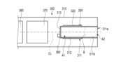
- FIG. 1 is a schematic diagram of a flavor inhalation system according to an embodiment.
- 2 is a diagram showing a schematic internal structure of the flavor inhalation device of the flavor inhalation system shown in FIG. 1 .
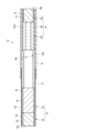
- FIG. 2 is a schematic vertical cross-sectional view of the flavor inhalation article shown in FIG. 1 .
- FIG. 3B is a schematic perspective view of a distal end rod of the rod portion shown in FIG. 3A .
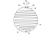
- 5 is a schematic diagram of the tip rod as viewed from the direction indicated by the arrow V in FIG. 4 .
- FIG. 5B is a schematic diagram of a modified distal rod shown in FIG. 5A.
- 5B is a schematic diagram showing a portion of the wrapper of the tip rod as viewed from the direction indicated by the arrow VI in FIG. 5A.
- 7 is a table showing the amount of water-based adhesive in the seam of the tip rods and the like shown in FIGS. 4 to 6 , the conveying speed during production, the peel strength, and the evaluation of the peel strength.
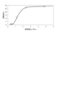
- 6 is a graph showing the relationship between the amount of water-based adhesive per unit length of a first seam portion and the like and peel strength.
- 3B is a schematic perspective view of a tobacco rod of the rod portion shown in FIG. 3A.
- 10 is a schematic diagram of the tobacco rod as viewed from the direction indicated by the arrow X in FIG. 9 .
- FIG. 11 is a schematic diagram showing a portion of a wrapper of a tobacco rod as viewed in the direction indicated by arrow XI in FIG. 10 .
- FIG. 3B is a schematic perspective view showing a state in which the rod portion and a part of the cooling portion shown in FIG. 3A are covered with an outer wrapper.
- 13 is a schematic diagram of a part of the cooling section and the outer wrapper as viewed from the direction indicated by the arrow XIII in FIG. 12 .
- 14 is a schematic view of a portion of the outer wrapper as viewed in the direction indicated by arrow XIV in FIG. 13 .
- FIG. 5B is a first modified schematic diagram showing a portion of the wrapper of the distal end rod as viewed in the direction indicated by the arrow VI in FIG. 5A.
- FIG. 5B is a second modified schematic diagram showing a portion of the wrapper of the distal end rod as viewed in the direction indicated by the arrow VI in FIG. 5A.
- FIG. 5B is a schematic diagram showing a third modification of a portion of the wrapper of the distal end rod as viewed in the direction indicated by the arrow VI in FIG. 5A.
- FIG. 5B is a schematic diagram showing a fourth modification of a portion of the wrapper of the distal end rod as viewed from the direction indicated by the arrow VI in FIG. 5A.
- FIG. 1 is a diagram showing the general structure of a non-combustion type flavor inhalation system 200 according to an embodiment.
- the flavor inhalation system 200 includes a non-combustion type flavor inhalation article (hereinafter, mainly referred to as the flavor inhalation article) 10 and a non-combustion type flavor inhalation device (hereinafter, mainly referred to as the device) 300 that heats the outer periphery of a tobacco rod (aerosol source) 24 (described later) of the flavor inhalation article 10.
- a non-combustion type flavor inhalation article hereinafter, mainly referred to as the flavor inhalation article
- the device 300 that heats the outer periphery of a tobacco rod (aerosol source) 24 (described later) of the flavor inhalation article 10.
- FIG. 2 is a diagram illustrating a schematic internal structure of the flavor inhalation device 300 according to the embodiment.
- the device 300 has a housing 310, which is a case for accommodating various components, a heater 320, a temperature sensor 350, a suction sensor 360, a control unit 370, and a power supply 380.
- the heater 320, the temperature sensor 350, the suction sensor 360, the control unit 370, and the power supply 380 are each provided in the housing 310.
- the housing 310 has a storage section 311 that stores the rod section 12 of the flavor suction article 10, which will be described later, in a removable manner from the open end (insertion opening) 311a to the closed end (bottom 313) on the rear side.
- the storage section 311 has a peripheral wall (cylindrical tube) 312 and a bottom 313.
- the storage section 311 forms an internal space as a cylindrical storage cavity 311b, into which the rod section 12 of the flavor suction article 10 can be inserted and removed by the peripheral wall 312 and the bottom 313 through the open end 311a.
- the outer diameter of the storage cavity 311b i.e., the inner diameter of the peripheral wall 312, may be equal to the outer diameter of the flavor suction article 10 or may be slightly larger. Therefore, the flavor suction article 10 is freely inserted and removed into the storage cavity 311b of the storage section 311 through the open end 311a of the device 300.
- the symbol CL indicates the central axis of the storage cavity 311b in the insertion/removal direction of the flavor inhalation article 10.
- the central axis of the flavor inhalation article 10 coincides with the central axis CL of the storage cavity 311b of the device 300.
- the direction along this central axis CL is also referred to as the axial direction of the rod portion 12, cooling portion (cooling segment) 14, and mouthpiece portion (mouthpiece segment) 16 of the device 300 and the flavor inhalation article 10.
- a heater 320 is provided around or within the peripheral wall 312 of the storage section 311.
- the peripheral wall 312 and bottom 313 of the storage section 311 are formed from a material that can withstand the heat of the heater 320 and transmit the heat of the heater 320 to the flavor inhalation article 10. Examples of materials that can be used for such a storage section 311 include metals such as stainless steel and heat-resistant resins.
- the heater 320 generates heat when power is supplied from the control unit 370, and heats the flavor inhalation article 10 contained in the container 311.
- the maximum heating temperature of the flavor inhalation article 10 by the heater 320 is, for example, between 200°C and 400°C. Examples of the maximum heating temperature vary depending on the heater 320 used.
- the space in the storage cavity 311b that is heated to a predetermined temperature by the heat of the heater 320 is the heated area A1, and the space adjacent to the opening end 311a of the heated area A1 in the axial direction (insertion/removal direction) is the non-heated area A2.
- the heated area A1 is formed on the bottom 313 side of the storage cavity 311b.
- the type of heater 320 is not particularly limited, but may be, for example, a steel material with a heating wire (e.g., a wire with high electrical resistance such as nichrome, iron chrome, or iron nickel) strung across it, or a ceramic heater, sheathed heater, or other heaters that are capable of controlling the temperature.
- a sheathed heater is a heater in which a heating wire is covered with a metal pipe together with a filler.
- the heater 320 is disposed around or inside the peripheral wall 312 in the heating area A1, and heats the heating area A1 from the outside.
- the heater 320 does not only heat the area in contact with the peripheral wall 312 of the storage section 311, but can also heat the peripheral wall 312 and bottom 313 of the storage section 311 that are distant from the heater 320 by radiation or heat transfer.
- the heater 320 heats the peripheral wall 312 from a position including the bottom 313 of the storage section 311 in the axial direction to a position B on the opening end 311a side, for example, to a predetermined temperature or higher.
- heated area A1 is the area between position B and bottom 313 in the axial direction of storage section 311.
- Position B is the boundary between heated area A1 and non-heated area A2, and non-heated area A2 is from boundary B to opening end 311a of storage cavity 311b in the axial direction.
- Boundary B may be set as the boundary between an area that reaches a predetermined temperature and an area that falls below the predetermined temperature when actually heated by heater 320, or it may be set as an estimated boundary between an area that reaches a predetermined temperature and an area that falls below the predetermined temperature when heater 320 is caused to generate heat under preset conditions.
- FIG. 1 shows the state in which the rod portion 12 of the flavor inhalation article 10 is inserted into the storage cavity 311b.
- the heater 320 receives power from the control unit 370, generates heat, and heats the outer periphery of the tobacco rod 24 to a predetermined temperature.
- the boundary position between the region where the peripheral wall 312 is at a predetermined temperature and the region where the temperature is below the predetermined temperature is estimated, and a plane that passes through this boundary position and is perpendicular to the central axis CL is defined as boundary B as shown by the two-dot chain line in Figure 2.
- the part of the storage cavity 311b where the tobacco rod 24 is located may be the heated area A1
- the part where the cooling section 14 is located may be the non-heated area A2.
- the flavor inhalation article 10 is inserted into the storage cavity 311b, and in this state, the heater 320 provided in the storage section 311 is made to generate heat, which heats the tobacco filling inside the flavor inhalation article 10, thereby generating an aerosol containing tobacco components, which the user can inhale.
- the control unit 370 controls the operating state of the device 300, such as controlling heating by the heater 320 based on the temperature sensor 350 and/or the suction sensor 360.
- the control unit 370 is a computer equipped with a processor such as a CPU (Central Processing Unit), a DSP (Digital Signal Processor), or an FPGA (Field-Programmable Gate Array), a memory such as a RAM (Random Access Memory) or a ROM (Read Only Memory), and an input/output unit.
- the flavor inhalation article 10 is used as a non-combustion type.
- the flavor inhalation article 10 according to this embodiment is formed in a substantially cylindrical rod shape.
- the flavor inhalation article 10 is
- the flavor inhalation article 10 has a substantially constant diameter over the entire length in the longitudinal direction (hereinafter also referred to as the axial direction) from the mouth end Me to the tip De.
- the entire length of the flavor inhalation article 10 is, for example, about 60 mm, and the outer diameter is, for example, 7 mm. That's about it.
- the flavor inhalation article 10 includes a rod portion (rod) 12, a cooling portion 14 provided downstream of the rod portion 12, a mouthpiece portion (filter portion) 16 provided downstream of the cooling portion 14, and a sheet-like tipping paper 18 that connects these together.
- the rod portion 12 is disposed in or near the portion heated by the device 300.
- the rod portion 12 has a tip rod (tip plug) 22 and a tobacco rod (tobacco segment, aerosol source) 24 adjacent to the downstream side of the tip rod 22. That is, the rod portion 12 has the tip rod 22 disposed on the opposite side of the mouthpiece portion 16 of the non-combustion type flavor inhalation article 10, and the tobacco rod 24 provided between the tip rod 22 and the cooling portion 14.
- the axial length and outer diameter of the tip rod 22 and the tobacco rod 24 can be changed as appropriate to suit the product of the non-combustion type flavor inhalation article 10.
- the axial length of the tip rod 22 is preferably about 5 mm, for example.
- the axial length of the tobacco rod 24 is preferably about 15 mm, for example.
- the entire circumference of the tobacco rod 24 is inside the heater 320, but a portion of the tip rod 22 may or may not be inside the heater 320.
- the tip rod 22 is formed as a so-called tip plug, for example, to act as a lid to prevent the filler 42 (described later) from falling out from the tip side of the tobacco rod 24.
- the tip rod 22 has a filler 32 and a sheet-like inner plug wrapper (segment wrapper) 34 that covers the outer periphery of the filler 32.
- the filler 32 of the tip rod 22 is preferably a paper sheet, a nonwoven sheet, a resin sheet, or cellulose acetate tow.
- the filler 32 of the tip rod 22 may include an aerosol-generating substrate.
- the type of the aerosol-generating substrate is not particularly limited, and various extracts from natural products and/or their components can be selected depending on the application.
- Examples of the aerosol-generating substrate include glycerin, propylene glycol, triacetin, 1,3-butanediol, and mixtures thereof.
- the filler 32 of the tip rod 22 is a sheet material made of paper, a sheet material made of nonwoven fabric, or a sheet material made of resin, which is creped (shrunk) and folded to form a roughly cylindrical rod of an appropriate length.
- a sheet material made of paper a material that a person skilled in the art can use as a paper filter can be used.
- the sheet material made of paper for example, glassine paper can also be used.
- the width of the base paper in the filler 32 is preferably, for example, 100 mm or more and 250 mm or less, more preferably 150 mm or more and 200 mm or less, for example 180 mm, and the basis weight is, for example, usually 20 gsm or more and usually 65 gsm or less.
- the basis weight of the base paper in the filler 32 is 35 gsm.
- the thickness of the filler 32 is not limited, and is usually 10 ⁇ m or more and usually 100 ⁇ m or less from the viewpoints of rigidity, breathability, and ease of adjustment during papermaking. In this embodiment, the thickness of the filler 32 is, for example, 88 ⁇ m.
- the air permeability of the paper sheet material is, for example, 0 CU (Colesta Unit) to 30,000 CU after creping.
- the air permeability of the sheet material of the filler 32 of the tip rod 22 is, for example, 3,000 CU.
- the air permeability is measured as follows. The sheet was left to stand for 48 hours under conditions of room temperature 22°C and relative humidity 60%. Next, this sheet was cut into a size of 40 mm x 240 mm, and measured using an air permeability measuring device (PPM1000M made by Cerulea) under measurement conditions of a differential pressure of 1 kPa and a circular measuring head of 2 cm2 . The measurement environment was set to room temperature 22°C and relative humidity 60%. The air permeability was calculated as the air flow rate ( cm3 ) per 1 cm2 per minute under a differential pressure of 1 kPa.
- the airflow resistance of the distal rod 22 is, for example, 0 mmH 2 O/mm to 12 mmH 2 O/mm, and preferably 4 mmH 2 O/mm to 8 mmH 2 O/mm.
- the crimp depth of the filler 32 is preferably in the range of 0.1 mm to 0.5 mm, and an example is 0.33 mm.
- Additives that can be added to the filler 32 include, for example, a plasticizer such as triacetin, an adsorbent such as activated carbon, and a flavoring agent such as menthol. It is preferable that these additives are dispersed approximately uniformly in the filler 32.
- the inner plug wrapper (hereinafter, mainly referred to as the wrapper) 34 is a sheet material for wrapping the outer periphery of the filler 32, and its configuration is not particularly limited, and a general one can be used.
- cellulose fiber paper can be used as the base paper used for the wrapper 34. More specifically, hemp, wood, or a mixture thereof can be used as the base paper used for the wrapper 34.
- the basis weight of the base paper in the wrapper 34 is, for example, usually 20 gsm or more, usually 100 gsm or less, and more preferably 30
- the base paper of the wrapper 34 according to the present embodiment has a basis weight of 43 gsm.
- the thickness of the wrapper 34 is not limited, and is usually 10 ⁇ m or more and usually 100 ⁇ m or less from the viewpoints of rigidity, breathability, and ease of adjustment during papermaking. In the present embodiment, the thickness of the wrapper 34 is, for example, 45 ⁇ m.
- the air permeability of the wrapper 34 is preferably 0.
- the shape of the wrapper 34 of the tip rod 22 can be, for example, a rectangular shape such as a square or a rectangle.
- the length of one side of the wrapper 34 can be about 5 mm, which defines the length along the axial direction of the tip rod 22.
- the length of the other side of the wrapper 34 defines the diameter of the tip rod 22.
- the length of the other side of the wrapper 34 is about 24 mm. In this embodiment, the length of the other side of the wrapper 34 is 23.7 mm.
- the wrapper 34 may contain a filler.
- the amount of the filler may be 10% by weight or more and less than 60% by weight based on the total weight of the wrapper 34.
- the filler is preferably 15% by weight or more and 45% by weight or less within the preferred basis weight range (25 gsm or more and 45 gsm or less).
- the filler calcium carbonate, titanium dioxide, kaolin, etc. can be used, but it is preferable to use calcium carbonate from the viewpoint of enhancing flavor and whiteness, etc.
- auxiliary agents other than the base paper and fillers may be added to the wrapper 34.
- a water resistance improver may be added to improve water resistance.
- Water resistance improvers include wet strength agents (WS agents) and sizing agents.
- wet strength agents include urea formaldehyde resin, melamine formaldehyde resin, polyamide epichlorohydrin (PAE), etc.
- sizing agents include rosin soap, alkyl ketene dimer (AKD), alkenyl succinic anhydride (ASA), highly saponified polyvinyl alcohol with a saponification degree of 90% or more, etc.
- a paper strength agent may be added as an auxiliary agent, such as polyacrylamide, cationic starch, oxidized starch, carboxymethyl cellulose (CMC), polyamide epichlorohydrin resin, polyvinyl alcohol, etc.
- auxiliary agent such as polyacrylamide, cationic starch, oxidized starch, carboxymethyl cellulose (CMC), polyamide epichlorohydrin resin, polyvinyl alcohol, etc.
- CMC carboxymethyl cellulose
- polyamide epichlorohydrin resin polyvinyl alcohol, etc.
- the wrapper 34 may also be appropriately coated.
- a coating agent may be added to at least one of the two surfaces of the wrapper 34, the front surface (outer surface) and the back surface (inner surface).
- the coating agent There are no particular limitations on the coating agent, but a coating agent that can form a film on the surface of the paper and reduce liquid permeability is preferred.
- alginic acid and its salts e.g., sodium salts
- polysaccharides such as pectin
- cellulose derivatives such as ethyl cellulose, methyl cellulose, carboxymethyl cellulose, and nitrocellulose
- starch and its derivatives e.g., ether derivatives such as carboxymethyl starch, hydroxyalkyl starch, and cationic starch
- ester derivatives such as starch acetate, starch phosphate, and starch octenyl succinate.
- the wrapper 34 has a first seam 36 formed by fixing the overlapping portions 34a to each other with water-based adhesives 37a and 37b, which will be described later.
- the fixing structure of the overlapping portion 34a of the wrapper 34 of the tip rod 22 described above will be described below.
- the circumferential width of the overlapping portion 34a of the wrapper 34 is 1 mm to 3 mm, and more preferably about 2.4 mm to 2.7 mm.
- Figure 4 is a schematic diagram showing the wrapper 34 wrapped around the outer circumference of the filler 32 of the tip rod 22.
- Figure 5A is a schematic diagram indicated by arrow V in Figure 4.
- Figure 6 is a schematic diagram showing the first seam portion 36 that secures the overlapping portion 34a of the wrapper 34 of the tip rod 22 as viewed from the direction indicated by arrow VI in Figure 5A.
- the wrapper 34 wraps around the outer periphery of the filler 32, which is formed, for example, from a sheet material processed into a generally cylindrical rod shape.
- the wrapper 34 is provided with a first seam portion 36 in which the ends of the generally rectangular sheet material are overlapped and bonded with water-based adhesives 37a, 37b to fix the overlapping portion 34a of the wrapper 34.
- the first seam portion 36 is provided along the axial direction of the rod portion 12 at the overlapping portion 34a of the ends of the wrapper 34.
- the first seam portion 36 does not use a hot melt adhesive that melts when heated to an appropriate temperature (e.g., a temperature suitable for generating an aerosol with the tobacco rod 24) as a fixing member for fixing the overlapping portion 34a.
- an appropriate temperature e.g., a temperature suitable for generating an aerosol with the tobacco rod 24
- the first seam portion 36 uses only a glue that prevents the fixing strength from decreasing to a desired fixing strength when heated to an appropriate temperature compared to before heating, or a glue or adhesive that prevents the fixing strength from decreasing to a desired fixing strength when heated to an appropriate temperature compared to before heating, i.e., a water-based adhesive, as a fixing member for fixing the overlapping portion 34a.
- the first seam portion 36 has a 1-1 region 36a to which a water-based adhesive 37a is applied, and a 1-2 region 36b that is adjacent to the circumferential outside of the 1-1 region 36a of the overlapping portion 34a of the wrapper 34 and to which a water-based adhesive 37b is applied.
- the 1-1 region 36a and the 1-2 region 36b are each approximately rectangular.
- the circumferential width of each of the 1-1 region 36a and the 1-2 region 36b is, for example, 0.1 mm to 1 mm, and preferably 0.2 mm to 0.5 mm.
- the water-based adhesives 37a and 37b are adhesives whose hardening is accelerated by evaporation of the water in the adhesive, and whose bonding strength is increased.
- the water-based adhesives 37a and 37b contain one of ethylene-vinyl acetate copolymer resin (EVA), polyvinyl alcohol (PVA), carboxymethyl cellulose (CMC), and starch paste, or a mixture of at least two of EVA, PVA, CMC, and starch paste.
- EVA ethylene-vinyl acetate copolymer resin
- PVA polyvinyl alcohol
- CMC carboxymethyl cellulose
- starch paste starch paste
- the water-based adhesives 37a and 37b are described as an example using ethylene-vinyl acetate copolymer resin (EVA).
- EVA ethylene-vinyl acetate copolymer resin
- the composition of the water-based adhesives 37a and 37b is 54% EVA and 46% water and the remainder.
- An example of the viscosity of the water-based adhesives 37a and 37b during the manufacture of the tip rod 22 is 1100 mPa ⁇ s. This is the same for the water-based adhesives 47a, 47b, 57a, and 57b described below.
- the water-based adhesives 37a and 37b are adhesives whose bonding strength increases as the water in the adhesive evaporates. For this reason, it is expected that the strength of the seam portion 36 will increase when heated to an appropriate temperature using the heater 320 of the device 300, and it is not expected that the strength of the seam portion 36 will decrease. In other words, the wrapper 34 suppresses the decrease in strength of the seam portion 36 when the seam portion 36 is heated.
- the 1-1 region 36a and the 1-2 region 36b are each provided along the axial direction of the rod portion 12.
- the 1-1 region 36a and the 1-2 region 36b are each continuous with water-based adhesives 37a, 37b along the axial direction of the rod portion 12.
- the water-based adhesive 37a is solidly applied in the 1-1 region 36a
- the water-based adhesive 37b is solidly applied in the 1-2 region 36b.
- a region (adhesive-free region) 38a free of water-based adhesive is provided along the axial direction of the rod portion 12.
- the circumferential width of the water-based adhesive-free region 38a between the 1-1 region 36a and the 1-2 region 36b, which intersects with the axial direction of the rod portion 12, is preferably 0.1 mm to 2 mm.
- an area (adhesive-free area) 38b that is free of water-based adhesive is formed between the 1-2 region 36b and the circumferentially outer end face 34b of the wrapper 34.
- the circumferential width of the area 38b that is free of water-based adhesive that intersects with the axial direction of the rod portion 12, i.e., the distance between the 1-2 region 36b of the wrapper 34 and the circumferentially outer end face 34b of the overlapping portion 34a is preferably greater than 0 mm and less than 2 mm. It is more preferable that this circumferential width be, for example, 0.1 mm to 1 mm.
- a region (adhesive-free region) 38c where there is no water-based adhesive is formed between the 1-1 region 36a and the end face 34c on the opposite side of the wrapper 34.
- the circumferential width of the region 38c where there is no water-based adhesive, which intersects with the axial direction of the rod portion 12, is preferably 0.1 mm to 1 mm.
- the region 38c does not have to be present, and the water-based adhesive 37a may be applied up to the end face 34c, or may be applied beyond the end face 34c to the filler 32. In other words, the filler 32 and the wrapper 34 may be joined by the water-based adhesive 37a.
- the total amount of water-based adhesive 37a in the 1-1 region 36a and the amount of water-based adhesive 37b in the 1-2 region 36b is, for example, 1 mg/120 mm to 5 mg/120 mm. It is preferable that the amount of water-based adhesive 37a in the 1-1 region 36a is greater than the amount of water-based adhesive 37b in the 1-2 region 36b, but they may be the same amount.
- the overlapping portion 34a of the wrapper 34 is fixed with the water-based adhesive 37a, 37b.
- the peel strength can be stably maintained.
- FIG. 7 shows a table indicating the amount of water-based adhesive 37a in the 1-1 region 36a, the amount of water-based adhesive 37b in the 1-2 region 36b, the total amount of water-based adhesive in the first seam portion 36, the feed speed during manufacture of the first seam portion 36 of the wrapper 34 of the tip rod 22, the peel strength of the first seam portion 36, and an evaluation of the peel strength of the first seam portion 36 for three samples.
- FIG. 7 also shows a table indicating the amount of water-based adhesive 37b in the 1-2 region 36b, the total amount of water-based adhesive, the feed speed during manufacture, the peel strength, and an evaluation of the peel strength for four samples in which the water-based adhesive 37a is not applied to the 1-1 region 36a.
- Figure 8 shows a correlation diagram of the peel strength (g) of the first seam portion 36 against the total amount of water-based adhesive (mg) per 120 mm 24 hours after manufacture.
- the horizontal axis represents the amount of water-based adhesive 37b (mg/120 mm) in the circumferentially outer 1-2 region 36b, and the vertical axis represents the peel strength (g).
- the peel strength of the first seam portion 36 was measured as follows using a measuring device EZ-SX (load cell 5N) manufactured by SHIMADZU at a pulling speed of 100 mm/min.
- the wrapper 34 here is sufficiently long and is not yet cut to a predetermined length (e.g., 5 mm).
- the wrapper 34 of the created tip rod 22 was cut in parallel to the axial direction of the rod portion 12 on the opposite side of the first seam portion 36 (the opposite side of the tip rod 22 to the first seam portion 36 across the central axis of the tip rod 22). In other words, the cut direction of the wrapper 34 is parallel to the axial direction of the 1-1 region 36a and the 1-2 region 36b.
- the tip of the first seam portion 36 of the cut-out wrapper 34 was peeled off by hand for about 3 mm to create a pair of gripping portions.
- the pair of gripping portions was created by peeling off the 1-1 region 36a and the 1-2 region 36b by about 3 mm from one end perpendicular to the circumferential outer end face 34b of the wrapper 34 and the circumferential inner end face 34c of the wrapper 34. Then, the pair of gripping portions was attached to the clamps of a peel tester, and a T-type peel test was performed.
- the overlapping portion 34a of the wrapper 34 bonded with the water-based adhesives 37a and 37b was peeled off at a predetermined speed along the longitudinal axis of the rod portion 12 to a displacement of 70 mm.
- the measurement results were expressed in g (grams) by calculating the median value of the load generated from the start of measurement (start of peeling) to a displacement of 70 mm, and the average value of five repetitions was expressed in g (grams).
- the total amount of water-based adhesive 37a, 37b per 120 mm is, for example, 1.1 mg or more.
- the amount of the water-based adhesive 37a in the 1-1 region 36a is greater than the amount of the water-based adhesive 37b in the 1-2 region 36b.
- the amount of the water-based adhesive 37b in the 1-2 region 36b on the outer side in the circumferential direction is made smaller than the amount of the water-based adhesive 37a in the 1-1 region 36a on the inner side in the circumferential direction, so that the water-based adhesive 37b in the 1-2 region 36b on the outer side in the circumferential direction dries faster than the water-based adhesive 37a in the 1-1 region 36a on the inner side in the circumferential direction.
- the overlapping portion 34a can first be fixed (temporarily fixed) in a desired state by the water-based adhesive 37b in the 1-2 region 36b on the outer side in the circumferential direction.
- the water-based adhesive 37a in the 1-1 region 36a dries less quickly than the water-based adhesive 37b in the 1-2 region 36b, the water-based adhesive 37a in the 1-1 region 36a exerts resistance to peeling of the first seam portion 36, and the first seam portion 36 is fixed in a state having a desired peel strength.
- the first seam portion 36 is fixed so as to have a peel strength of 10 g or more by the water-based adhesive 37b in the 1-2 region 36b, which exerts a fixing force earlier than the water-based adhesive 37a in the 1-1 region 36a, and the water-based adhesive 37a in the 1-1 region 36a, which ultimately exerts a fixing force greater than the water-based adhesive 37b in the 1-2 region 36b. It is also preferable that the amount of the water-based adhesive 37a in the 1-1 region 36a and the amount of the water-based adhesive 37b in the 1-2 region 36b are approximately equal.
- the quick-drying property of the seam portion 36 can be improved compared to the case where the seam portion 36 is formed in one region. Therefore, by using the seam portion 36 having the multiple regions 36a, 36b, the water-based adhesives 37a, 37b can be dried more quickly, and appropriate bonding strength can be obtained in the seam portion 36 more quickly.
- the peel strength of the first seam portion 36 increases as the total amount of the water-based adhesives 37a and 37b increases.
- the peel strength does not change significantly between the example where the total amount of the water-based adhesives 37a and 37b is 2.4 mg/120 mm and the example where the total amount of the water-based adhesives 37a and 37b is 4.8 mg/120 mm.
- the total amount of the water-based adhesives 37a and 37b of the first seam portion 36 should be, for example, about 2.4 mg/120 mm.
- the first seam portion 36 of the wrapper 34 of the tip rod 22 is manufactured while adjusting the amount of the water-based adhesives 37a and 37b so that it has an appropriate peel strength.
- the filler 32 is fixed to the wrapper 34 on the inner circumferential surface of the wrapper 34 by an adhesive 39 similar to the water-based adhesives 37a and 37b.
- the bonding position of the adhesive 39 can be set appropriately.
- the bonding position of the adhesive 39 is provided on the opposite side to the overlapping portion 34a.
- the tobacco rod 24 has a filler (tobacco filler) 42 as an aerosol generating base material and a sheet-like wrapper (wrapping paper) 44.
- the filler 42 is a tobacco sheet and/or cut tobacco.
- the material of the tobacco shreds contained in the filler 42 is not particularly limited, and known materials such as lamina and ribs can be used.
- the filler 42 may be a so-called strand type, in which a homogenized sheet having a length approximately equal to the length of the tobacco rod 24 is cut approximately horizontally to the length of the tobacco rod 24.
- the width of the tobacco shreds is preferably 0.5 mm or more and 2.0 mm or less when filling the tobacco rod 24.
- the content of the dried tobacco leaves contained in the filler 42 of the tobacco rod 24 is not particularly limited, but may be 200 mg/(tobacco rod) or more and 800 mg/(tobacco rod) or less.
- Various types of tobacco can be used for the tobacco leaves used to make the shredded tobacco and homogenized sheets. Examples include flue-cured tobacco, burley tobacco, oriental tobacco, native tobacco, other Nicotiana tabacum varieties, Nicotiana rustica varieties, and mixtures of these. Mixtures can be used by appropriately blending the above varieties to achieve the desired flavor.
- the moisture content of the tobacco filler 42 can be 10% by weight or more and 15% by weight or less based on the total amount of the tobacco filler 42. Such a moisture content suppresses the occurrence of stains on the wrapper 44 after wrapping the wrapper 44, and improves the suitability for rolling during the manufacture of the tobacco rod 24.
- dried tobacco leaves may be crushed to an average particle size of about 20 ⁇ m to 200 ⁇ m, homogenized, processed into a sheet, and then shredded to a width of 0.5 mm or more and 2.0 mm or less may be used.
- the tobacco filler 42 may contain an aerosol-generating substrate that generates an aerosol.
- the type of the aerosol-generating substrate is not particularly limited, and various extracts from natural products and/or their constituents can be selected depending on the application.
- Examples of the aerosol-generating substrate include glycerin, propylene glycol, triacetin, 1,3-butanediol, and mixtures thereof.
- the content of the aerosol-generating substrate in the tobacco filler 42 is not particularly limited, and is preferably usually 5% by weight or more and usually 50% by weight or less of the total amount of the tobacco filler 42 from the viewpoint of generating sufficient aerosol and imparting a good flavor.
- the tobacco filler 42 may contain a flavoring.
- the type of flavoring is not particularly limited, and from the viewpoint of imparting a good flavor, the following flavorings may be used: acetanisole, acetophenone, acetylpyrazine, 2-acetylthiazole, alfalfa extract, amyl alcohol, amyl butyrate, trans-anethole, star anise oil, apple juice, Peru balsam oil, beeswax absolute, benzaldehyde, benzoin resinoid, benzyl alcohol, benzyl benzoate, benzyl phenylacetate, benzyl propionate, 2,3-butanedione, 2-butanol, butyl butyrate, butyric acid, caramel, cardamom oil, carob absolute, ⁇ -Carotene, carrot juice, L-carvone, ⁇ -caryophyllene, cassia bark oil, cedarwood oil, celery
- the amount of flavoring contained in the tobacco filler 42 is not particularly limited, but from the viewpoint of imparting a good flavor, it is usually 10,000 ppm or more, and preferably 70,000 ppm or less.
- the wrapper (wrapping paper) 44 is a sheet material for wrapping the tobacco filler 42. There are no particular limitations on the composition of the wrapper 44, and a general one can be used.
- the base paper for the wrapper 44 of the tobacco rod 24 can be, for example, the same as the wrapper 34 of the tip rod 22.
- the length along the axial direction of the tobacco rod 24 is, for example, 15 mm.
- the length of one side of the wrapper 44 can be approximately 15 mm, which defines the length along the axial direction of the tobacco rod 24.
- the length of the other side of the wrapper 44 defines the diameter of the tobacco rod 24.
- the length of the other side of the wrapper 44 is approximately 24 mm. In this embodiment, the length of the other side of the wrapper 44 is 23.7 mm.
- a second seam 46 is formed in the wrapper 44, in which the overlapping portions 44a are fixed to each other by water-based adhesives 47a and 47b, which will be described later.
- the fixing structure of the wrapper 44 of the tobacco rod 24 will be described below with reference to Figures 9 to 11.
- the circumferential width of the overlapping portions 44a of the wrapper 44 is 1 mm to 3 mm, and more preferably about 2.4 mm to 2.7 mm.
- Figure 9 is a schematic diagram showing the state in which the wrapper 44 is wrapped around the outer circumference of the filler material 42 of the tobacco rod 24.
- Figure 10 is a schematic diagram indicated by arrow X in Figure 9.
- Figure 11 is a schematic diagram showing the second seam portion 46 that secures the overlapping portion 44a of the wrapper 44 of the tobacco rod 24, as viewed from the direction indicated by arrow XI in Figure 10.
- the wrapper 44 wraps around the outer circumference of the filler 42, which is formed into a generally cylindrical rod shape.
- the wrapper 44 is provided with a second seam portion 46 in which the ends of the generally rectangular sheet material are overlapped and bonded with water-based adhesives 47a and 47b to fix the overlapping portion 44a of the wrapper 44.
- a water-based adhesive is used in the second seam portion 46, and no hot melt adhesive that melts when heated is used.
- the second seam portion 46 is provided along the axial direction of the rod portion 12 in the overlapping portion 44a between the ends of the wrapper 44.
- the second seam portion 46 has a 2-1 region 46a to which a water-based adhesive 47a is applied, and a 2-2 region 46b to which a water-based adhesive 47b is applied, which is provided adjacent to the circumferential outside of the 2-1 region 46a of the overlapping portion 44a of the wrapper 44. Therefore, the seam portion 46 having multiple regions 46a, 46b allows the water-based adhesives 47a, 47b to dry more quickly, and the seam portion 46 can obtain an appropriate bonding strength more quickly.
- the 2-1 region 46a and the 2-2 region 46b are each approximately rectangular.
- the water-based adhesives 47a and 47b like the water-based adhesives 37a and 37b, contain one of ethylene-vinyl acetate copolymer resin (EVA), polyvinyl alcohol (PVA), carboxymethyl cellulose (CMC), and starch paste, or a mixture of at least two of EVA, PVA, CMC, and starch paste.
- EVA ethylene-vinyl acetate copolymer resin
- PVA polyvinyl alcohol
- CMC carboxymethyl cellulose
- starch paste starch paste
- the water-based adhesives 47a and 47b are adhesives whose bonding strength increases as the water in the adhesive evaporates. For this reason, it is expected that the strength of the seam portion 46 will increase by heating to an appropriate temperature using the heater 320 of the device 300, and no decrease in the strength of the seam portion 46 is expected. In other words, the wrapper 44 suppresses the decrease in strength of the seam portion 46 when the seam portion 46 is heated.
- the 2-1 region 46a and the 2-2 region 46b are each provided along the axial direction of the rod portion 12.
- the 2-1 region 46a and the 2-2 region 46b are each continuous with water-based adhesives 47a, 47b along the axial direction of the rod portion 12.
- a region (adhesive-free region) 48a that is free of water-based adhesive is provided along the axial direction of the rod portion 12.
- the circumferential width of the water-based adhesive-free region 48a between the 2-1 region 46a and the 2-2 region 46b that intersects with the axial direction of the rod portion 12 is preferably 0.1 mm to 2 mm.
- a region (adhesive-free region) 48b is formed in which there is no water-based adhesive.
- the circumferential width of the water-based adhesive-free region 48b, which intersects with the axial direction of the rod portion 12, is preferably 0.1 mm to 2 mm.
- a region (adhesive-free region) 48c is formed in which there is no water-based adhesive.
- the circumferential width of the region 48c in which there is no water-based adhesive, which intersects with the axial direction of the rod portion 12, is preferably 0.1 mm to 1 mm. Note that the region 48c does not have to be present, and the water-based adhesive 47a may be applied up to the end face 44c, or may be applied beyond the end face 44c to the filler 42. In other words, the filler 42 and the wrapper 44 may be joined by the water-based adhesive 47a.
- the total amount of water-based adhesive 47a in the 2-1 region 46a and the amount of water-based adhesive 47b in the 2-2 region 46b is, for example, 1 mg/120 mm to 5 mg/120 mm. It is preferable that the amount of water-based adhesive 47a in the 2-1 region 46a is greater than the amount of water-based adhesive 47b in the 2-2 region 46b, but they may be the same amount.
- the second seam portion 46 can maintain a fixed state at the overlapping portion 44a even when heated to an appropriate temperature at which, for example, aerosol is generated from the filler material 42 of the tobacco rod 24.
- the cooling section (paper tube) 14 is not particularly limited as long as it has the function of cooling the vapor generated by heating the tobacco rod 24, and an example of such a cooling section (paper tube) is cardboard (sheet material) processed into a cylindrical shape.
- a cooling section paper tube
- cardboard sheet material
- the inside of the cylinder is hollow, and the vapor containing the aerosol-generating base material and the tobacco flavor components is cooled by contacting the air inside the cavity.
- the cooling section 14 may be a paper tube formed by processing a single sheet of paper or a sheet of paper bonded together into a cylindrical shape.
- the cooling section 14 in order to increase the cooling effect by bringing the room temperature outside air into contact with the high-temperature steam, the cooling section 14 is provided with an opening 14a for taking in air from the outside.
- the number of openings 14a in the cooling section 14 is not particularly limited.
- a plurality of openings 14a are arranged at regular intervals in the circumferential direction of the cooling section 14.
- the group of openings 14a arranged in the circumferential direction of the cooling section 14 may be formed in a plurality of stages along the axial direction of the cooling section 14.
- the openings 14a in the cooling section 14 when the flavor inhalation article 10 is inhaled, low-temperature air flows into the cooling section 14 from the outside, and the temperature of the volatile components and air flowing in from the tobacco rod 24 can be reduced.
- the steam containing the aerosol-generating base material and the tobacco flavor components is condensed by being cooled by the low-temperature air introduced into the cooling section 14 through the openings 14a.
- the cooling effect can be increased by applying a polymer coating such as polyvinyl alcohol or a polysaccharide coating such as pectin to the inner surface of the paper tube, utilizing the heat absorption of the coating and the heat of dissolution associated with the phase change.
- a polymer coating such as polyvinyl alcohol or a polysaccharide coating such as pectin
- the airflow resistance of this cylindrical cooling segment is zero mmH2O .
- the total surface area of the cooling section 14 is not particularly limited, and may be, for example, 300 mm 2 /mm or more and 1000 mm 2 /mm or less. This surface area is the surface area per mm of the length in the air passage direction of the cooling section 14.
- the total surface area of the cooling section 14 is preferably 400 mm 2 /mm or more and 600 mm 2 /mm or less.
- the cooling portion 14 may have a structure that provides a large surface area on its inner periphery.
- the cooling portion 14 may be formed by a thin sheet of material that is wrinkled to form channels, and then pleated, gathered, and folded. The more folds or pleats within a given volume of the element, the greater the total surface area of the cooling portion 14.
- the thickness of the material that constitutes the cooling portion 14 is not particularly limited and may be, for example, 5 ⁇ m or more and 500 ⁇ m or less.
- the paper as the material for the cooling sheet member of the cooling section 14 desirably has a basis weight of 30 to 100 gsm and a thickness of 20 to 100 ⁇ m. From the viewpoint of reducing the removal of flavor source components and aerosol generating base components in the cooling section 14, it is desirable for the air permeability of the paper as the material for the cooling sheet to be low, and the air permeability is preferably 10 CU or less.
- the cooling effect can be increased by utilizing the heat of dissolution associated with the heat absorption of the coating or the phase change.
- the opening 14a in the cooling section 14 is preferably located at a distance of 1 mm or more, and more preferably 2 mm or more, from the boundary between the cooling section 14 and the mouthpiece section 16. This not only improves the cooling capacity of the cooling section 14, but also suppresses the retention of components generated by heating within the cooling section 14, improving the delivery amount of the components.
- the axial length (air flow direction) of the cooling section 14 is not particularly limited, but is usually 10 mm or more, and preferably 40 mm or less. It is particularly preferable that the axial length of the cooling section 14 is 20 mm.
- the axial length of the cooling section 14 is set to the above lower limit or more, a sufficient cooling effect can be ensured and a good flavor can be obtained. Furthermore, by setting the axial length of the cooling section 14 to the above upper limit or less, loss caused by steam and aerosols generated during use adhering to the inner wall of the cooling section 14 can be suppressed.
- the fixing structure of the cooling section 14 is preferably the same as the fixing structure of the wrapper 34 of the tip rod 22 and the fixing structure of the wrapper 44 of the tobacco rod 24.
- a hot melt adhesive that melts when heated to an appropriate temperature (for example, a temperature suitable for generating an aerosol in the tobacco rod 24) is not used as a fixing member for fixing the overlapping portion.
- a glue that prevents the fixing force caused by heating to an appropriate temperature from decreasing to a desired fixing force compared to before heating or a glue or adhesive that prevents the fixing force caused by heating to an appropriate temperature from decreasing to a desired fixing force compared to before heating, i.e., a water-based adhesive, is used as a fixing member for fixing the overlapping portion.
- a water-based adhesive and a hot melt adhesive may be arranged side by side in the seam of the cooling section 14.
- the wrapper 34 of the tip rod 22, the wrapper 44 of the tobacco rod 24, and the outer periphery of the cooling section 14 are fixed by a sheet-like outer wrapper 54 that connects the tip rod 22, the tobacco rod 24, and the cooling section 14.
- the outer wrapper 54 covers the outer periphery of the wrapper 34 and the wrapper 44. It is preferable that the tip of the outer wrapper 54 is aligned with the tip of the tip rod 22.
- the rear end of the outer wrapper 54 is positioned at an appropriate position between the tip and rear ends of the cooling section 14.
- the fixing structure of the outer wrapper 54 will be described with reference to Figures 12 to 14.
- the circumferential width of the overlapping portion 54a of the wrapper 54 is 1 mm to 3 mm, and more preferably, is approximately 2.4 mm to 2.7 mm.
- FIG. 12 is a schematic diagram showing the tip rod 22, the tobacco rod 24, and the cooling section 14 in a wrapped state with a wrapper 54.
- FIG. 13 is a schematic diagram of the rod section 12 and the cooling section 14 as viewed from the direction indicated by the arrow XII in FIG. 12.
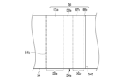
- FIG. 14 is a schematic diagram showing a portion of the outer wrapper as viewed from the direction indicated by the arrow XIV in FIG. 13.
- the wrapper 54 is formed in a cylindrical rod shape with the tip rod 22, tobacco rod 24, and cooling section 14 all having approximately the same diameter, with the tobacco rod 24 adjacent to the downstream side of the tip rod 22 and the cooling section 14 adjacent to the downstream side of the tobacco rod 24, wrapping around the outer circumference.
- the wrapper 54 is provided with a third seam portion 56 in which the ends of the approximately rectangular sheet material are overlapped and bonded with water-based adhesives 57a and 57b to fix the overlapping portion 54a of the wrapper 54.
- the third seam portion 56 does not use a hot melt adhesive that melts when heated.
- the third seam portion 56 is provided along the axial direction of the rod portion 12 in the overlapping portion 54a between the ends of the wrapper 54.
- the third seam portion 56 has a 3-1 region 56a to which a water-based adhesive 57a is applied, and a 3-2 region 56b to which a water-based adhesive 57b is applied, which is provided adjacent to the circumferential outside of the 3-1 region 56a of the overlapping portion 54a of the wrapper 54. Therefore, the seam portion 56 having multiple regions 56a, 56b allows the water-based adhesives 57a, 57b to dry more quickly, and allows the seam portion 56 to obtain an appropriate bonding strength more quickly.
- the 3-1 region 56a and the 3-2 region 56b are each approximately rectangular.
- the water-based adhesives 57a and 57b contain one of ethylene-vinyl acetate copolymer resin (EVA), polyvinyl alcohol (PVA), carboxymethyl cellulose (CMC), and starch paste, or a mixture of at least two of EVA, PVA, CMC, and starch paste.
- EVA ethylene-vinyl acetate copolymer resin
- PVA polyvinyl alcohol
- CMC carboxymethyl cellulose
- starch paste starch paste
- the water-based adhesives 57a and 57b are adhesives whose bonding strength increases as the water in the adhesive evaporates. For this reason, it is expected that the strength of the seam portion 56 will increase by heating to an appropriate temperature using the heater 320 of the device 300, and it is not expected that the strength of the seam portion 56 will decrease. In other words, the wrapper 54 suppresses the decrease in strength of the seam portion 56 when the seam portion 56 is heated.
- the 3-1 region 56a and the 3-2 region 56b are each provided along the axial direction of the rod portion 12.
- the 3-1 region 56a and the 3-2 region 56b are each continuous with water-based adhesives 57a and 57b along the axial direction of the rod portion 12.
- a region free of water-based adhesive (adhesive-free region) 58a is provided along the axial direction of the rod portion 12.
- the circumferential width of the water-based adhesive-free region 58a between the 3-1 region 56a and the 3-2 region 56b, which intersects with the axial direction of the rod portion 12, is preferably 0.1 mm to 2 mm.
- a region 58b without water-based adhesive is formed between the 3-2 region 56b and the end surface 54b of the wrapper 54.
- the circumferential width of the region 58b without water-based adhesive, which intersects with the axial direction of the rod portion 12, is preferably 0.1 mm to 2 mm.
- a water-based adhesive 57a is applied beyond the end face 54c to the outer periphery of the tip rod 22, the tobacco rod 24, and the cooling section 14.
- the tip rod 22, the tobacco rod 24, and the cooling section 14 are bonded to the wrapper 54 by the water-based adhesive 57a.
- the total amount of water-based adhesive 57a in the 3-1 region 56a and the amount of water-based adhesive 57b in the 3-2 region 56b is, for example, 1 mg/120 mm to 5 mg/120 mm. It is preferable that the amount of water-based adhesive 57a in the 3-1 region 56a is greater than the amount of water-based adhesive 57b in the 3-2 region 56b, but they may be the same amount.
- the third seam portion 56 can maintain a fixed state at the overlapping portion 54a even when heated to an appropriate temperature at which aerosol is generated from the filler material 42 of the tobacco rod 24, for example.
- the mouthpiece portion 16 There are no particular limitations on the configuration of the mouthpiece portion 16, so long as it functions as a general filter.
- the mouthpiece section 16 has a first mouthpiece segment 62 and a second mouthpiece segment 64.
- the first mouthpiece segment 62 includes the mouth end Me
- the second mouthpiece segment 64 is adjacent to the tip side of the first mouthpiece segment 62.
- the rear end of the cooling section 14 is adjacent to the tip side of the second segment 62.
- General functions of the mouthpiece 16 include, for example, adjusting the amount of air mixed in when inhaling aerosols, reducing flavors, and reducing nicotine and tar, but it is not necessary for it to have all of these functions. Also, in electrically heated tobacco products, which tend to produce fewer components and have a lower tobacco filler filling rate compared to cigarette products, another important function is to prevent the filler 42 inside the tobacco rod 24 from falling out while suppressing the filtering function.
- the cross section of the mouthpiece portion 16 is substantially circular.
- the diameter of the mouthpiece portion 16 may be changed as appropriate to suit the size of the product, but is preferably approximately the same as that of the rod portion 12. If the cross section is not circular, the above diameter applies to a circle having the same area as the cross section.
- the axial length of the mouthpiece portion 16 may be changed as appropriate to suit the size of the product, but is usually preferably 5 mm or more and 35 mm or less.
- the shape and dimensions of the filter material can be adjusted as appropriate so that the shape and dimensions of the mouthpiece portion 16 are within the above ranges.
- the airflow resistance per 120 mm of axial length of the mouthpiece portion 16 is not particularly limited, but is usually preferably 40 mmH 2 O or more and 300 mmH 2 O or less. It is known that the relationship between the airflow resistance of the mouthpiece portion 16 and the length of the mouthpiece portion 16 is proportional within the normally used length range (lengths of 5 mm to 200 mm), and if the length of the mouthpiece portion 16 is doubled, the airflow resistance also doubles.
- the first mouthpiece segment 62 has a cylindrical cellulose acetate tow filter 72 as a filler, and a sheet-like filter wrapper (roller paper) 74 around which the acetate tow filter 72 is wrapped.
- the density of the acetate tow filter 72 in the mouthpiece portion 16 is not particularly limited, but is preferably in the range of 0.10 g/cm 3 to 0.25 g/cm 3 .
- the single thread fineness and total fineness of the cellulose acetate tow filter 72 are not particularly limited.
- the single thread fineness is preferably 5 to 20 g/9000 m and the total fineness is preferably 12000 to 30000 g/9000 m.
- the mouthpiece portion 16 is formed by filling the cellulose acetate tow filter 72, 5 to 10% by weight of triacetin may be added to the weight of the cellulose acetate tow filter 72 to improve the filter hardness.
- the first mouthpiece segment 62 can use other alternative filters, such as a paper filter filled with sheet-like pulp paper as a filter material.
- the paper filter can be the same as the filler material 32 of the tip rod 22.
- a flavoring may be added to the acetate tow filter 72 of the mouthpiece portion 16.
- the amount of flavoring delivered during use can be increased compared to when the flavoring is added to the tobacco filler 42 constituting the tobacco rod 24.
- the degree of increase in the amount of flavoring delivered can be further increased depending on the position of the opening 14a provided in the cooling portion 14.
- There is no particular restriction on the method of adding the flavoring to the acetate tow filter 72 and it is sufficient that the flavoring is added so that it is dispersed approximately uniformly in the acetate tow filter 72 to which the flavoring is to be added.
- the amount of flavoring added can be 10 to 100 volume % of the acetate tow filter 72.
- the type of flavoring is not particularly limited, but the same flavoring as that contained in the tobacco filler 42 described above may be used.
- Activated carbon may be added to at least a portion of the acetate tow filter 72 of the first mouthpiece segment 62 of the mouthpiece portion 16.
- the mouthpiece portion 16 may contain a capsule that includes a crushable shell such as gelatin inside the acetate tow filter 72 of the first mouthpiece portion 16.
- the form of the capsule is not particularly limited, but may be, for example, a capsule that can be easily broken by the force of the user's fingers, and is preferably spherical in shape.
- the additives contained in the capsule may include any of the additives described above, but in particular, it is preferable to include flavorings and activated carbon.
- the flavorings may be, for example, menthol, spearmint, peppermint, fenugreek, clove, medium chain triglycerides (MCT), etc., or combinations of these.
- the first mouthpiece segment 62 preferably includes a filter wrapper 74 around which the acetate tow filter 72 is wrapped, from the standpoint of improving strength and structural rigidity.
- the form of the filter wrapper 74 is not particularly limited, and may include one or more rows of adhesive-containing seams.
- the adhesive may include both a water-based adhesive and a hot melt adhesive, and the hot melt adhesive may further include polyvinyl alcohol.
- the thickness of the filter wrapper 74 is not particularly limited, and is preferably not less than 20 ⁇ m and not more than 140 ⁇ m.
- the basis weight of the filter wrapper 74 is not particularly limited, and is preferably not less than 20 gsm and not more than 100 gsm.
- the filter wrapper 74 may or may not be coated, but is preferably coated with a desired material from the viewpoint of imparting functions other than strength and structural rigidity.
- the second mouthpiece segment 64 is formed, for example, as a channel filter (hollow segment portion).
- the second mouthpiece segment 64 includes a filling layer 64a having one or more hollow channels.
- the filling layer 64a is made of, for example, fibers, and since the fiber packing density is high, when the user inhales, air and aerosol flow only through the hollow channels and hardly flow through the filling layer 64a itself.
- shortening the length of the first mouthpiece segment 62 and replacing it with the second mouthpiece segment 64 is effective in adjusting the amount of aerosol delivered.
- the mouthpiece portion 16 has two or more segments 62, 64, it is preferable to wrap a sheet-shaped connecting filter wrapper (outer filter wrapper) 66 around the two or more segments 62, 64 in order to connect the segments 62, 64. That is, the mouthpiece portion 16 has a connecting filter wrapper 66 in addition to the two or more segments 62, 64.
- the material of the filter wrapper 66 in the mouthpiece portion 16 is not particularly limited, and a known material can be used, and it may also contain a filler such as calcium carbonate.
- the filter wrapper 66 is made of the same material as the filter wrapper 74 of the first mouthpiece segment 62, and is fixed in the same manner as the filter wrapper 74 of the first mouthpiece segment 62.
- the filter wrapper 66 may be formed by adjoining a hot melt adhesive to a water-based adhesive to form a seam portion, or may be formed by only a water-based adhesive.
- the mouthpiece section 16 may be configured such that the first mouthpiece segment 62 is located on the upstream side and the second mouthpiece segment 64 is located on the downstream side (the side of the mouthpiece end Me).
- the mouthpiece portion 16 may also be preferably formed as shown in FIG. 3B.
- the mouthpiece portion 16 shown in FIG. 3B has a 1-1 mouthpiece segment 62a, a 1-2 mouthpiece segment 62b, a second mouthpiece segment 64, and a sheet-like filter wrapper 66.
- the 1-1 mouthpiece segment 62a has a filler 72a and a sheet-like wrapper 74a.
- the filler 72a is a cellulose acetate tow filter.
- the wrapper 74a is the same as the wrapper 74 described above.
- the first-second mouthpiece segment 62b has a filler 72b and a sheet-like wrapper 74b.
- the filler 72b is a paper filter that is creped (shrunk) and folded to form a roughly cylindrical rod of an appropriate length.
- the wrapper 74b is the same as the wrapper 74 described above.
- the mouthpiece section 16 has the 1-1 mouthpiece segment 62a disposed at the mouth end Me, the 1-2 mouthpiece segment 62b disposed upstream of that, and the second mouthpiece segment 64 disposed further upstream of that, with the 1-1 mouthpiece segment 62a, the 1-2 mouthpiece segment 62b, and the second mouthpiece segment 64 wrapped around the filter wrapper 66.
- the mouthpiece portion 16 can be configured as appropriate.
- the outer periphery of the mouthpiece portion 16 and the cooling portion 14 is covered with tipping paper 18.
- the tip of the tipping paper 18 covers the rear end of the outer wrapper of the outer periphery of the cooling portion 14. The rear end of the tipping paper 18 is aligned with the rear end of the mouthpiece portion 16.
- the material of the tipping paper 18 is not particularly limited, and can be paper made from general plant fibers (pulp), a sheet made from polymer-based chemical fibers (polypropylene, polyethylene, nylon, etc.), a polymer-based sheet, metal foil, or a composite material that combines these.
- the tipping paper 18 can be made from a composite material in which a polymer-based sheet is bonded to a paper base material.
- the tipping paper 18 here refers to a sheet-like material that connects multiple segments in the flavor inhalation article 10, such as connecting the rod portion 12 and the mouthpiece portion 16.
- the tipping paper 18 may have a seam formed by adjoining a water-based adhesive and a hot melt adhesive, or the seam may be formed using only a water-based adhesive.
- the basis weight of the tipping paper 18 is not particularly limited, but is preferably 10 gsm or more and 120 gsm or less.
- the air permeability of the tipping paper 18 is not particularly limited, but is preferably 0 CU or more and 30,000 CU or less.
- the air permeability is a value measured in accordance with ISO 2965:2009, and is expressed as the flow rate (cm 3 ) of gas passing through an area of 1 cm 2 per minute when the differential pressure between both sides of the paper is 1 kPa.
- 1 CU is cm 3 /(min ⁇ cm 2 ) under 1 kPa.
- the chip paper 18 may contain fillers, such as metal carbonates such as calcium carbonate and magnesium carbonate, metal oxides such as titanium oxide, titanium dioxide and aluminum oxide, metal sulfates such as barium sulfate and calcium sulfate, metal sulfides such as zinc sulfide, quartz, kaolin, talc, diatomaceous earth, gypsum, etc., and it is particularly preferable that the chip paper 18 contains calcium carbonate from the viewpoint of improving whiteness and opacity and increasing the heating rate.
- these fillers may be used alone or in combination of two or more types.
- the chip paper 18 may contain a water resistance improver to improve water resistance.
- Water resistance improvers include wet strength agents (WS agents) and sizing agents.
- wet strength agents include urea formaldehyde resin, melamine formaldehyde resin, polyamide epichlorohydrin (PAE), etc.
- sizing agents include rosin soap, alkyl ketene dimer (AKD), alkenyl succinic anhydride (ASA), and highly saponified polyvinyl alcohol with a saponification degree of 90% or more.
- a coating agent may be added to at least one of the two surfaces of the tipping paper 18, the front and back surfaces.
- the coating agent There are no particular limitations on the coating agent, but a coating agent that can form a film on the surface of the paper and reduce the permeability to liquids is preferred.
- the chipping paper 18 has openings 18a for taking in air from the outside.
- the openings 18a in the chipping paper 18 are created together with the openings 14a in the cooling section 14. Therefore, the openings 18a in the chipping paper 18 are connected to the openings 14a in the cooling section 14.
- the tipping paper 18 has an opening 18a directly above (at a vertically overlapping position) the opening 14a provided in the cooling section 14. For this reason, after wrapping and connecting the tobacco rod 24, the cooling section 14, and the mouthpiece section 16 with the tipping paper 18, a laser beam may be irradiated from above the tipping paper 18 so as to penetrate the tipping paper 18 and the cooling section 14, to provide the openings 14a and 18a.
- the number of the openings 18a in the tipping paper 18 is not particularly limited. In this embodiment, a plurality of openings 18a are arranged at regular intervals in the circumferential direction of the tipping paper 18.
- the group of openings 18a arranged in the circumferential direction of the tipping paper 18 may be formed in a plurality of stages along the axial direction of the tipping paper 18.
- the vapor containing the aerosol generating base material and the tobacco flavor components is condensed by being cooled by the low-temperature air introduced into the tipping paper 18 through the openings 18a.
- This promotes the generation of aerosols and allows the size of the aerosol particles to be controlled.
- a polymer coating such as polyvinyl alcohol or a polysaccharide coating such as pectin
- the cooling effect can be increased by utilizing the heat absorption of the coating or the heat of dissolution associated with the phase change.
- the airflow resistance of this cylindrical cooling segment is zero mmH2O .
- each flavor inhalation article 10 configured as described above is not particularly limited, but is preferably 10 mmH 2 O or more and 100 mmH 2 O or less from the viewpoint of ease of inhalation.
- the airflow resistance is measured, for example, using a filter airflow resistance measuring device manufactured by Cerulean Co., Ltd., in accordance with the ISO standard method (ISO6565:2015).
- the airflow resistance refers to the air pressure difference between the first end face and the second end face when air is flowed at a predetermined air flow rate (17.5 cc/min) from one end face (first end face) to the other end face (second end face) in a state in which air does not pass through the side face of the flavor inhalation article 10.
- the unit is generally expressed in mmH 2 O. It is known that the relationship between the airflow resistance and the flavor inhalation article 10 is proportional within the length range typically used (lengths of 5 mm to 200 mm), and if the length of the flavor inhalation article 10 is doubled, the airflow resistance also doubles.
- w is the width (outer diameter) of the tip De of the flavor inhalation article 10
- h is the axial length of the flavor inhalation article 10
- the cross-sectional shape of the flavor inhalation article 10 is not particularly limited, and may be a polygon, a rounded polygon, a circle, an ellipse, or the like.
- the width w of the flavor inhalation article 10 is the diameter when the cross-sectional shape of the flavor inhalation article 10 is a circle, the major axis when the cross-sectional shape is an ellipse, and the diameter of the circumscribed circle or the major axis of the circumscribed ellipse when the cross-sectional shape is a polygon or a rounded polygon.
- the axial length h of the flavor inhalation article 10 is not particularly limited, and is preferably, for example, usually 40 mm or more and usually 100 mm or less.
- the width w of the tip De of the flavor inhalation article 10 is not particularly limited, and is preferably, for example, usually 5 mm or more and usually 10 mm or less.
- the ratio of the length of the cooling section 14 to the length of the mouthpiece section 16 (cooling section 14:mouthpiece section 16) in the length of the flavor inhalation article 10 is not particularly limited, but is usually preferably 0.60 to 1.40:0.60 to 1.40 from the viewpoint of the amount of flavor delivered and the appropriate aerosol temperature.
- the operation of the flavor inhalation system 200 according to this embodiment will now be described.
- the flavor inhalation article 10 is used at least a few days after it is manufactured, and appropriate peel strength is ensured at the seams of the wrappers 34, 44, 54, 74, and 66 and the tipping paper 18. In other words, the flavor inhalation article 10 maintains its shape during normal use.
- the tip rod 22 side of the flavor inhalation article 10 is inserted into the storage section 311 of the device 300.
- the heated area A1 by the heater 320 covers the entire outer periphery of the tip rod 22 and the tobacco rod 24 of the flavor inhalation article 10.
- the non-heated area A2 by the heater 320 covers part of the outer periphery of the cooling section 14 of the flavor inhalation article 10. Note that part of the heated area A1 may cover part of the outer periphery of the cooling section 14.
- the control section 370 uses power from the power source 380 to heat the heater 320 to a predetermined temperature.
- the heater 320 heats a portion of each of the first seam portion 36, the second seam portion 46, and the third seam portion 56 in the heating region A1.
- the smoking taste deteriorates compared to before the hot melt adhesive melts.
- the first seam portion 36, the second seam portion 46, and the third seam portion 56 do not contain a hot melt adhesive. Therefore, even if the first seam portion 36, the second seam portion 46, and the third seam portion 56 of the flavor inhalation article 10 are heated, deterioration of the smoking taste is suppressed.
- the water-based adhesives 37a, 37b of the first seam portion 36, the water-based adhesives 47a, 47b of the second seam portion 46, and the water-based adhesives 57a, 57b of the third seam portion 56 do not melt even when heated by the heater 320. This makes it possible to prevent the water-based adhesives 37a, 37b, 47a, 47b, 57a, 57b from adhering to the storage portion 311 of the device 300. This makes it possible to reduce the number of maintenance operations for the storage portion 311 of the device 300 compared to when a hot melt adhesive is used.
- a rod portion for a flavor inhalation article, a non-combustion type flavor inhalation article, and a non-combustion type flavor inhalation system that can suppress a decrease in strength of the seam portion when the seam portion of the wrapper of a tobacco rod or the like of the flavor inhalation article is heated. Furthermore, according to this embodiment, it is possible to suppress adhesion of molten adhesive, glue, etc. from the rod portion for the flavor inhalation article to a device having a heater.
- first seam portion 36 has two regions 36a, 36b
- second seam portion 46 has two regions 46a, 46b
- third seam portion 56 has two regions 56a, 56b.
- one or two of the first seam portion 36, the second seam portion 46, and the third seam portion 56 may be fixed with a water-based adhesive only in one region.
- the overlapping portion may be fixed with a line of water-based adhesive along the axial direction of the rod portion 12.
- the water-based adhesive 37a in the 1-1 region 36a is a so-called solid coating
- the water-based adhesive 37b in the 1-2 region 36b is a so-called solid coating
- water-based adhesives 37b1 and 37b2 are applied in multiple rows in the 1-2 region 36b.
- the water-based adhesive 37b1 is continuous along the axial direction of the rod portion 12.
- the water-based adhesive 37b2 is continuous along the axial direction of the rod portion 12.
- These water-based adhesives 37b1, 37b2 may remain in multiple rows in the first-second region 36b, or may be mixed together.
- the amounts of these water-based adhesives 37b1, 37b2 may be the same, or may differ. If there is a difference, for example, the amount of water-based adhesive 37b2 on the outer circumferential side may be more than the amount of water-based adhesive 37b1 on the inner circumferential side, or vice versa.
- the combined amount of the water-based adhesives 37b1 and 37b2 may be greater than the amount of the water-based adhesive 37a in the 1-1 region 36a. In this case, by making the amount of either the water-based adhesive 37b1 or 37b2 less than the amount of the water-based adhesive 37a in the 1-1 region 36a, the water-based adhesive 37b1 or the water-based adhesive 37b2 dries sooner than the water-based adhesive 37a in the 1-2 region 36b, allowing the fixation of the overlapping portion 34a to be achieved sooner.
- water-based adhesive 37a may be applied in multiple rows in the 1-1 region 36a as well.
- multiple rows of water-based adhesive may be applied to at least one of the water-based adhesive 37a in the 1-1 region 36a and the water-based adhesive 37b in the 1-2 region 36b.
- water-based adhesive 37b in the 1-2 region 36b can also be used as the water-based adhesive 47b in the 2-2 region 46b of the wrapper 44, the water-based adhesive 57b in the 3-2 region 56b of the outer wrapper 54, etc.
- a plurality of water-based adhesives 37b are applied discretely, for example at predetermined intervals, along the axial direction of the rod portion 12. These water-based adhesives 37b may remain discrete or may be mixed together in the 1-2 region 36b.
- water-based adhesive 37b in the 1-2 region 36b can also be used as the water-based adhesive 47b in the 2-2 region 46b of the wrapper 44, the water-based adhesive 57b in the 3-2 region 56b of the outer wrapper 54, etc.
- a plurality of water-based adhesives 37b are applied, for example at predetermined intervals, along the axial direction of the rod portion 12.
- the plurality of water-based adhesives 37b are arranged in a staggered manner along the axial direction of the rod portion 12, with those closer to the circumferential inner end face 34c of the wrapper 34 and those closer to the circumferential outer end face 34b of the wrapper 34.
- the water-based adhesives 37b may remain discrete or may be mixed together.
- water-based adhesive 37b in the 1-2 region 36b can also be used as the water-based adhesive 47b in the 2-2 region 46b of the wrapper 44, the water-based adhesive 57b in the 3-2 region 56b of the outer wrapper 54, etc.
- a plurality of water-based adhesives 37b are applied, for example, at appropriate intervals along the axial direction of the rod portion 12.
- the plurality of water-based adhesives 37b are arranged as a set along the axial direction of the rod portion 12, such as one closer to the inner end face 34c of the wrapper 34 in the circumferential direction, one arranged between the inner end face 34c of the wrapper 34 and the outer end face 34b of the wrapper 34 in the circumferential direction, and one closer to the outer end face 34b in the circumferential direction of the wrapper 34.
- a plurality of sets of these water-based adhesives 37b are arranged along the axial direction of the rod portion 12. In the 1-2 region 36b, these water-based adhesives 37b may remain discrete or may be mixed together.
- water-based adhesive 37b in the 1-2 region 36b can also be used as the water-based adhesive 47b in the 2-2 region 46b of the wrapper 44, the water-based adhesive 57b in the 3-2 region 56b of the outer wrapper 54, etc.
- the fixing structure (connection structure) of the first seam portion 36, the second seam portion 46, and the third seam portion 56 of the flavor inhalation article 10 has multiple regions in a direction intersecting the axial direction of the rod portion 12, and a structure in which these multiple regions are aligned along the axial direction of the rod portion 12 and a structure in which one region is aligned along the axial direction of the rod portion 12 are appropriately selected.
- the present invention is not limited to the above-described embodiments, and can be modified in various ways during implementation without departing from the gist of the invention.
- the embodiments may also be implemented in appropriate combination, in which case the combined effects can be obtained.
- the above-described embodiments include various inventions, and various inventions can be extracted by combinations selected from the multiple constituent elements disclosed. For example, if the problem can be solved and an effect can be obtained even if some constituent elements are deleted from all the constituent elements shown in the embodiments, the configuration from which these constituent elements are deleted can be extracted as an invention.
- a rod portion for a flavor inhalation article A filler material; A wrapper formed in a sheet shape and covering the outer periphery of the filler; a first seam portion that fixes the overlapping portion of the wrapper, the first seam portion having a first-1 region made of a water-based adhesive and disposed along the axial direction of the rod portion in the overlapping portion between the ends of the wrapper, and a first-2 region made of a water-based adhesive and disposed adjacent to the circumferential outside of the first-1 region in the overlapping portion of the wrapper; having The first seam portion does not use a hot melt adhesive that melts when heated.
- a rod portion for a flavor inhalation article A filler material; A wrapper formed in a sheet shape and covering the outer periphery of the filler; a first seam portion that fixes the overlapping portion of the wrapper, the first seam portion having a first-1 region made of a water-based adhesive and disposed along the axial direction of the rod portion in the overlapping portion between the ends of the wrapper,
- the first-2 region is provided along the axial direction of the rod portion.
- the amount of the water-based adhesive in the 1-1 region is greater than the amount of the water-based adhesive in the 1-2 region.
- the amount of the water-based adhesive in the 1-1 region and the 1-2 region is 1 mg/120 mm to 5 mg/120 mm;
- the circumferential width of the region free of the water-based adhesive intersecting with the axial direction of the rod portion is 0.1 mm to 2 mm.
- the circumferential width of the first seam portion intersecting the axial direction of the rod portion is 1 mm to 3 mm.
- the distance between the first-2 region of the wrapper and the outer end surface of the overlapping portion in the circumferential direction is greater than 0 mm and less than 2 mm;
- the filler includes at least one of a sheet material formed of paper, a nonwoven fabric or a resin material, cellulose acetate, cut tobacco, and sheet tobacco.
- the water-based adhesive comprises one of ethylene-vinyl acetate copolymer resin (EVA), polyvinyl alcohol (PVA), carboxymethyl cellulose (CMC), and starch paste, or a mixture of at least two of the EVA, the PVA, the CMC, and the starch paste;
- EVA ethylene-vinyl acetate copolymer resin
- PVA polyvinyl alcohol
- CMC carboxymethyl cellulose
- starch paste or a mixture of at least two of the EVA, the PVA, the CMC, and the starch paste
- a rod portion for a flavor inhalation article according to any one of claims 1 to 9.
- a rod portion for a flavor inhalation article according to any one of claims 1 to 10, which is disposed in or near a heated portion; A cooling section provided downstream of the rod section; A mouthpiece portion provided downstream of the cooling portion; and a sheet-like outer wrapper connecting the outer periphery of the rod portion and the cooling portion.
- a second seam portion provided along the axial direction of the rod portion in the overlapping portion between the ends of the outer wrapper, the second seam portion having an area of water-based adhesive and fixing the overlapping portion of the outer wrapper; The second seam portion does not use a hot melt adhesive that melts when heated.
- the second seam portion is provided along the axial direction of the rod portion in the overlapping portion between the ends of the outer wrapper, and has a second-1 region formed of a water-based adhesive, and a second-2 region formed adjacent to the circumferential outside of the second-1 region in the overlapping portion of the outer wrapper, and is formed of a water-based adhesive.
- the rod portion has a tip rod disposed on the opposite side of the non-combustion type flavor inhalation article from the mouthpiece portion, and a tobacco rod provided between the tip rod and the cooling portion.
- a non-combustion type flavor inhalation article according to any one of claims 11 to 13, a housing portion that houses the outer side of the rod portion of the non-combustion type flavor inhalation article;
- a non-combustion type flavor inhalation system comprising: a device having a heater provided in the storage section and configured to heat an outer periphery of the rod section.
- the filling material includes an aerosol-generating substrate that generates an aerosol when heated by the heater.
- a non-combustion type flavor inhalation system as described in appendix 14.
- a non-combustion type flavor inhalation article according to claim 13; a housing portion for housing the tip rod and the tobacco rod of the non-combustion type flavor inhalation article; a heater provided in the storage section and configured to heat at least the outer side of the tobacco rod among the tip rod and the outer side of the tobacco rod; and a device having the heater.
- the filler of the tobacco rod includes an aerosol-generating substrate that generates an aerosol when heated by the heater.
- a non-combustion type flavor inhalation system as described in appendix 16.
Landscapes
- Cigarettes, Filters, And Manufacturing Of Filters (AREA)
- Manufacture Of Tobacco Products (AREA)
- Adhesives Or Adhesive Processes (AREA)
Priority Applications (5)
| Application Number | Priority Date | Filing Date | Title |
|---|---|---|---|
| PCT/JP2023/026437 WO2025017876A1 (ja) | 2023-07-19 | 2023-07-19 | 香味吸引物品用のロッド部、非燃焼型香味吸引物品、非燃焼型香味吸引システム |
| JP2025533805A JPWO2025017876A1 (https=) | 2023-07-19 | 2023-07-19 | |
| CN202380100412.XA CN121568615A (zh) | 2023-07-19 | 2023-07-19 | 用于风味吸入制品的杆件部分、非燃烧型风味吸入制品、以及非燃烧型风味吸入系统 |
| KR1020267000892A KR20260022432A (ko) | 2023-07-19 | 2023-07-19 | 향미 흡입 물품을 위한 막대 부분, 비연소식 향미 흡입 물품, 및 비연소식 향미 흡입 시스템 |
| TW113125533A TW202508470A (zh) | 2023-07-19 | 2024-07-08 | 香味吸嚐物品用桿部、非燃燒型香味吸嚐物品、非燃燒型香味吸嚐系統 |
Applications Claiming Priority (1)
| Application Number | Priority Date | Filing Date | Title |
|---|---|---|---|
| PCT/JP2023/026437 WO2025017876A1 (ja) | 2023-07-19 | 2023-07-19 | 香味吸引物品用のロッド部、非燃焼型香味吸引物品、非燃焼型香味吸引システム |
Publications (1)
| Publication Number | Publication Date |
|---|---|
| WO2025017876A1 true WO2025017876A1 (ja) | 2025-01-23 |
Family
ID=94281308
Family Applications (1)
| Application Number | Title | Priority Date | Filing Date |
|---|---|---|---|
| PCT/JP2023/026437 Pending WO2025017876A1 (ja) | 2023-07-19 | 2023-07-19 | 香味吸引物品用のロッド部、非燃焼型香味吸引物品、非燃焼型香味吸引システム |
Country Status (5)
| Country | Link |
|---|---|
| JP (1) | JPWO2025017876A1 (https=) |
| KR (1) | KR20260022432A (https=) |
| CN (1) | CN121568615A (https=) |
| TW (1) | TW202508470A (https=) |
| WO (1) | WO2025017876A1 (https=) |
Citations (4)
| Publication number | Priority date | Publication date | Assignee | Title |
|---|---|---|---|---|
| WO2017104079A1 (ja) | 2015-12-18 | 2017-06-22 | 日本たばこ産業株式会社 | 喫煙物品およびフィルター |
| JP2019126290A (ja) * | 2018-01-24 | 2019-08-01 | 日本製紙パピリア株式会社 | 非燃焼型香味吸引器のカートリッジ成形紙 |
| JP2022542793A (ja) * | 2019-08-02 | 2022-10-07 | フィリップ・モーリス・プロダクツ・ソシエテ・アノニム | リテーナを備えたエアロゾル発生物品 |
| WO2022259505A1 (ja) * | 2021-06-11 | 2022-12-15 | 日本たばこ産業株式会社 | 先端部にキャップ部材を備える香味源含有ロッド |
-
2023
- 2023-07-19 KR KR1020267000892A patent/KR20260022432A/ko active Pending
- 2023-07-19 JP JP2025533805A patent/JPWO2025017876A1/ja active Pending
- 2023-07-19 CN CN202380100412.XA patent/CN121568615A/zh active Pending
- 2023-07-19 WO PCT/JP2023/026437 patent/WO2025017876A1/ja active Pending
-
2024
- 2024-07-08 TW TW113125533A patent/TW202508470A/zh unknown
Patent Citations (4)
| Publication number | Priority date | Publication date | Assignee | Title |
|---|---|---|---|---|
| WO2017104079A1 (ja) | 2015-12-18 | 2017-06-22 | 日本たばこ産業株式会社 | 喫煙物品およびフィルター |
| JP2019126290A (ja) * | 2018-01-24 | 2019-08-01 | 日本製紙パピリア株式会社 | 非燃焼型香味吸引器のカートリッジ成形紙 |
| JP2022542793A (ja) * | 2019-08-02 | 2022-10-07 | フィリップ・モーリス・プロダクツ・ソシエテ・アノニム | リテーナを備えたエアロゾル発生物品 |
| WO2022259505A1 (ja) * | 2021-06-11 | 2022-12-15 | 日本たばこ産業株式会社 | 先端部にキャップ部材を備える香味源含有ロッド |
Also Published As
| Publication number | Publication date |
|---|---|
| CN121568615A (zh) | 2026-02-24 |
| TW202508470A (zh) | 2025-03-01 |
| KR20260022432A (ko) | 2026-02-19 |
| JPWO2025017876A1 (https=) | 2025-01-23 |
Similar Documents
| Publication | Publication Date | Title |
|---|---|---|
| JP7313437B2 (ja) | 非燃焼加熱式たばこ及び電気加熱式たばこ製品 | |
| JP7627800B2 (ja) | 非燃焼加熱式たばこ製品 | |
| JP7522864B2 (ja) | 非燃焼加熱式たばこ及び電気加熱式たばこ製品 | |
| JP7615181B2 (ja) | 非燃焼加熱式たばこ製品 | |
| WO2025017876A1 (ja) | 香味吸引物品用のロッド部、非燃焼型香味吸引物品、非燃焼型香味吸引システム | |
| WO2025017875A1 (ja) | 非燃焼型香味吸引物品、及び、非燃焼型香味吸引システム | |
| JP7522863B2 (ja) | 非燃焼加熱式たばこ及び電気加熱式たばこ製品 | |
| JP7659576B2 (ja) | 非燃焼加熱式たばこ及び電気加熱式たばこ製品 | |
| JP7640582B2 (ja) | 非燃焼加熱式たばこ及び電気加熱式たばこ製品 | |
| EP4691280A1 (en) | Non-combustion type flavor inhalation article and non-combustion type flavor inhalation system | |
| WO2025186891A1 (ja) | 香味発生物品 | |
| TW202525179A (zh) | 香味產生物品 | |
| JP2025135077A (ja) | 香味発生物品 | |
| WO2023100295A1 (ja) | 非燃焼加熱型スティック | |
| WO2025203565A1 (ja) | 香味発生物品および香味発生システム | |
| WO2025052625A1 (ja) | 香味発生物品 | |
| WO2024189732A1 (ja) | 香味スティック及び非燃焼型香味吸引システム | |
| WO2025243507A1 (ja) | 香味発生物品および香味発生システム | |
| WO2025052617A1 (ja) | 香味発生物品 | |
| WO2025154253A1 (ja) | 香味発生物品 | |
| WO2025052618A1 (ja) | 香味発生物品及び喫煙システム | |
| WO2025186899A1 (ja) | 香味吸引物品 | |
| WO2025052613A1 (ja) | 香味発生物品および香味発生システム | |
| WO2025052620A1 (ja) | 香味発生物品 |
Legal Events
| Date | Code | Title | Description |
|---|---|---|---|
| 121 | Ep: the epo has been informed by wipo that ep was designated in this application |
Ref document number: 23945879 Country of ref document: EP Kind code of ref document: A1 |
|
| ENP | Entry into the national phase |
Ref document number: 2025533805 Country of ref document: JP Kind code of ref document: A |
|
| WWE | Wipo information: entry into national phase |
Ref document number: 2025533805 Country of ref document: JP |
|
| ENP | Entry into the national phase |
Ref document number: 1020267000892 Country of ref document: KR Free format text: ST27 STATUS EVENT CODE: A-0-1-A10-A15-NAP-PA0105 (AS PROVIDED BY THE NATIONAL OFFICE) |
|
| WWE | Wipo information: entry into national phase |
Ref document number: 1020267000892 Country of ref document: KR |
|
| WWE | Wipo information: entry into national phase |
Ref document number: 2023945879 Country of ref document: EP |
|
| WWP | Wipo information: published in national office |
Ref document number: 1020267000892 Country of ref document: KR |
|
| NENP | Non-entry into the national phase |
Ref country code: DE |