WO2025013920A1 - 酸化物材料 - Google Patents
酸化物材料 Download PDFInfo
- Publication number
- WO2025013920A1 WO2025013920A1 PCT/JP2024/025126 JP2024025126W WO2025013920A1 WO 2025013920 A1 WO2025013920 A1 WO 2025013920A1 JP 2024025126 W JP2024025126 W JP 2024025126W WO 2025013920 A1 WO2025013920 A1 WO 2025013920A1
- Authority
- WO
- WIPO (PCT)
- Prior art keywords
- film
- mqo
- crystal structure
- immersed
- group
- Prior art date
- Legal status (The legal status is an assumption and is not a legal conclusion. Google has not performed a legal analysis and makes no representation as to the accuracy of the status listed.)
- Pending
Links
Images




Classifications
-
- Y—GENERAL TAGGING OF NEW TECHNOLOGICAL DEVELOPMENTS; GENERAL TAGGING OF CROSS-SECTIONAL TECHNOLOGIES SPANNING OVER SEVERAL SECTIONS OF THE IPC; TECHNICAL SUBJECTS COVERED BY FORMER USPC CROSS-REFERENCE ART COLLECTIONS [XRACs] AND DIGESTS
- Y02—TECHNOLOGIES OR APPLICATIONS FOR MITIGATION OR ADAPTATION AGAINST CLIMATE CHANGE
- Y02E—REDUCTION OF GREENHOUSE GAS [GHG] EMISSIONS, RELATED TO ENERGY GENERATION, TRANSMISSION OR DISTRIBUTION
- Y02E60/00—Enabling technologies; Technologies with a potential or indirect contribution to GHG emissions mitigation
- Y02E60/10—Energy storage using batteries
Definitions
- This disclosure relates to oxide materials.
- Non-Patent Document 1 proposes a method for converting 12 types of Ti compounds, including harmless precursors (TiC, TiN, etc.) that are abundant on Earth, into TiO2 - based one-dimensional (1D) nanofilaments (NFs). It has also been shown that the TiO2 -based one-dimensional (1D) nanofilaments (NFs) can be applied in fields such as photocatalysis, dye decomposition, batteries, and supercapacitors.
- the TiO2- based one-dimensional (1D) nanofilaments have the instability that the crystal structure changes when exposed to physical stimuli such as laser light and heat. If the crystal structure changes, it is thought that the function to be expressed will change. For example, in the case of TiCO, when the light intensity is increased by applying a laser light with a wavelength of 532 nm or when the temperature is raised to 500 ° C, the Raman spectrum changes, and the crystal structure changes from lepidocrocite type to anatase type based on the spectrum assignment.
- the crystal structure of lepidocrocite type is preferable because it has a larger effective interlayer and specific surface area than the anatase type, and has a higher adsorption amount, catalytic activity, and ion conductivity. Therefore, an oxide material that has a lepidocrocite type crystal structure and can maintain the lepidocrocite type without changing the crystal structure even when exposed to the above-mentioned laser light or when heated to 500 ° C is desired.
- the present disclosure has been made in consideration of the above circumstances, and its purpose is to provide an oxide material whose crystal structure is lepidocrocite type, and which can maintain the lepidocrocite type without changing its crystal structure even when irradiated with strong laser light or heated to a high temperature of 500°C.
- a compound of the formula: MQ a O b (wherein M is at least one element selected from the group consisting of Groups 3, 4, 5, 6 and 7; Q is at least one element selected from the group consisting of Groups 12, 13, 14, 15, and 16 (excluding O); a is 0 to 2, b is greater than 0 and less than or equal to 2;
- the nanofiber, the nanowire, and the two-dimensional material are at least one selected from the group consisting of: containing a metal element and/or a metalloid element on the surface and/or between the layers, An oxide material is provided having a total halogen element content of 0.90 wt. % or less.
- an oxide material that maintains its lepidocrocite structure without changing its crystal structure, even when the light intensity is increased by irradiating it with a 532 nm laser light, or when the temperature is raised to 500°C.
- FIG. 2 is a schematic explanatory diagram illustrating the form of a material according to the present embodiment.
- FIG. 2 is a schematic explanatory diagram illustrating another embodiment of the material according to the present embodiment.
- FIG. 2 is a schematic explanatory diagram illustrating another embodiment of the material according to the present embodiment.
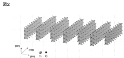
- FIG. 2 is an explanatory diagram of a representative atomic model of the material of the present embodiment.
- FIG. 2 is another explanatory diagram of a representative atomic model of the material of the present embodiment.
- FIG. 2 is another explanatory diagram of a representative atomic model of the material of the present embodiment.
- FIG. 1 is an illustration of a representative atomic model of an anatase type material.
- FIG. 2 is another explanatory diagram of a representative atomic model of the material of the present embodiment.
- FIG. 2 is another explanatory diagram of a representative atomic model of the material of the present embodiment.
- 1 shows the results of Raman spectroscopic analysis of a film after laser irradiation at each light intensity in Example 1.
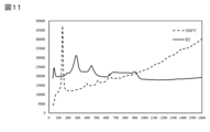
- 1 shows the results of Raman spectroscopic analysis of a film heated to 500° C. in Example 1.
- 1 shows the results of Raman spectroscopy of a film heated to 500° C. in Example 2.
- 1 shows the results of Raman spectroscopy of a film heated to 500° C. in Comparative Example 1.
- 13 shows the results of Raman spectroscopic analysis of a film after laser irradiation at each light intensity in Comparative Example 6.
- This embodiment relates to an oxide material that includes one or more selected from the group consisting of nanofibers, nanowires, and two-dimensional materials of a specific material, includes a metal element and/or a metalloid element on the surface and/or between layers, and has a total content of halogen elements of 0.90 mass% or less.
- a material when simply referring to a "material”, it means "a material including one or more selected from the group consisting of nanofibers, nanowires, and two-dimensional materials” (in other words, a material including at least one selected from the group consisting of nanofibers, nanowires, and two-dimensional materials).
- an "oxide material” it means a compound consisting of oxygen and other elements.
- a material including one or more selected from the group consisting of nanofibers, nanowires, and two-dimensional materials typically means a material that is a solid content and does not include a binder, etc. (e.g., a polymer).
- a material containing one or more selected from the group consisting of nanofibers, nanowires, and two-dimensional materials may mean, in a narrow sense, a material that is substantially composed of one or more selected from the group consisting of nanofibers, nanowires, and two-dimensional materials (which may contain other objects, impurities, etc. that may be inevitably mixed in).
- materials containing one or more selected from the group consisting of nanofibers, nanowires, and two-dimensional materials are not limited to these.
- the material of this embodiment is one or more selected from the group consisting of nanofibers, nanowires, and two-dimensional materials of a predetermined material (substance).
- the predetermined material that can be used in this embodiment is represented by the following formula (1).
- M is at least one element selected from the group consisting of groups 3, 4, 5, 6 and 7, and may include at least one element selected from the group consisting of so-called early transition metals, such as Sc, Ti, Zr, Hf, V, Nb, Ta, Cr, Mo and Mn, and preferably at least one element selected from the group consisting of Ti, V, Cr, Mo and Mn;
- Q is at least one element selected from the group consisting of Groups 12, 13, 14, 15 and 16 (excluding O), and may include, for example, at least one element selected from the group consisting of B, C, N, Si, P and S; a is 0 to 2, b is greater than 0 and less than or equal to 2;
- MQO predetermined material
- MQO predetermined material
- examples of MQO include those represented by formulas such as TiO2 , TiCO, TiCON, VO2 , VCO, VCON, CrO2 , CrCO, CrCON, MoO2 , MoCO, MoCON, MnO2 , MnCO, and MnCON.
- the M may be Ti and the Q may be C.
- the a may not be 0.
- MQO has a crystal structure that is different from the hexagonal system.
- the crystal structure of MQO can be considered to be anatase type or lepidocrocite type, or a mixture of these at present.
- it is preferable that the crystal structure of MQO is lepidocrocite type.
- MQO can be produced, for example, using a first raw material and a second raw material as follows.
- the first raw material contains at least the above-mentioned M
- the second raw material contains at least the above-mentioned Q
- the first raw material and the second raw material can react in a protic solvent to produce MQO.
- a material represented by the following formula (2) can be used as the first raw material.
- M c A 1 d ...(2) (wherein M is as defined above, A1 is at least one element selected from the group consisting of Groups 12, 13, 14, 15 and 16, and may include, for example, at least one element selected from the group consisting of B, C, N, O, Si, P and S; c and d are each independently 1 to 5.
- the material represented by formula (2) must be different from the product MQO.
- the material represented by formula (2) may typically have no peak in an X-ray diffraction (XRD) pattern in the range of a diffraction angle 2 ⁇ of 2° or more and 12° or less.
- XRD X-ray diffraction
- Examples of the first raw material represented by formula (2) include TiB2 , TiB, TiC, TiN, TiO2 , Ti5Si3 , Ti2SbP , VO2 , V2O4 , NbC , Nb2O5 , MoO2, MoO3 , MoS2 , MnO2 , Mn3O4 , MnCO3 , etc.
- a material represented by the following formula (3) may be used as the first raw material.
- M m A 2 X n ...(3) (wherein M is as defined above, X is at least one element selected from the group consisting of C and N; n is 1 or more and 4 or less, m is greater than n and is less than or equal to 5;
- A2 is at least one element selected from the group consisting of Groups 12, 13, 14, 15 and 16, usually Group A elements, typically Groups IIIA and IVA, and more specifically may include at least one element selected from the group consisting of Al, Ga, In, Tl, Si, Ge, Sn, Pb, P, As, S and Cd, and is preferably Al.
- the MAX phase has a crystal structure in which a layer composed of A2 atoms is located between two layers represented by MmXn (each X may have a crystal lattice located in the octahedral array of M ) .
- MmXn layers a layer of A2 atoms
- A2 atomic layer is located as the layer next to the n+1th layer of M atoms.
- the MAX phase is not limited thereto.
- Examples of the first raw material represented by formula (3) include Ti 3 AlC 2 , Ti 3 GaC 2 , Ti 3 SiC 2 , and the like.
- a material represented by formula (2) and a material represented by formula (3) may be used together (e.g., as a mixture).
- an ionically bondable substance having a carbon-containing group may be used as the second raw material.
- the ionically bondable substance having a carbon-containing group contains C.
- Examples of ionically bondable substances include ammonium salts, phosphates, sulfates, etc.
- a quaternary ammonium salt may be used as the second raw material.
- quaternary ammonium salts include tetramethylammonium hydroxide (TMAH), tetraethylammonium hydroxide (TEAH), tetrapropylammonium hydroxide (TPAH), tetrabutylammonium hydroxide (TBAH or TBAOH), benzyltrimethylammonium hydroxide, tetrabutylammonium fluoride (TBAF), tetrabutylammonium chloride (TBAC1), tetrabutylammonium bromide (TBAB), tetrabutylammonium iodide (TBAI), benzyltriethylammonium chloride (BTEAC), hexadecyltrimethylammonium bromide, cetyltrimethylammonium bromide (CTAB), benzethonium chloride, benzalkonium chloride
- the protic solvent may be any solvent capable of at least partially dissolving the first and second raw materials, and may in particular be an aqueous solvent.
- protic solvents include water, alcohols (e.g., ethanol, 1-propanol, isopropanol), and carboxylic acids (e.g., acetic acid and formic acid).
- the aqueous solvent may be composed of water and, in some cases, a liquid substance compatible with water (e.g., a protic solvent other than water), and is preferably water.
- the first raw material and the second raw material are reacted in a protic solvent.
- the second raw material may be added to the protic solvent in advance.
- the ratio of the second raw material to the total of the protic solvent and the second raw material may be, for example, 5% by mass or more, particularly 20% by mass or more, and/or, for example, 80% by mass or less, particularly 50% by mass or less.
- the first raw material may be further added to the protic solvent to which the second raw material has been added, and mixed. In such a mixture, a reaction to produce MQO proceeds.
- the temperature (reaction temperature) of the mixture (which may contain the reaction product) may be, for example, 15° C. or more, particularly 40° C. or more, and/or, for example, 100° C.
- the mixing time may be, for example, 1 day or more, particularly 2 days or more, and/or, for example, 10 days or less, particularly 7 days or less.
- the mixing may be performed, for example, by rotating and stirring a magnetic stirrer placed in a container using a magnetic stirrer while maintaining the reaction temperature using a hot plate stirrer and a warm water bath.
- the treatment operations and conditions that can cause the reaction to proceed are not limited to those described above and may be selected appropriately depending on the first raw material, the second raw material, the protic solvent, etc. used.
- FIGS. 1A to 1C are schematic diagrams illustrating the form of the material of this embodiment.
- the resulting MQO nanofibers may be in the form of nanoribbons extending in a nanoscale width (width in the [001] direction in FIG. 1A) (extending in the [100] direction in FIG. 1A), for example, as shown in FIG. 1A.
- multiple MQO nanofibers (or nanoribbons) may be bonded and/or integrated with each other to grow into nanoflakes extending in two dimensions.
- multiple MQO nanoflakes may overlap each other (e.g., by van der Waals forces) to form a laminate, as shown in FIG. 1B.
- the nanoflakes may grow into layered nanoflakes extending in two dimensions.
- the higher-order structure may be a porous body (e.g., a particle shape or a membrane shape) in which layered nanofibers are entangled with each other, or a layered structure in which layered nanoflakes are stacked in the thickness direction.
- the generation and growth of such MQO may be considered to be due to a bottom-up synthesis reaction.
- the mixture after the reaction (also called the reaction mixture) may be subjected to post-treatment as appropriate.
- post-treatment include washing, impact (including shear force), drying (e.g. freeze-drying, heat drying), and pulverization.
- Washing may be performed using a protic solvent.
- the protic solvent may be washed, for example, with water or alcohol.
- a separation operation centrifugation and/or decantation
- the washing and separation operations may be repeated until the pH of the supernatant after centrifugation is, for example, 8 or less.
- washing may be performed using an aqueous solution of a metal salt.
- the metal salt may be, for example, a hydroxide of an alkali metal (Li, Na, K, etc.) or a hydroxide of an alkaline earth metal (Mg, Ca, Sr, etc.), typically NaOH, LiOH, KOH, etc.
- washing may be performed using, for example, an aqueous solution of a metal salt with a molar concentration of 0.01 to 10.
- a separation operation centrifugation and/or decantation
- washing and separation operations may be repeated as necessary until the pH of the supernatant after centrifugation is, for example, 8 or less.
- washing may be performed using an aqueous solution of a metal salt.
- the metal salt may be, for example, a sulfate or nitrate of an alkali metal (Li, Na, K, etc.), or a sulfate or nitrate of an alkaline earth metal (Mg, Ca, Sr, etc.), typically Na 2 SO 4 , Li 2 SO 4 , KNO 3 , etc.
- washing may be performed using, for example, an aqueous metal salt solution having a molar concentration of 0.01 to 10.
- a separation operation centrifugation and/or decantation
- washing and separation operations may be repeated as necessary until the pH of the supernatant after centrifugation becomes, for example, 8 or less.
- impact such as vibration and/or ultrasound may be applied.
- MQO particles e.g., nanofibers/nanoflakes, the same below. If the MQO particles are aggregated, they can be broken down. This effect is particularly noticeable when impact is applied during washing with an aqueous solution of a metal salt (it is believed that metal cations derived from the metal salt penetrate into the gaps in the aggregates and break them down).
- the impact can be applied using one or more of, for example, a handshake, an automatic shaker, a mechanical shaker, a vortex mixer, a homogenizer, and an ultrasonic bath.
- a separation operation may be performed at any suitable time to remove unnecessary liquid components, if any.
- a drying operation typically freeze-drying or thermal drying, may be performed. Freeze-drying may be performed, for example, by freezing a mixture containing MQO particles and liquid components at any suitable temperature (e.g., -40°C) and then drying under reduced pressure. Thermal drying may be performed, for example, by drying a mixture containing MQO particles and liquid components at a temperature of 25°C or higher (e.g., 200°C or lower) under normal pressure or reduced pressure. Grinding may be performed using, but is not limited to, a mortar and pestle combination, an IKA mill, or the like. Grinding may be performed after drying.
- particles of MQO can be obtained as a material containing MQO.
- a material containing MQO can be easily produced, and a photocatalyst or the like that is a material containing MQO or that contains the material can be realized.
- the cross-sectional external dimension of an MQO nanofiber means the shortest distance passing through the center in a cross section across the longitudinal direction of the MQO nanofiber.
- the cross-sectional shape of the MQO nanofiber is not particularly limited, but may be approximated, for example, by a rectangle (rectangle, square, etc.) or an ellipse (flattened circle, perfect circle, etc.).
- the cross-sectional shape may be approximated by a rectangle, and the cross-sectional external dimension may correspond to the short side length of the rectangle.
- the cross-sectional shape may be approximated by a flattened circle, and the cross-sectional external dimension may correspond to the short axis length of the flattened circle.
- MQO is a solid content.
- MQO may typically be in the form of particles (or powder).
- MQO is represented by formula (1), but a material containing MQO (typically, particles of MQO) does not necessarily have to be composed only of the constituent elements of formula (1).
- a material containing MQO may have at least one type selected from the group consisting of hydroxyl groups, chlorine atoms, oxygen atoms, hydrogen atoms, and nitrogen atoms as a modification or terminal T present on its surface.
- a material containing MQO (typically, particles of MQO) may have two or more layers, and ions and/or atoms of metal elements and/or metalloid elements may be present between these layers.
- At least one type selected from the group consisting of ammonium ions (e.g., quaternary ammonium cations) and metal cations (e.g., alkali metal ions, alkaline earth metal ions) may be present between these layers.
- ammonium ions e.g., quaternary ammonium cations
- metal cations e.g., alkali metal ions, alkaline earth metal ions
- the particle size of the MQO particles may be, for example, 0.01 nm or more, in particular 0.1 nm or more, or even 1 nm or more, and/or may be, for example, less than 1000 nm, in particular less than 100 nm, or even less than 50 nm. Such particles may also be referred to as nanoparticles.
- the particle form of the MQO is one or more selected from the group consisting of nanofibers, nanowires, and two-dimensional materials.
- the two-dimensional materials include one or more of nanoflakes and nanoflake laminates. In this embodiment, the two-dimensional materials are not limited to only nanoflakes and nanoflake laminates.
- Nanofibers may also be referred to as nanowires.
- nanofiber refers to a solid object extending in the longitudinal direction, as shown in FIG. 1A, for example, in which the external dimensions of a cross section perpendicular to the longitudinal direction (cross-sectional external dimensions) are on the nano order (i.e., 1 nm or more and less than 1000 nm) or smaller sub-nano order (less than 1 nm, for example, 0.1 nm or more and less than 1 nm).
- the longitudinal length of the nanofiber is not limited to the nano order (i.e., 1 nm or more and less than 1000 nm), but may be on the micron order (1 ⁇ m or more and less than 1000 ⁇ m).
- the cross-sectional external dimensions of the nanofiber may be, for example, 0.1 nm or more, particularly 1 nm or more, and may be, for example, 100 nm or less, particularly 50 nm or less, preferably 15 nm or less.
- a "two-dimensional material” refers to a solid object having a two-dimensionally extending surface (also called a plane or two-dimensional sheet surface) as shown in FIG. 1C, and a thickness that is relatively small relative to the maximum dimension of the surface (which may correspond to the "in-plane dimension" of the particle), and the thickness is on the nano-order (i.e., 1 nm or more and less than 1000 nm) or even smaller, sub-nano-order (less than 1 nm, for example, 0.1 nm or more and less than 1 nm).
- the in-plane dimension is not limited to the nano-order (i.e., 1 nm or more and less than 1000 nm), but may be on the micron-order (1 ⁇ m or more and less than 1000 ⁇ m).
- two-dimensional materials include one or more of nanoflakes and stacks of nanoflakes. Nanoflakes may also be referred to as nanosheets or two-dimensional (nano)sheets.
- the thickness of one layer of nanoflakes may be, for example, 0.01 nm or more, particularly 0.8 nm or more, and may be, for example, 20 nm or less, particularly 3 nm or less.
- the in-plane dimensions of the nanoflakes can be, for example, 0.1 ⁇ m or more, particularly 1 ⁇ m or more, and, for example, 200 ⁇ m or less, particularly 40 ⁇ m or less.
- the nanoflakes can be composed of an aggregate of nanofibers.
- the stack of nanoflakes may also be referred to as a multi-layer MQO.
- the distance (interlayer distance or gap size) between two adjacent nanoflakes (or two adjacent layers of MQO) is not particularly limited.
- FIG. 1 Representative atomic models of the material of this embodiment (more specifically, MQO) are shown along [100], [010], and [001] in, for example, Figures 2 to 4. These figures are representative polyhedral figures of TiCO (TiO 2 ). In these figures, the number of atoms in each direction is not limited to this figure, and will be described later as a preferred range of the length in each direction. In Figure 2, TiO 6- octahedrons are lined up to form one layer.
- the length in the [100] direction can be 10 nm to 10 ⁇ m.
- the length in the [100] direction is preferably 20 nm to 5 ⁇ m, and more preferably 30 nm to 3 ⁇ m, so that the aqueous dispersion is easy to handle, that is, so that the viscosity of the aqueous dispersion is in an appropriate range.
- the length in the [010] direction can be 1 nm to 5 ⁇ m.
- the length in the [010] direction is preferably 3 nm to 1 ⁇ m, and more preferably 5 nm to 100 nm, so that the aqueous dispersion is easy to handle, that is, so that the viscosity of the aqueous dispersion is in an appropriate range.
- the length in the [001] direction can be 0.1 nm to 100 nm.
- the length in the [001] direction is preferably 0.5 nm to 50 nm, more preferably 1 nm to 30 nm, so that the aqueous dispersion is easy to handle, that is, so that the viscosity of the aqueous dispersion is in an appropriate range.
- this range is preferable because the specific surface area of MQO is large.
- the resulting MQO nanofibers may be in the form of nanoribbons extending at nanoscale widths as described above. They may also grow into two-dimensional nanoflakes, for example, with lengths in the [100] direction and the [010] direction being approximately the same (within a 20% error).
- interlayer refers to the space between one layer in the [010] direction and another adjacent layer in Figures 1A to 1C and Figures 2 to 7 (note that no such space is formed in Figure 5).
- the interlayer distance is 0.01 nm to 100 nm. If the interlayer distance is too small, the specific surface area will decrease, and if the interlayer distance is too large, the van der Waals force between the layers will be small, decreasing structural stability. Therefore, the interlayer distance is preferably 0.1 nm to 50 nm, and more preferably 0.3 nm to 20 nm.
- the MQO in this embodiment can have a length in the [010] direction and a length in the [001] direction on the order of nm. This is completely different from conventional layered materials, and the interlayer space can be almost entirely exposed to the surface. This can result in higher reaction efficiency in physical phenomena such as adsorption and in all chemical reactions than conventional layered materials. Furthermore, when the [100] direction becomes the longitudinal direction on the order of ⁇ m, it can become a one-dimensional material with a layer structure in the [010] direction.
- the MQO in this embodiment may take different stack states, for example, in the [010] direction.
- the atomic arrangement may overlap with layer B, which is called an AAA stack.
- layer B which is called an AAA stack.
- the AAA stack structure Since the AAA stack structure has a crystal structure contrary to the above, it is relatively sensitive to external factors and thermal energy, and has problems with structural stability. However, since the ABA stack structure is configured as described above, it has higher resistance to external factors and thermal energy than the AAA stack structure. Therefore, the layered material in this embodiment can achieve its excellent stability and performance by adopting the ABA stack structure.
- the above-mentioned dimensions can be determined as number-average dimensions (number-average of at least 40) based on photographs observed with a scanning electron microscope (SEM), a transmission electron microscope (TEM) or an atomic force microscope (AFM) (after processing using a method such as focused ion beam (FIB) if necessary), or as distances in real space calculated from the position in reciprocal space of the (002) plane measured by X-ray diffraction (XRD).
- SEM scanning electron microscope
- TEM transmission electron microscope
- AFM atomic force microscope
- FIB focused ion beam
- the MQO is not limited to the above forms and may have any suitable form.
- a material containing MQO (one or more selected from the group consisting of nanofibers, nanowires, and two-dimensional materials) is immersed in, for example, an aqueous solution of lithium chloride (LiCl), and then further supplied with a metal element and/or a metalloid element, for example, immersed in an aqueous solution containing hydroxides, sulfates, nitrates , etc.
- alkali metals Li, Na, K, etc.
- alkaline earth metals Mg, Ca, Sr, etc.
- LiOH, KOH, NaOH, Na2SO4, Li2SO4 , KNO3 typically LiOH, KOH, NaOH, Na2SO4, Li2SO4 , KNO3 , etc.
- TMA tetramethylammonium
- Li lithium
- desired metal elements and/or metalloid elements for example, alkali metal elements (Li, Na, K, etc.) and/or alkaline earth metal elements (Mg, Ca, Sr, etc.
- the crystal structure of MQO does not change, even when exposed to irradiation with strong laser light or a high temperature of 500° C., and the oxide material of this embodiment having a stable crystal structure can be obtained, maintaining the lepidocrocite type.
- the content of metal elements and/or metalloid elements present on the surface and/or between layers is, for example, preferably 0.001 to 10 mass%, more preferably 0.1 to 8 mass%, and even more preferably 1 to 6 mass%.
- the inventors' research has revealed that when a material containing MQO (one or more selected from the group consisting of nanofibers, nanowires, and two-dimensional materials) is immersed in an aqueous potassium hydroxide (KOH) solution and then dried, and the trimethylammonium (TMA) ions originally contained therein are replaced with potassium (K), the crystal structure of MQO does not change, and the lepidocrocite type is maintained and the material is stable, even when exposed to a 532 nm laser beam to increase the light intensity.
- KOH potassium hydroxide
- the oxide material of this embodiment contains a metal element and/or a metalloid element on the surface and/or between layers.
- the surface and/or between layers of the oxide material refers to, for example, the surface and/or between layers of a material containing MQO (one or more selected from the group consisting of nanofibers, nanowires, and two-dimensional materials).
- the metal elements include typical metal elements and transition metal elements from Groups 1 (excluding hydrogen) to 15 of the periodic table, and one or more of these elements may be used.
- the metalloid elements include boron, silicon, germanium, arsenic, antimony, and tellurium, and one or more of these elements may be used.
- the metal elements and/or metalloid elements are preferably one or more elements selected from the group consisting of K, Na, Li, Ca, and Mg.
- the oxide material of this embodiment has a total content of halogen elements of 0.90% by mass or less.
- halogen elements are elements of Group 17 of the periodic table.
- Particular examples of the halogen elements include one or more elements selected from the group consisting of Cl, Br, F, I, and At. The total content of these elements can be suppressed to 0.90% by mass or less.
- Halogen elements may be contained in the oxide material, but the smaller the content, the better, preferably 0.50 mass% or less, more preferably 0.20 mass% or less, and most preferably zero. Note that, for example, due to the halogen-containing raw material that may be used in the manufacturing process of the oxide material of this embodiment, the lower limit of the halogen element content may be 0.001 mass%.
- the location of the halogen element in the oxide material is not limited.
- the halogen element may be contained on the surface and/or between layers of the oxide material. Furthermore, the halogen element may interact with ions of metal elements and/or metalloid elements.
- the oxide material of this embodiment has a crystal water content of 10 mass % or less.
- crystal water refers to water molecules present inside the oxide material, particularly between layers of the material containing MQO.
- the crystal structure By suppressing the content of crystal water contained in the oxide material, even when exposed to irradiation of a strong laser light or high temperature, the crystal structure does not transition from lepidocrocite type to anatase type, and the lepidocrocite type crystal structure can be maintained.
- the water of crystallization may interact with ions and/or atoms of the metal element and/or metalloid element.
- the content of the water of crystallization is preferably 5% by mass or less, more preferably 1% by mass or less, and even more preferably 0.5% by mass or less.
- XRD X-ray diffraction
- the material of this embodiment may have peaks in the Raman spectrum using a laser with a wavelength of 532 nm at Raman shifts at least at positions of 275 to 295 cm ⁇ 1 , 435 to 455 cm ⁇ 1 , and 665 to 745 cm ⁇ 1 .
- the material of this embodiment may have peaks at Raman shift positions of 140 to 160 cm ⁇ 1 , 275 to 295 cm ⁇ 1 , 435 to 455 cm ⁇ 1 , and 665 to 745 cm ⁇ 1 in a Raman spectrum using a laser with a wavelength of 532 nm.
- 140 to 160 cm ⁇ 1 is the anatase type peak.
- the material of this embodiment (more specifically, MQO) has a crystal structure of anatase type or lepidocrocite type, or a mixture of these. More preferably, it has a crystal structure of lepidocrocite type.
- the material of this embodiment may have peaks in the Raman shift at least at positions of 275 to 295 cm ⁇ 1 , 435 to 455 cm ⁇ 1 , and 665 to 745 cm ⁇ 1 in a Raman spectrum obtained using a laser with a wavelength of 532 nm, and when the intensities of the respective peaks are X, Y, and Z, X is the largest.
- the material of this embodiment (more specifically, MQO) has peaks in the Raman spectrum using a laser with a wavelength of 532 nm at Raman shifts of at least 180 to 200 cm ⁇ 1 , 275 to 295 cm ⁇ 1 , 375 to 395 cm ⁇ 1 , 435 to 455 cm ⁇ 1 , and 665 to 745 cm ⁇ 1 , and when the intensities of the respective peaks are V, X, Y, Z, and W, X is the largest.
- the material containing MQO may contain unreacted first and/or second raw materials as impurities, and may also contain substances derived from the first raw material, the second raw material, and/or the protic solvent.
- N may be present (residual) in any form in the material containing MQO.
- the material containing MQO may contain ammonium ions and tetramethylammonium ions.
- the material containing MQO may contain a relatively small amount of residual A atoms, for example, 10% by mass or less of the original A atoms.
- the residual amount of A atoms may be preferably 8% by mass or less, more preferably 6% by mass or less. However, even if the residual amount of A atoms exceeds 10% by mass, there may be no problem depending on the use conditions, etc.
- Such a supernatant can be used as is, appropriately diluted with a liquid medium, or mixed with a liquid medium after drying to form a slurry containing MQO particles.
- Example 1 Preparation of a slurry containing TiCO First, 1 g of titanium diboride (TiB 2 , manufactured by Alfa Aesar) and 10 mL of a 25% by mass aqueous solution of tetramethylammonium hydroxide (TMAH) (manufactured by Alfa Aesar) were placed in a container (100 mL Eyeboy). A stirrer tip with a length of approximately the same size (35 mm) as the inner diameter of the circular bottom of the container was placed therein. While the container was kept at 80° C. in an oil bath, the mixture in the container was stirred with a stirrer tip and maintained for 120 hours, thereby allowing the reaction to proceed.
- TiB 2 titanium diboride
- TMAH tetramethylammonium hydroxide
- the reaction mixture in the container was transferred to a centrifuge tube. Centrifugation was performed using a centrifuge at 3500 G for 5 minutes to settle the solid content. (i) After centrifugation, the supernatant was discarded, (ii) 40 mL of ethanol (manufactured by Fisher Chemical) was added to the remaining sediment in the centrifuge tube, and dispersion treatment was performed using a Vortex mixer for 5 minutes (reslurry), and (iii) centrifugation was performed under the same conditions as above. The steps (i) to (iii) were repeated until the pH of the supernatant was 8 or less.
- a TiCO film was prepared as follows. 1 mL of the above-mentioned TiCO-containing slurry was taken, mixed with 20 mL of pure water, and then vibrated with a vortex mixer for 5 minutes. The mixture obtained was suction filtered overnight using a Nutsche filter. A membrane filter (Durapore, pore size 0.22 ⁇ m, manufactured by Merck Ltd.) was used as the filter for suction filtration. After suction filtration, the precursor film on the filter was dried overnight at 80 ° C. in a vacuum oven, and the filter was removed to obtain a film (self-supporting film).
- H2O gas originating from water of crystallization inside the oxide material for example, between layers of a material containing MQO, may have a peak at a position between 300 and 500°C.
- the amount of water of crystallization calculated from the peak at a position between 300 and 500°C was 3.25 wt%.
- the film had a peak at 665 to 745 cm -1 , and the intensity at 735 to 745 cm -1 was greater than that at 745 to 765 cm -1 , which suggests that the TMA cations and TMAH used in the preparation of the slurry containing TiCO were removed and replaced with sodium cations and sodium.
- Tg-Ms The film immersed in an aqueous potassium hydroxide solution was heated from 50° C. to 500° C. at a heating rate of 10° C./min in a He atmosphere (flow rate 70 mL/min).
- H 2 O gas due to crystal water may have a peak at a position between 300 and 500° C., but in Example 2, no H 2 O gas peak was observed at a position between 300 and 500° C.
- the peak was at 665 to 745 cm -1 , and the intensity at 735 to 745 cm -1 was greater than that at 745 to 765 cm -1 , which suggests that the TMA cations and TMAH used in the preparation of the slurry containing TiCO were removed and replaced with potassium cations and potassium.
- Example 3 (Ion Conduction Properties) Using the prepared film immersed in an aqueous potassium hydroxide solution of Example 1 (before heating), ion conductivity in the thickness direction was measured as follows, assuming that it was a solid electrolyte sample.
- a pair of electrodes was placed on a surface perpendicular to the thickness direction of the film (solid electrolyte sample).
- a DC or AC voltage was applied between the sample and the pair of electrodes, and the ionic current flowing in the sample was measured.
- the resistance value (impedance) generated in the sample was calculated from the relationship between the measured ionic current and the applied voltage.
- the ionic conductivity generated in the sample was calculated from the thickness and area of the sample and the calculated resistance value (impedance).
- a cylindrical sample with a diameter of 10 mm and a thickness of 100 ⁇ m was prepared as a solid electrolyte sample.
- a pair of metallic disk-shaped electrodes (diameter 10 mm) were placed on both end faces of the sample and were each in close contact with the sample surface.
- An AC signal (amplitude 10 mV) with an AC frequency range of 20 Hz to 50 MHz was applied between the pair of electrodes.
- the AC response signal (impedance) flowing between the pair of electrodes was then measured using an impedance analyzer.
- the resistance component (R) was calculated from the measured impedance data using equivalent circuit analysis.
- the solid electrolyte of the fuel cell is expected to operate, for example, at 80 to 100 degrees for 2000 hours or more.
- MQO is used as the solid electrolyte or as an additive and operated at the aforementioned temperature and time, it is conceivable that the MQO may undergo a phase transition. For this reason, as evaluated in Example 1, it is preferable to use the MQO according to this embodiment, which has a stable crystal structure.
- the film immersed in a lithium chloride aqueous solution was heated from 50° C. to 500° C. at a heating rate of 10° C./min in a He atmosphere (flow rate 70 mL/min).
- the amount of water of crystallization calculated from the peak of H 2 O gas present at 300 to 500° C. during heating was 2.75 wt %.
- the halogens (Cl, Br, F, I, At) in the solution (filtrate) after filtration were measured using ion chromatography (IC).
- IC ion chromatography
- the crystal structure had an anatase type after the change in the crystal structure. From this, it is estimated that the crystal structure was transformed from a lepidocrocite type to an anatase type when the laser intensity was increased to 6.875 mW or more and irradiation was performed.
- oxide materials When oxide materials contain a large amount of halogen, they can exhibit instability, in that their crystal structure changes when exposed to physical stimuli such as laser light or heat, and the functions they exhibit can change, making it impossible for the oxide material to stably exhibit its properties.
- the film immersed in a calcium chloride aqueous solution was heated from 50° C. to 500° C. at a heating rate of 10° C./min in a He atmosphere (flow rate 70 mL/min).
- the amount of water of crystallization calculated from the peak of H 2 O gas present at 300 to 500° C. during heating was 4.36 wt %.
- the halogens (Cl, Br, F, I, At) in the solution (filtrate) after filtration were measured using ion chromatography (IC).
- IC ion chromatography
- the crystal structure transitioned from lepidocrocite to anatase when the laser intensity was increased to 6.875 mW or more.
- the oxide material contains a large amount of halogen, the crystal structure is unstable and can change when exposed to physical stimuli such as laser light or heat, which changes the functions that are expressed, and it is thought that the properties of the oxide material cannot be stably exhibited.
- the film immersed in an aqueous magnesium chloride solution was heated from 50° C. to 500° C. at a heating rate of 10° C./min in a He atmosphere (flow rate 70 mL/min).
- the amount of water of crystallization calculated from the peak of H 2 O gas present at 300 to 500° C. during heating was 4.81 wt %.
- the magnesium chloride aqueous solution-immersed film was irradiated with a laser at a laser intensity varying from 0.275 mW to 27.500 mW in the same manner as in Example 1, and the Raman spectrum of the lithium chloride aqueous solution-immersed film after the laser irradiation at each laser intensity was obtained.
- the Raman spectrum changed, indicating that the crystal structure had changed.
- the Raman shift had peaks at 153, 205, 395, 521, and 638 cm -1 , suggesting that the anatase-type crystal structure was obtained after the change in the crystal structure.
- the crystal structure transitioned from lepidocrocite to anatase when the laser intensity was increased to 6.875 mW or more.
- the oxide material contains a large amount of halogen, the crystal structure is unstable and can change when exposed to physical stimuli such as laser light or heat, which changes the functions that are expressed, and it is thought that the properties of the oxide material cannot be stably exhibited.
- ⁇ IC measurement 20 mL of pure water was added to 0.01 g of the film immersed in an aqueous potassium chloride solution, and the film was shaken for 60 minutes at 50 to 250 r/min using a powerful shaker (reciprocating shaker SR-2) manufactured by Taitec, then centrifuged for 10 minutes at 2500 rpm, and then filtered once using a filtration filter (DISMIC13HP model number: 13HP020CN manufactured by Advantec).
- the halogens (Cl, Br, F, I, At) in the solution (filtrate) after filtration were measured using ion chromatography (IC).
- IC ion chromatography
- the crystal structure transitioned from lepidocrocite to anatase when the laser intensity was increased to 6.875 mW or more.
- the oxide material contains a large amount of halogen, the crystal structure is unstable and can change when exposed to physical stimuli such as laser light or heat, which changes the functions that are expressed, and it is thought that the properties of the oxide material cannot be stably exhibited.
- the film immersed in an aqueous sodium chloride solution was heated from 50° C. to 500° C. at a heating rate of 10° C./min in a He atmosphere (flow rate 70 mL/min).
- the amount of water of crystallization calculated from the peak of H 2 O gas present at 300 to 500° C. during heating was 1.97 wt %.
- the halogens (Cl, Br, F, I, At) in the solution (filtrate) after filtration were measured using ion chromatography (IC).
- IC ion chromatography
- the crystal structure transitioned from lepidocrocite to anatase when the laser intensity was increased to 6.875 mW or more.
- the oxide material contains a large amount of halogen, the crystal structure is unstable and can change when exposed to physical stimuli such as laser light or heat, which changes the functions that are expressed, and it is thought that the properties of the oxide material cannot be stably exhibited.
- Example 6 The TiCO film in Example 1 was prepared, and a Raman spectroscopic analysis was performed using a film (free-standing film) that was not immersed in an aqueous potassium hydroxide (KOH) solution.
- KOH potassium hydroxide
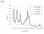
- Raman spectroscopy analysis Raman spectra were obtained under the same conditions as in Example 1. As shown in Fig. 12, the Raman spectrum had peaks at 198, 286, 453, 684, and 956 cm-1 , which suggests that the film has a lepidocrocite-type crystal structure. A peak was observed around 760 cm -1 , which indicated the presence of TMA cations and TMAH in the film.
- the Raman spectrum changed, indicating that the crystal structure had changed.
- the Raman shift had peaks at 153, 205, 395, 521, and 638 cm ⁇ 1 , suggesting that the crystal structure was anatase-type. From the above, it was estimated that the crystal structure transitioned from lepidocrocite-type to anatase-type when the laser intensity was 6.875 mW or more.
- the crystal structure is unstable in that it changes due to physical stimuli such as laser light or heat, and it is considered that the function that is expressed changes.
- MQ a O b (wherein M is at least one element selected from the group consisting of Groups 3, 4, 5, 6 and 7; Q is at least one element selected from the group consisting of Groups 12, 13, 14, 15, and 16 (excluding O); a is 0 to 2, b is greater than 0 and less than or equal to 2; 1.
- oxide materials disclosed herein can be used in a wide variety of applications, such as photocatalysis, dye decomposition, hydrogen production, batteries, supercapacitors, gas adsorbents, urea adsorbents, and ion conductors.
Landscapes
- Inorganic Compounds Of Heavy Metals (AREA)
Priority Applications (3)
| Application Number | Priority Date | Filing Date | Title |
|---|---|---|---|
| DE112024002537.4T DE112024002537T5 (de) | 2023-07-11 | 2024-07-11 | Oxidmaterial |
| CN202480045977.7A CN121464101A (zh) | 2023-07-11 | 2024-07-11 | 氧化物材料 |
| JP2025532820A JPWO2025013920A1 (https=) | 2023-07-11 | 2024-07-11 |
Applications Claiming Priority (2)
| Application Number | Priority Date | Filing Date | Title |
|---|---|---|---|
| US202363512971P | 2023-07-11 | 2023-07-11 | |
| US63/512,971 | 2023-07-11 |
Publications (1)
| Publication Number | Publication Date |
|---|---|
| WO2025013920A1 true WO2025013920A1 (ja) | 2025-01-16 |
Family
ID=94215901
Family Applications (1)
| Application Number | Title | Priority Date | Filing Date |
|---|---|---|---|
| PCT/JP2024/025126 Pending WO2025013920A1 (ja) | 2023-07-11 | 2024-07-11 | 酸化物材料 |
Country Status (4)
| Country | Link |
|---|---|
| JP (1) | JPWO2025013920A1 (https=) |
| CN (1) | CN121464101A (https=) |
| DE (1) | DE112024002537T5 (https=) |
| WO (1) | WO2025013920A1 (https=) |
Citations (5)
| Publication number | Priority date | Publication date | Assignee | Title |
|---|---|---|---|---|
| JP2008239368A (ja) * | 2007-03-26 | 2008-10-09 | Kao Corp | チタン酸ナノシート分散液 |
| WO2018079645A1 (ja) * | 2016-10-28 | 2018-05-03 | 神島化学工業株式会社 | 酸化物ナノシート及びその製造方法 |
| JP2020189775A (ja) * | 2019-05-24 | 2020-11-26 | 国立研究開発法人物質・材料研究機構 | ナノワイヤ構造体、その製造方法、イオン交換材料、光触媒材料、および、金属固定化材料 |
| WO2022174264A1 (en) * | 2021-02-11 | 2022-08-18 | Drexel University | Bottom-up, scalable synthesis of oxide-based sub-nano and nanofilaments and nanofilament-based two-dimensional flakes and mesoporous powders |
| WO2022261672A1 (en) * | 2021-06-10 | 2022-12-15 | Drexel University | Onium salt derived materials as chalcogen hosts |
-
2024
- 2024-07-11 JP JP2025532820A patent/JPWO2025013920A1/ja active Pending
- 2024-07-11 CN CN202480045977.7A patent/CN121464101A/zh active Pending
- 2024-07-11 DE DE112024002537.4T patent/DE112024002537T5/de active Pending
- 2024-07-11 WO PCT/JP2024/025126 patent/WO2025013920A1/ja active Pending
Patent Citations (5)
| Publication number | Priority date | Publication date | Assignee | Title |
|---|---|---|---|---|
| JP2008239368A (ja) * | 2007-03-26 | 2008-10-09 | Kao Corp | チタン酸ナノシート分散液 |
| WO2018079645A1 (ja) * | 2016-10-28 | 2018-05-03 | 神島化学工業株式会社 | 酸化物ナノシート及びその製造方法 |
| JP2020189775A (ja) * | 2019-05-24 | 2020-11-26 | 国立研究開発法人物質・材料研究機構 | ナノワイヤ構造体、その製造方法、イオン交換材料、光触媒材料、および、金属固定化材料 |
| WO2022174264A1 (en) * | 2021-02-11 | 2022-08-18 | Drexel University | Bottom-up, scalable synthesis of oxide-based sub-nano and nanofilaments and nanofilament-based two-dimensional flakes and mesoporous powders |
| WO2022261672A1 (en) * | 2021-06-10 | 2022-12-15 | Drexel University | Onium salt derived materials as chalcogen hosts |
Also Published As
| Publication number | Publication date |
|---|---|
| DE112024002537T5 (de) | 2026-04-09 |
| JPWO2025013920A1 (https=) | 2025-01-16 |
| CN121464101A (zh) | 2026-02-03 |
Similar Documents
| Publication | Publication Date | Title |
|---|---|---|
| Liu et al. | Unique physicochemical properties of two-dimensional light absorbers facilitating photocatalysis | |
| Damkale et al. | Highly crystalline anatase TiO 2 nanocuboids as an efficient photocatalyst for hydrogen generation | |
| Kondo et al. | Crystallization of mesoporous metal oxides | |
| Xu et al. | Self-generation of tiered surfactant superstructures for one-pot synthesis of Co3O4 nanocubes and their close-and non-close-packed organizations | |
| Ebina et al. | Synthesis and in situ X-ray diffraction characterization of two-dimensional perovskite-type oxide colloids with a controlled molecular thickness | |
| Li et al. | Titanate nanofiber reactivity: fabrication of MTiO3 (M= Ca, Sr, and Ba) perovskite oxides | |
| Lee et al. | Oriented attachment: An effective mechanism in the formation of anisotropic nanocrystals | |
| Ding et al. | Study on the anatase to rutile phase transformation and controlled synthesis of rutile nanocrystals with the assistance of ionic liquid | |
| Chong et al. | Enhanced photocatalytic activity of Ag3PO4 for oxygen evolution and Methylene blue degeneration: Effect of calcination temperature | |
| Gu et al. | Modified solvothermal strategy for straightforward synthesis of cubic NaNbO3 nanowires with enhanced photocatalytic H2 evolution | |
| Dong et al. | Single-crystalline mesoporous ZnO nanosheets prepared with a green antisolvent method exhibiting excellent photocatalytic efficiencies | |
| Liu et al. | Facile fabrication and mechanism of single-crystal sodium niobate photocatalyst: insight into the structure features influence on photocatalytic performance for H2 evolution | |
| Søndergaard et al. | In situ monitoring of TiO 2 (B)/anatase nanoparticle formation and application in Li-ion and Na-ion batteries | |
| Muruganandham et al. | Mineralizer-assisted shape-controlled synthesis, characterization, and photocatalytic evaluation of CdS microcrystals | |
| Niu et al. | Hydrothermal synthesis and formation mechanism of the anatase nanocrystals with co-exposed high-energy {001},{010} and [111]-facets for enhanced photocatalytic performance | |
| Hu et al. | Mesocrystalline nanocomposites of TiO2 polymorphs: Topochemical mesocrystal conversion, characterization, and photocatalytic response | |
| Wang et al. | MoS2@ MWCNTs with rich vacancy defects for effective piezocatalytic degradation of norfloxacin via innergenerated-H2O2: enhanced nonradical pathway and synergistic mechanism with radical pathway | |
| JP6578596B2 (ja) | 金属(x)ドープバナジン酸ビスマスの製造方法および金属(x)ドープバナジン酸ビスマス | |
| US9260316B2 (en) | Titanium dioxide nanoparticle, titanate, lithium titanate nanoparticle, and preparation methods thereof | |
| Tavakoli-Azar et al. | Synthesis and characterization of a perovskite nanocomposite of CdTiO3@ S with orthorhombic structure: investigation of photoluminescence properties and its photocatalytic performance for the degradation of congo red and crystal violet under sunlight | |
| Goswami et al. | Two‐dimensional MXenes: fundamentals, characteristics, synthesis methods, processing, compositions, structure, and applications | |
| JP2012140255A (ja) | 2dブロンズ型酸化タングステンナノシート、その製造方法およびそれを用いた光触媒とフォトクロミック素子 | |
| Ferreira et al. | One-dimensional nanostructures from layered manganese oxide | |
| Chang et al. | Effect of post-heat treatment on the photocatalytic activity of titanium dioxide nanowire membranes deposited on a Ti substrate | |
| Ma et al. | Mesoporous SrTiO 3 nanowires from a template-free hydrothermal process |
Legal Events
| Date | Code | Title | Description |
|---|---|---|---|
| 121 | Ep: the epo has been informed by wipo that ep was designated in this application |
Ref document number: 24839810 Country of ref document: EP Kind code of ref document: A1 |
|
| ENP | Entry into the national phase |
Ref document number: 2025532820 Country of ref document: JP Kind code of ref document: A |
|
| WWE | Wipo information: entry into national phase |
Ref document number: 2025532820 Country of ref document: JP |
|
| WWE | Wipo information: entry into national phase |
Ref document number: 112024002537 Country of ref document: DE |