WO2025013545A1 - 回転電機 - Google Patents
回転電機 Download PDFInfo
- Publication number
- WO2025013545A1 WO2025013545A1 PCT/JP2024/022163 JP2024022163W WO2025013545A1 WO 2025013545 A1 WO2025013545 A1 WO 2025013545A1 JP 2024022163 W JP2024022163 W JP 2024022163W WO 2025013545 A1 WO2025013545 A1 WO 2025013545A1
- Authority
- WO
- WIPO (PCT)
- Prior art keywords
- magnet
- slot
- electric machine
- rotating electric
- width
- Prior art date
- Legal status (The legal status is an assumption and is not a legal conclusion. Google has not performed a legal analysis and makes no representation as to the accuracy of the status listed.)
- Ceased
Links
Images




Classifications
-
- H—ELECTRICITY
- H02—GENERATION; CONVERSION OR DISTRIBUTION OF ELECTRIC POWER
- H02K—DYNAMO-ELECTRIC MACHINES
- H02K1/00—Details of the magnetic circuit
- H02K1/06—Details of the magnetic circuit characterised by the shape, form or construction
- H02K1/22—Rotating parts of the magnetic circuit
- H02K1/27—Rotor cores with permanent magnets
- H02K1/2706—Inner rotors
- H02K1/272—Inner rotors the magnetisation axis of the magnets being perpendicular to the rotor axis
- H02K1/274—Inner rotors the magnetisation axis of the magnets being perpendicular to the rotor axis the rotor consisting of two or more circumferentially positioned magnets
- H02K1/2753—Inner rotors the magnetisation axis of the magnets being perpendicular to the rotor axis the rotor consisting of two or more circumferentially positioned magnets the rotor consisting of magnets or groups of magnets arranged with alternating polarity
- H02K1/276—Magnets embedded in the magnetic core, e.g. interior permanent magnets [IPM]
Definitions
- the present invention relates to rotating electric machines that are installed in railway vehicles, automobiles, trucks, buses, construction machinery, etc.
- Patent Document 1 discloses a rotating electric machine in which a two-layer magnetic pole is formed by an outer magnet placed on the radially outer periphery and an inner magnet placed on the radially inner periphery.
- the rotating electric machine described in Patent Document 1 aims to increase reluctance torque in addition to magnet torque by utilizing the magnetizing effect of the core between the outer magnet and the inner magnet.
- a magnetic field in the opposite direction to the magnetization direction of a magnet is called a demagnetizing magnetic field, and when a demagnetizing magnetic field greater than the strength of magnetization (hereinafter referred to as the holding force) is applied, the magnet is demagnetized and loses its original magnetic force.
- the holding force and magnetization width of the magnet are designed to have sufficient resistance to such demagnetizing magnetic fields (hereinafter referred to as the demagnetization resistance).
- the sudden short circuit a sudden short circuit (hereinafter referred to as the sudden short circuit) occurs while the motor is running due to a decrease in insulation performance caused by aging of the motor windings, a broken electrical wiring, or a failure in the inverter circuit, the back electromotive force generated by the magnetic flux generates a short circuit current, which generates a massive demagnetizing magnetic field.
- the conventional two-layer structure it was difficult to ensure sufficient demagnetization resistance to such a demagnetizing magnetic field.
- the object of the present invention is to provide a highly reliable rotating electric machine that has sufficient demagnetization resistance even in the event of a sudden short circuit while maintaining high output and high efficiency.
- the present invention includes various embodiments, and one example thereof is a rotating electric machine including a cylindrical stator and a rotor concentrically arranged inside the stator with a gap therebetween, and when viewed in the axial direction of the rotating electric machine, the rotor has a plurality of magnetic poles arranged in a circumferential direction, and the magnetic poles have a first slot provided on the radially outer side and a second slot provided on the radially inner side, and the first slot and the second slot are each arranged symmetrically with respect to the magnetic pole center line, and the first Among the sides of the slot, the first opposing portion facing the second slot has three or more obtuse angle bend points, and among the sides of the second slot, the second opposing portion facing the first slot has the same number of obtuse angle bend points as the bend points of the first opposing portion or more, the first magnet inserted into the first slot and the second magnet inserted into the second slot are arranged so that the closer they are to the
- the present invention provides a highly reliable rotating electric machine that has sufficient demagnetization resistance even in the event of a sudden short circuit while maintaining high output and high efficiency.
- FIG. 1 is an explanatory diagram of the overall structure of a rotating electrical machine (motor) according to a first embodiment of the present invention.
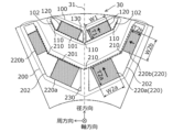
- FIG. 2 is an explanatory diagram of a magnetic pole structure in the first embodiment of the present invention.
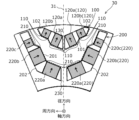
- FIG. 3A is an explanatory diagram of a magnetic pole structure in a second embodiment of the present invention.
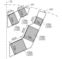
- FIG. 3B is an enlarged view of the magnet insertion holes 102, 202 of FIG. 3A, showing the dimensions of each magnet.
- FIG. 4 is an explanatory diagram of a modified example of the magnet configuration in the second embodiment of the present invention.
- FIG. 5 is an explanatory diagram of a magnetic pole structure in a comparative example of this embodiment.
- FIG. 6A is a voltage/current vector diagram when the motor is being driven.
- FIG. 6A is a voltage/current vector diagram when the motor is being driven.
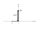
- FIG. 6B is a voltage/current vector diagram during a sudden short circuit.
- FIG. 7A is a diagram showing a magnetic pole structure in a comparative example of this embodiment, and shows a magnetic path when the magnetization direction widths of second magnet 220a and second magnet 220b are equal.
- FIG. 7B is a diagram showing a magnetic pole structure in a comparative example of this embodiment, and shows a magnetic path when the width in the magnetization direction of second magnet 220a is larger than the width in the magnetization direction of second magnet 220b.
- Figure 1 is an explanatory diagram of the overall structure of a rotating electric machine (motor) in the first embodiment of the present invention.
- Figure 2 is an explanatory diagram of the magnetic pole structure in the first embodiment of the present invention.
- the rotating electric machine 1 includes a cylindrical stator 10 and a rotor 20 that is concentrically arranged inside the stator 10 with a gap 21 between them.
- the direction parallel to the central axis of rotation of the rotor 20 of the rotating electric machine 1 is referred to as the "axial direction”
- the diameter direction of the rotor 20 perpendicular to the central axis of rotation of the rotor 20 of the rotating electric machine 1 is referred to as the "radial direction”
- the circumferential direction centered on the central axis of rotation of the rotor 20 of the rotating electric machine 1 is referred to as the "circumferential direction”.
- FIGS. 1 and 2 are views of the rotating electric machine 1 as viewed from the axial direction. Below, the shape, arrangement, size, etc. of each component when viewed from the axial direction of the rotating electric machine 1 will be described in detail.
- the rotor 20 has multiple magnetic poles 30 arranged in the circumferential direction.
- the magnetic pole 30 has a single first slot 100 provided on the radially outer periphery and a single second slot 200 provided on the radially inner periphery.
- the first slot 100 is a magnet slot into which a rectangular parallelepiped first magnet 120 is inserted.
- the second slot 200 is a magnet slot into which a rectangular parallelepiped second magnet 220 is inserted.
- the first slot 100 and the second slot 200 are each arranged symmetrically with respect to the magnetic pole center line (d-axis) 31.
- the pair of first magnets 120 inserted into the first slot 100 are arranged symmetrically with respect to the magnetic pole center line 31.
- the magnetic pole center line 31 is a line that extends radially from the central axis of rotation and passes through the center of the magnetic pole 30.
- the first slot 100 and the second slot 200 each have ribs 130, 230 at the position of the magnetic pole center line 31.
- the first slot 100 has a pair of magnet insertion holes (hereinafter, first magnet insertion holes) 102
- the second slot 200 has a pair of magnet insertion holes (hereinafter, second magnet insertion holes) 202.
- first magnet insertion holes hereinafter, first magnet insertion holes
- second magnet insertion holes One first magnet 120 is inserted into the first magnet insertion hole 102
- two second magnets 220 are inserted into the second magnet insertion hole 202.
- the pair of first magnet insertion holes 102 are arranged at a predetermined inclination angle with respect to the magnetic pole center line 31.
- the first slot 100 has a line-symmetric shape with the magnetic pole center line 31 as the axis of symmetry, and has a V-shape that opens radially outward.
- the pair of second magnet insertion holes 202 are arranged at a predetermined inclination angle with respect to the magnetic pole center line 31.
- the second slot 200 has a line-symmetric shape with the magnetic pole center line 31 as the axis of symmetry, and has a V-shape that opens radially outward.
- the ribs 130, 230 are provided for the purpose of avoiding deformation of the first slot 100 and the second slot 200 due to centrifugal load. Note that the ribs 130, 230 do not necessarily have to be provided in this position, and may be provided in another location inside the slot. Also, depending on the specifications of the rotating electric machine 1, the ribs 130, 230 may not be provided.
- the first slot 100 When viewed in the axial direction of the rotating electric machine 1, the first slot 100 has multiple sides. Among the multiple sides constituting the first slot 100, multiple sides (hereinafter also referred to as opposing sides) that face the second slot 200 form a first opposing portion 101 (see the dashed line in the figure).
- the first opposing portion 101 has three obtuse angle bending points 110. Note that the bending point 110 on the magnetic pole center line 31 corresponds to the lower end point of the first opposing portion 101 in the figure when the rib 130 is omitted. In other words, the bending point 110 on the magnetic pole center line 31 corresponds to the intersection of the left opposing side of the right first magnet insertion hole 102 and the right opposing side of the left first magnet insertion hole 102.
- the second slot 200 has multiple sides.
- multiple sides (hereinafter also referred to as opposing sides) opposing the first slot 100 form a second opposing portion 201 (see the dashed line in the figure).
- the second opposing portion 201 has the same number (three) of obtuse angle bending points 210 as the bending points 110 of the first opposing portion 101.
- the bending point 210 on the magnetic pole center line 31 corresponds to the illustrated lower end point of the second opposing portion 201 when the rib 230 is omitted.
- the bending point 210 on the magnetic pole center line 31 corresponds to the intersection of the left opposing side of the right second magnet insertion hole 202 and the right opposing side of the left second magnet insertion hole 202.
- the first magnet 120 inserted into the first slot 100 and the second magnet 220 inserted into the second slot 200 are both magnetized in the direction of the arrow ( ⁇ ), and the magnetic poles 30 form north poles.
- the magnetization directions of the first magnet 120 and the second magnet 220 are reversed for each magnetic pole aligned in the circumferential direction.
- the magnetic pole 30 adjacent to the magnetic pole 30 shown in Figure 2 forms a south pole.
- the pair of second magnets 220 positioned near the magnetic pole center line 31 is referred to as second magnets 220a
- second magnets 220b the pair of second magnets 220 positioned farther from the magnetic pole center line 31 than the second magnets 220a
- the angle between the second magnet 220b and the magnetic pole center line 31 is smaller than the angle between the second magnet 220a and the magnetic pole center line 31.
- the angle between the second magnet 220 and the magnetic pole center line 31 refers to the angle (the smaller angle) formed radially outward of the crossing angle between the direction perpendicular to the magnetization direction of the second magnet 220 and the magnetic pole center line 31.
- FIG. 5 is an explanatory diagram of the magnetic pole structure in a comparative example of this embodiment.
- the magnetic pole 30 in the comparative example has a two-layer structure with a first slot 100 provided on the radially outer side and a second slot 200 provided on the radially inner side.
- the first slot 100 has only two obtuse-angle bending points 110. Accordingly, the first magnet 120 is arranged perpendicular to the magnetic pole center line (d-axis) 31.
- the second slot 200 has three obtuse angle bending points 210.
- the second slot 200 has a pair of second magnets 220a arranged near the magnetic pole center line 31, and a pair of second magnets 220b arranged farther from the magnetic pole center line 31 than the second magnets 220a.
- the angle between the second magnets 220b and the magnetic pole center line 31 is smaller than the angle between the second magnets 220a and the magnetic pole center line 31.
- FIG. 6A is a voltage/current vector diagram when the motor is running
- Figure 6B is a voltage/current vector diagram when a sudden short circuit occurs. For simplicity, the voltage drop corresponding to the motor winding resistance has been omitted.
- the center line of the motor's magnetic poles is called the d-axis
- the axis that is 90° ahead of this in electrical angle is called the q-axis.
- the back electromotive force E0 generated by the magnet magnetic flux is generated on the q-axis, and the magnitude and phase of the voltage V applied to the motor are controlled so that it is balanced with the voltage drop ( ⁇ LI) caused by the magnetic flux generated by the motor current. In this state, the motor will not demagnetize.
- the spatial distribution of the demagnetization magnetic field in the gap 21 becomes sinusoidal with a peak on the d-axis (magnetic pole center line 31). Therefore, among the demagnetization magnetic fields 50A to 50D, the strongest demagnetization magnetic field is 50A, followed by 50B, 50C, and 50D in that order.
- the first magnet 120 and the second magnet 220a exposed to the severe demagnetization magnetic fields 50A and 50B near the magnetic pole center line 31, and the second magnet 220b exposed to the small demagnetization magnetic fields 50C and 50D away from the magnetic pole center line 31 are all configured with approximately the same magnetization direction width (thickness).
- the first magnet 120 is arranged perpendicular to the magnetic pole center line 31. In other words, the distance from the gap 21 to the first magnet 120 in the circumferential direction is approximately the same. For this reason, it is difficult to ensure sufficient demagnetization resistance against the strongest demagnetizing magnetic field 50A that occurs near the magnetic pole center line 31.
- the magnetic resistance of the magnet can be increased, and the amount of reverse magnetic flux entering the magnet due to the demagnetizing magnetic field can be reduced.
- the magnetization direction width (thickness) of the second magnet 220 is configured to become smaller the farther it is from the magnetic pole center line 31.
- the magnetization direction width T2a of the second magnet 220a arranged closer to the magnetic pole center line 31 and the magnetization direction width T2b of the second magnet 220b arranged farther from the magnetic pole center line 31 than the second magnet 220a are in the relationship T2a > T2b. This improves the magnetic resistance of the second magnet 220a, and therefore improves the demagnetization resistance even against the severe demagnetization magnetic fields 50A and 50B.
- the magnetization direction width T1 of the first magnet 120 and the smallest magnetization direction width T2b of the second magnet 220 may be configured to have a relationship of T1>T2b.
- the magnet width W1 in the direction perpendicular to the magnetization direction of the first magnet 120 and the magnet width W2b in the direction perpendicular to the magnetization direction of the magnet with the smallest magnetization direction width of the second magnet 220 may be configured to have a relationship of W1 ⁇ W2b.
- the magnetization direction widths T1, T2b and the magnet widths W1, W2b may be configured to have a relationship of T1>T2b and W1 ⁇ W2b. This can improve the magnetic resistance of the first magnet 120, and therefore the demagnetization resistance against the severe demagnetizing magnetic fields 50A and 50B can be improved.
- first opposing portion 101 of the first slot 100 has three obtuse angle bending points 110
- second opposing portion 201 of the second slot 200 also has three obtuse angle bending points 210.
- a space can be secured to make the magnetization direction width T2a of the second magnet 220a larger than the magnetization direction width T2b of the second magnet 220b.
- Figure 7A is a diagram showing the magnetic pole structure in a comparative example of this embodiment, and shows the magnetic path when the magnetization direction widths of the second magnet 220a and second magnet 220b are equal.
- Figure 7B is a diagram showing the magnetic pole structure in a comparative example of this embodiment, and shows the magnetic path when the magnetization direction width of the second magnet 220a is larger than the magnetization direction width of the second magnet 220b.
- FIG. 7A if the number of bending points 210 of the second opposing portion 201 of the second slot 200 is less than three (two in FIG. 7A), increasing the magnetization direction width of the second magnet 220a results in a configuration as shown in FIG. 7B.
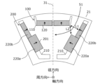
- a magnetic path width L2 smaller than the magnetic path width L1 secured as a path for the q-axis magnetic flux 51 is generated.
- the q-axis magnetic flux 51 required to generate reluctance torque is reduced, making it impossible to generate sufficient torque. Therefore, in the comparative example, the configuration as shown in FIG. 7B is not possible, and the configuration as shown in FIG. 7A is obtained, so that it is not possible to improve the demagnetization resistance by increasing the magnetization direction width of the second magnet 220a with respect to the strongest demagnetization magnetic field 50A generated near the magnetic pole center line 31.
- the first opposing portion 101 of the side of the first slot 100 that faces the second slot 200 has three obtuse angle bend points 110
- the second opposing portion 201 of the side of the second slot 200 that faces the first slot 100 has the same number of obtuse angle bend points 210 as the bend points 110 of the first opposing portion 101.
- the second magnet 220 is configured so that the magnetization direction width of the second magnet 220 decreases as the distance from the magnetic pole center line 31 increases. This makes it possible to provide a highly reliable rotating electric machine (motor) 1 that has sufficient demagnetization resistance even against sudden short circuits while maintaining high output and high efficiency.
- the magnet width W2a of the second magnet 220a may be smaller than the magnet width W2b of the second magnet 220b, thereby satisfying R2a>R2b.
- the relationship between the magnetization width T2a of the second magnet 220a and the magnetization width T2b of the second magnet 220b may be T2a ⁇ T2b.
- the magnet width W1 of the first magnet 120 can be made smaller than the magnet width W2b of the second magnet 220b to satisfy R1>R2b.
- the relationship between the magnetization direction width T1 of the first magnet 120 and the magnetization direction width T2b of the second magnet 220b may be T1 ⁇ T2b.
- Figure 3A is an explanatory diagram of the magnetic pole structure in the second embodiment of the present invention, and the difference from Figure 2 is the shape of the magnet insertion holes and the arrangement of the magnets.
- Figure 3B is an enlarged view of magnet insertion holes 102, 202 in Figure 3A, showing the dimensions of each magnet.
- the second slot 200 has a wider circumferential width than the first slot 100, and the position dependency of the demagnetization magnetic field is large. Therefore, in the first embodiment, as a method for improving the demagnetization resistance against the demagnetization magnetic fields 50A and 50B, an example was described in which the magnetization direction width of the second magnet 220 inserted into the second slot 200 is increased the closer it is to the magnetic pole center line 31, as shown in FIG. 2. In contrast, in the second embodiment, the magnetization direction width of not only the second magnet 220 but also the first magnet 120 inserted into the first slot 100 is increased the closer it is to the magnetic pole center line 31, thereby further improving the demagnetization resistance. The second embodiment will be described in detail below.
- the first magnet 120 inserted into the first slot 100 is configured so that the magnetization direction width of the first magnet 120 decreases as the distance from the magnetic pole center line 31 increases.
- the magnetization direction width T1a of the first magnet 120a arranged in a position closer to the magnetic pole center line 31 is configured to be larger than the magnetization direction width T1b of the first magnet 120b arranged in a position farther from the magnetic pole center line 31 than the first magnet 120a (T1a > T1b).
- the second magnet 220 inserted into the second slot 200 is configured so that the magnetization direction width of the second magnet 220 decreases as the distance from the magnetic pole center line 31 increases.
- three second magnets 220 are inserted into the second magnet insertion hole 202.
- the second magnets 220 are labeled a, b, and c in order of proximity to the magnetic pole center line 31.
- the magnetization direction width T2b of the second magnet 220b is configured to be larger than the magnetization direction width T2c of the second magnet 220c (T2b>T2c). Furthermore, the magnetization direction width T2a of the second magnet 220a is configured to be equal to or greater than the magnetization direction width T2b of the second magnet 220b (T2a>T2b). This improves the magnetic resistance of the first magnet 120a and the second magnets 220a, 220b, thereby improving the demagnetization resistance against the severe demagnetization magnetic fields 50A, 50B (see FIG. 5).
- first opposing portion 101 of the first slot 100 has seven obtuse-angled bending points 110.
- second opposing portion 201 of the second slot 200 has the same number (seven) of obtuse-angled bending points 210 as the bending points 110 of the first opposing portion. This allows space to be secured to make the magnetization direction width T1a of the first magnet 120a larger than the magnetization direction width T1b of the first magnet 120b. Similarly, space to make the magnetization direction widths of the second magnets 220c, 220b, and 220a larger in that order can be secured.
- the magnetization direction widths of the first magnet 120 and the second magnet 220 can be finely set according to the distance from the magnetic pole center line 31. This allows the demagnetization resistance to be improved without excess or deficiency.
- FIG. 4 is an explanatory diagram of a modified magnet configuration in the above-mentioned second embodiment.
- the shapes of the first slot 100 and the second slot 200 in this modified embodiment are the same as those in the second embodiment (see FIG. 3A).
- the first magnet 120 and the second magnet 220 are different from the second embodiment in that, as viewed in the axial direction of the rotating electric machine 1, the first magnet 120 and the second magnet 220 are each composed of two or more unit magnets 40 having a basic shape.
- the first magnet 120a is made up of three unit magnets 40 stacked in the magnetization direction.
- the first magnet 120b is made up of two unit magnets 40 stacked in the magnetization direction.
- the second magnet 220a is made up of three unit magnets 40 stacked in the magnetization direction, arranged in two rows in a direction perpendicular to the magnetization direction.
- the second magnet 220b is made up of three unit magnets 40 stacked in the magnetization direction, arranged in two rows in a direction perpendicular to the magnetization direction.
- the second magnet 220c is made up of two unit magnets 40 stacked in the magnetization direction.
- the magnet width in the direction perpendicular to the magnetization direction of the first magnets 120 and the second magnets 220 is determined by the number of unit magnets 40 inserted into the first slot 100 and the second slot 200.
- the dimensions of the unit magnets 40 are determined so that the number of unit magnets 40 included in the magnetic pole 30 is minimized.
- the dimensions of the unit magnets 40 are determined so that the number of unit magnets 40 included in the magnetic pole 30 is minimized, but the method of determining the dimensions of the unit magnets 40 is not limited to this.
- the magnetization direction width (thickness) of the unit magnets 40 may be halved, or the magnet width perpendicular to the magnetization direction of the unit magnets 40 may be halved, compared to the example shown in FIG. 4.
- the number of unit magnets 40 will be large, so as described above, it is preferable to determine the dimensions of the unit magnets 40 so that the number of unit magnets 40 included in the magnetic pole 30 is minimized.
- the shapes, sizes, and positional relationships of the unit magnets 40, the first magnet 120, and the second magnet 220 can be in various forms.
- the first magnet 120b and the second magnet 220c can each be composed of one unit magnet 40
- the first magnet 120a, the second magnet 220a, and the second magnet 220b can each be composed of two or more unit magnets 40.
- the first magnet 120 and the second magnet 220 can each be composed of one or more unit magnets 40 with a basic shape.
- the number of first magnets 120 and second magnets 220 constituting the magnetic pole 30 is not limited to the above-mentioned example.
- the number of bending points 110, 210 of the first opposing portion 101 and the second opposing portion 201 is also not limited to the above-mentioned example. It is sufficient that the first opposing portion 101 has at least three obtuse-angle bending points 110, and the second opposing portion 201 has the same number of obtuse-angle bending points 210 as the bending points 110 of the first opposing portion 101.
- stator 20 rotor 21: gap 30: magnetic pole 31: magnetic pole center line (d-axis)
- unit magnet 50 demagnetizing magnetic field 100: first slot 101: first opposing portion 102: first magnet insertion hole 110: obtuse angle bending point of first opposing portion 120: first magnet 130: rib of first slot 200: second slot 201: second opposing portion 202: second magnet insertion hole 210: obtuse angle bending point of second opposing portion 220: second magnet 230: rib of second slot
Landscapes
- Engineering & Computer Science (AREA)
- Power Engineering (AREA)
- Permanent Field Magnets Of Synchronous Machinery (AREA)
Abstract
回転電機は、ステータと、ステータの内側にギャップを介して同心配置されるロータと、を備え、回転電機の軸方向視において、ロータは、周方向に並ぶ複数の磁極を有し、磁極は、径方向外周側に設けられた第一スロットと、径方向内周側に設けられた第二スロットを有し、第一スロットの辺のうち、第二スロットと対向する第一対向部は、鈍角の屈曲点を3つ以上有するとともに、第二スロットの辺のうち、第一スロットと対向する第二対向部は、第一対向部の屈曲点と同数以上の鈍角の屈曲点を有し、第一スロットに挿入される第一磁石および第二スロットに挿入される第二磁石は、磁極中心線に近づくほどギャップからの距離が遠くなるように配置され、第二磁石は、磁極中心線からの距離が遠くなるほど第二磁石の磁化方向幅が小さくなる。
Description
本発明は鉄道車両、自動車、トラック、バス、建設機械などに搭載される回転電機に関わる。
モータ(回転電機)を小型・軽量にしながら、高出力・高効率化を図るため、トルクを増加可能な構造が考案されている。特許文献1には、径方向外周側に配置される外側磁石と径方向内周側に配置される内側磁石とによって、2層構造の磁極が形成された回転電機が開示されている。特許文献1に記載の回転電機では、外側磁石と内側磁石と間のコア部の磁化作用を活用することで、磁石トルクに加えてリラクタンストルクの増大を図っている。
磁石の磁化方向と反対向きの磁界を減磁磁界と呼び、磁化の強さ(以下、保持力)よりも大きな減磁磁界が印加されると、磁石は減磁して本来の磁力を失う。一般的なモータでは、このような減磁磁界に対しても十分な耐力(以下、減磁耐力)を有するように、磁石の保持力や磁化方向幅が設計されている。しかし、モータ駆動中において、モータ巻線の経年劣化等に伴う絶縁性能の低下や、電気配線の断線、インバータ回路の故障などが原因となり突発的な短絡(以下、突発短絡)が引き起こされると、磁石磁束が発生する逆起電力によって短絡電流が発生し、これが甚大な減磁磁界を発生する。従来の2層構造では、このような減磁磁界に対して十分な減磁耐力を確保することが困難であった。
本発明の目的は、高出力・高効率を維持しながら、突発短絡に対しても十分な減磁耐力を有する信頼性の高い回転電機を提供することにある。
上記目的を達成するために、本発明には様々な実施形態を含むが、その一例をあげると、本発明の回転電機は、円筒形のステータと、前記ステータの内側にギャップを介して同心配置されるロータと、を備えた回転電機であって、前記回転電機の軸方向視において、前記ロータは、周方向に並ぶ複数の磁極を有し、前記磁極は、径方向外周側に設けられた第一スロットと、径方向内周側に設けられた第二スロットを有し、前記第一スロットと前記第二スロットは、それぞれ磁極中心線に対して線対称に配置され、前記第一スロットの辺のうち、前記第二スロットと対向する第一対向部は、鈍角の屈曲点を3つ以上有するとともに、前記第二スロットの辺のうち、前記第一スロットと対向する第二対向部は、前記第一対向部の前記屈曲点と同数以上の鈍角の屈曲点を有し、前記第一スロットに挿入される第一磁石および前記第二スロットに挿入される第二磁石は、前記磁極中心線に近づくほど前記ギャップからの距離が遠くなるように配置され、前記第二磁石は、前記磁極中心線からの距離が遠くなるほど前記第二磁石の磁化方向幅が小さくなる。
本発明によれば、高出力・高効率を維持しながら、突発短絡に対しても十分な減磁耐力を有する信頼性の高い回転電機を提供できる。
上記した以外の課題、構成及び効果は、以下の実施形態の説明により明らかにされる。
以下、本発明の実施例について図面を参照して説明する。以下の説明では、同一の構成要素には同一の記号を付してある。それらの名称および機能は同じであり、重複説明は避ける。また、以下の説明では自動車、トラック、バスなど可変速駆動の永久磁石同期モータを対象としているが、本発明の効果はこれに限定されるものではなく、一定速を含む永久磁石同期機全般に適用可能である。
以下、図1乃至2を用いて、本発明の第1の実施例について説明する。図1は本発明の第1の実施例における回転電機(モータ)の全体構造の説明図である。図2は本発明の第1の実施例における磁極構造の説明図である。
図1に示すように、回転電機1は、円筒形のステータ10と、ステータ10の内側にギャップ21を介して同心配置されるロータ20とを備える。以下の説明では、回転電機1のロータ20の回転中心軸に平行な方向を「軸方向」と記し、回転電機1のロータ20の回転中心軸に直交するロータ20の直径方向を「径方向」と記し、回転電機1のロータ20の回転中心軸を中心とする円周方向を「周方向」と記す。図1および図2は、回転電機1を軸方向から見た図である。以下、回転電機1の軸方向視において、各構成の形状、配置、大きさ等について、詳しく説明する。図示するように、ロータ20は、周方向に並ぶ複数の磁極30を有する。
図2に示すように、磁極30は、径方向外周側に設けられた単一の第一スロット100と、径方向内周側に設けられた単一の第二スロット200を有する。第一スロット100は、直方体形状の第一磁石120が挿入される磁石スロットである。第二スロット200は、直方体形状の第二磁石220が挿入される磁石スロットである。第一スロット100と第二スロット200は、それぞれ磁極中心線(d軸)31に対して線対称に配置される。第一スロット100に挿入される一対の第一磁石120は、磁極中心線31に対して線対称に配置される。同様に、第二スロット200に挿入される二対の第二磁石220は、磁極中心線31に対して線対称に配置される。磁極中心線31は、回転中心軸から径方向に延在し、かつ、磁極30の中心を通過する線である。
本実施例において、第一スロット100と第二スロット200は、それぞれ磁極中心線31の位置にリブ130、230を有する。換言すれば、第一スロット100は、一対の磁石挿入孔(以下、第一磁石挿入孔)102を有し、第二スロット200は、一対の磁石挿入孔(以下、第二磁石挿入孔)202を有する。第一磁石挿入孔102には、一つの第一磁石120が挿入され、第二磁石挿入孔202には、二つの第二磁石220が挿入されている。一対の第一磁石挿入孔102は、磁極中心線31に対して所定の傾斜角度だけ傾いて配置されている。第一スロット100は、磁極中心線31を対称軸とする線対称形状であり、径方向外側に向かって開いたV字状を呈する。同様に、一対の第二磁石挿入孔202は、磁極中心線31に対して所定の傾斜角度だけ傾いて配置されている。第二スロット200は、磁極中心線31を対称軸とする線対称形状であり、径方向外側に向かって開いたV字状を呈する。
リブ130、230は、遠心荷重による第一スロット100と第二スロット200の変形を回避する目的で設けられる。なお、リブ130、230は、必ずしもこの位置に設ける必要は無く、スロット内部の別の場所に設けてもよい。また、回転電機1の仕様によっては、リブ130、230を設けなくてもよい。
回転電機1の軸方向視において、第一スロット100は、複数の辺を有している。第一スロット100を構成する複数の辺のうち、第二スロット200と対向する複数の辺(以下、対向辺とも記す)によって第一対向部101(図中、破線部参照)が形成される。第一対向部101は、鈍角の屈曲点110を3つ有する。なお、磁極中心線31上の屈曲点110は、リブ130を省略した場合の第一対向部101の図示下側の端点に相当する。換言すれば、磁極中心線31上の屈曲点110は、右側の第一磁石挿入孔102の左側の対向辺と、左側の第一磁石挿入孔102の右側の対向辺との交差点に相当する。
同様に、回転電機1の軸方向視において、第二スロット200は、複数の辺を有する。第二スロット200を構成する複数の辺のうち、第一スロット100と対向する複数の辺(以下、対向辺とも記す)によって第二対向部201(図中、破線部参照)が形成される。第二対向部201は、第一対向部101の屈曲点110と同数(3つ)の鈍角の屈曲点210を有する。なお、磁極中心線31上の屈曲点210は、リブ230を省略した場合の第二対向部201の図示下側の端点に相当する。換言すれば、磁極中心線31上の屈曲点210は、右側の第二磁石挿入孔202の左側の対向辺と、左側の第二磁石挿入孔202の右側の対向辺との交差点に相当する。
第一スロット100に挿入される第一磁石120と、第二スロット200に挿入される第二磁石220は、ともに矢印(→)の向きに磁化され、磁極30はN極を構成する。なお、第一磁石120と第二磁石220の磁化方向は、周方向に並ぶ磁極毎に反転している。つまり、図2に示す磁極30に隣接する磁極30はS極を構成する。
第二スロット200に挿入されている二対の第二磁石220のうち、磁極中心線31の近くに配置される一対の第二磁石220を第二磁石220aと記し、第二磁石220aよりも磁極中心線31から離れた位置に配置される一対の第二磁石220を第二磁石220bと記す。第二磁石220bと磁極中心線31との成す角度は、第二磁石220aと磁極中心線31との成す角度よりも小さい。なお、第二磁石220と磁極中心線31との成す角度とは、第二磁石220の磁化方向と直交する方向と、磁極中心線31との交差角のうち、径方向外側に形成される角度(小さい方の角度)のことを指す。
以下では本発明の実施形態に係る回転電機1の構造とすることにより得られる作用効果を、本実施形態の比較例との比較を通して説明する。
図5は本実施形態の比較例における磁極構造の説明図である。図5に示すように、比較例の磁極30は、径方向外周側に設けられた第一スロット100と、径方向内周側に設けられた第二スロット200を有する2層構造である。第一スロット100は、鈍角の屈曲点110を2つしか有していない。これに伴い、第一磁石120は磁極中心線(d軸)31に対して直交して配置される。
第二スロット200は、鈍角の屈曲点210を3つ有している。第二スロット200は、磁極中心線31の近くに配置される一対の第二磁石220aと、第二磁石220aよりも磁極中心線31から離れた位置に配置される一対の第二磁石220bとを有する。第二磁石220bと磁極中心線31との成す角度は、第二磁石220aと磁極中心線31との成す角度よりも小さい。
磁石の磁化方向と反対向きの磁界は、減磁磁界と呼ばれる。磁石の保持力よりも大きな減磁磁界が印加されると、磁石は減磁して本来の磁力を失う。一般的なモータでは、このような減磁磁界に対しても十分な減磁耐力を有するように、磁石の保持力や磁化方向幅が設計されている。図6Aはモータ駆動中における電圧・電流ベクトル図であり、図6Bは突発短絡時における電圧・電流ベクトル図である。簡単のため、モータ巻線抵抗に対応する電圧降下分の記載は省略している。一般に、モータの磁極中心線をd軸と呼び、これに対して電気角で90°進んだ軸をq軸と呼ぶ。
図6Aに示すように、磁石磁束が発生する逆起電力E0はq軸上に発生し、モータ電流が発生する磁束に起因した電圧降下分(ωLI)とバランスするように、モータの印加電圧Vの大きさと位相が制御される。このような状態であればモータが減磁することは無い。
しかしながら、モータ駆動中において、モータ巻線の経年劣化等に伴う絶縁性能の低下や、電気配線の断線、インバータ回路の故障などが原因となり突発短絡が引き起こされると、印加電圧Vがゼロになる。このため、図6Bに示すように逆起電力E0とバランスする電圧降下分(ωLI)を発生するように、負のd軸方向に短絡電流Iが発生し、これが甚大な減磁磁界を発生する。
このとき、図5に示すように、ギャップ21における減磁磁界の空間分布は、d軸(磁極中心線31)にピークを有する正弦波状になる。したがって、減磁磁界50A~50Dのうち、最も強い減磁磁界は50Aであり、50B、50C、50Dの順に弱くなる。比較例の構造では、磁極中心線31の近傍の甚大な減磁磁界50A、50Bにさらされる第一磁石120、第二磁石220aと、磁極中心線31から離れた小さな減磁磁界50C、50Dにさらされる第二磁石220bは、いずれも同程度の磁化方向幅(厚み)で構成されている。このため、突発短絡時に発生する減磁磁界に対して、十分な減磁耐力を確保することが困難である。また、第一磁石120は磁極中心線31に対して直交して配置されている。つまり、周方向において、ギャップ21から第一磁石120までの距離がほぼ同等になる。このため、磁極中心線31の近傍に発生する最も強い減磁磁界50Aに対して、十分な減磁耐力を確保することが困難である。
このように、磁極中心線31の近く配置される磁石ほど、強い減磁磁界にさらされる。ここで、磁石の厚みを厚くする、あるいは、磁石の磁化方向に直交する方向の幅を狭くすることにより、磁石の磁気抵抗を増加させ、減磁磁界により磁石に入ってくる逆向きの磁束の量を減らすことができる。
そこで本実施形態では図2に示すように、第二磁石220の磁化方向幅(厚み)を、磁極中心線31からの距離が遠くなるほど、小さくなるように構成する。すなわち、磁極中心線31に近い位置に配置される第二磁石220aの磁化方向幅T2aと、第二磁石220aよりも磁極中心線31から遠い位置に配置される第二磁石220bの磁化方向幅T2bとを、T2a>T2bの関係にする。これによって、第二磁石220aの磁気抵抗を向上できるので、甚大な減磁磁界50A、50Bに対しても減磁耐力を向上できる。
加えて、回転電機1の軸方向視において、第一磁石120の磁化方向幅T1と、第二磁石220のうち最も小さな磁化方向幅(すなわち、第二磁石220bの磁化方向幅)T2bとは、T1>T2bの関係を有する構成としてもよい。第一磁石120の厚みを第二磁石220bよりも厚くして第一磁石120の磁気抵抗をより高めることで、減磁磁界50A、50Bに対する減磁耐力をさらに向上することができる。また、回転電機1の軸方向視において、第一磁石120の磁化方向に対して直交方向の磁石幅W1と、第二磁石220のうち磁化方向幅が最も小さな磁石(すなわち、第二磁石220b)の磁化方向に対して直交方向の磁石幅W2bとが、W1<W2bの関係を有する構成としてもよい。第一磁石120の磁石幅W1を小さくして第一磁石120の磁気抵抗をより高めることで、減磁磁界50A、50Bに対する減磁耐力をさらに向上することができる。なお、磁化方向幅T1、T2b及び磁石幅W1、W2bは、T1>T2bかつW1<W2bの関係を有する構成としてもよい。これによって、第一磁石120の磁気抵抗を向上できるので、甚大な減磁磁界50A、50Bに対しても減磁耐力を向上できる。
さらに、第一スロット100の第一対向部101は鈍角の屈曲点110を3つ有し、第二スロット200の第二対向部201も鈍角の屈曲点210を3つ有している。これによって、第一磁石120および第二磁石220は、磁極中心線31に近づくほどギャップ21からの距離が遠くなるように配置できる。また、第二磁石220bの磁化方向幅T2bよりも、第二磁石220aの磁化方向幅T2aを大きくするためのスペースを確保できる。これにより、第二磁石220aの磁化方向幅(厚み)T2aを大きくして、減磁磁界50Aが通過する一層目及び二層目の磁石の全体の厚さ(T1+T2a)を十分に確保することができる。このため、磁極中心線31の近傍に発生する最も強い減磁磁界50Aに対して、第一磁石120、第二磁石220aの減磁耐力を向上できる。
図7Aおよび図7Bを用いて、仮に第二スロット200の第二対向部201の屈曲点210が3つ未満である場合に生じる問題点について説明する。図7Aは、本実施形態の比較例における磁極構造を示す図であって、第二磁石220aと第二磁石220bの磁化方向幅が等しい場合の磁路について示す。図7Bは、本実施形態の比較例における磁極構造を示す図であって、第二磁石220aの磁化方向幅が第二磁石220bの磁化方向幅よりも大きい場合の磁路について示す。
図7Aに示すように、仮に第二スロット200の第二対向部201の屈曲点210が3つ未満(図7Aでは2つ)の場合、第二磁石220aの磁化方向幅を大きくすると、図7Bに示すような構成となる。このような構成では、q軸磁束51の通路として確保していた磁路幅L1よりも小さな磁路幅L2が生じてしまう。すなわち、リラクタンストルクを発生するために必要なq軸磁束51が減少してしまうため、十分なトルクを発生できなくなる。したがって、比較例では、図7Bのような構成にはできず、図7Aの構成となるため、磁極中心線31の近傍に発生する最も強い減磁磁界50Aに対して、第二磁石220aの磁化方向幅を大きくすることによる減磁耐力の向上を図ることができない。
以上、第1の実施例では、第一スロット100の辺のうち、第二スロット200と対向する第一対向部101が、鈍角の屈曲点110を3つ有するとともに、第二スロット200の辺のうち、第一スロット100と対向する第二対向部201は、第一対向部101の屈曲点110と同数の鈍角の屈曲点210を有する。また、第二磁石220は、磁極中心線31からの距離が遠くなるほど第二磁石220の磁化方向幅が小さくなるように構成されている。これにより、高出力・高効率を維持しながら、突発短絡に対しても十分な減磁耐力を有する信頼性の高い回転電機(モータ)1を提供することができる。
なお、上記の構成の別の形態として、磁石の磁化方向幅Tと、磁化方向に対して直交方向の磁石幅Wの比(T/W)をアスペクト比Rと定義し、第二磁石220aのアスペクト比R2a(=T2a/W2a)を、第二磁石220bのアスペクト比R2b(=T2b/W2b)よりも大きくする構成としても良い。例えば、第二磁石220aの磁石幅W2aを第二磁石220bの磁石幅W2bよりも小さくすることにより、R2a>R2bを満足する構成とすることができる。この場合、第二磁石220aの磁化方向幅T2aと第二磁石220bの磁化方向幅T2bの関係は、T2a≦T2bであってもよい。加えて、第一磁石120のアスペクト比R1(=T1/W1)を、第二磁石220bのアスペクト比R2bよりも大きくする構成としても良い。例えば、第一磁石120の磁石幅W1を第二磁石220bの磁石幅W2bよりも小さくすることにより、R1>R2bを満足する構成とすることができる。この場合、第一磁石120の磁化方向幅T1と第二磁石220bの磁化方向幅T2bの関係は、T1≦T2bであってもよい。
図3A乃至3Bを用いて本発明の第2の実施例について説明する。図3Aは本発明の第2の実施例における磁極構造の説明図であり、図2との違いは磁石挿入孔の形状と磁石の配置である。図3Bは、図3Aの磁石挿入孔102、202の拡大図であり、各磁石の寸法を示す。
図5に示したように、第二スロット200の方が、第一スロット100よりも周方向に亘る幅が広く、減磁磁界の位置依存性が大きい。そこで、第1の実施例では、減磁磁界50A、50Bに対する減磁耐力を向上させる方法として、図2に示したように、磁極中心線31に近くなるほど、第二スロット200に挿入される第二磁石220の磁化方向幅を大きくする例について説明した。これに対して、第2の実施例では、第二磁石220だけでなく、磁極中心線31に近くなるほど、第一スロット100に挿入される第一磁石120の磁化方向幅を大きくすることで、さらなる減磁耐力の向上を図っている。以下、第2の実施例について、詳しく説明する。
図3Aおよび図3Bに示すように、回転電機1の軸方向視において、第一スロット100に挿入される第一磁石120は、磁極中心線31からの距離が遠くなるほど第一磁石120の磁化方向幅が小さくなるように構成されている。すなわち、磁極中心線31に近い位置に配置される第一磁石120aの磁化方向幅T1aは、第一磁石120aよりも磁極中心線31から遠い位置に配置される第一磁石120bの磁化方向幅T1bよりも大きくなるよう構成されている(T1a>T1b)。
また、第二スロット200に挿入される第二磁石220は、磁極中心線31からの距離が遠くなるほど第二磁石220の磁化方向幅が小さくなるように構成されている。図示する例では、第二磁石挿入孔202に3つの第二磁石220が挿入されている。以下、磁極中心線31に近い順に、第二磁石220に符号a、b、cをつけて記す。
第二磁石220bの磁化方向幅T2bは、第二磁石220cの磁化方向幅T2cよりも大きくなるよう構成されている(T2b>T2c)。さらに、第二磁石220aの磁化方向幅T2aは、第二磁石220bの磁化方向幅T2bと同等以上になるように構成されている(T2a≧T2b)。これによって、第一磁石120a、第二磁石220a、220bの磁気抵抗を向上できるので、甚大な減磁磁界50A、50B(図5参照)に対して減磁耐力を向上できる。
加えて、第一スロット100の第一対向部101は、鈍角の屈曲点110を7つ有する。同様に、第二スロット200の第二対向部201は、第一対向部の屈曲点110と同数(7つ)の鈍角の屈曲点210を有する。これによって、第一磁石120bの磁化方向幅T1bよりも、第一磁石120aの磁化方向幅T1aを大きくするためのスペースを確保できる。同様に、第二磁石220c、220b、220aの順に磁化方向幅を大きくするためのスペースを確保できる。さらに、第一スロット100の屈曲点110、および第二スロット200の屈曲点210の数を増やすことによって、第一磁石120および第二磁石220の磁化方向幅を、磁極中心線31からの距離に応じて木目細かく設定できる。このため、過不足なく減磁耐力を向上できる。
なお、上記の構成の別の形態として、第二磁石220a、220b、220cのアスペクト比R2a(=T2a/W2a)、R2b(=T2b/W2b)、R2c(=T2c/W2c)の関係が、R2a≧R2b>R2cとなるように構成しても良い。加えて、第一磁石120a、120bと第二磁石220cのアスペクト比R1a(=T1a/W1a)、R1b(=T1b/W1b)、R2cの関係が、R1a>R1b≧R2cとなるように構成してもよい。
次のような変形例も本発明の範囲内であり、変形例に示す構成と上述の実施形態で説明した構成を組み合わせたり、上述の異なる実施形態で説明した構成同士を組み合わせたり、以下の異なる変形例で説明する構成同士を組み合わせることも可能である。
<変形例1>
ところで、磁化方向幅が異なる磁石を複数使用すると、磁石コストが増大する。そこで、例えば、図4に示すように基本となる直方体形状の単位磁石40を径方向および周方向に組み合わせて磁石を構成する。これにより、磁石コストの増大を回避できる。図4は、上述した第2の実施例における磁石構成の変形例の説明図である。本変形例の第一スロット100および第二スロット200の形状は、第2の実施例(図3A参照)と同じである。本変形例では、回転電機1の軸方向視において、第一磁石120と第二磁石220が、それぞれ基本となる形状を備えた2つ以上の単位磁石40からなる点が、第2の実施例と異なっている。
ところで、磁化方向幅が異なる磁石を複数使用すると、磁石コストが増大する。そこで、例えば、図4に示すように基本となる直方体形状の単位磁石40を径方向および周方向に組み合わせて磁石を構成する。これにより、磁石コストの増大を回避できる。図4は、上述した第2の実施例における磁石構成の変形例の説明図である。本変形例の第一スロット100および第二スロット200の形状は、第2の実施例(図3A参照)と同じである。本変形例では、回転電機1の軸方向視において、第一磁石120と第二磁石220が、それぞれ基本となる形状を備えた2つ以上の単位磁石40からなる点が、第2の実施例と異なっている。
本変形例では、第一磁石120aは、磁化方向に積層された3個の単位磁石40からなる。また、第一磁石120bは、磁化方向に積層された2個の単位磁石40からなる。第二磁石220aは、磁化方向に積層された3個の単位磁石40が、磁化方向と直交する方向に2列配置されてなる。同様に、第二磁石220bは、磁化方向に積層された3個の単位磁石40が、磁化方向と直交する方向に2列配置されてなる。第二磁石220cは、磁化方向に積層された2個の単位磁石40からなる。
第一磁石120aの磁化方向幅T1aは、単位磁石40の磁化方向幅(厚み)tの3倍に相当する寸法である(T1a=3×t)。第一磁石120bおよび第二磁石220cの磁化方向幅T1b、T2cは、単位磁石40の磁化方向幅(厚み)tの2倍に相当する寸法である(T1b=T2c=2×t)。第二磁石220a、220bの磁化方向幅T2a、T2bは、単位磁石40の磁化方向幅(厚み)の3倍に相当する寸法である(T2a=T2b=3×t)。このように、本変形例では、回転電機1の軸方向視において、第一磁石120と第二磁石220の磁化方向幅は、第一スロット100と第二スロット200に挿入される単位磁石40の個数によって決まる。
第二磁石220aおよび第二磁石220bの磁化方向に直交する方向の磁石幅W2a、W2bは単位磁石40の磁化方向に直交する方向の磁石幅wの2倍に相当する寸法である(W2a=W2b=2×w)。このように、本変形例では、回転電機1の軸方向視において、第一磁石120、第二磁石220の磁化方向に対して直交方向の磁石幅は、第一スロット100と第二スロット200に挿入される単位磁石40の個数によって決まる。
また、本変形例では、回転電機1の軸方向視において、単位磁石40の寸法(磁化方向幅および磁化方向に直交する磁石幅)は、磁極30に含まれる単位磁石40の個数が最小となるように決定される。
このような構成とすることで、使用する磁石を共通化しつつ、適正な部品点数および管理コストを維持することが可能となる。したがって、本変形例によれば、高出力・高効率を維持しながら、突発短絡に対しても十分な減磁耐力を有する信頼性の高い回転電機(モータ)1を低コストで提供できる。
なお、図4に示す例では、単位磁石40の寸法が、磁極30に含まれる単位磁石40の個数が最小となるように決定される例について説明したが、単位磁石40の寸法の決定方法はこれに限定されない。例えば、図4に示す例に対して、単位磁石40の磁化方向幅(厚み)を半分にしてもよいし、単位磁石40の磁化方向に直交する磁石幅を半分にしてもよい。しかしながら、この場合、単位磁石40の個数が多くなるため、上述したように、単位磁石40の寸法は、磁極30に含まれる単位磁石40の個数が最小となるように決定することが好ましい。
単位磁石40、第一磁石120、および第二磁石220の形状、大きさ、配置関係は、種々の態様とすることができる。図示しないが、例えば、第一磁石120bおよび第二磁石220cをそれぞれ1つの単位磁石40で構成し、第一磁石120a、第二磁石220a、および第二磁石220bをそれぞれ2つ以上の単位磁石40で構成してもよい。つまり、第一磁石120と第二磁石220は、それぞれ基本となる形状を備えた1つ以上の単位磁石40により構成することができる。
<変形例2>
磁極30を構成する第一磁石120および第二磁石220の個数は、上述した例とする場合に限定されない。また、第一対向部101および第二対向部201の屈曲点110、210の数も上述した例に限定されない。少なくとも、第一対向部101が鈍角の屈曲点110を3つ以上有し、第二対向部201が第一対向部101の屈曲点110と同数以上の鈍角の屈曲点210を有していればよい。
磁極30を構成する第一磁石120および第二磁石220の個数は、上述した例とする場合に限定されない。また、第一対向部101および第二対向部201の屈曲点110、210の数も上述した例に限定されない。少なくとも、第一対向部101が鈍角の屈曲点110を3つ以上有し、第二対向部201が第一対向部101の屈曲点110と同数以上の鈍角の屈曲点210を有していればよい。
以上、本発明の実施形態について説明したが、上記実施形態は本発明の適用例の一部を示したに過ぎず、本発明の技術的範囲を上記実施形態の具体的構成に限定する趣旨ではない。
1:回転電機
10:ステータ
20:ロータ
21:ギャップ
30:磁極
31:磁極中心線(d軸)
40:単位磁石
50:減磁磁界
100:第一スロット
101:第一対向部
102:第一磁石挿入孔
110:第一対向部の鈍角の屈曲点
120:第一磁石
130:第一スロットのリブ
200:第二スロット
201:第二対向部
202:第二磁石挿入孔
210:第二対向部の鈍角の屈曲点
220:第二磁石
230:第二スロットのリブ
10:ステータ
20:ロータ
21:ギャップ
30:磁極
31:磁極中心線(d軸)
40:単位磁石
50:減磁磁界
100:第一スロット
101:第一対向部
102:第一磁石挿入孔
110:第一対向部の鈍角の屈曲点
120:第一磁石
130:第一スロットのリブ
200:第二スロット
201:第二対向部
202:第二磁石挿入孔
210:第二対向部の鈍角の屈曲点
220:第二磁石
230:第二スロットのリブ
Claims (8)
- 円筒形のステータと、前記ステータの内側にギャップを介して同心配置されるロータと、を備えた回転電機であって、
前記回転電機の軸方向視において、
前記ロータは、周方向に並ぶ複数の磁極を有し、前記磁極は、径方向外周側に設けられた第一スロットと、径方向内周側に設けられた第二スロットを有し、前記第一スロットと前記第二スロットは、それぞれ磁極中心線に対して線対称に配置され、
前記第一スロットの辺のうち、前記第二スロットと対向する第一対向部は、鈍角の屈曲点を3つ以上有するとともに、前記第二スロットの辺のうち、前記第一スロットと対向する第二対向部は、前記第一対向部の前記屈曲点と同数以上の鈍角の屈曲点を有し、
前記第一スロットに挿入される第一磁石および前記第二スロットに挿入される第二磁石は、前記磁極中心線に近づくほど前記ギャップからの距離が遠くなるように配置され、
前記第二磁石は、前記磁極中心線からの距離が遠くなるほど前記第二磁石の磁化方向幅が小さくなること、を特徴とする回転電機。 - 前記回転電機の軸方向視において、前記第一磁石の磁化方向幅T1と、前記第二磁石の最も小さな磁化方向幅T2とが、T1>T2の関係を有すること、を特徴とする請求項1に記載の回転電機。
- 前記回転電機の軸方向視において、前記第一磁石の磁化方向に対して直交方向の磁石幅W1と、前記第二磁石のうち磁化方向幅が最も小さな磁石の磁化方向に対して直交方向の磁石幅W2とが、W1<W2の関係を有すること、を特徴とする請求項1に記載の回転電機。
- 前記回転電機の軸方向視において、前記第一磁石は、前記磁極中心線からの距離が遠くなるほど前記第一磁石の磁化方向幅が小さくなること、を特徴とする請求項1に記載の回転電機。
- 前記回転電機の軸方向視において、前記第一磁石と前記第二磁石は、それぞれ基本となる形状を備えた1つ以上の単位磁石からなること、を特徴とする請求項1に記載の回転電機。
- 前記回転電機の軸方向視において、前記第一磁石と前記第二磁石の磁化方向幅は、前記第一スロットと前記第二スロットに挿入される前記単位磁石の個数によって決まること、を特徴とする請求項5に記載の回転電機。
- 前記回転電機の軸方向視において、前記第一磁石、前記第二磁石の磁化方向に対して直交方向の磁石幅は、前記第一スロットと前記第二スロットに挿入される前記単位磁石の個数によって決まること、を特徴とする請求項5に記載の回転電機。
- 前記回転電機の軸方向視において、前記単位磁石の寸法は、前記磁極に含まれる前記単位磁石の個数が最小となるように決定されること、を特徴とする請求項5に記載の回転電機。
Applications Claiming Priority (2)
| Application Number | Priority Date | Filing Date | Title |
|---|---|---|---|
| JP2023114637A JP2025012080A (ja) | 2023-07-12 | 2023-07-12 | 回転電機 |
| JP2023-114637 | 2023-07-12 |
Publications (1)
| Publication Number | Publication Date |
|---|---|
| WO2025013545A1 true WO2025013545A1 (ja) | 2025-01-16 |
Family
ID=94215620
Family Applications (1)
| Application Number | Title | Priority Date | Filing Date |
|---|---|---|---|
| PCT/JP2024/022163 Ceased WO2025013545A1 (ja) | 2023-07-12 | 2024-06-19 | 回転電機 |
Country Status (2)
| Country | Link |
|---|---|
| JP (1) | JP2025012080A (ja) |
| WO (1) | WO2025013545A1 (ja) |
Citations (8)
| Publication number | Priority date | Publication date | Assignee | Title |
|---|---|---|---|---|
| JP2000228838A (ja) * | 1998-12-01 | 2000-08-15 | Toyota Motor Corp | 永久磁石モータ |
| JP2005354899A (ja) * | 2005-09-09 | 2005-12-22 | Mitsubishi Electric Corp | 永久磁石型モータ |
| JP2015006124A (ja) * | 2013-05-21 | 2015-01-08 | 株式会社東芝 | 回転電機 |
| WO2018210577A1 (en) * | 2017-05-16 | 2018-11-22 | Robert Bosch Gmbh | Rotor and synchronous reluctance motor |
| WO2020057847A1 (de) * | 2018-09-18 | 2020-03-26 | Robert Bosch Gmbh | Rotor mit eingebetteten magneten |
| CN112510870A (zh) * | 2020-11-12 | 2021-03-16 | 珠海格力电器股份有限公司 | 电机转子、电机 |
| JP2021097550A (ja) * | 2019-12-19 | 2021-06-24 | 株式会社明電舎 | 埋込磁石形回転子および回転電機 |
| JP2023098697A (ja) * | 2021-12-28 | 2023-07-10 | 愛知製鋼株式会社 | ロータ、及びモータ |
-
2023
- 2023-07-12 JP JP2023114637A patent/JP2025012080A/ja active Pending
-
2024
- 2024-06-19 WO PCT/JP2024/022163 patent/WO2025013545A1/ja not_active Ceased
Patent Citations (8)
| Publication number | Priority date | Publication date | Assignee | Title |
|---|---|---|---|---|
| JP2000228838A (ja) * | 1998-12-01 | 2000-08-15 | Toyota Motor Corp | 永久磁石モータ |
| JP2005354899A (ja) * | 2005-09-09 | 2005-12-22 | Mitsubishi Electric Corp | 永久磁石型モータ |
| JP2015006124A (ja) * | 2013-05-21 | 2015-01-08 | 株式会社東芝 | 回転電機 |
| WO2018210577A1 (en) * | 2017-05-16 | 2018-11-22 | Robert Bosch Gmbh | Rotor and synchronous reluctance motor |
| WO2020057847A1 (de) * | 2018-09-18 | 2020-03-26 | Robert Bosch Gmbh | Rotor mit eingebetteten magneten |
| JP2021097550A (ja) * | 2019-12-19 | 2021-06-24 | 株式会社明電舎 | 埋込磁石形回転子および回転電機 |
| CN112510870A (zh) * | 2020-11-12 | 2021-03-16 | 珠海格力电器股份有限公司 | 电机转子、电机 |
| JP2023098697A (ja) * | 2021-12-28 | 2023-07-10 | 愛知製鋼株式会社 | ロータ、及びモータ |
Also Published As
| Publication number | Publication date |
|---|---|
| JP2025012080A (ja) | 2025-01-24 |
Similar Documents
| Publication | Publication Date | Title |
|---|---|---|
| US6794784B2 (en) | Permanent magnet reluctance motor with embedded permanent magnet holes | |
| CN109565198B (zh) | 转子以及磁阻马达 | |
| KR101880377B1 (ko) | 영구 자석 매립형 회전 전기 기기 | |
| JP7293371B2 (ja) | 回転電機の回転子 | |
| EP0923186B1 (en) | Permanent magnet rotor type electric motor | |
| US20180254677A1 (en) | Permanent magnet motor | |
| KR101481882B1 (ko) | 회전 전기기계 | |
| JP7314789B2 (ja) | 埋込磁石形回転子および回転電機 | |
| EP1598920A2 (en) | Permanent magnet rotary electric motor | |
| JP7362788B2 (ja) | 回転電機の回転子 | |
| JP6048191B2 (ja) | マルチギャップ型回転電機 | |
| US11837919B2 (en) | Rotary electric machine | |
| JP2008136298A (ja) | 回転電機の回転子及び回転電機 | |
| US20230344316A1 (en) | Rotating electric machine | |
| JP7318138B1 (ja) | 回転子および回転電機 | |
| JP2025012080A (ja) | 回転電機 | |
| JP2022121978A (ja) | 回転電機 | |
| JP3555016B2 (ja) | 磁石を用いた回転電機及び電磁機器 | |
| JP2020182358A (ja) | 回転電機の回転子 | |
| WO2022176144A1 (ja) | 回転子および回転電機 | |
| JPH09327160A (ja) | 電動機 | |
| US20240405620A1 (en) | Rotor | |
| JP7520998B2 (ja) | 回転子 | |
| WO2023105701A1 (ja) | 回転電機の回転子 | |
| WO2025238391A1 (ja) | 回転電機 |
Legal Events
| Date | Code | Title | Description |
|---|---|---|---|
| 121 | Ep: the epo has been informed by wipo that ep was designated in this application |
Ref document number: 24839441 Country of ref document: EP Kind code of ref document: A1 |
|
| NENP | Non-entry into the national phase |
Ref country code: DE |