WO2025013418A1 - 圧入装置 - Google Patents
圧入装置 Download PDFInfo
- Publication number
- WO2025013418A1 WO2025013418A1 PCT/JP2024/018418 JP2024018418W WO2025013418A1 WO 2025013418 A1 WO2025013418 A1 WO 2025013418A1 JP 2024018418 W JP2024018418 W JP 2024018418W WO 2025013418 A1 WO2025013418 A1 WO 2025013418A1
- Authority
- WO
- WIPO (PCT)
- Prior art keywords
- press
- jig
- fitting
- axis
- cylinder
- Prior art date
- Legal status (The legal status is an assumption and is not a legal conclusion. Google has not performed a legal analysis and makes no representation as to the accuracy of the status listed.)
- Pending
Links
Images




Classifications
-
- B—PERFORMING OPERATIONS; TRANSPORTING
- B23—MACHINE TOOLS; METAL-WORKING NOT OTHERWISE PROVIDED FOR
- B23P—METAL-WORKING NOT OTHERWISE PROVIDED FOR; COMBINED OPERATIONS; UNIVERSAL MACHINE TOOLS
- B23P19/00—Machines for simply fitting together or separating metal parts or objects, or metal and non-metal parts, whether or not involving some deformation; Tools or devices therefor so far as not provided for in other classes
-
- B—PERFORMING OPERATIONS; TRANSPORTING
- B23—MACHINE TOOLS; METAL-WORKING NOT OTHERWISE PROVIDED FOR
- B23P—METAL-WORKING NOT OTHERWISE PROVIDED FOR; COMBINED OPERATIONS; UNIVERSAL MACHINE TOOLS
- B23P19/00—Machines for simply fitting together or separating metal parts or objects, or metal and non-metal parts, whether or not involving some deformation; Tools or devices therefor so far as not provided for in other classes
- B23P19/02—Machines for simply fitting together or separating metal parts or objects, or metal and non-metal parts, whether or not involving some deformation; Tools or devices therefor so far as not provided for in other classes for connecting objects by press fit or for detaching same
Definitions
- the present invention relates to a press-fitting device.
- a press-fitting device is used to press-fit a press-fitting part into a part to be pressed in.
- One such press-fitting device has a lower press-fitting jig arranged at the bottom of a C-shaped column, an upper press-fitting jig arranged at the top of the C-shaped column facing the lower press-fitting jig, and a servo press that displaces the upper press-fitting jig toward the lower press-fitting jig.
- Patent Document 1 discloses a press machine having a similar configuration to this type of press-fitting device.
- the gear part is supported by a lower press-in jig, and the bearing is supported by an upper press-in jig.
- the upper press-in jig is displaced toward the lower press-in jig by a servo press mechanism, and the bearing supported by the upper press-in jig is inserted onto the shaft portion of the gear part supported by the lower press-in jig, and the shaft portion is pressed into the bearing.
- the press-fitting jigs need to be replaced every time the type of press-fitting part they support is changed.
- the press-fitting device In order to replace the press-fitting jig, the press-fitting device must be stopped and the replacement must be performed manually by an operator. If the frequency of replacing the press-fitting jig increases, this may result in an increase in work costs and a decrease in production efficiency. Therefore, there is a demand to minimize the impact on operating costs and production efficiency even if the frequency of replacing press-fitting jigs increases.
- One aspect of the present invention is a jig unit including a pair of press-fitting jigs disposed opposite to each other on a first axis line and a guide rail that supports one of the pair of press-fitting jigs movably in the first axial direction; a table on which the jig unit is mounted and which is rotatable about a rotation axis parallel to the first axis; a press mechanism that moves a cylinder disposed on a second axis parallel to the rotation shaft back and forth along the second axis, a plurality of the jig units are mounted on the table at intervals in a circumferential direction around the rotation axis, When viewed from the rotation axis direction, the first axis of each of the jig units is located on a virtual circle centered on the rotation axis,
- the one press-fitting jig was a press-fitting device having a connecting portion that was connected to the cylinder.
- FIG. 1 is a diagram illustrating a press-fitting device.
- FIG. 2 is a diagram illustrating the press-fitting device.
- FIG. 3 is a diagram illustrating a press-fitting device.
- FIG. 4 is a diagram illustrating a press-fitting jig.
- FIG. 5 is a diagram illustrating a press-fitting jig.
- FIG. 6 is a diagram illustrating a locking arm provided on the slider.
- FIG. 7 is a diagram illustrating the lock mechanism.
- FIG. 8 is a diagram illustrating the lock mechanism.
- FIG. 9 is a diagram illustrating the lock mechanism.
- FIG. 10 is a diagram for explaining an example of use of the press-fitting device.
- FIG. 1 is a diagram for explaining the press-fitting device 1, and is a perspective view of the press-fitting device 1 seen from diagonally above.
- FIG. 2 is a diagram for explaining the press-fitting device 1, and is a side view of the press-fitting device 1 seen from the side.
- FIG. 3 is a diagram for explaining the press-fitting device 1, and is a plan view of the press-fitting device 1 seen from above.
- the column 8 supporting the cylinder 7 is shown by a virtual line
- the movement locus of the axis X2 of the column 8 when the table 6 is rotated around the rotation axis C is shown by a virtual circle Im1.
- the area where the press-fitting jig 22 is located is shown by a dashed line.
- the press-fitting device 1 has a table 6 on which the jig unit 2 is mounted, a cylinder 7, and a column 8 that supports the cylinder 7.
- the column 8 is a frame that supports the cylinder 7 movably in the direction of the axis X2.
- the column 8 has a support base 81 placed on the installation surface GD, a vertical frame portion 82 extending upward from the support base 81 in the direction of the vertical line VL, a lower frame portion 83 extending laterally from a lower portion of the vertical frame portion 82 toward the table 6 side, and an upper frame portion 84 extending laterally from an upper portion of the vertical frame portion 82 toward the table 6 side.
- the lower frame portion 83 and the upper frame portion 84 extend in the same direction, and the column 8 is generally C-shaped in side view.
- the lower frame portion 83 and the upper frame portion 84 are spaced apart in the direction of a vertical line VL based on the installation state of the press-fitting device 1.
- the cylinder 7 is supported by the upper frame portion 84 so as to be movable back and forth along an axis X2.
- the axis X2 is a straight line that is perpendicular to the installation surface GD and extends along the vertical line VL.
- a servo press mechanism 75 (press mechanism) is attached to the top of the upper frame portion 84. The servo press mechanism 75 causes the cylinder 7 to advance and retreat in the direction of the axis X2 (up and down in FIG. 2).
- a space is provided between the upper frame portion 84 and the lower frame portion 83 in the direction of the vertical line VL so that the jig unit 2 mounted on the table 6 can pass through.
- the table 6 is rotatably supported via bearings (not shown) on a base 61 installed on the installation surface GD.
- the table 6 has a substantially circular outer diameter when viewed from above (see FIG. 3).
- the table 6 rotates around a rotation axis C, which is the central axis of the table 6, by a drive mechanism (not shown) installed inside the base 61.
- the upper surface 6a of the table 6 is a flat surface perpendicular to the rotation axis C.
- the upper surface 6a is a flat surface that is aligned along the horizontal line HL and perpendicular to the axis X2 described above and an axis X1 described later.
- the jig unit 2 has a lower press-fitting jig 21 and an upper press-fitting jig 22.
- the press-fitting jig 21 and the press-fitting jig 22 are disposed opposite to each other on a common axis X1.
- the press-fitting jig 22 is supported by the guide rail 23 via a slider 24.
- the slider 24 is capable of moving in the vertical direction along the guide rail 23.
- the press-fitting jig 22 supported by the slider 24 is also capable of moving in the vertical direction along the guide rail 23.
- a plurality of jig units 2 are mounted on the table 6 at predetermined intervals in the circumferential direction about the rotation axis C.
- Each jig unit 2 is provided in a direction along a diameter line L of the table 6 with the guide rail 23 facing the rotation axis C.
- four jig units 2 are mounted on the table 6.
- the jig units 2 are provided in the circumferential direction around the rotation axis C at 90 degree intervals.
- the column 8 is provided in a direction along the diameter line L of the table 6 with the cylinder 7 facing the rotation axis C side.
- the arrangement of each jig unit 2 and the relative positional relationship between the table 6 and the column 8 are determined so that the axis X2 of the cylinder 7 and the axis X1 of each jig unit 2 are located on a common imaginary circle Im1.
- the jig unit 2 mounted on the table 6 passes between the lower frame portion 83 (see Figure 2) and the upper frame portion 84 (see Figure 2) of the column 8 in sequence.
- the jig unit 2 is positioned at a position where the axis X1 of the jig unit 2 coincides with the axis X2 of the cylinder 7, and then the cylinder 7 is moved downward toward the table 6, thereby displacing the upper press-fitting jig 22 in a direction approaching the lower press-fitting jig 21.
- FIG. 6 is a diagram for explaining the engagement arms 25A, 25B provided on the slider 24.
- Fig. 6 shows the engagement arms 25A, 25B and a cross section of the guide rail 23 taken along line AA in Fig. 4, as well as the cylinder 7 in imaginary lines.
- the press-fitting jig 21 is fixed to a support base 210 installed on the table 6.
- the press-fitting jig 21 has a center pin 211 to be inserted into the workpiece W1.
- the press-fitting jig 21 is installed with the center pin 211 facing upward.
- the center pin 211 is located on the axis X1 and extends linearly upward.
- a peripheral portion 21a surrounding the center pin 211 serves as a mounting surface for the workpiece W1 that is extrapolated onto the center pin 211.
- the center pin 211 is inserted into an axial hole (not shown) of the workpiece W1, and the workpiece W1 is arranged in a direction along the axis X1.
- the axis W1a to be press-fitted into the workpiece W2 is arranged facing upward on the axis X1.
- the press-fitting jig 22 is attached to a recess 24a that opens on the lower surface of the slider 24.
- the press-fitting jig 22 has a center pin 221 to be inserted into the workpiece W2.
- the press-fitting jig 22 is installed with the center pin 221 facing downward.
- the center pin 221 is located on the axis X1 and extends linearly downward.
- the press-fitting jig 22 is provided with support arms 222 surrounding the center pin 221. Three support arms 222 are provided at intervals in the circumferential direction around the axis X1 (see Fig. 1).
- the workpiece W2 inserted around the center pin 221 is supported by the press-fitting jig 22 as the claw portion 222a provided at the tip of the support arm 222 engages with the lower surface.
- the press-fitting jig 22 is displaced toward the lower press-fitting jig 21, the shaft portion W1a of the workpiece W1 supported by the press-fitting jig 21 is press-fit into the workpiece W2.
- the slider 24 supporting the press-fitting jig 22 has a pair of engagement arms 25A, 25B provided on an upper surface 24b of a plate-shaped base 240.
- the engagement arms 25A, 25B extend along the axis X1 in a direction away from the press-fitting jig 22.
- the pair of engagement arms 25A, 25B are coupling portions with the cylinder 7.
- the engagement arms 25A, 25B have wall portions 251, 251 and locking portions 252, 252.
- the wall portions 251, 251 are plate-shaped portions extending linearly upward from the upper surface 24b of the base portion 240. As shown in Fig. 6, the wall portions 251, 251 have a width W240 in the circumferential direction around the rotation axis C that matches with the base portion 240.
- the walls 251, 251 face each other at a distance W251 in the radial direction of the rotation axis C of the table 6.
- the distance W251 between the walls 251, 251 is set to be larger than the outer diameter R71 of the flange portion 71 (W251>R71) so that the flange portion 71 of the cylinder 7 can be inserted therein.
- the locking portions 252, 252 protrude from the opposing surfaces of the wall portions 251, 251 in a direction approaching each other (a direction approaching the axis X1).
- the tip surfaces 252a, 252b of the locking portions 252, 252 are arc-shaped along the imaginary circles Im2, Im3, respectively.
- the tip surfaces 252a, 252b face each other with a gap W252 in the radial direction of the rotation axis C.
- the gap W252 between the tip surfaces 252a, 252b is set to be larger than the outer diameter R70 of the shaft portion 70 (W252>R70) so that the shaft portion 70 of the cylinder 7 can be inserted.
- the gap W252 is smaller than the outer diameter R71 of the flange portion 71.
- the jig unit 2 approaches the column 8, and the axis 70 of the cylinder 7 is inserted between the pair of engagement arms 25A, 25B in the process of reaching a position where the axis X1 of the jig unit 2 is coaxial with the axis X2 of the cylinder 7 on the column 8 side.
- the flange 71 and the locking parts 252, 252 are arranged in an overlapping positional relationship when viewed from the axis X1 direction (see FIG. 6).
- the imaginary circles Im2 and Im3 are imaginary circles centered on the rotation axis C of the table 6.
- the imaginary circle Im2 has a larger diameter than the imaginary circle Im1 centered on the rotation axis C.
- the imaginary circle Im3 has a smaller diameter than the imaginary circle Im1 centered on the rotation axis C.
- the imaginary circle Im1 corresponds to the movement trajectory that the axis X2 of the cylinder 7 describes on the table 6 when the table 6 rotates around the rotation axis C.
- the base 240 of the slider 24 is oriented along the diameter line L of the table 6.
- the region of the base 240 closer to the rotation axis C (left side in FIG. 6 ) than the engaging arm 25B serves as an engaging portion 241 with the guide rail 23.
- the engaging portion 241 is provided with a notch 242 through which the guide portion 232 and the connecting portion 233 on the guide rail 23 side can be inserted.
- the lower end of the guide rail 23 is fixed to the upper surface 6a of the table 6 (see FIG. 5).
- the guide rail 23 has a plate-shaped base 231 parallel to an end 241a on the inner diameter side of the slider 24 (base 240).
- the base 231 and the guide portion 232 are provided parallel to each other with a gap therebetween in the radial direction of the rotation axis C.
- the base 231 is wider than the guide portion 232, and the base 231 and the guide portion 232 are connected at their central portions in the width direction (vertical direction in the figure) by a connecting portion 233.
- the engagement portion 241 on the slider 24 side engages between the guide portion 232 and the base portion 231, so that the slider 24 is able to move in the longitudinal direction (up and down direction) of the guide rail 23 while being restricted from moving in a direction away from the guide rail 23.
- FIG. 7 to 9 are diagrams illustrating the lock mechanism 9.
- FIG. 7 and 8 a main part of the lock mechanism 9 is shown in cross section. This cross section corresponds to the cross section taken along line BB in FIG.
- FIG. 7 shows a state in which the lock shaft 91 of the lock mechanism 9 is disposed at a position (restricting position) where the movement of the slider 24 (press-fitting jig 22) is restricted.
- FIG. 8 shows a state in which the lock shaft 91 of the lock mechanism 9 is disposed in a position (non-restricted position) that allows the slider 24 (press-fitting jig 22) to move.
- 9 shows a cross section of a main part of the lock mechanism 9.
- Fig. 9 corresponds to the cross section taken along line AA in Fig. 7.
- a stopper 90 is fixed to a back surface 231a of a base portion 231.
- the stopper 90 is a plate-like member that spans between the back surface 231a of the base portion 231 and one side 231b in the width direction of the base portion 231.
- the stopper 90 has a substantially L-shape.
- the stopper 90 is fixed to the guide rail 23 by a bolt (not shown).
- the stopper 90 has an extension region 901 that extends toward the engaging arm 25B side (the right side in the figure) through the side of the base 231.
- a tip 901a of the extension region 901 reaches the side of the guide portion 232.
- a cylindrical mounting portion 902 is provided on the upper surface of the extension region 901.
- the lock shaft 91 is a columnar member having a rectangular cross section. As shown in Fig. 6, the lock shaft 91 is provided on the side of the slider 24 and oriented along the diameter line L of the table 6.
- the lock shaft 91 has a length L91 that crosses the slider 24 from the side of the guide rail 23 in the radial direction of the rotation axis C (left-right direction in the figure).
- the lock shaft 91 is arranged to be movable back and forth in the direction of the diameter line L (left and right direction in FIG. 7 ) while being prevented from falling off the slider 24 by a holder member 26 attached to the slider 24 and a guide rail (not shown).
- the holder member 26 has a side plate 261 (see FIG. 6) that restricts the lateral movement of the lock shaft 91, and an under plate 262 (see FIG. 7) that supports the underside of the lock shaft 91.
- the side plate 261 is connected to the under plate 262 with bolts BL, BL.
- the under plate 262 is fixed to the underside of the slider 24 with a bolt (not shown).
- the holder member 26 is provided to hold the lock shaft 91 on the side of the slider 24 while allowing movement of the lock shaft 91 in the radial direction (the direction of the diameter line L) of the rotation axis C of the lock shaft 91 .
- the movable member 93 is an integral part having a connecting portion 932 connected to an output shaft 951 of the motor 95 and an engaging portion 931 that engages with the engaging piece 92 .
- the connecting portion 932 is a plate-like member provided in a direction perpendicular to the axis X95 of the motor 95.
- the engaging portion 931 is a plate-like member provided in a direction along the axis X95 of the motor 95.
- the engaging portion 931 extends from a lower portion of the connecting portion 932 in a direction away from the motor 95 (to the left in FIG. 7 ).
- the movable member 93 is supported by the column 8 so as to be movable back and forth in the direction of the axis X95 while the rotation of the motor 95 about the axis X95 is restricted.
- the motor 95 is fixed to a side surface of the column 8 via a bracket 94.
- the bracket 94 has a first plate 941 on which the motor 95 is placed, and a second plate 942 having an insertion hole 942a for an output shaft 951.
- An output shaft 951 of the motor 95 is rotatably supported in an insertion hole 942a of the second plate 942.
- a tip end side of the output shaft 951 is screwed into a screw hole 932a provided in the connecting portion 932 of the movable member 93.
- the movable member 93 is displaced in the direction of the axis X95 according to the rotation direction of the output shaft 951 of the motor 95.
- the output shaft 951 of the motor 95 is screwed into the connecting portion 932 of the movable member 93 to form a screw feed mechanism.
- a recess 933 that is an engaging portion with the engaging element 92 is opened on the lower surface of the engaging portion 931.
- the recess 933 has contact surfaces 933a, 933b on both sides of the engaged portion 921 in the direction of the axis X95.
- the contact surface 933b is located on the rotation axis C side (left side in the figure) as viewed from the engaged portion 921.
- the contact surface 933a is located on the opposite side of the rotation axis C as viewed from the engaged portion 921.
- the contact surfaces 933a and 933b are perpendicular to the direction of advance/retract movement of the lock shaft 91 (left/right direction in the figure: direction of axis X95).
- the recess 933 and the engaged portion 921 are arranged in a positional relationship where they overlap when viewed from the axis X1 direction (see FIG. 9). This allows the lock shaft 91 to be displaced in conjunction with the movement of the movable member 93 in the axis X95 direction.
- a corner P1 on the slider 24 side (upper side in the figure) of the contact surface 933a is located on a virtual circle Im4 centered on the rotation axis C.
- a corner P2 on the opposite side of the contact surface 933b from the slider 24 (lower side in the figure) is located on a virtual circle Im5 centered on the rotation axis C.
- the virtual circle Im5 has a larger diameter than the virtual circle Im2 described above, and the virtual circle Im4 has a larger diameter than the virtual circle Im5 (Im4>Im5>Im2).
- a distance Wx between the virtual circle Im4 and the virtual circle Im5 is larger than a diameter R921 of the engaged portion 921.
- the operation of the press-fitting device 1 will be described.
- the slider 24 approaches the cylinder 7 supported by the column 8 from the circumferential direction about the rotation axis C, as shown in FIG.
- the slider 24 supported by the guide rail 23 is disposed at a height position where the flange portion 71 can be inserted between the upper surface 24b and the locking portions 252, 252 by the stopper 90 of the guide rail 23 (see FIG. 7).
- the cylinder 7 is inserted from the circumferential direction into the space between the locking portions 252, 252 of the pair of engaging arms 25A, 25B and between the locking portions 252, 252 and the upper surface 24b of the slider 24.
- the flange portion 71 on the outer periphery of the cylinder 7 is inserted under the locking portions 252, 252 of the pair of engagement arms 25A, 25B.
- the slider 24 is suspended from the flange portion 71 of the cylinder 7.
- the slider 24 and the press-fitting jig 22 supported by the slider 24 move downward toward the press-fitting jig 21 along the guide rail 23.
- the pressing force acting on the press-fitting jig 22 from the cylinder 7 is used to press-fit the workpiece W1 supported by the press-fitting jig 21 and the workpiece W2 supported by the press-fitting jig 22 together.
- the cylinder 7 is moved upward to position the lock shaft 91 above the stopper 90 (see the upper diagram in FIG. 8).
- the motor 95 is driven to displace the movable member 93 in a direction away from the motor 95 (to the left in the drawing)
- the engaged portion 921 of the engaging element 92 is pushed by the contact surface 933a of the recess 933 and displaced toward the stopper 90 together with the lock shaft 91.
- the cylinder 7 is lowered to place the lock shaft 91 on the mounting portion 902 on the stopper 90 side. This restricts the slider 24 from moving downward.
- the cylinder 7 is slightly lowered to release the contact between the flange portion 71 and the locking portions 252, 252 of the engaging arms 25A, 25B, and then the table 6 is rotated.
- the jig unit 2 which has completed the press-fitting operation moves in a direction away from the column 8, and a new jig unit approaches the column 8.
- FIG. 10 is a diagram for explaining an example of use of the press-fitting device 1.
- four jig units 2 are mounted on the table 6.
- the jig unit 2A located directly below the column 8 performs the press-fitting operation of the workpieces W1 and W2 using the press-fitting jigs 21 and 22.
- the press-fitting is being performed by the jig unit 2A
- other operations can be performed by the other jig units 2B to 2D.
- the jig unit 2B located downstream as viewed from the column 8 can remove the workpiece set after the press-fitting is completed.
- the adjacent jig unit 2C can set the workpieces W1 and W2 in the press-fitting jig. Therefore, the pressing operation (task 1), the pressing part removal operation (task 2), and the pressing part setting operation (task 3) can be performed in parallel, which reduces the waiting time of worker M compared to a pressing device that uses a C-shaped column to support only a pair of pressing jigs. Moreover, since the above-mentioned tasks 2 and 3 are simple tasks, even if the worker M is replaced by a robot, the waiting time for the robot can be shortened. Also, only task 3 after the press-fitting task may be replaced by a robot.
- the press-fitting work can be performed continuously by attaching the same press-fitting jigs 21, 22 to each jig unit 2 (2A to 2D). This reduces waiting time, and is expected to improve the efficiency of the press-fitting work.
- press-fitting device 1 There are a wide variety of combinations of workpieces that can be pressed into using the press-fitting device 1. If there are, for example, four different combinations of workpieces to be pressed into (see FIG. 10), the press-fitting jigs 21 and 22 of each jig unit 2 (2A-2D) are set to press-fitting jigs corresponding to combinations 1 to 4, respectively, so that the press-fitting of all combinations can be performed using a single press-fitting device. This makes the press-fitting device 1 adaptable to the manufacture of a wide variety of products in small quantities.
- the press-fitting device 1 is a jig unit 2 including a pair of press-fitting jigs (a lower press-fitting jig 21 (one jig) and an upper press-fitting jig 22 (the other jig)) disposed opposite to each other on an axis X1 (a first axis), and a guide rail 23 that supports the press-fitting jig 22 so as to be movable in the direction of the axis X1; a table 6 on which the jig unit 2 is mounted and which is rotatable about a rotation axis C parallel to the axis line X1;
- the press mechanism 75 has a servo press mechanism 75 (press mechanism) that moves the cylinder 7 arranged on an axis X2 (second axis) parallel to the rotation axis C back and forth along the axis X2.
- a plurality of jig units 2 are mounted on the table 6 at intervals in the circumferential direction around the rotation axis C.
- the axis X1 of each of the jig units 2 is located on an imaginary circle Im1 centered on the rotation axis C (see FIG. 3).
- the press-fitting jig 22 has a connecting portion that is connected to the cylinder 7 .
- the operations of replacing the press-fit jigs 21 and 22, setting the workpiece in the press-fit jigs 21 and 22, and removing the workpiece from the press-fit jig 21 can be performed. These operations can be performed in parallel with the operation of pressing the workpiece in the jig unit 2 having the press-fit jig 22 engaged with the cylinder 7. This is expected to improve the work efficiency.
- the multiple jig units 2 have the same combination of workpieces W1 and W2 supported by a pair of press-fit jigs 21 and 22.
- the shaft portion W1a of the workpiece W1 supported by the press-fitting jig 21 is pressed into the workpiece W2 supported by the press-fitting jig 22, this press-fitting operation is performed by the jig unit 2 having the press-fitting jig 22 engaged with the cylinder 7.
- the other jig unit 2 is located in a position removed from the cylinder 7, and can perform the operation of setting the workpieces W1, W2 into the press-fitting jigs 21, 22 and the operation of removing the workpieces W1, W2 from the press-fitting jig 21.
- the operation of setting the workpiece on the press-fitting jig and the operation of removing the workpiece from the press-fitting jig can be performed in parallel with the operation of pressing the workpiece into the workpiece, so that the production efficiency of press-fitted parts can be improved.
- the work of setting the workpiece in the press-fitting jig and the work of removing the workpiece from the press-fitting jig are performed by a robot, these operations can be performed in parallel with the press-fitting operation.
- the robot will be in a standby state during the press-fitting operation, which reduces the operating efficiency of the robot.
- the work of setting the workpiece in the press-fitting jig and the work of removing the workpiece from the press-fitting jig can be performed in parallel with the work of pressing the workpiece into the workpiece. This shortens the waiting time of the robot and reduces the non-operating time of the robot.
- the multiple jig units 2 have different combinations of workpieces W1 and W2 supported by a pair of press-fit jigs 21 and 22.
- press-fitting operations cannot be performed not only during the operations of setting the workpieces on the press-fitting jig and removing the workpieces from the press-fitting jig, but also during the operation of replacing the press-fitting jig.
- the press-in operation can be performed in parallel with the press-in jig replacement operation, thereby preventing a decrease in production efficiency due to the replacement of the press-in jig. Furthermore, since multiple jig units 2 are mounted on the table 6, by setting different press-in jigs in advance according to the combination of workpieces corresponding to each jig unit 2, it is possible to use a press-in jig suitable for the combination of workpieces simply by rotating the table 6. Changing the press-in jig accompanying the rotation of the table 6 is less of a workload and can be completed in a shorter time than replacing the press-in jig, so it is expected that a decrease in production efficiency will be prevented.
- the press-in jig 22 can be brought closer to the cylinder 7 in the circumferential direction about the rotation axis C.
- the cylinder 7 is inserted between the locking portions 252, 252 of the pair of engaging arms 25A, 25B in the circumferential direction, and the flange portion 71 on the outer periphery of the cylinder 7 is inserted below the locking portions 252, 252 of the pair of engaging arms 25A, 25B.
- the press-fitting jig 22 is connected to the cylinder 7 with the locking portions 252, 252 of the pair of engagement arms 25A, 25B locked to the flange portion 71 on the outer periphery of the cylinder 7. Furthermore, when the table 6 is rotated, the cylinder 7 moves out from between the locking portions 252, 252 of the pair of engaging arms 25A, 25B, and the engagement between the flange portion 71 on the outer periphery of the cylinder 7 and the locking portions 252, 252 of the pair of engaging arms 25A, 25B is released. With the above-described configuration, by rotating the table 6 about the rotation axis C, the press-fitting jig 22 that engages with the cylinder 7 can be switched.
- the press-fitting jig 22 has a locking mechanism 9 that prevents the press-fitting jig 22 from moving in the direction of the axis X1 while the press-fitting jig 22 is not engaged with the cylinder 7.
- the rotation axis C is oriented along the vertical line VL.
- the press-fitting jig 22 is located above the press-fitting jig 21 in the direction of the vertical line VL.
- the lock mechanism 9 is A stopper 90 fixed to the guide rail 23; A lock shaft 91 that is attached to the press-fitting jig 22 and can move forward and backward in a direction in which the stopper 90 can be engaged with and disengaged from the stopper 90;
- the lock mechanism includes a drive unit (motor 95, output shaft 951, movable member 93) that is provided on a column 8 that supports the cylinder 7 and moves the lock shaft 91 back and forth in the engagement/disengagement direction.
- the lock shaft 91 has an engagement element 92 (engagement shaft) that extends upward along the axis X1.
- the drive unit has a movable member 93 that moves back and forth in the engagement/disengagement direction.
- the movable member 93 has a pair of contact surfaces 933a, 933b having a width in the circumferential direction around the rotation axis C.
- the pair of contact surfaces 933a, 933b are provided in the radial direction of the rotation axis C with a gap therebetween that allows the engagement piece 92 to be inserted therein.
- the engaging element 92 is inserted from the circumferential direction into the recess 933 between the pair of contact surfaces 933a, 933b during the process until the axis X1, which is the central axis of the press-fitting jig 22, reaches a position where it intersects with the axis X2, which is the central axis of the cylinder 7.
- the engaging element 92 on the lock shaft 91 side and the movable member 93 (engaging portion 931) on the drive unit side are arranged in an overlapping positional relationship when viewed from the rotation axis direction. Therefore, the lock shaft 91 can be displaced in conjunction with the displacement of the movable member 93 in the axis X95 direction by the drive unit.
- the lock shaft 91 is displaced between a position where it overlaps with the stopper 90 (restricted position) when viewed from the direction of the rotation axis C, and a position where it does not overlap with the stopper 90 (released position). Since it is only necessary to provide a drive unit in the column 8, it is possible to reduce manufacturing costs compared to the case where a drive unit is provided in each of the jig units 2.
- the pressing jig 22 can be returned to its initial position where movement can be restricted by the locking mechanism 9, and then the movement restriction by the locking mechanism 9 can be restored by operating the movable member 93 by the drive unit. This makes it possible to automate the press-fitting operation in the jig unit 2 that has reached the column 8, which is expected to improve work efficiency.
Landscapes
- Engineering & Computer Science (AREA)
- Mechanical Engineering (AREA)
- Automatic Assembly (AREA)
Abstract
【課題】圧入治具の交換頻度が増えても作業コストや生産効率への影響を抑える。 【解決手段】第1の軸線上で対向配置された一対の圧入治具、および前記一対の圧入治具のうちの一方を前記第1の軸線方向に移動可能に支持するガイドレールを備える治具ユニットと、前記治具ユニットが搭載されると共に、前記第1の軸線に平行な回動軸回りに回動可能なテーブルと、前記回動軸に平行な第2の軸線上に配置したシリンダを、前記第2の軸線に沿って進退移動させるプレス機構と、を有し、前記テーブルでは、前記治具ユニットが前記回動軸回りの周方向に間隔を開けて複数搭載されており、前記回動軸方向から見て、前記治具ユニット各々の前記第1の軸線が、前記回動軸を中心とする仮想円上に位置しており、前記一方の圧入治具は、前記シリンダに連結される連結部を有する、圧入装置。
Description
本発明は、圧入装置に関する。
圧入装置は、圧入部品の被圧入部品への圧入に用られる。この種の圧入装置として、C型のコラムの下部に配置した下側の圧入治具と、C型のコラムの上部で、下側の圧入治具に対向配置させた上側の圧入治具と、上側の圧入治具を下側の圧入治具に向けて変位させるサーボプレスと、を有するものがある
特許文献1には、この種の圧入装置と同様の構成を備えるプレス機が開示されている。
特許文献1には、この種の圧入装置と同様の構成を備えるプレス機が開示されている。
例えば、ギア部品の軸部(圧入部品)を、環状のベアリング(被圧入部品)に圧入する場合、下側の圧入治具に、ギア部品を支持させると共に、上側の圧入治具にベアリングを支持させる。そして、サーボプレス機構により、上側の圧入治具を下側の圧入治具に向けて変位させて、上側の圧入治具が支持するベアリングを、下側の圧入治具で支持されたギア部品の軸部に外挿して、軸部をベアリングに圧入する。
ここで、C型のコラムでは、一対の圧入治具(上側の圧入治具と下側の圧入治具)のみを支持する仕様であるため、支持する圧入部品の種類が変更されるたびに、圧入治具の交換が必要である。
圧入治具の交換は、圧入装置を停止させて、作業者が手作業で行う必要がある。圧入治具の交換頻度が増えると、作業コストの増加や、生産効率の低下を生じる可能性がある。
そこで、圧入治具の交換頻度が増えても、作業コストや生産効率への影響を抑えることが求められている。
圧入治具の交換は、圧入装置を停止させて、作業者が手作業で行う必要がある。圧入治具の交換頻度が増えると、作業コストの増加や、生産効率の低下を生じる可能性がある。
そこで、圧入治具の交換頻度が増えても、作業コストや生産効率への影響を抑えることが求められている。
本発明のある態様は、
第1の軸線上で対向配置された一対の圧入治具、および前記一対の圧入治具のうちの一方を前記第1の軸線方向に移動可能に支持するガイドレールを備える治具ユニットと、
前記治具ユニットが搭載されると共に、前記第1の軸線に平行な回動軸回りに回動可能なテーブルと、
前記回動軸に平行な第2の軸線上に配置したシリンダを、前記第2の軸線に沿って進退移動させるプレス機構と、を有し、
前記テーブルでは、前記治具ユニットが前記回動軸回りの周方向に間隔を開けて複数搭載されており、
前記回動軸方向から見て、前記治具ユニット各々の前記第1の軸線が、前記回動軸を中心とする仮想円上に位置しており、
前記一方の圧入治具は、前記シリンダに連結される連結部を有する構成の圧入装置とした。
第1の軸線上で対向配置された一対の圧入治具、および前記一対の圧入治具のうちの一方を前記第1の軸線方向に移動可能に支持するガイドレールを備える治具ユニットと、
前記治具ユニットが搭載されると共に、前記第1の軸線に平行な回動軸回りに回動可能なテーブルと、
前記回動軸に平行な第2の軸線上に配置したシリンダを、前記第2の軸線に沿って進退移動させるプレス機構と、を有し、
前記テーブルでは、前記治具ユニットが前記回動軸回りの周方向に間隔を開けて複数搭載されており、
前記回動軸方向から見て、前記治具ユニット各々の前記第1の軸線が、前記回動軸を中心とする仮想円上に位置しており、
前記一方の圧入治具は、前記シリンダに連結される連結部を有する構成の圧入装置とした。
本発明のある態様によれば、圧入治具の交換頻度が増えても、作業コストや生産効率への影響を抑えることができる。
以下、本発明の実施形態を説明する。
図1は、圧入装置1を説明する図であって、圧入装置1を斜め上方から見た斜視図である。図2は、圧入装置1を説明する図であって、圧入装置1の側方から見た側面図である。図3は、圧入装置1を説明する図であって、圧入装置1の上方から見た平面図である。なお、図3では、シリンダ7を支持するコラム8を仮想線で示すと共に、テーブル6を回動軸C回りに回動させたときに、コラム8の軸線X2が辿る移動軌跡を仮想円Im1で示している。さらに、スライダ24の紙面奥側に支持された圧入治具22の位置を判りやすくするために、圧入治具22が位置する領域を破線で示している。
図1は、圧入装置1を説明する図であって、圧入装置1を斜め上方から見た斜視図である。図2は、圧入装置1を説明する図であって、圧入装置1の側方から見た側面図である。図3は、圧入装置1を説明する図であって、圧入装置1の上方から見た平面図である。なお、図3では、シリンダ7を支持するコラム8を仮想線で示すと共に、テーブル6を回動軸C回りに回動させたときに、コラム8の軸線X2が辿る移動軌跡を仮想円Im1で示している。さらに、スライダ24の紙面奥側に支持された圧入治具22の位置を判りやすくするために、圧入治具22が位置する領域を破線で示している。
図1に示すように、圧入装置1は、治具ユニット2が搭載されたテーブル6と、シリンダ7と、シリンダ7を支持するコラム8と、を有する。
図2に示すように、コラム8は、シリンダ7を軸線X2方向に移動可能に支持するフレームである。コラム8は、設置面GDに載置される支持台81と、支持台81から鉛直線VL方向の上側に延びる縦フレーム部82と、縦フレーム部82の下部から、テーブル6側の側方に延びる下側フレーム部83と、縦フレーム部82の上部から、テーブル6側の側方に延びる上側フレーム部84と、を有する。
下側フレーム部83と上側フレーム部84は、同一方向に延びており、側面視においてコラム8は、略C形状を成している。下側フレーム部83と上側フレーム部84は、圧入装置1の設置状態を基準とした鉛直線VL方向で間隔をあけて設けられている。
下側フレーム部83と上側フレーム部84は、同一方向に延びており、側面視においてコラム8は、略C形状を成している。下側フレーム部83と上側フレーム部84は、圧入装置1の設置状態を基準とした鉛直線VL方向で間隔をあけて設けられている。
上側フレーム部84では、シリンダ7が、軸線X2方向に進退移動可能に支持されている。ここで、軸線X2は、設置面GDに直交すると共に、鉛直線VLに沿う直線である。
上側フレーム部84の上部には、サーボプレス機構75(プレス機構)が付設されている。シリンダ7は、サーボプレス機構75により軸線X2方向に進退移動(図2における上下移動)する。
上側フレーム部84の上部には、サーボプレス機構75(プレス機構)が付設されている。シリンダ7は、サーボプレス機構75により軸線X2方向に進退移動(図2における上下移動)する。
上側フレーム部84と下側フレーム部83との間には、テーブル6に搭載された治具ユニット2が通過可能となるように、鉛直線VL方向の空間が確保されている。
テーブル6は、設置面GDに設置された基台61に、ベアリング(図示せず)を介して、回動可能に支持されている。上面視においてテーブル6は、略円形の外径を有している(図3参照)。テーブル6は、基台61の内部に設置した図示しない駆動機構により、テーブル6の中心軸である回動軸C回りに回動する。
テーブル6の上面6aは、回動軸Cに直交する平坦面である。上面6aは、水平線HL方向に沿うと共に、前記した軸線X2と、後記する軸線X1とに直交する平坦面である。
テーブル6は、設置面GDに設置された基台61に、ベアリング(図示せず)を介して、回動可能に支持されている。上面視においてテーブル6は、略円形の外径を有している(図3参照)。テーブル6は、基台61の内部に設置した図示しない駆動機構により、テーブル6の中心軸である回動軸C回りに回動する。
テーブル6の上面6aは、回動軸Cに直交する平坦面である。上面6aは、水平線HL方向に沿うと共に、前記した軸線X2と、後記する軸線X1とに直交する平坦面である。
治具ユニット2は、下側の圧入治具21と、上側の圧入治具22と、を有する。圧入治具21と、圧入治具22は、それぞれ、共通の軸線X1上で対向配置されている。
圧入治具22は、スライダ24を介してガイドレール23で支持されている。スライダ24は、ガイドレール23に沿って上下方向に移動可能である。スライダ24で支持された圧入治具22もまた、ガイドレール23に沿って上下方向に移動可能である。
圧入治具22は、スライダ24を介してガイドレール23で支持されている。スライダ24は、ガイドレール23に沿って上下方向に移動可能である。スライダ24で支持された圧入治具22もまた、ガイドレール23に沿って上下方向に移動可能である。
図3に示すように、テーブル6では、回動軸C回りの周方向に、所定間隔で複数の治具ユニット2が搭載されている。各治具ユニット2は、ガイドレール23を回動軸C側に向けた状態で、テーブル6の直径線Lに沿う向きで設けられている。
本実施形態では、4つの治具ユニット2がテーブル6に搭載されている。治具ユニット2は、回動軸C回りの周方向に90度間隔で設けられている。
本実施形態では、4つの治具ユニット2がテーブル6に搭載されている。治具ユニット2は、回動軸C回りの周方向に90度間隔で設けられている。
前記したコラム8は、シリンダ7を回動軸C側に向けた状態で、テーブル6の直径線Lに沿う向きで設けられている。
本実施形態では、シリンダ7の軸線X2と、各治具ユニット2の軸線X1とが、共通の仮想円Im1上に位置するように、各治具ユニット2の配置と、テーブル6と、コラム8との相対的な位置関係が決定されている。
本実施形態では、シリンダ7の軸線X2と、各治具ユニット2の軸線X1とが、共通の仮想円Im1上に位置するように、各治具ユニット2の配置と、テーブル6と、コラム8との相対的な位置関係が決定されている。
テーブル6を回動軸C回りに回動させると、テーブル6に搭載された治具ユニット2は、コラム8の下側フレーム部83(図2参照)と上側フレーム部84(図2参照)との間を、順番に通過する。
圧入装置1では、治具ユニット2を、当該治具ユニット2の軸線X1がシリンダ7の軸線X2に一致する位置に配置した後、シリンダ7をテーブル6側の下方に移動させることで、上側の圧入治具22を、下側の圧入治具21に近づける方向に変位させるようになっている。
圧入装置1では、治具ユニット2を、当該治具ユニット2の軸線X1がシリンダ7の軸線X2に一致する位置に配置した後、シリンダ7をテーブル6側の下方に移動させることで、上側の圧入治具22を、下側の圧入治具21に近づける方向に変位させるようになっている。
図4および図5は、圧入治具を説明する図である。図4では、上側の圧入治具22と共に、圧入治具22を支持するスライダ24と、スライダ24を支持するガイドレール23を断面で示している。図5では、下側の圧入治具21と共に、圧入治具21を支持する支持台210周りを断面で示している。
図4および図5では、治具ユニット2で圧入作業が行われるワークの組み合わせとして、ベアリング(ワークW2)と、ベアリングに圧入される軸部を有するギア部品(ワークW1)の組み合わせを例示している。
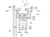
図6は、スライダ24が備える係合腕25A、25Bを説明する図である。図6は、図4におけるA-A線に沿って、係合腕25A、25Bと、ガイドレール23を切断した断面と共に、シリンダ7を仮想線で示している。
図4および図5では、治具ユニット2で圧入作業が行われるワークの組み合わせとして、ベアリング(ワークW2)と、ベアリングに圧入される軸部を有するギア部品(ワークW1)の組み合わせを例示している。
図6は、スライダ24が備える係合腕25A、25Bを説明する図である。図6は、図4におけるA-A線に沿って、係合腕25A、25Bと、ガイドレール23を切断した断面と共に、シリンダ7を仮想線で示している。
図5に示すように、圧入治具21は、テーブル6上に設置された支持台210に固定されている。圧入治具21は、ワークW1に挿入されるセンタピン211を有している。圧入治具21は、センタピン211を上方に向けて設置されている。センタピン211は、軸線X1上に位置しており、上方に向けて直線状に延びている。圧入治具21では、センタピン211を囲む周縁部21aが、センタピン211に外挿されたワークW1の載置面となっている。
圧入治具21では、センタピン211が、ワークW1が備える軸孔(図示せず)に挿入されて、ワークW1が軸線X1に沿う向きで配置される。この状態で、ワークW2に圧入される軸部W1aが、軸線X1上で上方を向いて配置される。
圧入治具21では、センタピン211が、ワークW1が備える軸孔(図示せず)に挿入されて、ワークW1が軸線X1に沿う向きで配置される。この状態で、ワークW2に圧入される軸部W1aが、軸線X1上で上方を向いて配置される。
図4に示すように、圧入治具22は、スライダ24の下面に開口する凹部24aに取り付けられている。圧入治具22は、ワークW2に挿入されるセンタピン221を有している。圧入治具22は、センタピン221を下方に向けて設置されている。センタピン221は、軸線X1上に位置しており、下方に向けて直線状に延びている。圧入治具22では、センタピン221を囲むように、支持腕222が設けられている。支持腕222は、軸線X1回りの周方向に間隔を開けて3つ設けられている(図1参照)。
圧入治具22では、センタピン221に外挿されたワークW2は、支持腕222が先端に備える爪部222aが下面に係止されることで、圧入治具22で支持される。
この状態で、圧入治具22を、下側の圧入治具21に向けて変位させると、圧入治具21で支持されたワークW1の軸部W1aが、ワークW2に圧入される。
圧入治具22では、センタピン221に外挿されたワークW2は、支持腕222が先端に備える爪部222aが下面に係止されることで、圧入治具22で支持される。
この状態で、圧入治具22を、下側の圧入治具21に向けて変位させると、圧入治具21で支持されたワークW1の軸部W1aが、ワークW2に圧入される。
図4に示すように、圧入治具22を支持するスライダ24では、板状の基部240の上面24bに、一対の係合腕25A、25Bが設けられている。係合腕25A、25Bは、軸線X1に沿って、圧入治具22から離れる方向に延びている。一対の係合腕25A、25Bは、シリンダ7との連結部である。
係合腕25A、25Bは、壁部251、251と、係止部252、252と、を有する。壁部251、251は、基部240の上面24bから、上方に向けて直線状に延びる板状の部位である。図6に示すように、壁部251、251は、回動軸C回りの周方向に、基部240と整合する幅W240を有している。
図4および図6に示すように、壁部251、251は、テーブル6の回動軸Cの径方向で、間隔W251を空けて対向している。壁部251、251の間隔W251は、シリンダ7のフランジ部71を挿入可能とするために、フランジ部71の外径R71よりも大きい間隔に設定されている(W251>R71)。
係合腕25A、25Bは、壁部251、251と、係止部252、252と、を有する。壁部251、251は、基部240の上面24bから、上方に向けて直線状に延びる板状の部位である。図6に示すように、壁部251、251は、回動軸C回りの周方向に、基部240と整合する幅W240を有している。
図4および図6に示すように、壁部251、251は、テーブル6の回動軸Cの径方向で、間隔W251を空けて対向している。壁部251、251の間隔W251は、シリンダ7のフランジ部71を挿入可能とするために、フランジ部71の外径R71よりも大きい間隔に設定されている(W251>R71)。
係止部252、252は、壁部251、251における互いの対向面から、互いに近づく方向(軸線X1に近づく方向)に突出している。図6に示すように、係止部252、252の先端面252a、252bは、それぞれ、仮想円Im2、Im3に沿う円弧状を成している。先端面252a、252bは、回動軸Cの径方向に間隔W252を空けて、互いに対向している。先端面252a、252bの間隔W252は、シリンダ7の軸部70を挿入可能とするために、軸部70の外径R70よりも大きい間隔に設定されている(W252>R70)。さらに、間隔W252は、フランジ部71の外径R71よりも小さい。
そのため、テーブル6の回動軸C回りの回動により、治具ユニット2がコラム8に近づいて、治具ユニット2の軸線X1が、コラム8側のシリンダ7の軸線X2と同軸となる位置に到達するまでの過程で、シリンダ7の軸部70が、一対の係合腕25A、25Bの間に挿入されるようになっている。治具ユニット2の軸線X1がシリンダ7の軸線X2と同軸になると、軸線X1方向から見て、フランジ部71と係止部252、252とが重なる位置関係で配置される(図6参照)。これにより、スライダ24側の係止部252、252が、フランジ部71の上面に係止できる状態となる。よって、後記するロック機構9による移動規制が解消されると、シリンダ7の軸線X2方向の移動に連動して、スライダ24が軸線X1に沿って上下方向に変位可能となる。さらに、スライダ24で支持された圧入治具22もまた、上下方向に変位できるようになる。
ここで、仮想円Im2、Im3は、テーブル6の回動軸Cを中心とする仮想円である。仮想円Im2は、回動軸Cを中心とする仮想円Im1よりも大径である。仮想円Im3は、回動軸Cを中心とする仮想円Im1よりも小径である。仮想円Im1は、テーブル6が回動軸C回りに回動する際に、シリンダ7の軸線X2がテーブル6上に描く移動軌跡に相当する。
スライダ24の基部240は、テーブル6の直径線Lに沿う向きで設けられている。基部240は、係合腕25Bよりも回動軸C側(図6における左側)の領域が、ガイドレール23との係合部241となっている。上面視において係合部241には、ガイドレール23側のガイド部232と連結部233を挿通可能な切欠部242が設けられている。
ガイドレール23の下端は、テーブル6の上面6aに固定されている(図5参照)。図6に示すように、ガイドレール23は、スライダ24(基部240)の内径側の端部241aに平行な板状の基部231を有する。基部231と、ガイド部232は、回動軸Cの径方向に間隔を開けて互いに平行に設けられている。基部231は、ガイド部232よりも幅広であり、基部231とガイド部232は、幅方向(図中、上下方向)の中央部が、連結部233により連結されている。
ガイド部232と基部231との間に、スライダ24側の係合部241が係合することで、スライダ24は、ガイドレール23から離れる方向の移動が規制された状態で、ガイドレール23の長手方向(上下方向)に移動可能となっている。
ガイドレール23の下端は、テーブル6の上面6aに固定されている(図5参照)。図6に示すように、ガイドレール23は、スライダ24(基部240)の内径側の端部241aに平行な板状の基部231を有する。基部231と、ガイド部232は、回動軸Cの径方向に間隔を開けて互いに平行に設けられている。基部231は、ガイド部232よりも幅広であり、基部231とガイド部232は、幅方向(図中、上下方向)の中央部が、連結部233により連結されている。
ガイド部232と基部231との間に、スライダ24側の係合部241が係合することで、スライダ24は、ガイドレール23から離れる方向の移動が規制された状態で、ガイドレール23の長手方向(上下方向)に移動可能となっている。
図7から図9は、ロック機構9を説明する図である。
図7および図8では、ロック機構9の主要部が断面で示されている。この断面は、図3におけるB-B線に沿う断面に相当する。
図7では、ロック機構9のロックシャフト91が、スライダ24(圧入治具22)の移動を規制する位置(規制位置)に配置されている状態を示している。
図8では、ロック機構9のロックシャフト91が、スライダ24(圧入治具22)の移動を許容する位置(規制解消位置)に配置されている状態を示している。
図9では、ロック機構9の要部断面が示されている。図9は、図7におけるA-A線に沿う断面に相当する。
図7および図8では、ロック機構9の主要部が断面で示されている。この断面は、図3におけるB-B線に沿う断面に相当する。
図7では、ロック機構9のロックシャフト91が、スライダ24(圧入治具22)の移動を規制する位置(規制位置)に配置されている状態を示している。
図8では、ロック機構9のロックシャフト91が、スライダ24(圧入治具22)の移動を許容する位置(規制解消位置)に配置されている状態を示している。
図9では、ロック機構9の要部断面が示されている。図9は、図7におけるA-A線に沿う断面に相当する。
図6に示すように、ガイドレール23では、基部231の裏面231aに、ストッパ90が固定されている。ストッパ90は、基部231の裏面231aと、基部231の幅方向の一側231bとに跨がる板状部材である。上面視においてストッパ90は、略L字形状を成している。
ストッパ90は、図示しないボルトにより、ガイドレール23に固定されている。
ストッパ90は、基部231の側方を通って係合腕25B側(図中、右側)に延びる延出領域901を有する。延出領域901の先端901aは、ガイド部232の側方に達している。図7に示すように、延出領域901の上面には、円柱状の載置部902が設けられている。
ストッパ90は、図示しないボルトにより、ガイドレール23に固定されている。
ストッパ90は、基部231の側方を通って係合腕25B側(図中、右側)に延びる延出領域901を有する。延出領域901の先端901aは、ガイド部232の側方に達している。図7に示すように、延出領域901の上面には、円柱状の載置部902が設けられている。
載置部902の上面902aには、ロックシャフト91の一方の端部910側が載置される。載置部902は、ロックシャフト91に直接接触する面積を抑えるために設けられている。
ロックシャフト91は、断面が四角形状を成す柱状の部材である。図6に示すように、ロックシャフト91は、スライダ24の側方で、テーブル6の直径線Lに沿う向きで設けられている。ロックシャフト91は、ガイドレール23の側方から、スライダ24を回動軸Cの径方向(図中、左右方向)に横断する長さL91を有している。
ロックシャフト91は、スライダ24に付設されたホルダ部材26と、図示しないガイドレールで、スライダ24からの脱落が規制された状態で、前記した直径線L方向(図7における左右方向)に進退移動可能に設けられている。
ロックシャフト91は、断面が四角形状を成す柱状の部材である。図6に示すように、ロックシャフト91は、スライダ24の側方で、テーブル6の直径線Lに沿う向きで設けられている。ロックシャフト91は、ガイドレール23の側方から、スライダ24を回動軸Cの径方向(図中、左右方向)に横断する長さL91を有している。
ロックシャフト91は、スライダ24に付設されたホルダ部材26と、図示しないガイドレールで、スライダ24からの脱落が規制された状態で、前記した直径線L方向(図7における左右方向)に進退移動可能に設けられている。
ホルダ部材26は、ロックシャフト91の側方への移動を規制するサイドプレート261(図6参照)と、ロックシャフト91の下面を支持するアンダプレート262(図7参照)と、を有する。サイドプレート261は、アンダプレート262にボルトBL、BLで連結されている。アンダプレート262は、スライダ24の下面に図示しないボルトで固定されている。
ホルダ部材26は、ロックシャフト91の回動軸Cの径方向(直径線L方向)への移動を許容しつつ、ロックシャフト91をスライダ24の側方で保持するために設けられている。
ホルダ部材26は、ロックシャフト91の回動軸Cの径方向(直径線L方向)への移動を許容しつつ、ロックシャフト91をスライダ24の側方で保持するために設けられている。
図7に示すように、ロックシャフト91の他方の端部911側には、上面91bに開口する有底穴915が設けられている。有底穴915には、係合子92の円柱状の基部920が挿入されている。
基部920の上端には、基部920よりも大径の被係合部921が設けられている。被係合部921は、可動部材93との係合部となっている。
基部920の上端には、基部920よりも大径の被係合部921が設けられている。被係合部921は、可動部材93との係合部となっている。
可動部材93は、モータ95の出力軸951に連結された連結部932と、係合子92に係合する係合部931とを有する一体部品である。
連結部932は、モータ95の軸線X95に直交する向きで設けられた板状部材である。係合部931は、モータ95の軸線X95に沿う向きで設けられた板状部材である。係合部931は、連結部932の下部からモータ95から離れる方向(図7における左方向)に延びている。
可動部材93は、モータ95の軸線X95回りの回転が規制された状態で、軸線X95方向に進退移動可能となるように、コラム8で支持されている。
連結部932は、モータ95の軸線X95に直交する向きで設けられた板状部材である。係合部931は、モータ95の軸線X95に沿う向きで設けられた板状部材である。係合部931は、連結部932の下部からモータ95から離れる方向(図7における左方向)に延びている。
可動部材93は、モータ95の軸線X95回りの回転が規制された状態で、軸線X95方向に進退移動可能となるように、コラム8で支持されている。
モータ95は、ブラケット94を介して、コラム8の側面に固定されている。ブラケット94は、モータ95が載置される第1プレート941と、出力軸951の挿通孔942aを持つ第2プレート942とを有する。
モータ95の出力軸951は、第2プレート942の挿通孔942aで回転可能に支持されている。出力軸951の先端側は、可動部材93の連結部932に設けたネジ孔932aに螺入されている。
出力軸951が連結部932に螺入することで、モータ95の出力軸951の回転方向に応じて、可動部材93が軸線X95方向に変位する。モータ95の出力軸951が、可動部材93の連結部932に螺入して、ネジ送り機構を構成している。
モータ95の出力軸951は、第2プレート942の挿通孔942aで回転可能に支持されている。出力軸951の先端側は、可動部材93の連結部932に設けたネジ孔932aに螺入されている。
出力軸951が連結部932に螺入することで、モータ95の出力軸951の回転方向に応じて、可動部材93が軸線X95方向に変位する。モータ95の出力軸951が、可動部材93の連結部932に螺入して、ネジ送り機構を構成している。
可動部材93では、前記した係合部931の下面に、係合子92との係合部である凹部933が開口している。凹部933は、軸線X95方向における被係合部921の両側に、接触面933a、933bを有する。
図9に示すように、接触面933bは、被係合部921から見て回動軸C側(図中、左側)に位置している。接触面933aは、被係合部921から見て回動軸Cとは反対側に位置している。接触面933a、933bは、ロックシャフト91の進退移動方向(図中、左右方向:軸線X95方向)に直交している。
そのため、可動部材93の軸線X95方向への変位に連動して、凹部933内に収容された係合子92の被係合部921が、凹部933の接触面933a、933bのうちの一方に押されて、軸線X95方向に変位するようになっている。
図9に示すように、接触面933bは、被係合部921から見て回動軸C側(図中、左側)に位置している。接触面933aは、被係合部921から見て回動軸Cとは反対側に位置している。接触面933a、933bは、ロックシャフト91の進退移動方向(図中、左右方向:軸線X95方向)に直交している。
そのため、可動部材93の軸線X95方向への変位に連動して、凹部933内に収容された係合子92の被係合部921が、凹部933の接触面933a、933bのうちの一方に押されて、軸線X95方向に変位するようになっている。
本実施形態では、モータ95側の可動部材93までが、コラム8に固定されている。ロックシャフト91が、スライダ24で支持されており、ストッパ90が、ガイドレール23に固定されている。
そのため、テーブル6の回動軸C回りの回動により、治具ユニット2がコラム8に近づいて、治具ユニット2の軸線X1が、コラム8側のシリンダ7の軸線X2と同軸となる位置に到達するまでの過程で、ロックシャフト91側の被係合部921が、可動部材93側の凹部933(接触面933a、933b)の間に挿入されるようになっている。治具ユニット2の軸線X1がシリンダ7の軸線X2と同軸になると、軸線X1方向から見て、凹部933と被係合部921とが重なる位置関係で配置される(図9参照)。これにより、可動部材93の軸線X95方向の移動に連動して、ロックシャフト91が変位できるようになる。
そのため、テーブル6の回動軸C回りの回動により、治具ユニット2がコラム8に近づいて、治具ユニット2の軸線X1が、コラム8側のシリンダ7の軸線X2と同軸となる位置に到達するまでの過程で、ロックシャフト91側の被係合部921が、可動部材93側の凹部933(接触面933a、933b)の間に挿入されるようになっている。治具ユニット2の軸線X1がシリンダ7の軸線X2と同軸になると、軸線X1方向から見て、凹部933と被係合部921とが重なる位置関係で配置される(図9参照)。これにより、可動部材93の軸線X95方向の移動に連動して、ロックシャフト91が変位できるようになる。
本実施形態では、凹部933への被係合部921の挿入を確実にするために、接触面933aのスライダ24側(図中、上側)の角部P1は、回動軸Cを中心とする仮想円Im4上に位置している。接触面933bのスライダ24とは反対側(図中、下側)の角部P2は、回動軸Cを中心とする仮想円Im5上に位置している。仮想円Im5は、前記した仮想円Im2よりも大径であり、仮想円Im4は、仮想円Im5よりも大径である(Im4>Im5>Im2)。仮想円Im4と仮想円Im5との間の間隔Wxは、被係合部921の直径R921よりも大きい。
これにより、テーブル6の回動により治具ユニット2が、コラム8に近づく過程で、係合子92側の被係合部921と、可動部材93側の凹部933とを確実に係合できる位置に配置できる。
これにより、テーブル6の回動により治具ユニット2が、コラム8に近づく過程で、係合子92側の被係合部921と、可動部材93側の凹部933とを確実に係合できる位置に配置できる。
ここで、圧入装置1の動作を説明する。
テーブル6の回動により、治具ユニット2がコラム8に近づくと、図6に示すように、スライダ24は、回動軸C回りの周方向から、コラム8に支持されたシリンダ7に近づくことになる。
ガイドレール23で支持されたスライダ24は、ガイドレール23が備えるストッパ90により、上面24bと係止部252、252との間に、フランジ部71を挿入可能な高さ位置に配置されている(図7参照)。そのため、圧入治具22の中心軸である軸線X1が、シリンダ7の中心軸である軸線X2と交差する位置に達するまでの過程で、シリンダ7が、一対の係合腕25A、25Bの係止部252、252の間と、係止部252、252と、スライダ24の上面24bとの間の空間に周方向から挿入される。
これにより、シリンダ7の外周のフランジ部71が、一対の係合腕25A、25Bの係止部252、252の下側に挿入される。
テーブル6の回動により、治具ユニット2がコラム8に近づくと、図6に示すように、スライダ24は、回動軸C回りの周方向から、コラム8に支持されたシリンダ7に近づくことになる。
ガイドレール23で支持されたスライダ24は、ガイドレール23が備えるストッパ90により、上面24bと係止部252、252との間に、フランジ部71を挿入可能な高さ位置に配置されている(図7参照)。そのため、圧入治具22の中心軸である軸線X1が、シリンダ7の中心軸である軸線X2と交差する位置に達するまでの過程で、シリンダ7が、一対の係合腕25A、25Bの係止部252、252の間と、係止部252、252と、スライダ24の上面24bとの間の空間に周方向から挿入される。
これにより、シリンダ7の外周のフランジ部71が、一対の係合腕25A、25Bの係止部252、252の下側に挿入される。
この状態で、モータ95を駆動して、可動部材93をモータ95側に変位させると、可動部材93側の凹部933に係合した係合子92の被係合部921は、凹部933の接触面933bにより押されて、ロックシャフト91と共に、モータ95側(図8における右側)に変位する。
そうすると、ロックシャフト91の端部910が、ストッパ90側の載置部902から外れた時点で、シリンダ7のフランジ部71の上面71aに、係合腕25A、25B側の係止部252、252の下面252c、252cが係止される。
これにより、スライダ24は、シリンダ7のフランジ部71に吊り下げられた状態となる。この状態でシリンダ7を下方に移動させると、スライダ24と、このスライダに支持された圧入治具22が、圧入治具21側の下方にガイドレール23に沿って移動する。
そうすると、ロックシャフト91の端部910が、ストッパ90側の載置部902から外れた時点で、シリンダ7のフランジ部71の上面71aに、係合腕25A、25B側の係止部252、252の下面252c、252cが係止される。
これにより、スライダ24は、シリンダ7のフランジ部71に吊り下げられた状態となる。この状態でシリンダ7を下方に移動させると、スライダ24と、このスライダに支持された圧入治具22が、圧入治具21側の下方にガイドレール23に沿って移動する。
最終的に、シリンダ7から圧入治具22に作用する押圧力により、圧入治具21に支持されたワークW1と、圧入治具22に支持されたワークW2との圧入作業が実施される。
圧入作業が終了すると、シリンダ7を上方に移動させて、ロックシャフト91をストッパ90よりも上側に配置する(図8における上側の図参照)。この状態で、モータ95を駆動して、可動部材93をモータ95から離れる方向(図中、左方向)に変位させると、係合子92の被係合部921は、凹部933の接触面933aにより押されて、ロックシャフト91と共に、ストッパ90側に変位する。
そして、ロックシャフト91がストッパ90側の載置部902上方に到達した時点で、シリンダ7を降下させて、ロックシャフト91をストッパ90側の載置部902に載置させる。これにより、スライダ24の下側への移動が規制される。
続いて、シリンダ7を僅かに降下させて、フランジ部71と、係合腕25A、25Bの係止部252、252との接触を解消させたのち、テーブル6を回動させる。
これにより、圧入作業を終了した治具ユニット2が、コラム8から離れる方向に移動すると共に、新たな治具ユニットがコラム8に近づくことになる。上記した操作を繰り返すことで、圧入作業が連続的に行われる。
圧入作業が終了すると、シリンダ7を上方に移動させて、ロックシャフト91をストッパ90よりも上側に配置する(図8における上側の図参照)。この状態で、モータ95を駆動して、可動部材93をモータ95から離れる方向(図中、左方向)に変位させると、係合子92の被係合部921は、凹部933の接触面933aにより押されて、ロックシャフト91と共に、ストッパ90側に変位する。
そして、ロックシャフト91がストッパ90側の載置部902上方に到達した時点で、シリンダ7を降下させて、ロックシャフト91をストッパ90側の載置部902に載置させる。これにより、スライダ24の下側への移動が規制される。
続いて、シリンダ7を僅かに降下させて、フランジ部71と、係合腕25A、25Bの係止部252、252との接触を解消させたのち、テーブル6を回動させる。
これにより、圧入作業を終了した治具ユニット2が、コラム8から離れる方向に移動すると共に、新たな治具ユニットがコラム8に近づくことになる。上記した操作を繰り返すことで、圧入作業が連続的に行われる。
図10は、圧入装置1の使用例を説明する図である。
前記したように、本実施形態では、テーブル6上に4つの治具ユニット2が搭載されている。図10に示すように、治具ユニット2のうち、コラム8の直下に位置する治具ユニット2Aでは、圧入治具21、22を用いたワークW1、W2の圧入作業が実施される。
治具ユニット2Aで圧入を実施している間、他の治具ユニット2B~2Dでは、他の作業を行うことができる。
例えば、テーブル6が、図中時計回り方向に回動する場合、コラム8から見て下流側に位置する治具ユニット2Bでは、圧入完了後のワーク組の取り出し作業を行える。その隣の治具ユニット2Cでは、ワークW1、W2の圧入治具へのセット作業を行える。
そのため、圧入作業(作業1)と、圧入部品の取り出し作業(作業2)と、圧入部品のセット作業(作業3)を、並行して行うことができるので、C型のコラムで一対の圧入治具のみを支持する仕様の圧入装置に比べて、作業者Mの待ち時間を短縮できる。
また、上記の作業2、作業3は、単純作業であり、作業者Mをロボットに置き換えた場合にも、ロボットの待ち時間を短縮できる。また、圧入作業後の作業3のみを、ロボットに置き換える構成としても良い。
前記したように、本実施形態では、テーブル6上に4つの治具ユニット2が搭載されている。図10に示すように、治具ユニット2のうち、コラム8の直下に位置する治具ユニット2Aでは、圧入治具21、22を用いたワークW1、W2の圧入作業が実施される。
治具ユニット2Aで圧入を実施している間、他の治具ユニット2B~2Dでは、他の作業を行うことができる。
例えば、テーブル6が、図中時計回り方向に回動する場合、コラム8から見て下流側に位置する治具ユニット2Bでは、圧入完了後のワーク組の取り出し作業を行える。その隣の治具ユニット2Cでは、ワークW1、W2の圧入治具へのセット作業を行える。
そのため、圧入作業(作業1)と、圧入部品の取り出し作業(作業2)と、圧入部品のセット作業(作業3)を、並行して行うことができるので、C型のコラムで一対の圧入治具のみを支持する仕様の圧入装置に比べて、作業者Mの待ち時間を短縮できる。
また、上記の作業2、作業3は、単純作業であり、作業者Mをロボットに置き換えた場合にも、ロボットの待ち時間を短縮できる。また、圧入作業後の作業3のみを、ロボットに置き換える構成としても良い。
圧入装置1で圧入作業を行うワークの組み合わせが、1種類のみである場合には、各治具ユニット2(2A~2D)に装着する圧入治具21、22を総て同じにすることで、圧入作業を連続して行うことができる。これにより、待ち時間を減らすことができるので、圧入作業の効率向上が期待できる。
圧入装置1で圧入作業を行うワークの組み合わせは多岐に亘る。圧入作業を行うワークの組み合わせが、例えば4種類である場合には(図10参照)、各治具ユニット2(2A~2D)の圧入治具21、22を、それぞれ、組合せ1から組合せ4に対応する圧入治具としておく、これにより、総ての組合せの圧入作業を、一台の圧入装置を用いて行うことができる。よって、少量多品種の製品製造に適応できる圧入装置1となる。
なお、圧入治具21、22の交換作業も、圧入作業に並行して行う場合には、例えば、図10における治具ユニット2Cで圧入治具21、22の交換作業を実施し、治具ユニット2DでワークW1、W2の圧入治具へのセット作業を行うことで、圧入作業を連続的に行うことができる。
以下、本発明のある態様における圧入装置1の構成を列挙する。
(1)圧入装置1は、
軸線X1(第1の軸線)上で対向配置された一対の圧入治具(下側の圧入治具21(一方の治具)、上側の圧入治具22(他方の治具))、および圧入治具22を軸線X1方向に移動可能に支持するガイドレール23を備える治具ユニット2と、
治具ユニット2が搭載されると共に、軸線X1に平行な回動軸C回りに回動可能なテーブル6と、
回動軸Cに平行な軸線X2(第2の軸線)上に配置したシリンダ7を、軸線X2に沿って進退移動させるサーボプレス機構75(プレス機構)と、を有する。
テーブル6では、治具ユニット2が回動軸C回りの周方向に間隔を開けて複数搭載されている。
回動軸C方向から見て、治具ユニット2各々の軸線X1が、回動軸Cを中心とする仮想円Im1上に位置している(図3参照)。
圧入治具22は、シリンダ7に連結される連結部を有する。
(1)圧入装置1は、
軸線X1(第1の軸線)上で対向配置された一対の圧入治具(下側の圧入治具21(一方の治具)、上側の圧入治具22(他方の治具))、および圧入治具22を軸線X1方向に移動可能に支持するガイドレール23を備える治具ユニット2と、
治具ユニット2が搭載されると共に、軸線X1に平行な回動軸C回りに回動可能なテーブル6と、
回動軸Cに平行な軸線X2(第2の軸線)上に配置したシリンダ7を、軸線X2に沿って進退移動させるサーボプレス機構75(プレス機構)と、を有する。
テーブル6では、治具ユニット2が回動軸C回りの周方向に間隔を開けて複数搭載されている。
回動軸C方向から見て、治具ユニット2各々の軸線X1が、回動軸Cを中心とする仮想円Im1上に位置している(図3参照)。
圧入治具22は、シリンダ7に連結される連結部を有する。
このように構成すると、テーブル6を回転させることで、シリンダ7に連結する圧入治具22を、各治具ユニット2に含まれる圧入治具22の間で切り替えることができる。
作業者が圧入治具21、22を直接交換する場合に比べて、圧入治具21、22の交換が容易になり、圧入治具21、22の交換に要する作業コストを低減できる。
また、シリンダ7に連結されていない圧入治具22を持つ治具ユニット2では、圧入治具21、22の交換作業、圧入治具21、22へのワークのセット作業、および圧入治具21からのワークの取り外し作業を行える。これらの作業は、シリンダ7に係合した圧入治具22を持つ治具ユニット2でのワークの圧入操作に並行して行える。これにより、作業効率の向上が期待できる。
作業者が圧入治具21、22を直接交換する場合に比べて、圧入治具21、22の交換が容易になり、圧入治具21、22の交換に要する作業コストを低減できる。
また、シリンダ7に連結されていない圧入治具22を持つ治具ユニット2では、圧入治具21、22の交換作業、圧入治具21、22へのワークのセット作業、および圧入治具21からのワークの取り外し作業を行える。これらの作業は、シリンダ7に係合した圧入治具22を持つ治具ユニット2でのワークの圧入操作に並行して行える。これにより、作業効率の向上が期待できる。
(2)複数の治具ユニット2は、一対の圧入治具21、22に支持させるワークW1、W2の組み合わせが同じ組み合わせである。
例えば、圧入治具21で支持したワークW1の軸部W1aを、圧入治具22で支持したワークW2に圧入する場合、この圧入作業は、シリンダ7に係合した圧入治具22を持つ治具ユニット2で行われる。他の治具ユニット2は、シリンダ7から外れた位置にあり、圧入治具21、22へのワークW1、W2のセット作業と、圧入治具21からのワークW1、W2の取り外し作業を行うことができる。
よって、上記のように構成すると、ワークへの圧入作業に並行して、圧入治具へのワークのセット作業と、圧入治具からのワークの取り外し作業を行える。
C型のコラムで一対の圧入治具のみを支持する仕様の圧入装置の場合、圧入治具へのワークのセット作業と、圧入治具からのワークの取り外し作業を行う間は、圧入作業を行うことができない。そのため、上記構成の圧入装置に比べると、圧入作業の実施間隔が空いてしまう。上記構成の圧入装置1では、ワークへの圧入作業に並行して、圧入治具へのワークのセット作業と、圧入治具からのワークの取り外し作業を行えるので、圧入部品の生産効率の向上とが期待できる。
よって、上記のように構成すると、ワークへの圧入作業に並行して、圧入治具へのワークのセット作業と、圧入治具からのワークの取り外し作業を行える。
C型のコラムで一対の圧入治具のみを支持する仕様の圧入装置の場合、圧入治具へのワークのセット作業と、圧入治具からのワークの取り外し作業を行う間は、圧入作業を行うことができない。そのため、上記構成の圧入装置に比べると、圧入作業の実施間隔が空いてしまう。上記構成の圧入装置1では、ワークへの圧入作業に並行して、圧入治具へのワークのセット作業と、圧入治具からのワークの取り外し作業を行えるので、圧入部品の生産効率の向上とが期待できる。
また、圧入治具へのワークのセット作業と、圧入治具からのワークの取り外し作業を、ロボットで行う場合には、圧入操作に並行してこれらの操作を行える。C型のコラムで一対の圧入治具のみを支持する仕様の圧入装置の場合、圧入作業の間、ロボットは待機状態になるので、ロボットの稼働効率が低くなる。これに対して、上記のように構成すると、ワークへの圧入作業に並行して、圧入治具へのワークのセット作業と、圧入治具からのワークの取り外し作業を行える。よって、ロボットの待ち時間を短くして、ロボットの非稼働時間を短くできる。
(3)複数の治具ユニット2は、一対の圧入治具21、22に支持させるワークW1、W2の組み合わせが異なる組み合わせである。
C型のコラムで一対の圧入治具のみを支持する仕様の圧入装置の場合、一対の圧入治具に支持させるワークの組み合わせが異なると、圧入治具へのワークのセット作業と、圧入治具からのワークの取り外し作業に加えて、圧入治具の交換作業の間も、圧入作業を行うことができない。
上記ように構成すると、圧入するワークの組み合わせが異なる場合でも、圧入作業に並行して、圧入治具の交換作業の間も行えるので、圧入治具の交換に伴う生産効率の低下を防ぐことができる。
さらに、複数の治具ユニット2がテーブル6に搭載されているので、治具ユニット2毎に対応するワークの組み合わせに応じて、異なる圧入治具をあらかじめセットしておくことで、テーブル6を回動させるだけで、ワークの組み合わせに適した圧入治具を使用できる。テーブル6の回動に伴う圧入治具の変更は、圧入治具の交換に比べて、作業負担が低く、かつより短時間で完了するので、生産効率の低下防止が期待できる。
上記ように構成すると、圧入するワークの組み合わせが異なる場合でも、圧入作業に並行して、圧入治具の交換作業の間も行えるので、圧入治具の交換に伴う生産効率の低下を防ぐことができる。
さらに、複数の治具ユニット2がテーブル6に搭載されているので、治具ユニット2毎に対応するワークの組み合わせに応じて、異なる圧入治具をあらかじめセットしておくことで、テーブル6を回動させるだけで、ワークの組み合わせに適した圧入治具を使用できる。テーブル6の回動に伴う圧入治具の変更は、圧入治具の交換に比べて、作業負担が低く、かつより短時間で完了するので、生産効率の低下防止が期待できる。
さらに、一対の圧入治具に支持させるワークの組み合わせが異なる組み合わせであっても、一台の圧入装置で対応できる。これにより、ワークの組み合わせの変更頻度が多い少量多品種生産に、容易に対応できる圧入装置を提供できる。
特に、C型のコラムで一対の圧入治具のみを支持する仕様の圧入装置の場合、ワークの組み合わせの変更頻度が多いときには、生産ライン上に複数の圧入装置を並列に設置するなどの対応が必要となる。さらに、圧入装置の使用が特定の生産ラインにのみ限定される。上記のように構成すると、圧入装置を複数台必要とせず、かつ特定の圧入部品の生産ラインにのみ使用が限定されない。上記の構成の圧入装置は、汎用性が高く、圧入部品が異なる他の生産ラインへの展開が可能となる。
また、C型のコラムで一対の圧入治具のみを支持する仕様の圧入装置の場合、圧入装置毎にロボットを用意する必要がある。これに対して、一台の圧入装置で、異なる組み合わせのワーク同士の圧入を行えるので、生産ラインにおける圧入装置の必要台数を抑えることができ、これにより付設するロボットの総数も抑えることができる。これにより、1設備にロボットを1台必要とする場合に比べてロボット負荷率の低減が可能になる。
特に、C型のコラムで一対の圧入治具のみを支持する仕様の圧入装置の場合、ワークの組み合わせの変更頻度が多いときには、生産ライン上に複数の圧入装置を並列に設置するなどの対応が必要となる。さらに、圧入装置の使用が特定の生産ラインにのみ限定される。上記のように構成すると、圧入装置を複数台必要とせず、かつ特定の圧入部品の生産ラインにのみ使用が限定されない。上記の構成の圧入装置は、汎用性が高く、圧入部品が異なる他の生産ラインへの展開が可能となる。
また、C型のコラムで一対の圧入治具のみを支持する仕様の圧入装置の場合、圧入装置毎にロボットを用意する必要がある。これに対して、一台の圧入装置で、異なる組み合わせのワーク同士の圧入を行えるので、生産ラインにおける圧入装置の必要台数を抑えることができ、これにより付設するロボットの総数も抑えることができる。これにより、1設備にロボットを1台必要とする場合に比べてロボット負荷率の低減が可能になる。
(4)圧入治具22の連結部は、圧入治具22を支持するスライダ24から、軸線X1に沿って圧入治具21から離れる方向に延びる一対の係合腕25A、25Bである。
一対の係合腕25A、25Bは、回動軸C回りの周方向に幅W240(図6参照)を持つ。
一対の係合腕25A、25Bの壁部251、251は、回動軸Cの径方向に、シリンダ7のフランジ部71が通過可能な間隔W251を開けて設けられている。
壁部251、251の互いの対向面には、互いに近づく方向に延びる係止部252、252が設けられている。
一対の係合腕25A、25Bの係止部252、252は、回動軸Cの径方向に、シリンダ7の軸部70が通過可能な間隔W252を開けて設けられている。
シリンダ7の軸部70の外周には、係止部252、252が上面71aに係止されるフランジ部71が設けられている。
一対の係合腕25A、25Bは、回動軸C回りの周方向に幅W240(図6参照)を持つ。
一対の係合腕25A、25Bの壁部251、251は、回動軸Cの径方向に、シリンダ7のフランジ部71が通過可能な間隔W251を開けて設けられている。
壁部251、251の互いの対向面には、互いに近づく方向に延びる係止部252、252が設けられている。
一対の係合腕25A、25Bの係止部252、252は、回動軸Cの径方向に、シリンダ7の軸部70が通過可能な間隔W252を開けて設けられている。
シリンダ7の軸部70の外周には、係止部252、252が上面71aに係止されるフランジ部71が設けられている。
テーブル6を回動軸C回りに回動させると、圧入治具22を、回動軸C回りの周方向からシリンダ7に近づけることができる。圧入治具22の中心軸である軸線X1が、シリンダ7の中心軸である軸線X2と交差する位置に達するまでの過程で、シリンダ7が、一対の係合腕25A、25Bの係止部252、252の間に周方向から挿入されて、シリンダ7の外周のフランジ部71が、一対の係合腕25A、25Bの係止部252、252の下側に挿入される。
これにより、圧入治具22は、一対の係合腕25A、25Bの係止部252、252を、シリンダ7の外周のフランジ部71に係止させた状態で、シリンダ7に連結される。
さらに、テーブル6を回動させると、シリンダ7が、一対の係合腕25A、25Bの係止部252、252の間から外れて、シリンダ7の外周のフランジ部71と、一対の係合腕25A、25Bの係止部252、252との係合が解消される。
上記のように構成すると、テーブル6を回動軸C回りに回動させることで、シリンダ7に係合する圧入治具22を切り替えることができる。
これにより、圧入治具22は、一対の係合腕25A、25Bの係止部252、252を、シリンダ7の外周のフランジ部71に係止させた状態で、シリンダ7に連結される。
さらに、テーブル6を回動させると、シリンダ7が、一対の係合腕25A、25Bの係止部252、252の間から外れて、シリンダ7の外周のフランジ部71と、一対の係合腕25A、25Bの係止部252、252との係合が解消される。
上記のように構成すると、テーブル6を回動軸C回りに回動させることで、シリンダ7に係合する圧入治具22を切り替えることができる。
(5)圧入治具22がシリンダ7に係合していない間、圧入治具22の軸線X1方向への移動を阻止するロック機構9を有する。
例えば、ロック機構9により、圧入治具22をシリンダ7との係合に適した高さ位置に保持できる。これにより、テーブル6の回転によるシリンダ7と係合する圧入治具22の切り替えを速やかに行うことができる。
また、シリンダ7と係合した後に、ロック機構9による移動阻止を解消することで、圧入治具22を、シリンダ7の変位に連動して上下方向に移動させることができる。
また、シリンダ7と係合した後に、ロック機構9による移動阻止を解消することで、圧入治具22を、シリンダ7の変位に連動して上下方向に移動させることができる。
(6)回動軸Cは、鉛直線VLに沿う向きで設けられている。
圧入治具22は、鉛直線VL方向において、圧入治具21よりも上側に位置する。
圧入治具22は、鉛直線VL方向において、圧入治具21よりも上側に位置する。
このように構成すると、ロック機構9による移動規制を解除すると、圧入治具22には、圧入治具21が位置する下側に向けた移動力を生じる重力が作用する。
サーボプレス機構75は、圧入作業を行う際に、圧入治具22が係合したシリンダ7を、圧入治具21が位置する下側に向けて移動させる。圧入治具22に作用する重力が、シリンダ7を下側に向けて移動させる際にサーボプレス機構75が必要とする駆動力を低減させる。例えば、サーボプレス機構75がサーボモータを備えるサーボプレス機構である場合には、サーボモータの負荷を低減できる。これにより、サーボモータの電力消費量の低減が期待できる。
サーボプレス機構75は、圧入作業を行う際に、圧入治具22が係合したシリンダ7を、圧入治具21が位置する下側に向けて移動させる。圧入治具22に作用する重力が、シリンダ7を下側に向けて移動させる際にサーボプレス機構75が必要とする駆動力を低減させる。例えば、サーボプレス機構75がサーボモータを備えるサーボプレス機構である場合には、サーボモータの負荷を低減できる。これにより、サーボモータの電力消費量の低減が期待できる。
(I)ロック機構9は、
ガイドレール23に固定されたストッパ90と、
圧入治具22側に取り付けられて、ストッパ90に対する係脱方向に進退移動可能なロックシャフト91と、
シリンダ7を支持するコラム8に設けられて、ロックシャフト91を係脱方向に進退移動させる駆動ユニット(モータ95、出力軸951、可動部材93)と、を有する。
ガイドレール23に固定されたストッパ90と、
圧入治具22側に取り付けられて、ストッパ90に対する係脱方向に進退移動可能なロックシャフト91と、
シリンダ7を支持するコラム8に設けられて、ロックシャフト91を係脱方向に進退移動させる駆動ユニット(モータ95、出力軸951、可動部材93)と、を有する。
このように構成すると、圧入治具22の上下方向への移動の可否を、簡単な構成でコントロールできる。
また、圧入治具22に付設するロックシャフト91の重量は、圧入治具22に比してそれほど重くないので、圧入治具22を昇降移動させる際にシリンダ7に作用する負荷を低減できる。
また、圧入治具22に付設するロックシャフト91の重量は、圧入治具22に比してそれほど重くないので、圧入治具22を昇降移動させる際にシリンダ7に作用する負荷を低減できる。
(II)ロックシャフト91は、軸線X1に沿って上方に延びる係合子92(係合軸)を有する。
駆動ユニットは、係脱方向に進退移動する可動部材93を有する。
可動部材93は、回動軸C回りの周方向に幅を持つ一対の接触面933a、933bを有する。
一対の接触面933a、933bは、回動軸Cの径方向に、係合子92を挿入可能な間隔を開けて設けられている。
駆動ユニットは、係脱方向に進退移動する可動部材93を有する。
可動部材93は、回動軸C回りの周方向に幅を持つ一対の接触面933a、933bを有する。
一対の接触面933a、933bは、回動軸Cの径方向に、係合子92を挿入可能な間隔を開けて設けられている。
このように構成すると、圧入治具22の中心軸である軸線X1が、シリンダ7の中心軸である軸線X2と交差する位置に達するまでの過程で、係合子92が、一対の接触面933a、933bの間の凹部933に周方向から挿入される。これにより、回動軸方向から見て、ロックシャフト91側の係合子92と、駆動ユニット側の可動部材93(係合部931)とが、重なる位置関係で配置される。よって、駆動ユニットによる可動部材93の軸線X95方向の変位に連動して、ロックシャフト91を変位させることができる。
よって、ロックシャフト91は、回動軸C方向から見てストッパ90と重なる位置(規制位置)と、ストッパ90と重ならない位置(規制解消位置)との間で変位する。コラム8に駆動ユニットを設けるだけで良いので、治具ユニット2の各々に駆動ユニットを設ける場合よりも作成コストの低減が可能になる。
よって、ロックシャフト91は、回動軸C方向から見てストッパ90と重なる位置(規制位置)と、ストッパ90と重ならない位置(規制解消位置)との間で変位する。コラム8に駆動ユニットを設けるだけで良いので、治具ユニット2の各々に駆動ユニットを設ける場合よりも作成コストの低減が可能になる。
(III)軸線X1方向から見て、シリンダ7に係合した圧入治具22側の係止部252、252は、シリンダ7側のフランジ部71と、重なる位置関係で設けられている。
このように構成すると、圧入治具22の中心軸である軸線X1が、シリンダ7の中心軸である軸線X2と交差する位置に達した時点で、軸線X1方向から見て、フランジ部71と、係止部252、252とが重なるように設定する。これにより、ロック機構9による圧入治具22の移動規制を解消すると、圧入治具22を、シリンダ7により、圧入治具21が位置する下側に変位させることができる。
さらに、圧入治具21で支持されたワークの軸部と、圧入治具22で支持されたワークとの圧入作業が完了した時点で、圧入治具22を、ロック機構9による移動規制が可能な初期位置まで復帰させると、その後の駆動ユニットによる可動部材93の操作により、ロック機構9による移動規制を復活させることができる。
これにより、コラム8に到達した治具ユニット2での圧入作業を自動化できるので、作業効率の向上が期待できる。
さらに、圧入治具21で支持されたワークの軸部と、圧入治具22で支持されたワークとの圧入作業が完了した時点で、圧入治具22を、ロック機構9による移動規制が可能な初期位置まで復帰させると、その後の駆動ユニットによる可動部材93の操作により、ロック機構9による移動規制を復活させることができる。
これにより、コラム8に到達した治具ユニット2での圧入作業を自動化できるので、作業効率の向上が期待できる。
前記した実施形態では、テーブル6上に4つの治具ユニット2が搭載されている場合を例示したが、治具ユニットの総数は適宜変更可能である。
以上、本発明の実施形態について説明したが、上記実施形態は本発明の適用例の一つを示したものに過ぎず、本発明の技術的範囲を上記実施形態の具体的構成に限定する趣旨ではない。発明の技術的な思想の範囲内で、適宜変更可能である。
また、上記の「発明を実施するための形態」に開示した各構成から導き出される作用および効果であって、従来の技術では得られない作用および効果を奏することも、本件の他の目的として位置付けることができる。
また、上記の「発明を実施するための形態」に開示した各構成から導き出される作用および効果であって、従来の技術では得られない作用および効果を奏することも、本件の他の目的として位置付けることができる。
1 :圧入装置
2(2A~2dD) :治具ユニット
21 :圧入治具
22 :圧入治具
23 :ガイドレール
24 :スライダ
25(25A、25B) :係合腕(連結部)
251 :壁部
252 :係止部
6 :テーブル
7 :シリンダ
70 :軸部
71 :フランジ部
75 :サーボプレス機構(プレス機構)
9 :ロック機構
91 :ロックシャフト
C :回動軸
Im1 :仮想円
X1 :軸線(第1の軸線)
X2 :軸線(第2の軸線)
2(2A~2dD) :治具ユニット
21 :圧入治具
22 :圧入治具
23 :ガイドレール
24 :スライダ
25(25A、25B) :係合腕(連結部)
251 :壁部
252 :係止部
6 :テーブル
7 :シリンダ
70 :軸部
71 :フランジ部
75 :サーボプレス機構(プレス機構)
9 :ロック機構
91 :ロックシャフト
C :回動軸
Im1 :仮想円
X1 :軸線(第1の軸線)
X2 :軸線(第2の軸線)
Claims (6)
- 第1の軸線上で対向配置された一対の圧入治具、および前記一対の圧入治具のうちの一方を前記第1の軸線方向に移動可能に支持するガイドレールを備える治具ユニットと、
前記治具ユニットが搭載されると共に、前記第1の軸線に平行な回動軸回りに回動可能なテーブルと、
前記回動軸に平行な第2の軸線上に配置したシリンダを、前記第2の軸線に沿って進退移動させるプレス機構と、を有し、
前記テーブルでは、前記治具ユニットが前記回動軸回りの周方向に間隔を開けて複数搭載されており、
前記回動軸方向から見て、前記治具ユニット各々の前記第1の軸線が、前記回動軸を中心とする仮想円上に位置しており、
前記一方の圧入治具は、前記シリンダに連結される連結部を有する、圧入装置。 - 請求項1において、
複数の前記治具ユニットは、前記一対の圧入治具に支持させるワークの組み合わせが同じ組み合わせである、圧入装置。 - 請求項1において、
複数の前記治具ユニットは、前記一対の圧入治具に支持させるワークの組み合わせが異なる組み合わせである、圧入装置。 - 請求項1から請求項3の何れか一項において、
前記一方の圧入治具の連結部は、前記一方の圧入治具から、前記第1の軸線方向に沿って他方の圧入治具から離れる方向に延びる一対の係合腕であり、
前記一対の係合腕は、前記回動軸回りの周方向に幅を持つと共に、前記回動軸の径方向に、前記シリンダが通過可能な間隔を開けて設けられており、
前記一対の係合腕の互いの対向面には、互いに近づく方向に延びる係止部が設けられており、
前記シリンダの外周には、前記係止部が上面に係止されるフランジ部が設けられている、圧入装置。 - 請求項4において、
前記一方の圧入治具が前記シリンダに係合していない間、前記一方の圧入治具の前記第1の軸線方向への移動を阻止するロック機構を有する、圧入装置。 - 請求項5において、
前記回動軸は、鉛直線に沿う向きで設けられており、
前記一方の圧入治具は、前記鉛直線方向において、前記他方の圧入治具よりも上側に位置する、圧入装置。
Priority Applications (1)
| Application Number | Priority Date | Filing Date | Title |
|---|---|---|---|
| JP2025532407A JPWO2025013418A1 (ja) | 2023-07-13 | 2024-05-18 |
Applications Claiming Priority (2)
| Application Number | Priority Date | Filing Date | Title |
|---|---|---|---|
| JP2023115040 | 2023-07-13 | ||
| JP2023-115040 | 2023-07-13 |
Publications (1)
| Publication Number | Publication Date |
|---|---|
| WO2025013418A1 true WO2025013418A1 (ja) | 2025-01-16 |
Family
ID=94215115
Family Applications (1)
| Application Number | Title | Priority Date | Filing Date |
|---|---|---|---|
| PCT/JP2024/018418 Pending WO2025013418A1 (ja) | 2023-07-13 | 2024-05-18 | 圧入装置 |
Country Status (2)
| Country | Link |
|---|---|
| JP (1) | JPWO2025013418A1 (ja) |
| WO (1) | WO2025013418A1 (ja) |
Citations (6)
| Publication number | Priority date | Publication date | Assignee | Title |
|---|---|---|---|---|
| JPS63200934A (ja) * | 1987-02-18 | 1988-08-19 | Mazda Motor Corp | 物品組立て装置 |
| JPS6416333A (en) * | 1987-07-10 | 1989-01-19 | Honda Motor Co Ltd | Press-fitting device |
| JP2016068178A (ja) * | 2014-09-29 | 2016-05-09 | 平田機工株式会社 | 圧入装置 |
| CN212762040U (zh) * | 2020-06-08 | 2021-03-23 | 信阳同裕电子科技有限公司 | 一种pin针压装设备 |
| CN112935793A (zh) * | 2021-01-29 | 2021-06-11 | 浙江博民机电股份有限公司 | 一种球阀自动装配机 |
| CN113319783A (zh) * | 2021-06-21 | 2021-08-31 | 深圳汇智文化科技有限公司 | 一种vr听筒智能制造设备 |
Family Cites Families (2)
| Publication number | Priority date | Publication date | Assignee | Title |
|---|---|---|---|---|
| JPS6074968U (ja) * | 1983-10-28 | 1985-05-25 | トヨタ自動車株式会社 | 多種オイルシ−ル圧入機 |
| JP2001001219A (ja) * | 1999-06-16 | 2001-01-09 | Hiroshima Aluminum Industry Co Ltd | 自動工具交換装置及び部品組付装置 |
-
2024
- 2024-05-18 WO PCT/JP2024/018418 patent/WO2025013418A1/ja active Pending
- 2024-05-18 JP JP2025532407A patent/JPWO2025013418A1/ja active Pending
Patent Citations (6)
| Publication number | Priority date | Publication date | Assignee | Title |
|---|---|---|---|---|
| JPS63200934A (ja) * | 1987-02-18 | 1988-08-19 | Mazda Motor Corp | 物品組立て装置 |
| JPS6416333A (en) * | 1987-07-10 | 1989-01-19 | Honda Motor Co Ltd | Press-fitting device |
| JP2016068178A (ja) * | 2014-09-29 | 2016-05-09 | 平田機工株式会社 | 圧入装置 |
| CN212762040U (zh) * | 2020-06-08 | 2021-03-23 | 信阳同裕电子科技有限公司 | 一种pin针压装设备 |
| CN112935793A (zh) * | 2021-01-29 | 2021-06-11 | 浙江博民机电股份有限公司 | 一种球阀自动装配机 |
| CN113319783A (zh) * | 2021-06-21 | 2021-08-31 | 深圳汇智文化科技有限公司 | 一种vr听筒智能制造设备 |
Also Published As
| Publication number | Publication date |
|---|---|
| JPWO2025013418A1 (ja) | 2025-01-16 |
Similar Documents
| Publication | Publication Date | Title |
|---|---|---|
| JP4367666B2 (ja) | ねじ締付装置 | |
| KR101845955B1 (ko) | 차량용 3차원 파이프 원주용접용 수직형 용접장치 | |
| CN110181282B (zh) | 一种集钻铣送钉于一体的复合铆接辅助设备 | |
| CN114393307B (zh) | 一种两侧夹持型焊接工装 | |
| KR101812694B1 (ko) | 크랭크 샤프트의 단면을 가공하기 위한 기계 및 방법 | |
| KR20120074000A (ko) | 회전형 용접장치 | |
| RU2685921C2 (ru) | Центрирующее приспособление для носителя конструктивного элемента и способ центрирования и фиксации центрирующей оправки | |
| CN212288814U (zh) | 锁盖双工位旋铆机 | |
| WO2025013418A1 (ja) | 圧入装置 | |
| JP2010099792A (ja) | 連結治具の連結離脱方法及び連結治具による作業物取付け方法、並びに連結離脱装置用の連結治具及び連結治具の連結離脱装置 | |
| US10792777B2 (en) | Indexer for operating workpieces | |
| CN118635776A (zh) | 一种活动式销轴焊接工装 | |
| KR101419055B1 (ko) | 공작기계의 자동 공구교환장치 | |
| KR20130032032A (ko) | 자동차 조향장치용 인풋 샤프트 가공장치 | |
| KR20180056435A (ko) | 회전형 지그장치 | |
| CN108907440B (zh) | 一种用于冲焊蹄铁面板上焊接套管和加强销的组合夹具 | |
| CN213672316U (zh) | 工装切换系统 | |
| CN121624831B (zh) | 一种减震器前叉支架的卧式装配设备 | |
| KR20230079658A (ko) | 너트 런너 소켓 교환 장치 | |
| KR102461865B1 (ko) | 터렛 공구대 장치 | |
| CN222643732U (zh) | 一种机器人自动换套筒装置 | |
| CN223971250U (zh) | 一种夹持工装及钻孔攻牙机 | |
| CN117226366B (zh) | 一种海洋港口机械高端装备焊接机器人 | |
| CN222971385U (zh) | 一种可快速更换工装的变位机机构 | |
| KR101200314B1 (ko) | 자동 공구교환장치 |
Legal Events
| Date | Code | Title | Description |
|---|---|---|---|
| 121 | Ep: the epo has been informed by wipo that ep was designated in this application |
Ref document number: 24839315 Country of ref document: EP Kind code of ref document: A1 |
|
| ENP | Entry into the national phase |
Ref document number: 2025532407 Country of ref document: JP Kind code of ref document: A |
|
| WWE | Wipo information: entry into national phase |
Ref document number: 2025532407 Country of ref document: JP |
|
| NENP | Non-entry into the national phase |
Ref country code: DE |